

Columbia CSC SERIES Installation, Operation & Maintenance Manual

CSC SERIES
H
Direct Vent
Gas Fired Hot Water Boiler
INSTALLATION, OPER ATION &
MAINTENANCE MANUAL
C.S.A. Certied
For Natural Gas Or Propane
Columbia Company
Main ofces and Factory:
Pottstown, PA
Tested For 100 psi.
ASME
Working Pressure
P/N 37711701, Rev. C [05/2012]

TABLE OF CONTENTS
Introduction ................................................................................................................................ 3
Boiler Ratings, Capacities & Dimensions .......................................................................................... 4
Connecting Supply And Return Piping ............................................................................................. 5
General Information Gas Vents And Appliances ................................................................................ 8
Vent Pipe Modication .................................................................................................................. 9
Connect Gas Service ...................................................................................................................10
Electrical Wiring .........................................................................................................................12
Operating Instructions .................................................................................................................13
Sequence Of Operation................................................................................................................14
General Instruction For Seasonal Start Up And Maintenance .............................................................15
Venting Instructions ....................................................................................................................19
Condensate Drains......................................................................................................................24
Replacement Parts ......................................................................................................................32
Relief Valve Piping Supplemental Installation Instructions ................................................................40
SAFETY SYMBOLS
The following dened symbols are used throughout this
manual to notify the reader of potential hazards of varying
risk levels.
DANGER
!
Indicates a hazardous situation which, if not
avoided, WILL result in death, serious injury.
WARNING
!
Indicates a hazardous situation which, if not
avoided, may result in death, serious injury.
CAUTION
!
Indicates a hazardous situation which, if not
avoided, may result in injury.
Keep This Manual Near Boiler And
Retain For Future Reference.
WARNING
Keep boiler area clear and free from
combustible materials, gasoline and other
ammable vapors and liquids.
Do not obstruct air openings to the boiler
!
room.
Modication, substitution or elimination
of factory equipped, supplied or specied
components may result in personal injury or
the loss of life.
To the installer: Leave all instructions with the boiler for
future reference.
When this product is installed in the Commonwealth of
Massachusetts the installation must be performed by a
Licensed Plumber or Licensed Gas Fitter.
To the owner: Installation and service of this boiler must
be performed by a qualied installer.
NOTICE
Indicates information which should be
followed to ensure proper installation and
operation.
IMPORTANT: Read the following instructions COMPLETELY
before installing!
2
INTRODUCTION
WARNING
Improper installation, adjustment, alteration,
!
service or maintenance can cause injury or
property damage.
• The installation must conform to the requirements of
the authority having jurisdiction or, in absence of such
requirements, to the National Fuel Gas Code, ANSI
Z223.1/NFPA 54, and/or Natural Gas and Propane
Installation Code, CAN/CSA B149.1.
• Where required by Authority having jurisdiction,
installation must conform to Standard for Controls and
Safety Devices for Automatically Fired Boilers, ANSI/
ASME CSD-1.
• LOCATE BOILER on level, solid base as near the outside
wall as possible and centrally located with respect to the
heat distribution system as practicable.
• Allow 24 inches (61cm) at front and right side for
servicing and cleaning.
• When installed in utility room, the door should be wide
enough to allow the largest boiler part to enter, or to
permit replacement of another appliance such as a
water heater.
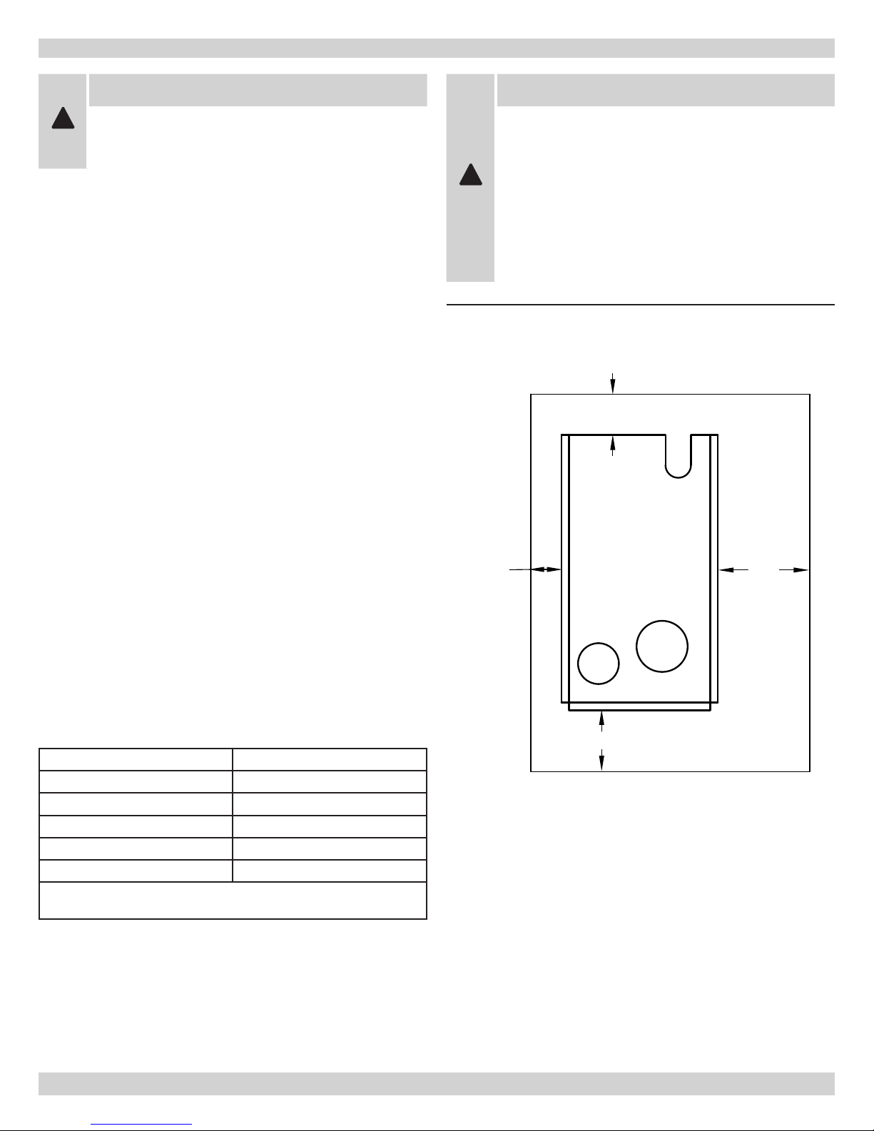
Figure 1 - Min. Clearances To Combustible Materials
WARNING
All installations of boilers and venting should
be done only by a qualied expert and in
accordance with the appropriate boiler
manual. Installing or venting a boiler or any
!
other gas appliance with improper methods or
materials may result in serious injury or death
due to re or to asphyxiation from poisonous
gases such as carbon monoxide which is
odorless and invisible.
4" (10.2 cm)
MIN.
• The boiler shall be installed such that the gas ignition
system components are protected from water, (dripping,
spraying, rain, etc.), during appliance operation and
service, (circulator replacement, condensate trap,
control replacement, etc.).
• For installation on non-combustible oors only.
The boiler must not be installed on carpeting (for
installation on combustible ooring special base
part no.325-2-8.00 Must be used). Minimum
clearances to combustible constructions are:
TOP 18 in. (46 cm)
FLUE CONNECTOR 2 in. (5 cm)
FRONT 6 in. (15 cm)
REAR 4 in. (10 cm)
RIGHT SIDE 9 in. (23 cm)
LEFT SIDE 3 in. (8 cm)
Refer to Figure 1. Greater clearances for access should supersede re protection clearances.
3"
(7.6 cm)
MIN.
6" (15.2 cm)
MIN.
9"
(22.9 cm)
MIN.
FRONT OF
BOILER
3
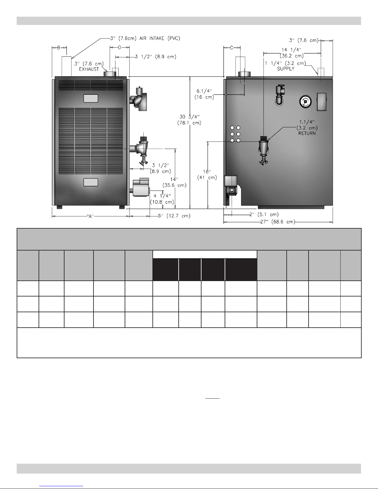
BOILER RATINGS, CAPACITIES & DIMENSIONS
Boiler Ratings, Capacities & Dimensions
Boiler
No.
3
Section
4
Section
5
Section
NOTE: Input rating for applications 0-2000 ft ( 0-610m) above sea level.
United States: Over 2000 ft (610m) above sea level. Reduce input rate 4% for every 1000 ft (304m) above sea level.
Canada: 2000-4500 ft (610-1350m) above sea level. Reduce input rate 10%.
Canada over 4500 ft (1350m) above sea level. Contact Provincial authority having jurisdiction.
Input
Btu/Hr.
50,000
(14.7 KW)
100,000
(29.3 KW)
140,000
(41.0 KW)
Heating
Capacity
Btu/Hr.
44,000
(12.9 KW)
87,000
(25.5 KW)
122,000
(35.7 KW)
Net Output
Btu/Hr.
38,000
(11.1 KW)
76,000
(22.3 KW)
107,000
(31.3 KW)
Natural
Gas
Inlet
1/2"
(1.27 cm)
1/2"
(1.27 cm)
1/2"
(1.27 cm)
A B C D
15.1/8"
(38 cm)
19"
(48 cm)
22.7/8"
(58 cm)
STANDARD EQUIPMENT:
Boiler Jacket, Cast Iron Boiler Battery, Limit Control, Removable Transformers, Plug in Relay, Theraltimeter Gauge,
Circulator (eld mounted), Main Gas Burners, Hot Surface
Pilot; A.S.M.E Relief Valve, Drain Valve, Induced Draft Fan,
Safety Pressure Switch, and Combination Intake/Exhaust
Termination Kit.
All boilers are design certied for installation on non-combustible oors. For installation on combustible oors, use
combustible oor kit.
Dimensions
3.1/2"
(9 cm)
3.1/2"
(9 cm)
4.1/4"
(11 cm)
3.1/2"
(9 cm)5"(12.7 cm)
3.1/2"
(9 cm)
4.1/8"
(11 cm)
6.1/2"
(16.5 cm)
8.3/8"
(21.3 cm)
This boiler is a Direct Vent Designed Certied appliance
which requires a special horizontal through the wall venting
system.
Use ONLY the venting material products listed below:
• HEAT-FAB® SAF-T-VENT
• FLEX-L® STAR-34™
• ProTech™ FasNSeal
• Z-FLEX® Z-VENT™
Consult venting addendum for maximum vent lengths and
proper congurations.
Supply &
Return
Tappings
1.1/4"
(3.2 cm)
1.1/4"
(3.2 cm)
1.1/4"
(3.2 cm)
®
™
No. Of
Burners
2
3
4
Water
Content
4.0 gals
(15.14 liters)
5.6 gals
(21.20 liters)
7.2 gals
(27.25 liters)
AFUE
Ratings
87%
87%
87%
Electrical service to be 120 Volts, 15 Amps, 60 Hz.
4
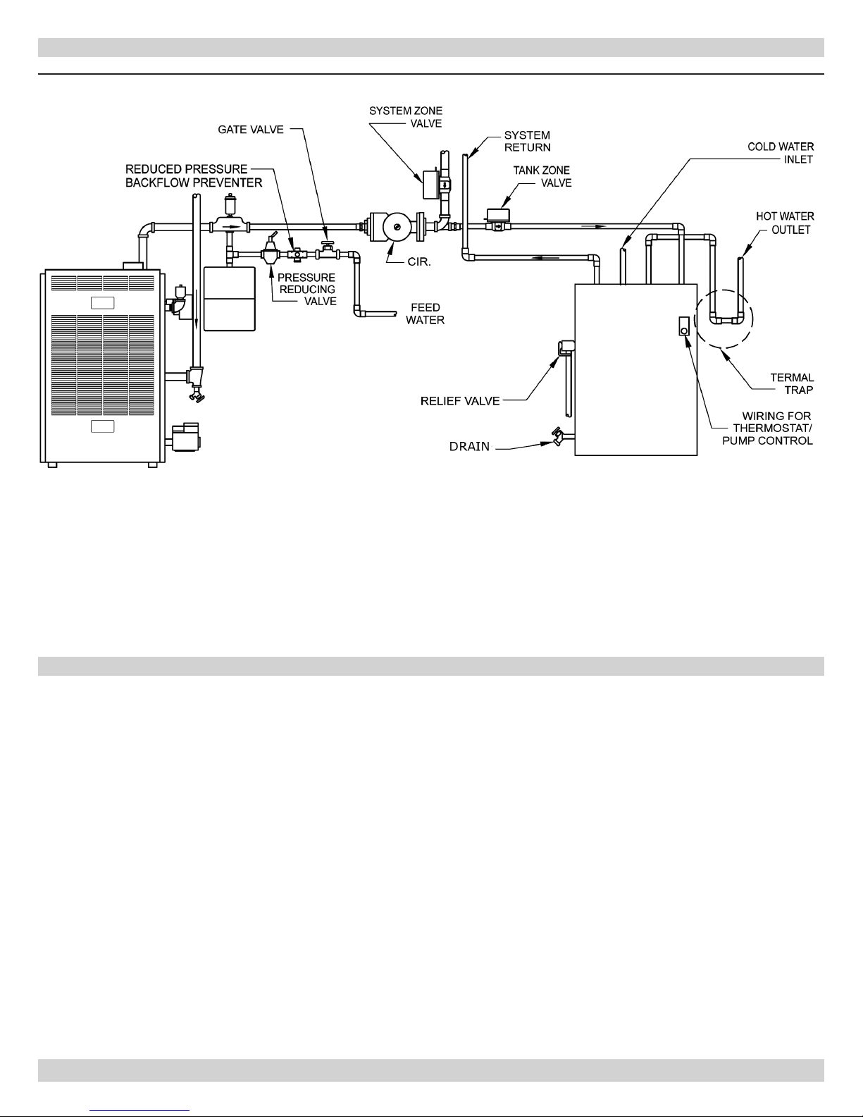
CONNECTING SUPPLY AND RETURN PIPING
1.
See Relief Valve Piping Supplemental Installation
Instructions located on page 40 of this manual.
2.
Connect supply and return piping as suggested in
Figure 1 below when the boiler is used in connection
with refrigerated systems:
A. Boiler used in connection with refrigeration
system. Install piping in parallel with boiler, with
appropriate valves to prevent chilled medium from
entering boiler. See gure 2.
B. System piping connected to heating coils located
in air handling unit exposed to refrigerated air
circulation. Install ow control valves or other
automatic means to prevent gravity circulation of
boiler water during cooling cycle.
3.
Maintain a minimum clearance of 1 inch (2.54cm) to
hot water pipes.
4.
Hot water boilers installed above radiation level or
as required by Authority having jurisdiction must be
provided with a low water cut-off device at the time of
boiler installation.
5.
When a boiler is connected to a heating system that
utilizes multiple zoned circulators, each circulator must
be supplied with a ow control valve to prevent gravity
circulation.
NOTICE
Reduced pressure back ow preventer must
be used under provisions required by the
Environmental Protection Agency, (EPA).
Figure 1 - Near Boiler Supply & Return Piping
A
EXPANSION
TANK
B
FEED
WATER
CHECK
VALV E
C
CHILLER
D
CIRCULATOR
SUPPLY PIPING
TO HEATING
AND COOLING
ELEMENT
WATER
RETURN PIPING
FROM HEATING
AND COOLING
ELEMENT
5
ZONE
CIR.
VALV E
FLOW
VALVE
EXPANSION
TANK
VALV E
SYSTEM
TEMPERATURE
GAUGE
RETURN
SUPPLY
"A"
"B"
WATER
FEED
ZONE
CIR.
EXPANSION
TANK
SYSTEM
TEMPERATURE
GAUGE
RETURN
SUPPLY
4 WAY MIXING
VALV E
WATER
FEED
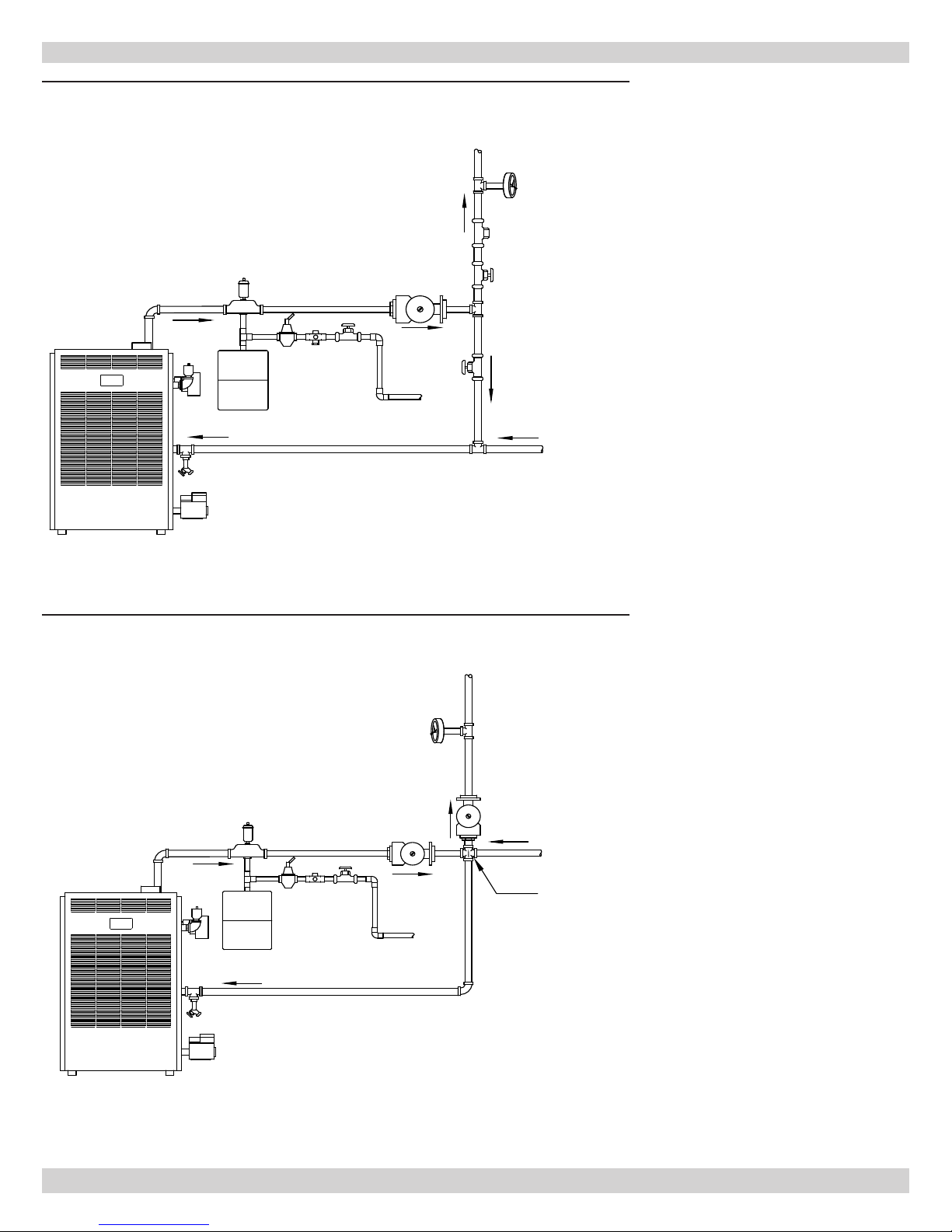
Figure 3 - Bypass Piping
CONNECTING SUPPLY AND RETURN PIPING
6.
Bypass piping is an option which
gives the ability to adjust the
supply boiler water temperature
to t the system or condition of
the installation. This method of
piping is not typically required for
baseboard heating systems.
A. This method is used
to protect boilers from
condensate forming due to
low temperature return water.
Generally noticed in large
converted gravity systems
or other large water volume
systems. See Figure 3.
B. These methods are used to
protect systems using radiant
panels and the material they
are encased in from high
temperature supply water
from the boiler and protect the
boiler from condensation. See
Figures 4 & 5.
Figure 3 - Mixing Valve Piping
7.
NOTE: When using bypass piping,
adjust valves A and B, in Figures
3 & 5, until desired system
temperature is obtained.
8.
NOTE: When using a 4-way
mixing valve, set control knob until
desired temperatures are met. See
instruction supplied with valve.
9.
Bypass loop piping must be the
same size piping as the supply and
the return.
10.
Typical installation using circulators
is shown in Figure 6 on following
page.
11.
Typical installation using zone
valves is shown in Figure 7 on
following page.
12.
For further piping information
refer to the I=B=R installation and
piping guide.
6

CONNECTING SUPPLY AND RETURN PIPING
Figure 5 - Primary Secondary Piping with Bypass
SYSTEM
TEMPERATURE
GAUGE
SUPPLY
FLOW
VALV E
PRIMARY
CIRCULATOR
"B"
VALV E
RETURN
SYSTEM
CIRCULATOR
12"
(31 cm)
MAX.
"A"
VALV E
EXPANSION
TANK
Figure 6 - Typical Installation Using Circulators
FEED
WATER
7
CONNECTING SUPPLY AND RETURN PIPING
Figure 7 - Typical Installation Using Zone Valves
GENERAL INFORMATION GAS VENTS AND APPLIANCES
By Federal Codes, gas appliances are categorized by the
pressure and temperature of the ue gas vented from the
appliance.
• Category I and II appliances are natural draft (draft
hood) vented, with high ue gas temperatures
(Category I), or low ue gas temperatures (Category
II).
• Category III and IV appliances are fan forced vents with
high temperature (Category III) or low temperature
(Category IV) ue gasses. Appliance efciency is directly
related to ue gas temperature. Higher efciency
appliances remove more heat from the gas, so they will
have lower temperature ue products.
• When ue gas temperatures are lowered, corrosive
condensates may form in the gas vent or in the
appliance. Condensates may form in Category II, III, IV
appliance vents, so special corrosive resistant venting
systems are required for higher efciency appliances.
8
• Proper operation of the vent system and appliance is
dependent upon the use of all parts specied by the
manufacturer for use in the particular installation.
Appliance and vent system performance may be affected
by improper assembly.
• Vents for Category I appliances may not be suitable
for use with Category II, III, or IV appliances because
condensate may corrode the vent.
• Vents for Category III appliances may not be suitable
for use with Category I appliances because ue gas
temperatures may be too high.

VENT PIPE MODIFICATION
When an existing boiler is removed from a common venting
system, the common venting system is likely to be too
large for the proper venting of the appliances remaining
connected to it.
REMOVAL OF BOILER FROM VENTING SYSTEM
At the time of removal of an existing boiler, the following
steps shall be followed with each appliance remaining
connected to the common venting system placed in
operation, while the other appliances remaining connected
to the common venting system are not in operation.
1.
Seal any unused openings in the common venting
system.
2.
Visually inspect the venting system for proper size and
horizontal pitch and determine there is no blockage or
restriction, leakage, corrosion and other deciencies
which could cause an unsafe condition.
3.
Insofar as is practical, close all building doors and
windows and all doors between the space in which the
appliances remaining connected to the common venting
system are located and other spaces of the building.
Turn on clothes dryers and any appliance not connected
to the common venting system. Turn on any exhaust
fans, such as range hoods and bathroom exhausts, so
they will operate at maximum speed. Do not operate a
summer exhaust fan. Close replace dampers.
4.
5.
6.
7.
Place in operation the appliance being inspected. Follow
the lighting instructions. Adjust thermostat so appliance
will operate continuously.
Test for spillage at the draft hood relief opening after
5 minutes of main burner operation. Use the ame of
a match or candle, or smoke from a cigarette, cigar or
pipe.
After it has been determined that each appliance
remaining connected to a common venting system
properly vents when tested as outlined above, return
doors, windows, exhaust fans, replace dampers and
any other gas burning appliance to their previous
conditions of use.
Any improper operation of the common venting system
should be corrected so the installation conforms with
the National Fuel Gas Code, ANSI Z223.1/NFPA 54,
and/or the Natural Gas and Propane Installation Code,
CAN/CSA B149.1. When re-sizing any portion of the
common venting system, the common venting system
should be re-sized to approach the minimum size as
determined using the appropriate tables in Chapter 13
of the National Fuel Gas Code, ANSI Z223.1/NFPA 54,
and/or the Natural Gas and Propane Installation Code,
CAN/CSA B149.1.
9

CONNECT GAS SERVICE
CAUTION
WHAT TO DO IF YOU SMELL GAS
Do not try to light any appliance.
Do not touch any electrical switches; do
not use any phones in your building.
!
Immediately call your gas supplier from
a neighbor’s phone. Follow gas supplier’s
instructions.
If you cannot reach your gas supplier, call
the re department.
The following rules apply:
1.
Use piping materials and joining methods acceptable
to authority having jurisdiction. In absence of such
requirements:
USA - National Fuel Gas Code, ANSI Z223.1/NFPA 54
Canada - Natural Gas and Propane Installation Code,
CAN/CSA B149.1
2.
All pipe compound must be resistant to liqueed
petroleum gas.
3.
Install ground joint union in gas supply line between
shut-off valve and boiler controls.
4.
Install a sediment trap upstream of gas controls.
5.
Use two pipe wrenches when making the connection to
the gas valve to keep it from turning.
6.
Install manual shut-off valve in vertical pipe about 5
feet (1.5m) above oor.
7.
Tighten all joints securely.
8.
Propane gas connections should only be made by a
licensed propane installer.
9.
Two-stage regulation should be used by the propane
installer.
10.
Propane gas piping should be checked out by the
propane installer.
DANGER
Fire Hazard. Do not use matches, candles,
!
open ames, or other methods providing
ignition source. Failure to comply will result in
death or serious injury.
Checking The Gas Piping
Pressure test boiler and gas connection before placing
boiler in operation.
• Pressure test over 1/2 psig (3.5 kPa). Disconnect
boiler and its individual gas shutoff valve from gas
supply system.
• Pressure test at 1/2 psig (3.5 kPa) or less. Isolate
boiler from gas supply system by closing manual gas
shutoff valve. See Figure 8.
• Locate leakage using gas detector, noncorrosive
detection uid, or other leak detection method
acceptable to authority having jurisdiction. Do not
use matches, candles, open ames, or other methods
providing ignition source.
• Correct leaks immediately and retest.
Figure 8 - Manual Gas Shutoff Valve
10
ELECTRICAL WIRING
The boiler, when installed, must be electrically bonded
to ground in accordance with the requirements of the
authority having jurisdiction or, in the absence of such
requirements, with the National Electrical code, ANSI/NFPA
70, and/or the Canadian Electrical Code Part I, CSA C22.1,
Electrical Code.
WARNING
Electrical shock hazard. Turn OFF electrical
!
power supply at service panel before making
electrical connections. Failure to do so could
result in death or serious injury.
Component And Wire Coding Keys
• The keys that follow pertain to the HOT WATER
CONTROL AND HOT SURFACE PILOT WIRING FOR
SEALED COMBUSTION SERIES (diagrams on following
page).
• If any of the original wiring supplied with the boiler is
replaced it must be replaced with like wire size and type
of insulation or equivalent.
COMPONENT KEY CODING
Thermostat (24 Volt)
Transformer (120V/24V 40VA)
Transformer (120V/24V 40VA)
24 Volt Gas Valve
Pressure Switch
Control Terminal
Relay Coil
Relay Contacts
Relay Contacts
Limit Switch
Circulator
Wire Connection
TH-2
TR-1
TR-2
SV9501H
PS
1K
1K1
1K2
LS
CIR
Not all components listed are used in all control
systems.
WIRING CODE KEY
CAUTION
Label all wires prior to disconnection when
!
servicing controls. Wiring errors can cause
improper and dangerous operation. Verify
proper operation after servicing.
Install Your Thermostat
• The thermostat location has an important effect on the
operation of your boiler system.
• BE SURE TO FOLLOW THE INSTRUCTIONS INCLUDED
WITH YOUR THERMOSTAT.
• Locate the thermostat about four feet (4’) above the
oor on an inside wall.
• Check thermostat operation by raising and lowering
thermostat setting as required to start and stop burners.
LINE VOLTAGE BY FACTORY
LOW VOLTAGE BY FACTORY
LINE VOLTAGE BY INSTALLER
LOW VOLTAGE BY INSTALLER
THINGS TO AVOID WHEN
LOCATING THERMOSTATS
DEAD SPOTS:
Corners and alcoves Behind doors
COLD SPOTS: HOT SPOTS:
Concealed pipes or ducts
Stairwells - drafts
Unheated rooms on
other side of wall
Outside wall
Concealed pipes
Fireplace or chimney
TV sets
Radios
Lamps
Direct sunlight
Kitchens
11
ELECTRICAL WIRING
HOT WATER CONTROL AND HOT SURFACE PILOT WIRING
SV9501H
GREEN
AND
WHITE
CONTROL
Honeywell
Q3450B
IGNITION
RED
ORANGE
GREEN
120V
60HZ
SUPPLY
INDUCED
LM
DRAFT
BLOWER
LS
L4080B
BLUE
FT
TV
T
BLUE
NO
CIR
L1
L2
C2
C
PS
VM
B
C1
ORANGE
VM/LM
3 6
1K
TH-2
1 4
TR-2TR-1
R8222C
GREEN
AND
WHITE
CONTROL
Honeywell
Q3450B
SV9501H
IGNITION
GREEN
RED
ORG
120V
60HZ
SUPPLY
PS
NO
ORG
WHITE
C
BLACK
YELLOW
CIR
L1
WHITE
LS
L4080B
INDUCED
DRAFT
BLOWER
BLUE
VM
RED
FT
LM
3 6
1K1
1 4
L2
C2
VM
LM
C1
BLACK
RED
YELLOW
B
T
TV
BLUE
1K
BLUE
TH-2
ORG
1K2
BLUE
12

OPERATING INSTRUCTIONS
FOR BOILER WITH A HOT SURFACE PILOT SYSTEM
FOR YOUR SAFETY, READ BEFORE OPERATING!
WARNING
If you do not follow these instructions exactly,
!
a re or explosion may result causing property
damage, personal injury or loss of life.
Before operating, make certain the boiler and system are
full of water to minimum pressure (this is usually 12 psig
on most systems) and system is vented of air. See the
operating and lighting instructions.
WARNING
A. This appliance is equipped with an ignition
device which automatically lights the
burner. Do not attempt to light the burner
by hand.
B. BEFORE OPERATING smell all around the
appliance area for gas. Be sure to smell
next to the oor because some gas is
heavier than air and will settle on the
oor.
WHAT TO DO IF YOU SMELL GAS
• Do not try to light any appliance.
• Do not touch any electrical switch; do not
use any phone in your building.
!
• Immediately call your gas supplier from
a neighbor’s phone. Follow gas supplier’s
instructions.
• If you cannot reach your gas supplier, call
the re department.
C. Use only your hand to push down or turn
the knob. Never use tools. If the knob will
not operate by hand, don’t try to repair it,
call a qualied service technician. Force
or attempted repair may result in re or
explosion.
D. Do not use this appliance if any part
has been underwater. Immediately call
a qualied service technician to inspect
the appliance and to replace any part of
control system and any gas control which
has been under water.
13
ON
OFF
GAS
GAS
PRESSURE REGULATOR
ADJUSTMENT BENEATH
COVER SCREW
PILOT FLOW ADJ.
SCREW BENEATH
CONTROL
IGNITER
IGNITION SYSTEM
COVER SCREW
CONTROL SWITCH
PRESSURE
TAP
OUTLET
INLET
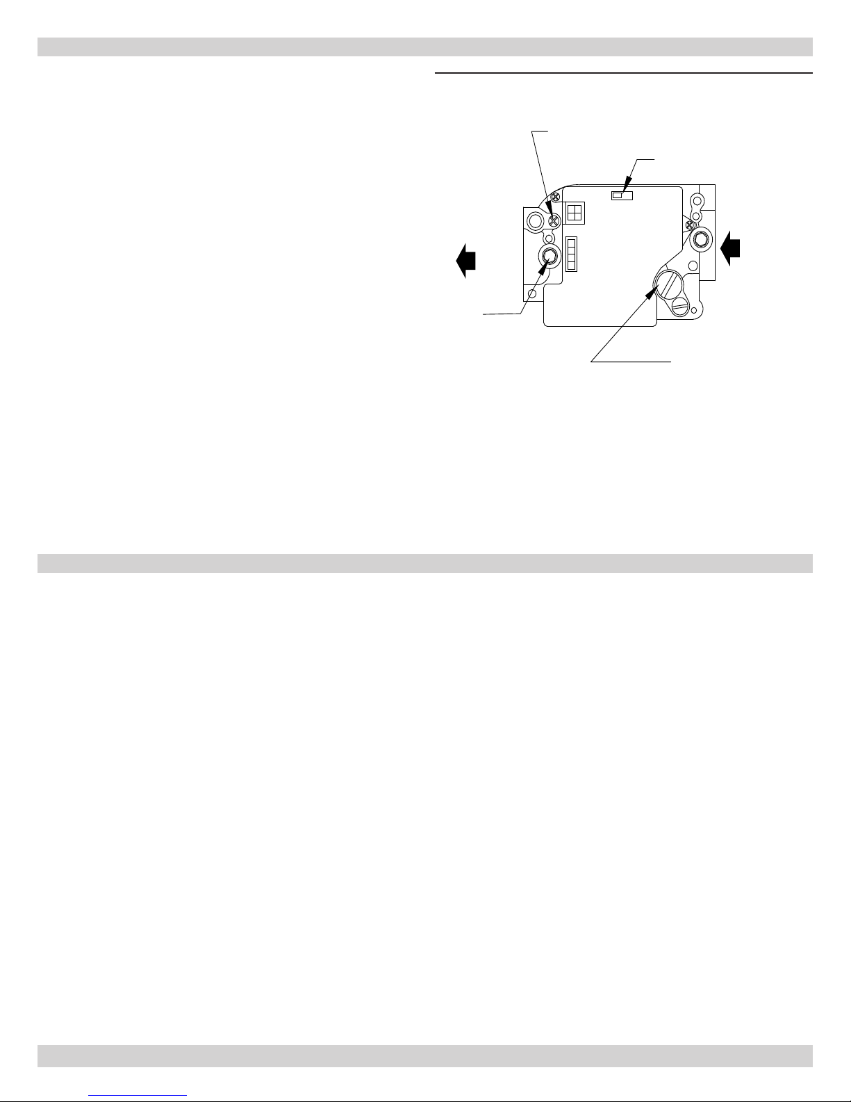
OPERATING INSTRUCTIONS
OPERATING INSTRUCTIONS
1.
STOP! Read the safety information on previous page.
2.
Set thermostat to lowest setting.
3.
Turn off all electric power to the appliance.
4.
This appliance is equipped with an ignition device which
automatically lights the pilot. DO NOT try to light the
pilot by hand.
5.
Move the ignition system control switch to the "OFF"
position. See Figure 10.
6.
Wait ve (5) minutes to clear out any gas. If you then
smell gas, STOP. Follow "What To Do If You Smell Gas"
on previous page. If you don't smell gas, go to next
step.
7.
Move the ignition system control switch to the "ON"
position. See Figure 10.
8.
Turn on all electric power to the appliance.
9.
Set thermostat to desired setting.
10.
If the appliance will not operate, follow the instructions
"To Turn Off Gas To Appliance" to right and call a
qualied service technician or your gas supplier.
Figure 10 - Gas Control Screw
TO TURN OFF GAS TO APPLIANCE
1.
Set thermostat to lowest setting.
2.
Turn o all electric power to the appliance if service is to
be performed.
3.
Move the ignition system control switch to the "OFF"
position. DO NOT FORCE
SEQUENCE OF OPERATION
On a call for heat:
1.
The thermostat will actuate, completing the circuit
between terminals T and T.
2.
The R8222C relay coil will energize thus pulling in the
relay contacts.
3.
The circulator starts and power is switched to the limit.
If limit circuit is closed the venter motor and TR-2
transformer are energized.
4.
The venter motor starts and develops static pressure.
5.
When the static pressure is reached the pressure switch
pulls in completing the circuit between TR-2 and the
SV9501H gas valve system.
6.
7.
The SV9501H opens the pilot valve and ignites pilot.
After pilot is proven the main burner will ignite.
In the event the boiler water temperature exceeds the
high limit setting the power will be interrupted to the
venter motor, and TR-2, thus interrupting power to the
ignition system. Power will remain off until the water
temperature drops below the high limit setting. The
circulator will continue to operate under this condition
until the thermostat is satised.
8.
Should the air ow (static pressure) be interrupted (ie.
blocked ue), the pressure switch will sense a drop
in pressure, opening the circuit between the ignition
system and TR-2. The venter motor will continue to
operate until static pressure is reached or thermostat is
satised.
9.
In the event the ow of combustion products through
the boiler ue-ways becomes reduced or blocked, the
Q34505 pilot will lose ame rectication and shut off
the main burners. The boiler will try for ignition but
will not light. If this condition occurs, turn off the main
power and do not put the unit into operation.
10.
When the thermostat is satised power is interrupted to
the relay coil and the relay drops out cutting power to
the circulator, venter motor, and TR-2.
14
 Loading...