

Columbia CEGDID112D, CEGDID262D, CEGDID187D, CEGDID225D, CEGDID299D Installation, Operation & Maintenance Manual
...
C
OLUMBIA
Main offi ces and Factory:
Pottstown, PA
C
OMPANY
Models
CEGDID075D
CEGDID11 2 D
CEGDID150 D
CEGDID18 7D
CEGDID225D
CEGDID262 D
CEGDID299D
GAS-FIRED STEAM BOILERS
INST ALLATI ON, OPERATI ON &
MAINTENANCE MANUAL
MODEL
CEGDID
Electronic
Intermittent
Ignition
Manufacturedby:
ECRInternational,Inc.
2201 Dwyer Avenue, Utica NY 13504-4729
web site: www.ecrinternational.com
P/N# 240009573, Rev. D [08/2012]

Figure 1 - Dimensions
DIMENSIONS
16⅝"
12⅜"
2" NPT
25"
13½"
2" NPT
½" NPT
Plug
5½"
Floor
A
Depth C
Safety
Relief
Valve
2" NPT
B
29"
2" NPT
Models 075 112 150 187 225 262 299
Width (A)
Height (B)
Depth (C)
Gas
Connection Size (G)
Flue Diameter
Table 1 - Physical Data
10 7/
28 3/
½ NPT ½ NPT ½ NPT ¾ NPT ¾ NPT ¾ NPT ¾ NPT
5" 5" 6" 7" 7" 7" 7"
14 1/
8
28 3/
8
17 3/
8
29 3/
8
20 5/
8
35 7/
30 3/
8
23 7/
8
8
30 3/
8
27 1/
8
30 3/
8
30 3/
8
8
30 3/
8
8
2
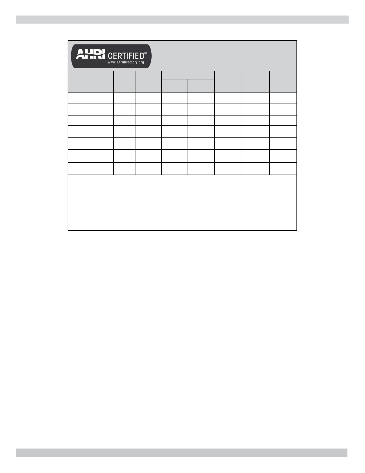
BOILER RATINGS AND CAPACITIES
Table 2
Ratings and Capacities
Natural Gas & Propane (LP)
Boiler Model
Number
Input
MBH (1)
Heating
Capacity
MBH (1)
CEG075DID 75 62 47 195 82.2 3 5"
CEG112DID 112 93 70 292 82.4 4 6"
CEG150DID 150 125 94 391 82.6 5 6"
CEG187DID 187 156 117 488 82.8 6 7"
CEG225DID 225 188 141 587 83.0 7 7"
CEG262DID 262 219 164 685 83.2 8 7"
CEG299DID 299 250 188 782 83.4 9 7"
Heating Capacity and AFUE are based on DOE (Department of Energy) test procedures.
1. Input rating for sea level to 2,000 ft. above sea level.
level, reduce input rate 4% for every 1000 ft.
2. Net AHRI steam ratings shown are based on a piping and pickup allowance of 1.333.
Consult manufacturer before selecting a boiler for installations having unusual piping
and pickup requirements, such as intermittent system operation, extensive piping
systems, etc.
Net AHRI Rating (2)
Steam,
MBH
Steam,
Sq. Ft.
AFUE, %
Altitudes over 2000 ft. above sea
No. of
Sections
Vent Pipe
Size
3

TABLE OF CONTENTS
Important Safety Information ....................... 5
Locating the Boiler ...................................... 6
Hydronic Piping .......................................... 7
Fresh Air for Combustion ............................11
Chimney and Vent Pipe Connection ..............12
Vent Damper Operation ..............................14
Gas Supply Piping ......................................15
Electrical Wiring ........................................16
Operating Instructions ................................17
Operating Your Boiler .................................18
Checking and Adjusting ..............................19
Start-up Cleaning ......................................21
General Maintenance .................................22
Troubleshooting .........................................23
Wire Diagrams ..........................................24
Optional Hydronic Piping .............................27
Introduction
Boiler is designed for use in closed heating systems where
all steam is returned as condensate and make-up water is
minimal. Boiler is not designed for or intended for use in
open systems using 100% make-up water.
Prior to Installation
• Verify correct boiler for type of gas being used
natural or propane. See Rating Plate.
• Verify boiler size and dimensions. See Figure 1 and
Table 1, page 2.
• Verify ratings and capacity data for natural gas. See
Table 2.
Installation Requirements
• Supply boiler with correct gas (natural or propane),
fresh air for combustion, and suitable electrical supply.
• Connect boiler to adequate venting and piping
systems.
• Provide boiler with properly located and adjusted
thermostat.
Installation of boiler in building under construction, use
precaution to insure clean combustion air supply during
construction process. Airborne particulate from construction
materials can clog burner ports and cause incomplete
combustion and sooting.
Complete all steps for safe and proper heating system
operation.
KEEP THIS MANUAL NEAR BOILER
RETAIN FOR FUTURE REFERENCE
GAS FIRED STEAM BOILERS
Check our website frequently for updates: www.ecrinternational.com
Information and specifi cations outlined in this manual in effect at the
time of printing of this manual. ECR International reserves the right to
discontinue, change specifi cations or system design at any time without
notice and without incurring any obligation, whatsoever.
4
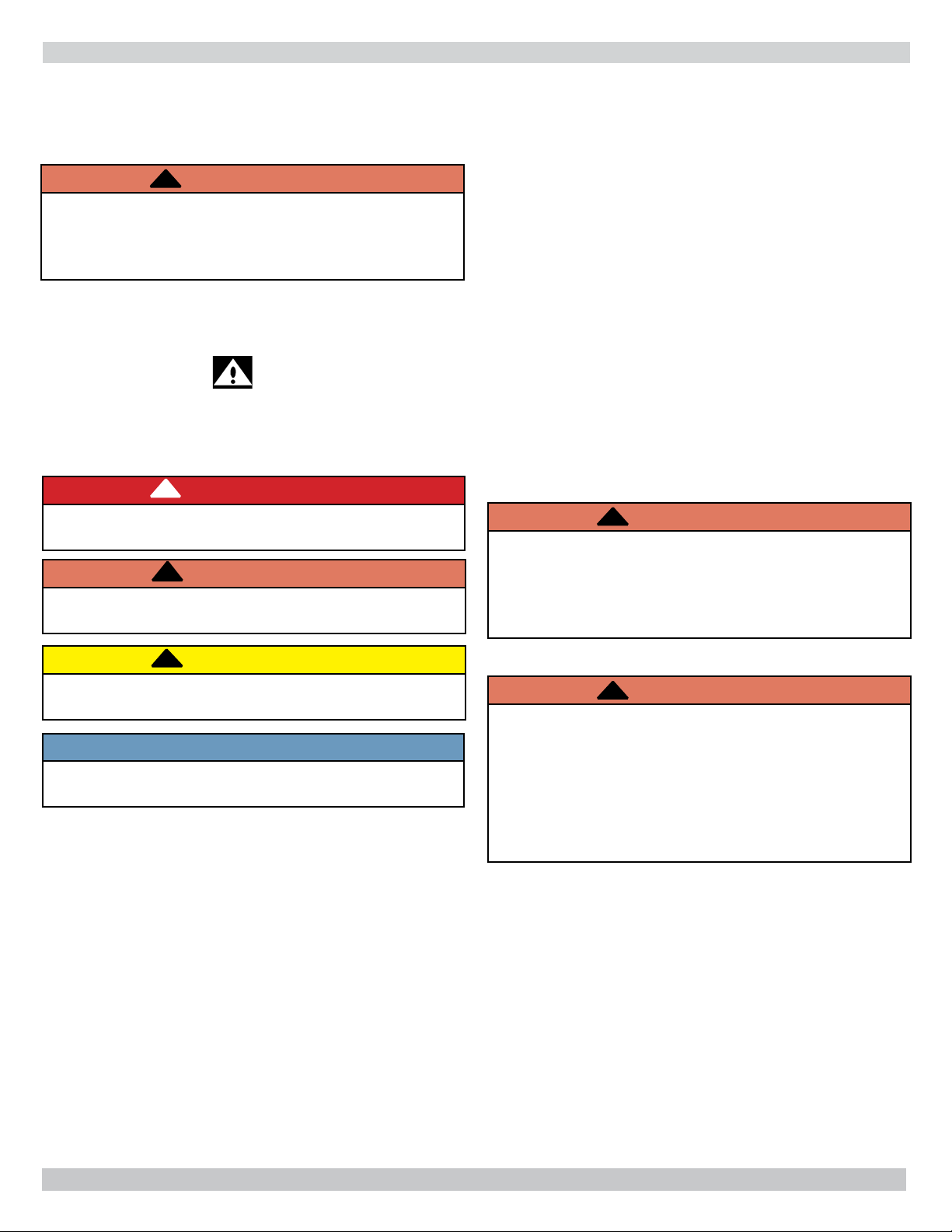
IMPORTANT SAFETY INFORMATION
!
Become familiar with symbols identifying potential
hazards.
This is the safety alert symbol. Symbol alerts you to
potential personal injury hazards. Obey all safety messages
following this symbol to avoid possible injury or death.
General
Boiler and venting installation shall be completed by
qualifi ed agency.
WARNING
!
Fire, explosion, asphyxiation and electrical shock
hazard. Improper installation could result in death
or serious injury. Read this manual and understand
all requirements before beginning installation.
Become familiar with symbols identifying potential
hazards.
This is the safety alert symbol. Symbol alerts you to
potential personal injury hazards. Obey all safety messages
following this symbol to avoid possible injury or death.
!
DANGER
Indicates a hazardous situation which, if not avoided,
WILL result in death or serious injury.
!
WARNING
Indicates a hazardous situation which, if not avoided,
could result in death or serious injury.
Installation shall conform to requirements of
authority having jurisdiction or in absence of such
requirements
ANSI Z223.1/NFPA 54.
Where required by authority having
jurisdiction, installation shall conform to
Standard for Controls and Safety Devices for
Automatically Fired Boilers, ANSI/ASME CSD-1.
Controls can be added to make this boiler CSD1 compliant. Check with your local codes for
requirements.
Requirements for Commonwealth of Massachusetts:
Boiler installation must conform to Commonwealth of
Massachusetts code 248 CMR which includes but is
not limited to installation by licensed plumber or gas
fi tter.
Installing or venting a boiler or any other gas
appliance with improper methods or materials could
result in death or serious injury due to fi re or to
asphyxiation from poisonous gases such as carbon
monoxide which is odorless and invisible.
to the National Fuel Gas Code,
WARNING
!
!
CAUTION
Indicates a hazardous situation which, if not avoided,
may result in minor or moderate injury.
NOTICE
Used to address practices not related to personal
injury.
WARNING
!
Fire, explosion, asphyxiation hazard. Keep boiler area
clear and free from combustible materials, gasoline
and other fl ammable vapors and liquids.
Modifi cation, substitution or elimination of factory
equipped, supplied or specifi ed components could
result in death or serious injury.
5
LOCATING THE BOILER
Locating the Boiler
1.
Select level location as centralized with piping system,
and as near chimney as possible.
2.
Place crated boiler at selected location. Remove all
crate material. Please recycle responsibly.
!
WARNING
Fire hazard. Do not install boiler on combustible
fl ooring or carpeting. Failure to follow these
instructions could result in death or serious injury.
3.
Do not install boiler on carpeting. For installation
on non-combustible fl oors only. For installation on
combustible fl ooring, special base must be used. (See
Replacement Parts Manual.)
4.
Use metal shims under boiler base legs for fi nal leveling
if needed.
5.
Install boiler in location that permits satisfactory
combustion of gas, proper venting, and maintenance
of ambient temperature at safe limits under normal
conditions of use. Boiler location should not interfere
with proper circulation of air. Introduce outside air
if normal infi ltration does not provide necessary
air. “Fresh Air for Combustion” on page 11 .
6.
Notify owner to keep air passages free of obstruction.
Ventilating and combustion air must enter boiler room
without restrictions.
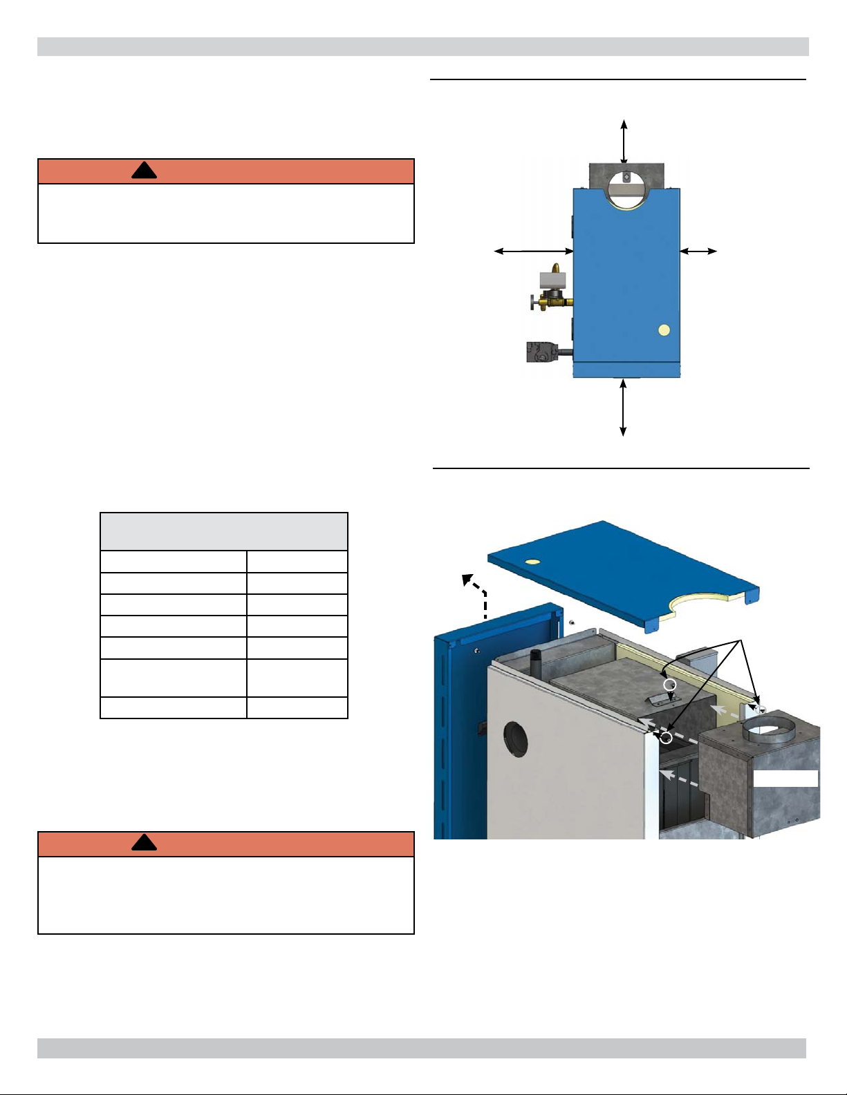
Table 3 -
Minimum Clearance Dimensions
Top 6"
Rear 6"
Control Side 7"
Opposite Side 6"
Front Alcove
Flue/Vent
Connector
Near Boiler Piping 1/2"
6"
Figure 2 - Minimum Clearances To Combustible
Construction
7”
Figure 3 - Draft Hood Installation
Front Panel
Lift Up
Then Off
6”
Rear
Boiler
Control Side
Front
ALCOVE
6”
Opposite Side
Screws
7.
Install boiler so automatic gas ignition system
components are protected from water (dripping,
spraying, rain, etc.) during appliance operation and
service.
Draft Hood Installation
!
WARNING
Asphyxiation, carbon monoxide hazard. Failure to
follow these instructions could result in improper
combustion and possible leakage of combustion
products into the living space.
Follow directions given in Figure 3. Attach draft diverter,
and blocked vent switch. Mount vent damper. See
"Connecting Vent Damper and Vent Connector" page 12.
See Wiring Diagrams pages 24 and 25.
1.
Lift up then off to remove front panel.
2.
Remove top jacket panel (4 screws).
3.
Slide draft hood over fl ue collector.
4.
Secure with 1 or 2 screws, based on boiler size.
5.
Replace top jacket panel (4 screws).
6.
Replace front panel.
6
Draft Hood
HYDRONIC PIPING
!
WARNING
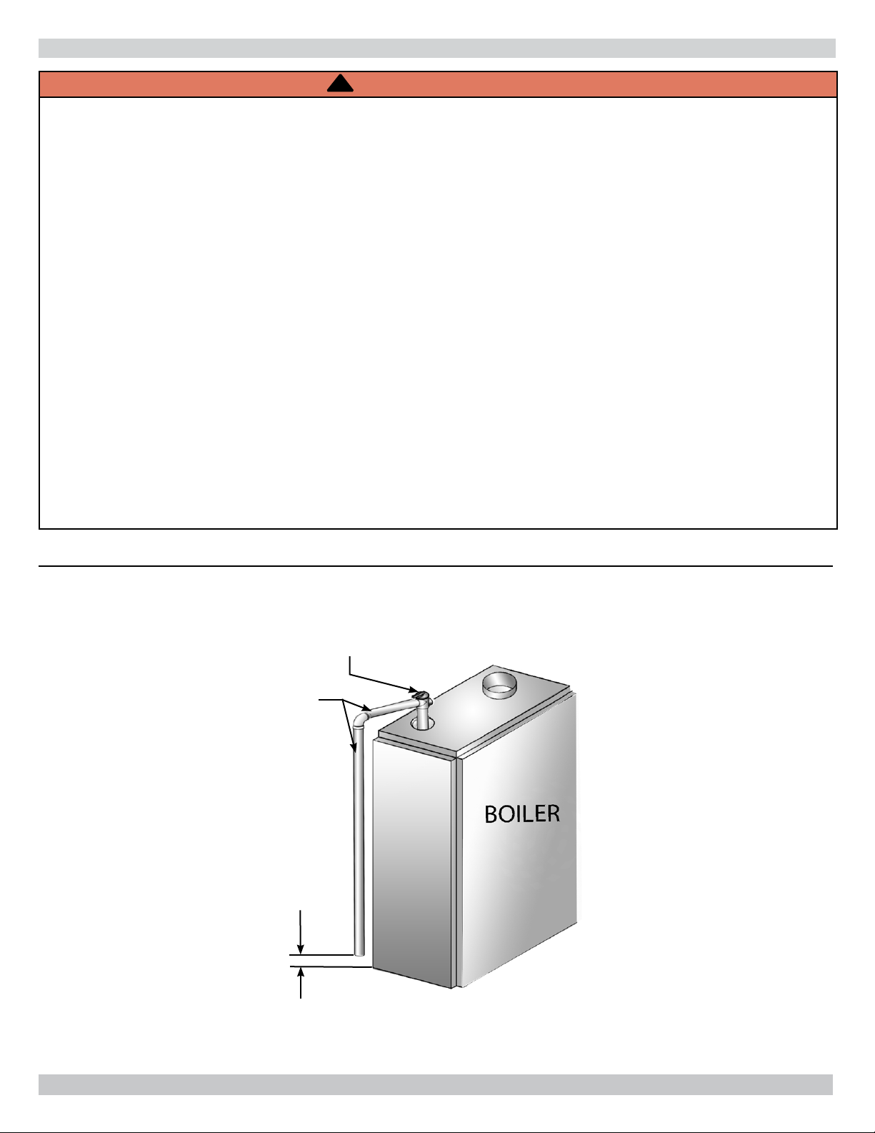
Burn or Scald Hazard. Discharge line shall be installed to relief valve outlet connection to avoid burns,
scalding, or water damage due to discharge of steam and/or hot water during operation.
Discharge line shall:
• Connect to safety valve outlet. Piped down to safe point of disposal. Check local codes for maximum
distance from fl oor or allowable safe point of discharge.
• Pipe size be of equal to or greater than of safety valve outlet over entire length of discharge line.
• Have no intervening shutoff valve between safety valve and discharge to atmosphere. Do not plug or
place any obstruction in discharge line.
• Terminate freely to atmosphere where any discharge will be clearly visible and at no risk of freezing.
• Allow complete drainage of valve and discharge line.
• Install safety valve with spindle in vertical position.
• Do not install shutoff valve between boiler and safety valve.
• Support safety valve discharge piping.
• Be short and straight as possible.
• Terminate with plain end, not threaded.
• Constructed of material suitable for exposure to temperatures of 375° F (191°C); or greater.
Refer to local codes and appropriate ASME Boiler and Pressure Vessel Code for additional installation
requirements.
Figure 4 - Safety Valve
Safety Valve
Discharge
Piping
Check local codes
for maximum
distance from
fl oor or other
allowable safe
point of discharge
6" Above Floor
7
HYDRONIC PIPING
Consider near boiler piping as part of the boiler for proper
water level control and to produce dry steam.
Correct near boiler piping is crucial to proper operation of
boiler and heating system.
Follow these recommendations carefully.
1.
Place boiler in selected location as near chimney as
possible.
2.
Install safety valve. Figure 4 and Warning on Page 7.
• Install union, if used, close to safety valve outlet.
• Install elbows close to safety valve outlet and
downstream of union (if used).
3.
Boiler is equipped with two 2" supply connections and
two 2" return connections, one each on both left and
right sides of boiler. Plug unused connections with
furnished 2" plug and 2 x ¾ " bushing for drain valve.
4.
When using both supply tappings to pipe system.
Figure 5b , Page 9
• Fit headers with header offsets, swing joints, or equip
with expansion joints, so thermal expansion and
contraction of header does not damage boiler. Do not
weld headers.
• Place system takeoffs from header between equalizer
and riser to header nearest equalizer. System takeoffs
must never be between two risers. If steam main goes
in two directions, place two takeoffs from header, one
for each main.
5.
Recommended near boiler piping for gravity return
systems is shown in Figure 7 page 10. For gravity return
systems, bottom of lowest steam carrying pipe, dry
return or end of steam main, must be at least 28” above
normal water level line on left side of boiler.
6.
Equip all boilers in gravity return systems with Hartford
Loop as shown in Figure 5a and 5b page 9.
7.
Piping vertical risers from boiler to header, risers must
be minimum of 24" high above water line..
8.
Steam riser(s) and header shall be 2" pipe size.
9.
Equalizer line shall be minimum 1-1/2" pipe size.
10.
Near boiler piping shall include 2" tee with female
adapter and cap located on supply line as shown for
skimming (i.e. surface blow-down).
11.
For pumped return systems, follow condensate pump
or boiler feed pump manufacturer’s instructions for
proper installation and hookup. See Table 3 and Figure
6 page 10.
12.
Connecting cold water supply to water inlet valve,
verify clean water supply is available. When water
supply is from well or pump, install sand strainer at
pump.
Table 3 - Steam Flow Rates (Gross)
Sections Flow Rates LBS/HR
3
4 94.7 LBS/HR
5 126.8 LBS/HR
6 158.1 LBS/HR
7 190.2 LBS/HR
8 221.5 LBS/HR
9 252.8 LBS/HR
63.4 LBS/HR
8

HYDRONIC PIPING
Figure 5a - Recommended Near Boiler Piping Using One Supply Tapping
Main Vent
Sections Risers Headers Equalizers
32"2" 1½
Header
28"
24"
42"2" 1½
Cap To
Skimmer Tee
2"
Close Nipple
24"
Equalizer 1½"
For Alternate Piping
Confi gurations See Page 27
Floor
Figure 5b - Recommended Near Boiler Piping Using Two Supply Tappings
Sections Risers Headers Equalizers
5 (2) 2" 2" 1½
Main Vent
Header
6 (2) 2" 2" 1½
7 (2) 2" 2½" 1½
8 (2) 2" 3 1½
9 (2) 2" 3 1½
Water Line
28"
24"
Close Nipple
Equalizer 1½"
For Alternate Piping
Confi gurations See Page 27
2"
Cap To
Skimmer Tee
Water Line
24"
Floor
9
 Loading...