

Columbia CEG-C, CEG112C, CEG150C, CEG187C, CEG225C Installation Manual And Operating Instructions
...
CEG-CCEG-C
CEG-C
CEG-CCEG-C
GAS FIRED BOILERS
FOR STEAM HEATING
UCTIONSUCTIONS
UCTIONSUCTIONS
UCTIONS
TING INSTRTING INSTR
TING INSTRTING INSTR
TING INSTR
Columbia Boiler Company
Main Offices and Factory: Pottstown, PA
AND OPERAAND OPERA
AND OPERAAND OPERA
AND OPERA
AL AL
AL AL
AL
TION MANUTION MANU
TION MANUTION MANU
TION MANU
ALLAALLA
ALLAALLA
ALLA
INSTINST
INSTINST
INST

TT
ABLE OF CONTENTSABLE OF CONTENTS
T
ABLE OF CONTENTS
TT
ABLE OF CONTENTSABLE OF CONTENTS
Safety Symbols & Warnings ................................................................................. Page 1
Installation Procedure ........................................................................................... Page 2
Ventilation and Combustion Air ...................................................................... Pages 3-4
Connecting Supply and Return Piping ............................................................... Page 5-6
Vent Installation .................................................................................................... Page 7
Vent System Modification ..................................................................................... Page 8
Vent Damper Installation and Instructions ........................................................... Page 9
Connecting Gas Service ..................................................................................... Page 10
Electrical Wiring .................................................................................................. Page 10
Thermostat Installation ....................................................................................... Page 11
Lighting Instructions ................................................................................... Pages 11-13
Normal Sequence of Operation .......................................................................... Page 14
Connecting Supply And Return Piping Water-Chilled Medium ........................... Page 15
General Instructions .................................................................................... Pages 16-20
Replacement Parts Lists ............................................................................. Pages 20-25
Ratings, Data and Dimensions .......................................................................... Page 26
KEEP THIS MANUAL NEAR BOILER
RETAIN FOR FUTURE REFERENCE
SERIES CEG-C
CAST IRON
GAS FIRED BOILERS
INSTALLATION MANUAL AND
OPERATING INSTRUCTIONS
Published April 1997
Printed in USA
Made in USA
A.G.A. Certified
for Natural gas
or Propane
Tested for 100 lbs.
ASME Working
Pressure
Safety SymbolsSafety Symbols
Safety Symbols
Safety SymbolsSafety Symbols
The following defined symbols are used throughout this manual to notify the
reader of potential hazards of varying risk levels.
DANGERDANGER
DANGER
DANGERDANGER
DANGER - Indicates an imminently hazardous situation which, if not avoided, WILL
result in death or serious injury.
WW
ARNINGARNING
W
ARNING
WW
ARNINGARNING
WARNING - Indicates a potentially hazardous situation which, if not avoided, COULD
result in death or serious injury
CAUTIONCAUTION
CAUTION
CAUTIONCAUTION
CAUTION - Indicates a potential hazardous situation which, if not avoided, MAY result
in minor or moderate injury. It may also be used to alert against unsafe practices.
IMPORIMPOR
IMPOR
IMPORIMPOR
1. Keep boiler area clear and free from combustible materials, gasoline and other
flammable vapors and liquids.
2. DO NOT obstruct air openings to the boiler room.
3. Modification, substitution or elimination of factory equipped, supplied or specified
components may result in property damage, personal injury or the loss of life.
4. To the owner: Installation and service of this boiler must be performed by a qualified
installer.
5. To the installer: Leave all instructions with the boiler for future reference.
SHOULD BE DONE ONLY BY A QUALIFIED EXPERT AND INSHOULD BE DONE ONLY BY A QUALIFIED EXPERT AND IN
SHOULD BE DONE ONLY BY A QUALIFIED EXPERT AND IN
SHOULD BE DONE ONLY BY A QUALIFIED EXPERT AND INSHOULD BE DONE ONLY BY A QUALIFIED EXPERT AND IN
ACCORDANCE WITH THE APPROPRIATE COLUMBIA BOILERSACCORDANCE WITH THE APPROPRIATE COLUMBIA BOILERS
ACCORDANCE WITH THE APPROPRIATE COLUMBIA BOILERS
ACCORDANCE WITH THE APPROPRIATE COLUMBIA BOILERSACCORDANCE WITH THE APPROPRIATE COLUMBIA BOILERS
MANUAL. INSTALLING OR VENTING A BOILER OR ANY OTHER GASMANUAL. INSTALLING OR VENTING A BOILER OR ANY OTHER GAS
MANUAL. INSTALLING OR VENTING A BOILER OR ANY OTHER GAS
MANUAL. INSTALLING OR VENTING A BOILER OR ANY OTHER GASMANUAL. INSTALLING OR VENTING A BOILER OR ANY OTHER GAS
APPLIANCE WITH IMPROPER METHODS OR MATERIALS MAY RESULTAPPLIANCE WITH IMPROPER METHODS OR MATERIALS MAY RESULT
APPLIANCE WITH IMPROPER METHODS OR MATERIALS MAY RESULT
APPLIANCE WITH IMPROPER METHODS OR MATERIALS MAY RESULTAPPLIANCE WITH IMPROPER METHODS OR MATERIALS MAY RESULT
IN SERIOUS INJURY OR DEATH DUE TO FIRE OR TO ASPHYXIATIONIN SERIOUS INJURY OR DEATH DUE TO FIRE OR TO ASPHYXIATION
IN SERIOUS INJURY OR DEATH DUE TO FIRE OR TO ASPHYXIATION
IN SERIOUS INJURY OR DEATH DUE TO FIRE OR TO ASPHYXIATIONIN SERIOUS INJURY OR DEATH DUE TO FIRE OR TO ASPHYXIATION
FROM POISONOUS GASES SUCH AS CARBON MONOXIDE WHICH ISFROM POISONOUS GASES SUCH AS CARBON MONOXIDE WHICH IS
FROM POISONOUS GASES SUCH AS CARBON MONOXIDE WHICH IS
FROM POISONOUS GASES SUCH AS CARBON MONOXIDE WHICH ISFROM POISONOUS GASES SUCH AS CARBON MONOXIDE WHICH IS
ODORLESS AND INVISIBLE.ODORLESS AND INVISIBLE.
ODORLESS AND INVISIBLE.
ODORLESS AND INVISIBLE.ODORLESS AND INVISIBLE.
TT
ANT!ANT!
T
ANT! READ ALL INSTRUCTIONS BEFORE INSTALLING.
TT
ANT!ANT!
WARNING:WARNING:
WARNING:
WARNING:WARNING:
WW
ARNING:ARNING:
W
ARNING:
WW
ARNING:ARNING:
ALL INSTALLATIONS OF BOILERS AND VENTINGALL INSTALLATIONS OF BOILERS AND VENTING
ALL INSTALLATIONS OF BOILERS AND VENTING
ALL INSTALLATIONS OF BOILERS AND VENTINGALL INSTALLATIONS OF BOILERS AND VENTING
PAGE 1

INSTINST
INST
INSTINST
ALLAALLA
ALLA
ALLAALLA
TION PRTION PR
TION PR
TION PRTION PR
OCEDUREOCEDURE
OCEDURE
OCEDUREOCEDURE
WARNING: Improper installation, adjustment, alteration, service or
maintenance can cause injury or property damage.
1. The installation must conform to the requirements of the authority having jurisdiction
or, in absence of such requirements, to the latest revision of the National Fuel Gas Code,
ANSI Z223.1. (Available from the American Gas Association, Pleasant Valley Road,
Cleveland, Ohio 44134.) Reference should also be made to local gas utility regulations and
other codes in effect in the area that the installation is to be made.
2. Where required by the authority having jurisdiction, the installation must conform to
American Society of Mechanical Engineers Safety Code for Controls and Safety Devices
For Automatically Fired Boilers, No.CSD-1.
3. This boiler is classified as a Category 1 appliance and the vent installation shall be
in accordance with Part 7 & 11 of the latest revision of the National Fuel Gas Code noted
above or applicable provisions of the local building codes. See Vent Installation on page 7.
4. This boiler meets safe lighting and other preference criteria with the gas manifold and
control assembly provided on the boiler per the latest revision of ANSI Z21.13b.
5. This boiler shall be installed such that the gas ignition system components are
protected from water (dripping, spraying, rain, etc.) during appliance operation and service,
(circulator replacement, condensate trap, control replacement, etc.).
6. LOCATE BOILER on level, solid base as near chimney as possible and centrally
located with respect to the heat distribution system as practical.
7. ALLOW 24 inches at the front and right side for servicing and cleaning.
8. When installing in a utility room, the door should be wide enough to allow the largest
boiler part to enter, or to permit replacement of another appliance such as a water heater.
9. FOR INSTALLATION ON NONCOMBUSTIBLE FLOORS ONLY. *The boiler must
not be installed on carpeting. Minimum clearances to combustible construction are:
TOP.................................................................... 24 IN.
FRONT .......................................................... ALCOVE
FLUE COLLECTOR ............................................. 6 IN.
REAR ................................................................... 8 IN.
SIDES .................................................................. 6 IN.
NOTE: GREATER CLEARANCES FOR ACCESS SHOULD SUPERSEDE FIRE
PROTECTION CLEARANCE.
PAGE 2
VENTILAVENTILA
VENTILA
VENTILAVENTILA
WARNING:WARNING:
WARNING: AIR OPENINGS TO COMBUSTION AREA MUST NOT BE
WARNING:WARNING:
OBSTRUCTED. BY FOLLOWING THE INSTRUCTIONS BELOW, ADEQUATE
COMBUSTION AIR CAN BE MAINTAINED
* Unconfined area: A space whose volume is not less than 50 cubic feet per 1000
BTU per hour of all appliances installed in that space (cubic feet of space = height x
width x length).
** Confined area: A space whose volume is less than 50 cubic feet per 1000 BTU per
hour of all appliances installed in that space (cubic feet of space = height x width x
length).
1. Ventilation of the boiler room must be adequate to provide sufficient air to properly
support combustion per the latest revision of the National Fuel Gas Code, ANSI Z223.1
section 5.3.
2. When a boiler is located in an unconfined space in a building or conventional construction
frame, masonry or metal building, infiltration normally is adequate to provide air for
combustion and ventilation. However, if the equipment is located in a building of unusually tight
construction (See the national Fuel Gas Code, Ansi Z223.1 section 1.7), the boiler area
should be considered as a confined space. In this case air for combustion and ventilation shall
be provided according to part 5 below. If there is any doubt, install air supply provisions in
accordance with the latest revision of the National Fuel Gas Code.
TION & COMBTION & COMB
TION & COMB
TION & COMBTION & COMB
USTION USTION
USTION
USTION USTION
AIRAIR
AIR
AIRAIR
3. When a boiler is installed in an unconfined
space, in a building of unusually tight
construction, air for combustion and ventilation
must be obtained from outdoors or from
spaces freely communicating with the
outdoors. A permanent opening or openings
having a total free area of not less than 1
square inch per 5,000 BTU per hour of total
input rating of all appliances shall be provided.
Ducts may be used to convey makeup air
from the outdoors and shall have the same
cross-sectional area of the openings to which
they are connected.
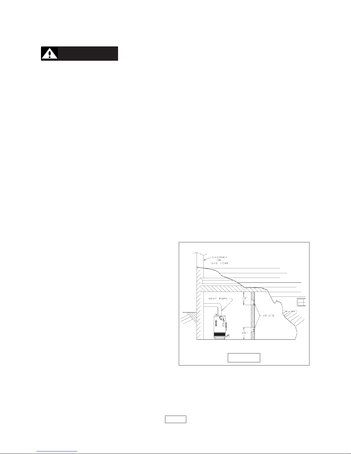
4. When air for combustion and ventilation
is from inside buildings, the confined space
shall be provided with two permanent
openings, one starting 12 inches from the top
and one 12 inches from the bottom of the
enclosed space. Each opening shall have a
minimum free area of 1 square inch per one thousand (1000) BTU per hour of the total input
rating of all appliances in the enclosed space, but must not be less than one hundred (100)
square inches. These openings must freely communicate directly with other spaces of
sufficient volume so that the combined volume of all spaces meets the criteria for an
unconfined space.
PAGE 3
FIGURE 1
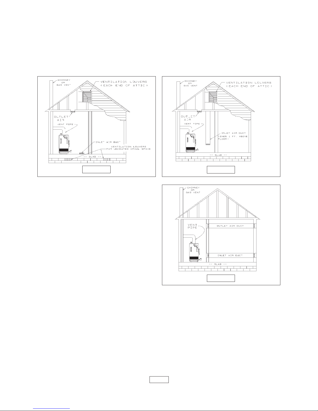
5. When the boiler is installed in a confined space and all air is provided from the outdoors
the confined space shall be provided with one or two permanent openings according to
methods A or B. When ducts are used, they shall be of the same cross sectional area as the
free area of the area of the openings to which they connect. The minimum dimension of
rectangular air ducts shall be not less than 3 x 3 inches or 9 square inches.
A. When installing two openings, one must commence within 12 inches from the top and
FIGURE 3FIGURE 2
the other within 12 inches from the bottom of
the enclosure. The openings shall
communicate directly, or by ducts, with the
outdoors or spaces (crawl or attic) that freely
communicate with the outdoors. One of the
following methods must be used to provide
adequate air for ventilation and combustion.
1. When directly communicating
with the outdoors, each opening shall have a
minimum free area of 1 square inch per 4,000
BTU per hour of total input rating of all
equipment in the enclosure. See figure 2
below.
2. When communicating with the
outdoors by means of vertical ducts, each
FIGURE 4
opening shall have a minimum free area 1
square inch per 4,000 BTU per hour of total input rating of all appliances in the enclosed
space. See figure 3 above.
3. If horizontal ducts are used, each opening and duct shall have a minimum free
area 1 square inch per 2,000 BTU per hour of total input rating of all appliances in the enclosed
space. See figure 4 at right.
B. One permanent opening, commencing within 12 inches of the top of the enclosure,
shall be permitted where the equipment has clearances of at least 1 inch from the sides, 1
inch from the back, and 6 inches from the front of the boiler. The opening shall directly
communicate with the outdoors or shall communicate through a vertical or horizontal duct to
the outdoors or spaces (crawl or attic) that freely communicate with the outdoors. The
openings must have a minimum free area of 1 square inch per 3000 Btu per hour of the total
PAGE 4
input rating of all equipment located in the enclosure. The free area must be no less than the
sum of the areas of all vent connectors in the confined space.
6. In calculating free area using louvers, grilles or screens for the above, consideration
shall be given to their blocking effect. Screens used shall not be smaller than 1/4 inch mesh.
If the free area through a design of louver or grill is known, it should be used in calculating
the size opening required to provide the free area specified. If the design and free area is
not known, it may be assumed that wood louvers will have 20-25% free area and metal
louvers and grilles will have 60-75% free area. Louvers and grilles should be fixed in the open
position or interlocked with the boiler so they are opened automatically during the boiler
operation.
CONNECTING SUPPLCONNECTING SUPPL
CONNECTING SUPPL
CONNECTING SUPPLCONNECTING SUPPL
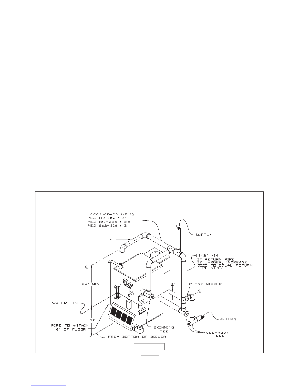
1. Suggested piping for steam heating system can be seen in figure 5 below. Actual
piping may vary based on system design and local conditions.
2. Suggested piping for a modular steam boiler using pumped returns may be seen in
figures 6a and 6b on page 6. Actual piping may vary based on system design and local
conditions.
3. Refer to pages 17 & 18 for procedures on cleaning and skimming off impurities.
4. "Near Boiler Piping" is crucial for proper performance of a replacement steam boiler
and should always be considered as part of the boiler installation. Always be sure to include
cleanout and skimming tees in the near boiler piping. These "Tees" are necessary for proper
cleaning and servicing of the boiler.
5. For further piping information refer to the I=B=R installation piping guide.
Y Y
AND RETURN PIPINGAND RETURN PIPING
Y
AND RETURN PIPING
Y Y
AND RETURN PIPINGAND RETURN PIPING
SUGGESTED PIPING FOR A SINGLE STEAM
BOILER HEATING SYSTEM
FIGURE 5
PAGE 5
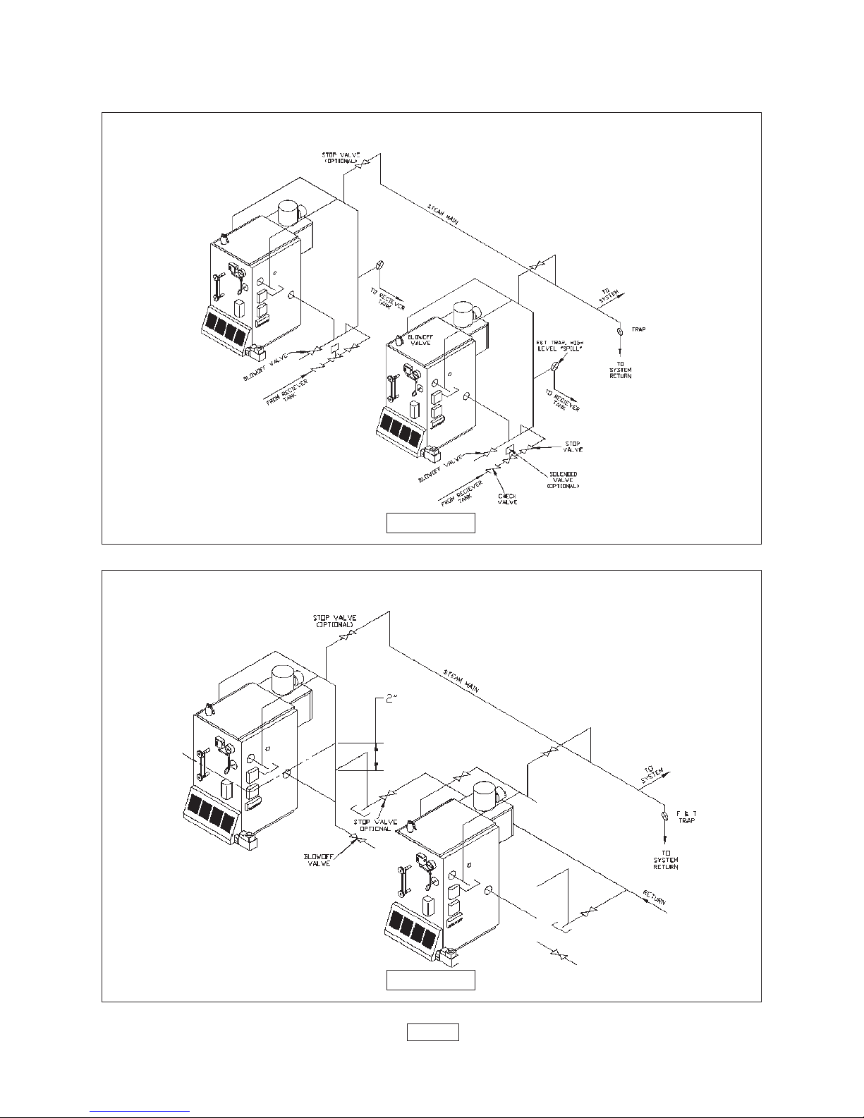
SUGGESTED PIPING FOR A MODULAR STEAM BOILERS
PUMPED RETURNS
FIGURE 6a
GRAVITY RETURNS
FIGURE 6b
PAGE 6

VENT INSTVENT INST
VENT INST
VENT INSTVENT INST
WW
ARNING:ARNING:
W
ARNING: This boiler shall not be connected to any portion of a mechanical
WW
ARNING:ARNING:
draft system operating under positive pressure.
1. The vent pipe must slope upward from the boiler not less than 1/4 inch for every 1 foot
to the vent terminal.
2. Horizontal portions of the venting system shall be supported rigidly every 5 feet and
at elbows. No portion of the vent pipe should have dips or sags.
3. This boiler series is classified as a Category 1 appliance and the vent installation shall
be in accordance with Part 7 & 11 of the latest revision of the National Fuel Gas Code or
applicable provisions of the local building codes.
4. Inspect chimney to make certain it is constructed according to National Board of Fire
Underwriters.
5. Attach draft hood to flue collector at rear of boiler, (See figure 7, below), with sheet
metal screw(s) through hole(s) provided. The vent or vent collector shall be Type B or metal
pipe having resistance to heat and corrosion not less than that of galvanized sheet steel or
aluminum not less than 0.016 inch thick (No. 28 GA).
ALLAALLA
ALLA
ALLAALLA
TIONTION
TION
TIONTION
6. Connect flue pipe same as draft hood to chimney. Bolt or screw joints together to avoid
sag. Flue pipe should not extend beyond inside wall of chimney. Do not install manual
damper in flue pipe or reduce size of flue outlet except as provided by the latest revision of
ANSI Z223.1. Protect combustible ceiling and walls near flue pipe with fireproof insulation.
Where two or more appliances vent into a common flue, the area of the common flue must
be at least equal to the area of the largest flue plus 50 percent of the areas of each additional
flue.
WARNING:WARNING:
WARNING:
WARNING:WARNING:
INSTALLATIONS OF BOILERSINSTALLATIONS OF BOILERS
INSTALLATIONS OF BOILERS
INSTALLATIONS OF BOILERSINSTALLATIONS OF BOILERS
AND VENTING SHOULD BEAND VENTING SHOULD BE
AND VENTING SHOULD BE
AND VENTING SHOULD BEAND VENTING SHOULD BE
DONE ONLY BY A QUALIFIEDDONE ONLY BY A QUALIFIED
DONE ONLY BY A QUALIFIED
DONE ONLY BY A QUALIFIEDDONE ONLY BY A QUALIFIED
EXPERT AND IN ACCORDANCEEXPERT AND IN ACCORDANCE
EXPERT AND IN ACCORDANCE
EXPERT AND IN ACCORDANCEEXPERT AND IN ACCORDANCE
WITH THE APPROPRIATEWITH THE APPROPRIATE
WITH THE APPROPRIATE
WITH THE APPROPRIATEWITH THE APPROPRIATE
COLUMBIA BOILERS MANUAL.COLUMBIA BOILERS MANUAL.
COLUMBIA BOILERS MANUAL.
COLUMBIA BOILERS MANUAL.COLUMBIA BOILERS MANUAL.
INSTALLING OR VENTING AINSTALLING OR VENTING A
INSTALLING OR VENTING A
INSTALLING OR VENTING AINSTALLING OR VENTING A
BOILER OR ANY OTHER GASBOILER OR ANY OTHER GAS
BOILER OR ANY OTHER GAS
BOILER OR ANY OTHER GASBOILER OR ANY OTHER GAS
APPLIANCE WITH IMPROPERAPPLIANCE WITH IMPROPER
APPLIANCE WITH IMPROPER
APPLIANCE WITH IMPROPERAPPLIANCE WITH IMPROPER
METHODS OR MATERIALS MAYMETHODS OR MATERIALS MAY
METHODS OR MATERIALS MAY
METHODS OR MATERIALS MAYMETHODS OR MATERIALS MAY
RESULT IN SERIOUS INJURYRESULT IN SERIOUS INJURY
RESULT IN SERIOUS INJURY
RESULT IN SERIOUS INJURYRESULT IN SERIOUS INJURY
OR DEATH DUE TO FIRE OR TOOR DEATH DUE TO FIRE OR TO
OR DEATH DUE TO FIRE OR TO
OR DEATH DUE TO FIRE OR TOOR DEATH DUE TO FIRE OR TO
ASPHYXIATION FROMASPHYXIATION FROM
ASPHYXIATION FROM
ASPHYXIATION FROMASPHYXIATION FROM
POISONOUS GASES SUCH ASPOISONOUS GASES SUCH AS
POISONOUS GASES SUCH AS
POISONOUS GASES SUCH ASPOISONOUS GASES SUCH AS
CARBON MONOXIDE WHICH ISCARBON MONOXIDE WHICH IS
CARBON MONOXIDE WHICH IS
CARBON MONOXIDE WHICH ISCARBON MONOXIDE WHICH IS
ODORLESS AND INVISIBLE.ODORLESS AND INVISIBLE.
ODORLESS AND INVISIBLE.
ODORLESS AND INVISIBLE.ODORLESS AND INVISIBLE.
ALLALL
ALL
ALLALL
FIGURE 7
PAGE 7
 Loading...