

Columbia CDVB SERIES Installation, Operation & Maintanance Manual
CDVB SERIES
Gas Fired Boilers For Forced Hot Water
INSTALLATION, OPERATION &
MAINTANANCE MANUAL
Co l u m b i a bo i l e r Co m p a n y
Main ofces and Factory: Pottstown, PA
P/N 37616101, Rev. C [02/09]
GAS FIRED BOILERS FOR FORCED HOT WATER
H
KEEP THIS MANUAL NEAR BOILER AND
RETAIN FOR FUTURE REFERENCE.
TABLE OF CONTENTS
Introduction ..........................................................................................................................................4
Boiler Ratings, Capacities & Dimensions ............................................................................................5
Ventilation & Combustion Air ...............................................................................................................7
Connecting Supply & Return Piping ..................................................................................................10
Applicable Federal Codes ................................................................................................................. 13
Vent System Modication ..................................................................................................................13
Connecting Gas Service ....................................................................................................................14
Electrical Wiring .................................................................................................................................15
Lighting Instructions...........................................................................................................................17
Sequence of Operations ....................................................................................................................18
General Instruction For Seasonal Startup & Maintenance ................................................................ 19
Replacement Parts ............................................................................................................................22
IMPORTANT: Read the following instructions
COMPLETELY before installing!
SAFETY SYMBOLS
The following dened symbols are used throughout this manual to notify the reader of potential hazards of varying
risk levels.
DANGER
!
Indicates an imminently hazardous situation
which, if not avoided, will result in death, serious
injury or substantial property damage.
CAUTION
!
Indicates a potentially hazardous situation which,
if not avoided, could result in minor or moderate
injury or property damage.
Indicates a potentially hazardous situation which,
if not avoided, could result in death, serious
injury or substantial property damage.
Indicates special instructions on installation,
operation or maintenance which are important
but not related to personal injury hazards.
WARNING
!
NOTICE
C.S.A. Certied for
Natural gas or Propane
Tested for 100 lbs.
ASME Working Pressure
2
INTRODUCTION
WARNING
!
1. Keep boiler area clear and free from combustible
materials, gasoline and other ammable vapors
and liquids.
2. DO NOT obstruct air openings to the boiler
room.
3. Modication, substitution or elimination of factory
equipped, supplied or specied components may
result in property damage, personal injury or the
loss of life.
4. TO THE OWNER: Installation and service of
this boiler must be performed by a qualified
installer.
5. TO THE INSTALLER: Leave all instructions with
the boiler for future reference.
6. When this product is installed in the Commonwealth of Massachusetts the installation
must be performed by a Licensed Plumber
or Licensed Gas Fitter.
5.
Allow 24 inches at the front and right side for servicing
and cleaning.
6.
When installed in utility room, the door should be wide
enough to allow the largest boiler part to enter, or to
permit replacement of another appliance such as a water
heater.
7.
The boiler shall be installed such that the gas ignition
system components are protected from water, (dripping,
spraying, rain, etc.), during appliance operation and
service, (circulator replacement, condensate trap, control
replacement, etc.).
8.
FOR INSTALLATION ON NON-COMBUSTIBLE FLOORS
ONLY. *The boiler must not be installed on carpeting.
Minimum clearances to combustible constructions are:
TOP ...................................................... 18 IN.
FRONT .....................................................6 IN.
FLUE CONNECTOR ...............................6 IN.
REAR ........................................................4 IN.
CONTROL SIDE .......................................9 IN.
WARNING
!
Improper installation, adjustment, alteration,
service or maintenance can cause injury or
property damage.
The installation must conform to the requirements of
1.
the authority having jurisdiction or, in absence of such
requirements, to the latest revision of the National Fuel
Gas Code, ANSI Z223-1. (Available from the American
Gas Association, Pleasant Valley Road, Cleveland, Ohio
44134.) Reference should also be made to local gas utility
regulations and other codes in effect in the area in which
the installation is to be made.
2.
Where required by the authority having jurisdiction, the
installation must conform to American Society of Mechanical Engineers Safety Code for Controls and Safety
Devices for Automatically Fired Boilers, ANSI/ASME No.
CSD-1.
3.
This boiler is classied as a Category I and III and vent
installation shall be in accordance with the latest revision
of the National Fuel Gas Code, ANSI Z223.1 or applicable
provisions of the local building codes.
OTHER SIDE ...........................................3 IN.
VENT PIPE ..............................................6 IN.
NOTES:
• Greater clearances for access should supersede re protection clearances.
* For installation on combustible ooring Special Base MUST
BE USED. (See Replacement Parts Section)
4.
LOCATE BOILER on level, solid base as near the outside
wall as possible and centrally located with respect to the
heat distribution system as practicable.
3
BOILER RATINGS, CAPACITIES & DIMENSIONS
WARNING
!
ALL INSTALLATIONS OF BOILERS AND VENTING SHOULD BE DONE ONLY BY A QUALIFIED
EXPERT AND IN ACCORDANCE WITH THE APPROPRIATE UTICA BOILERS MANUAL. INSTALLING OR VENTING A BOILER OR ANY OTHER GAS APPLIANCE WITH IMPROPER METHODS OR
MATERIALS MAY RESULT IN SERIOUS INJURY OR DEATH DUE TO FIRE OR TO ASPHYXIATION
FROM POISONOUS GASES SUCH AS CARBON MONOXIDE WHICH IS ODORLESS AND INVISIBLE.
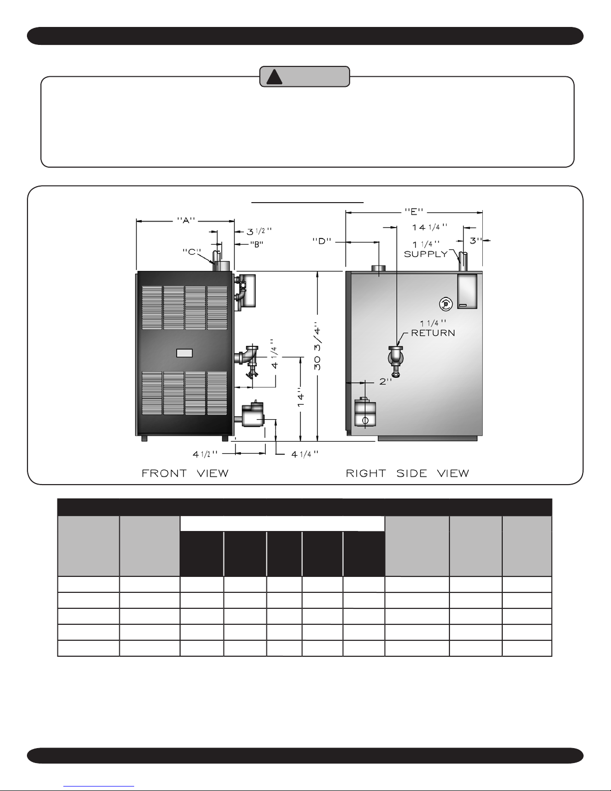
BOILER DIMENSIONS
Model #
-50 ½" 11¼ 2⅛ 3 6⅜ 27 1¼" 1 83%
-100 ½" 15⅛ 4⅛ 3 6⅜ 27 1¼" 2 82%
-125 ½" 19 6 3 6⅜ 27 1¼" 3 82%
-150 ½" 19 6 4 6⅜ 27 1¼" 3 80%
-200 ½" 22⅞ 8 4 7 28 1¼" 4 80%
NOTE: For altitudes above 2,000 ft. ratings should be reduced at the rate of 4% for each 1,000 ft. above sea level.
Natural
Gas Inlet
A B C D E
DIMENSIONS FOR NATURAL GAS
Dimensions
4
Pump size
Supply
& Return
Tappings
Number
of
Burners
AFUE
Ratings
BOILER RATINGS, CAPACITIES & DIMENSIONS
A.G.A.
Model #
-50 50,000 42,000 37,000 1 2.4 83%
-100 100,000 82,000 71,000 2 4.0 82%
-125 125,000 103,000 90,000 3 5.6 82%
-150 150,000 122,000 106,000 3 5.6 80%
-200 199,999 160,000 139,000 4 7.2 80%
Input
Btu/Hr.
Heating
Capacity
Btu/Hr.
I=B=R
NetOutput
Btu/Hr
No.
of
Burners
Water
Content
(Gals.)
AFUE
Ratings
STANDARD EQUIPMENT: Boiler Jacket, Cast Iron Boiler Battery, Combination Aquastat Relay, Theraltimeter
Gauge, Circulator, Main Gas Burners, Electric Ignition System, A.S.M.E relief Valve, Drain Valve, Induced Draft
Fan, and Safety Pressure Switch
All boilers are design certied for installation on non-combustible oors. For installation on combustible oors, use
combustible oor kit.
This boiler is a Category III Designed Certied appliance which requires a special horizontal through the wall venting
system. Only HEAT-FAB SAF-T-VENT™, FLEX-L STAR-34™, ProTech™ FasNSeal, and Z-FLEX Z-VENT™ vent
material products shall be used.
Should a chimney installation be required, see venting addendum.
See venting addendum for maximum vent lengths and proper congurations.
MEA number for the boilers is 415-90-E.
Electric service to be 120 Volts, 15 Amps, 60 Hz.
**For equivalent square feet of radiation, divide I=B=R output by 150.
5

VENTILATION & COMBUSTION AIR
WARNING
! !
AIR OPENINGS TO COMBUSTION AREA MUST NOT BE OBSTRUCTED.
BY FOLL O WING T HE I N STRUCTION S BEL O W, A DEQUATE
COMBUSTION AIR CAN BE MAINTAINED.
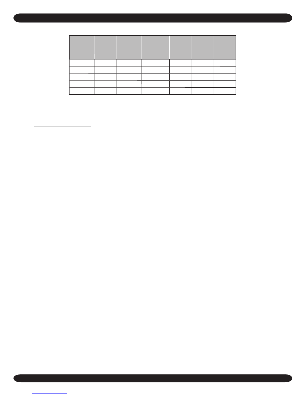
COMBUSTION AIR REQUIREMENTS
(Minimum Square Inch Openings)
*UNCONFINED AREA **CONFINED AREA
INSIDE
OUTSIDE
MODEL #
-50 10 100 13 25
-100 20 100 25 50
-125 25 125 32 63
-150 30 150 38 75
-200 40 200 50 100
COMBUSTION AIR
1 SQ. IN/5000 BTU/
HR (SEE Figure #2)
COMBUSTION AIR
1 SQ. IN. /1000
BTU/HR
(SEE Figure #1)
* Unconned Area: A space whose
volume is not less than 50 cubic feet
per 1000 BTU per hour of all appliances
installed in that space (cubic feet of space
= height x width x length).
** Conned Area: A space whose volume
is less than 50 cubic feet per 1000 BTU
per hour of all appliances installed in that
space (cubic feet of space = height x width
x length).
Ventilation of the boiler room must be adequate to
1.
provide sufcient air to properly support combustion
per the latest revision of the National Fuel Gas Code,
ANSI Z223.1.
2.
When a boiler is located in an unconned space in a
building or conventional construction frame, masonry
or metal building, inltration normally is adequate to
provide air for combustion and ventilation. However, if
the equipment is located in a building of tight construction
(See the National Fuel Gas Code, ANSI Z223.1 latest
OUTSIDE COMBUSTION AIR
VERTICAL
DUCTS 1 SQ. IN.
/4000 BTU/HR
(SEE Figures #2
& 3)
revision), the boiler area should be considered as a con-
ned space. In this case air for combustion and ventilation
shall be provided according to paragraph #5. If there is
any doubt, install air supply provisions in accordance with
the latest revision of the National Fuel Gas Code.
When a boiler is installed in an unconned space, in a
3.
building of unusually tight construction, air for combustion and ventilation must be obtained from outdoors or
from spaces freely communicating with the outdoors.
A permanent opening or openings having a total free
area of not less than 1 square inch per 5,000 BTU per
hour of total input rating of all appliances shall be pro-
vided. Ducts may be used to convey makeup air from
the outdoors and shall have the same cross-sectional
area of the openings to which they are connected.
4.
When air for combustion and ventilation is from inside
HORIZONTAL
DUCTS 1 SQ. IN.
/2000 BTU/HR
(SEE Figure #4)
6
VENTILATION & COMBUSTION AIR
VENT PIPE
BASEBOARD
VENTS
BOILER
12"
12"
OUTLET
AIR
VENTILATION LOUVERS
(EACH END OF ATTIC)
INLET
AIR
VENTILATION
LOUVRES FOR
UNHEATED
CRAWL SPACE
BOILER
OUTLET
AIR
VENTILATION LOUVERS
(EACH END OF ATTIC)
-- SLAB --
INLET AIR DUCT
12"
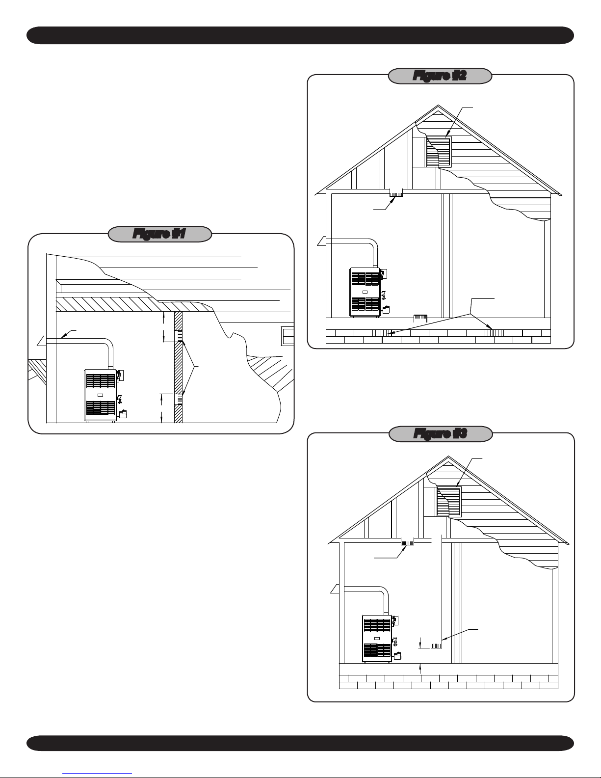
buildings, the conned space shall be provided with
two permanent openings, one starting 12 inches from the
top and one 12 inches from the bottom of the enclosed
space. Each opening shall have a minimum free area
of 1 square inch per one thousand (1000) BTU per hour
of the total input rating of all appliances in the enclosed
space, but must not be less than one hundred (100)
square inches. These openings must freely communicate
directly with other spaces of sufcient volume so that the
combined volume of all spaces meets the criteria for an
unconned space. See
Figure #1.
Figure #1
Figure #2
When the boiler is installed in a conned space and all air
5.
is provided from the outdoors the conned space shall be
provided with one or two permanent openings according
to methods A or B. When ducts are used, they shall be
of the same cross sectional area as the free area of the
area of the openings to which they connect. The minimum dimension of rectangular air ducts shall be not less
than 3 x 3 inches or 9 square inches.
When installing two openings, one must commence A.
within 12 inches from the top and the other within 12
inches from the bottom of the enclosure. The open-
ings shall communicate directly, or by ducts, with the
outdoors or spaces (crawl or attic) that freely commu-
nicate with the outdoors. One of the following methods
must be used to provide adequate air for ventilation
and combustion.
When communicating with the outdoors by means of II.
vertical ducts, each opening shall have a minimum
free area 1 square inch per 4,000 BTU per hour of
total input rating of all appliances in the enclosed
space. See
gure #3
.
Figure #3
(DUCT ENDS 1 FT.
ABOVE THE FLOOR)
When directly communicating with the outdoors, each I.
opening shall have a minimum free area of 1 square
inch per 4,000 BTU per hour of total input rating of all
equipment in the enclosure. See
Figure #2
.
7
BOILER
-- SLAB --
INLET AIR DUCT
12"
INLET AIR DUCT
12"
VENTILATION & COMBUSTION AIR
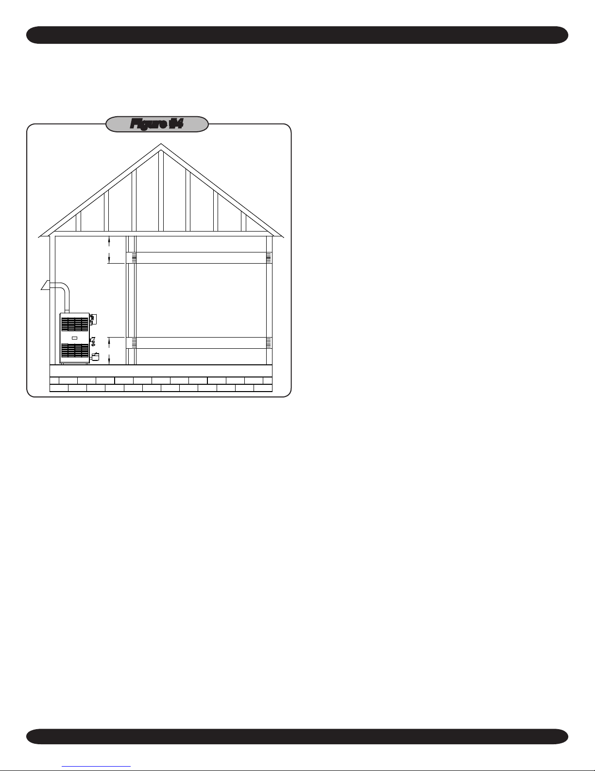
If horizontal ducts are used, each opening and duct III.
shall have a minimum free area 1 square inch per
2,000 BTU per hour of total input rating of all appli-
ances in the enclosed space. See
gure #4
.
Figure #4
In calculating free area using louvers, grilles or screens
6.
for the above, consideration shall be given to their block-
ing effect. Screens used shall not be smaller than 1/4 inch
mesh. If the free area through a design of louver or grill is
known, it should be used in calculating the size opening
required to provide the free area specied. If the design
and free area is not known, it may be assumed that wood
louvers will have 20-25% free area and metal louvers and
grilles will have 60-75% free area. Louvers and grilles
should be xed in the open position or interlocked with the
boiler so they are opened automatically during the boiler
operation.
One permanent opening, commencing within 12 inches B.
of the top of the enclosure, shall be permitted where the
equipment has clearances of at least 1 inch from the
sides, 1 inch from the back, and 6 inches from the front
of the boiler. The opening shall directly communicate
with the outdoors or shall communicate through a vertical or horizontal duct to the outdoors or spaces (crawl
or attic) that freely communicate with the outdoors. The
openings must have a minimum free area of 1 square
inch per 3000 Btu per hour of the total input rating of all
equipment located in the enclosure. The free area must
be no less than the sum of the areas of all vent connectors in the conned space.
8
CONNECTING SUPPLY & RETURN PIPING
CIRCULATOR
VAL VE
EXPANSION
TANK
VAL VE
RETURN
SUPPLY
12"
MAX.
CIRCULATOR
FLOW
VAL VE
SYSTEM
TEMPERATURE
GAUGE
"B"
"A"
SYSTEM
PRIMARY
6"
FEED
WATER
ZONE
CIR.
VAL V E
FLOW
VALVE
EXPANSION
TANK
VAL V E
SYSTEM
TEMPERATURE
GAUGE
RETURN
SUPPLY
"A"
"B"
6"
FEED
WATER
6"
EXPANSION
TANK
TEMPERATURE
SYSTEM
GAUGE
SUPPLY
RETURN
4 WAY MIXING
VALVE
ZONE
CIR.
WATER
FEED
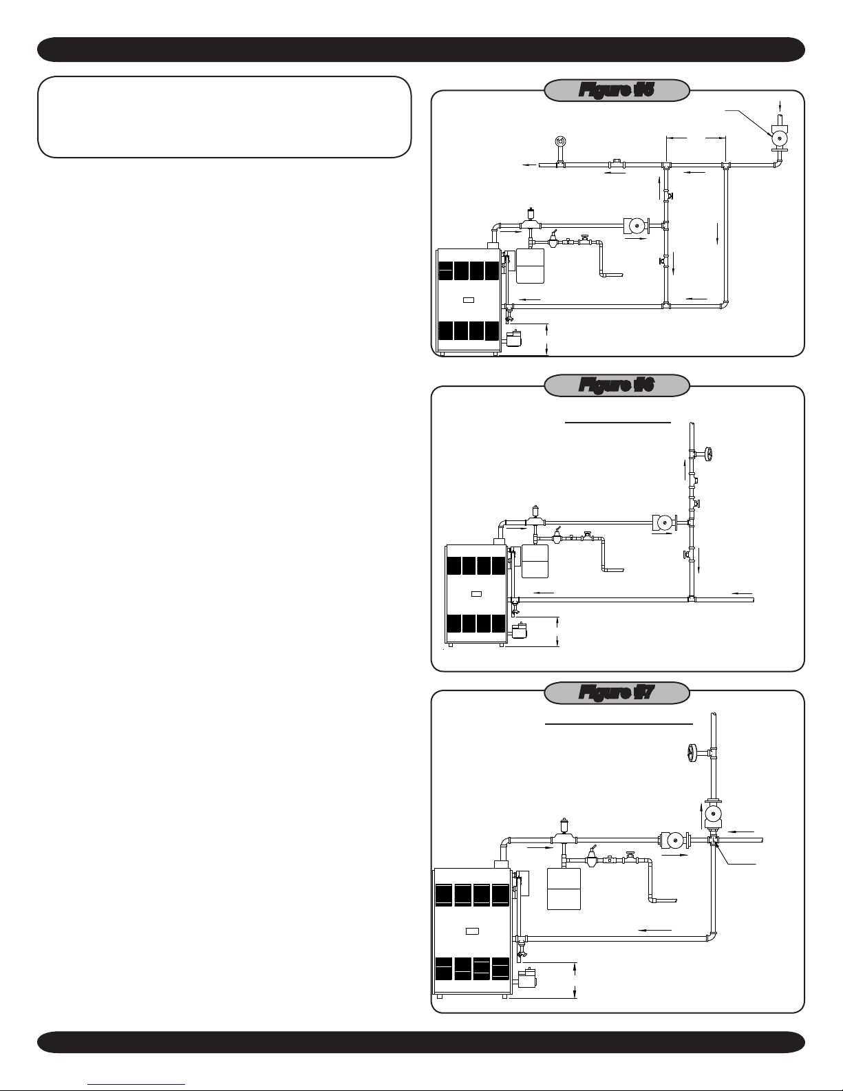
IMPORTANT: Circulators in the following
illustrations are mounted on the system supply
side, but mounting on the system return side is
also acceptable practice.
Connect supply and return piping as suggested in
1. gure
#5
, when the boiler is used in connection with refriger-
ated systems.
The chilled medium MUST BE PIPED IN PARALLEL A.
with the boiler.
Use appropriate valves to prevent the chilled medium B.
from entering the heating boiler.
During heating cycle open valves A and B, close I.
valves C and D.
During cooling cycle, open valves C and D, close II.
valves A and B.
C. Maintain a minimum clearance of one inch to hot C.
water pipes.
2.
When the boiler is connected to heating coils located in
air handling units where they may be exposed to refrigerated air circulation, the boiler piping system MUST
BE supplied with ow control valves or other automatic
means to prevent gravity circulation of the boiler water
during the cooling cycle.
Figure #5
Figure #6
BYPASS PIPING
3.
Hot water boilers installed above radiation level must be
provided with a low water cut-off device.
4.
When a boiler is connected to a heating system that
utilizes multiple zoned circulators, each circulator must
be supplied with a ow control valve to prevent gravity
circulation.
5.
Hot water boilers and system must be lled with water
and maintained to a minimum pressure of 12 pounds per
square inch.
6.
Bypass piping is an option which gives the ability to adjust
the supply boiler water temperature to t the system or
the condition of the installation. This method of piping,
however, is not typically required for baseboard heating systems. Typical installations where bypass piping is
used are as follows:
This method is used to protect boilers from conden-A.
sation forming due to low temperature return water.
Generally noticed in large converted gravity systems or
other large water volume systems. See
This method is used to protect systems using radiant B.
gure #6
.
panels and the material they are encased in from high
temperature supply water from the boiler. And protect
the boiler from condensate. See
gure #7
and
#8
.
Figure #7
MIXING VALVE PIPING
9
 Loading...