

Columbia CDVB-50, CDVB-150, CDVB-125, CDVB-100, CDVB-200 Installation, Operation & Maintenance Manual
CDVB SERIES
Gas Fired Boilers
For Forced Hot Water
INSTALL ATION, OPER ATION &
MAINTENANCE MANUAL
Columbia Company
Main ofces and Factory: Pottstown, PA
P/N 37616101, Rev. F [05/2012]
H
GAS FIRED BOILERS FOR FORCED HOT WATER
Introduction ................................................................................................................................ 3
Boiler Ratings, Capacities & Dimensions .......................................................................................... 4
Ventilation & Combustion Air ......................................................................................................... 6
Connecting Supply & Return Piping ................................................................................................ 7
Applicable Federal Codes .............................................................................................................11
Vent System Modication .............................................................................................................11
Horizontal Vent Pipe Installation Instructions ..................................................................................12
Vertical Vent Pipe Installation Instructions ......................................................................................22
Connecting Gas Service ...............................................................................................................28
Electrical Wiring .........................................................................................................................29
Lighting Instructions ...................................................................................................................31
Sequence Of Operation................................................................................................................32
General Instruction For Seasonal Startup & Maintenance ..................................................................33
Replacement Parts ......................................................................................................................37
KEEP THIS MANUAL NEAR BOILER AND
RETAIN FOR FUTURE REFERENCE.
IMPORTANT: Read the following instructions
COMPLETELY before installing!
SAFETY SYMBOLS
The following dened symbols are used throughout this manual to notify the reader of potential hazards of
varying risk levels.
DANGER
Indicates a hazardous situation which, if
!
not avoided, WILL result in death or serious
injury.
WARNING
Indicates a hazardous situation which, if
!
not avoided, could result in death or serious
injury.
Indicates a hazardous situation which, if not
!
avoided, may result in minor or moderate
injury.
Indicates information which should be
followed to ensure proper installation and
operation.
CAUTION
NOTICE
C.S.A. Certied for
Natural gas or Propane
Tested for 100 psi. ASME
Working Pressure
2

WARNING
1. Keep boiler area clear and free from
combustible materials, gasoline and other
ammable vapors and liquids.
2. DO NOT obstruct air openings to boiler
room.
3. Modication, substitution or elimination
of factory equipped, supplied or specied
components may result in property damage,
personal injury or loss of life.
!
4. To owner: Installation and service of this
boiler must be performed by qualied installer.
5. To installer: Leave all instructions with
boiler for future reference.
6. Boiler installation must conform to
Commonwealth of Massachusetts code 248
CMR when installed in Commonwealth of
Massachusettes. This includes, but is not
limited to, installation by licensed plumber or
gas tter.
INTRODUCTION
7.
Install boiler such that gas ignition system components
are protected from water, (dripping, spraying,
rain, etc.), during appliance operation and service,
(circulator replacement, condensate trap, control
replacement, etc.).
8.
Requirements for Commonwealth of
Mas sachusetts: Boiler installation must conform to
Commonwealth of Massachusetts code 248 CMR which
includes but is not limited to installation by licensed
plumber or gas tter.
9.
FOR INSTALLATION ON NON-COMBUSTIBLE
FLOORS ONLY. *Boiler must NOT be installed on
carpeting.
10.
Minimum clearances to combustible constructions are:
TOP ...........................................18 in.
FRONT ........................................6 in
FLUE CONNECTOR .........................6 in
REAR............................................4 in.
CONTROL SIDE..............................9 in.
OTHER SIDE .................................3 in.
VENT PIPE ....................................6 in.
(457mm)
(152mm)
(152mm)
(102mm)
(229mm)
(76mm)
(152mm)
NOTICE
WARNING
Improper installation, adjustment, alteration,
!
service or maintenance can cause injury or
property damage.
1.
Installation must conform to requirements of authority
having jurisdiction or, in absence of such requirements,
to the National Fuel Gas Code, ANSI Z223.1/NFPA 54
and/or Natural Gas and Propane Installation Code,
CAN/BS149.1
2.
Where required by the authority having jurisdiction,
installation must conform to Standard for Controls and
Safety Devices for Automatically Fired Boilers, ANSI/
ASME No. CSD-1.
3.
This boiler is classied as Category I and III and vent
installation shall be in accordance with latest revision of
the National Fuel Gas Code, ANSI Z223.1 or applicable
provisions of the local building codes.
4.
LOCATE BOILER on level, solid base as near outside
wall as possible and centrally located with respect to
heat distribution system as practicable.
5.
Allow 24 inches at front and right side for servicing and
cleaning.
6.
When installed in utility room, door should be wide
enough to allow largest boiler part to enter, or to
permit replacement of another appliance such as a
water heater.
• Greater clearances for access should
supersede re protection clearances.
* For installation on combustible ooring
Special Base MUST BE USED. (See
Replacement Parts Section)
3

All installations of boilers and venting should be done only by a qualied expert and in accordance with
!
the appropriate utica boilers manual. Installing or venting a boiler or any other gas appliance with
improper methods or materials may result in serious injury or death due to re or to asphyxiation from
poisonous gases such as carbon monoxide which is odorless and invisible.
Figure 1 -Boiler Dimensions
BOILER RATINGS, CAPACITIES & DIMENSIONS
WARNING
Table 1- DIMENSIONS FOR NATURAL GAS
Model #
-50
-100
-125
-150
-200
NOTE:
each 1,000 ft. above sea level.
For altitudes above 2,000 ft. ratings should be reduced at the rate of 4% for
Natural
Gas Inlet
½"
½"
½"
½"
½"
Dimensions
A B C D
11¼
15⅛
19
19
22⅞
2⅛
4⅛
6
6
8
3
3
3
4
4
4
6⅜
6⅜
6⅜
6⅜
7
E
27
27
27
27
28
Pump
size
Supply &
Return
Tappings
1¼"
1¼"
1¼"
1¼"
1¼"

BOILER RATINGS, CAPACITIES & DIMENSION
Table 2 - RATINGS AND CAPACITIES
Model #
-50
-100
-125
-150
-200
(1)
Mbh = 1000 Btu per hour
(2)
Net Water Ratings shown based on piping and pickup allowance of 1.15.
Input
Btu/hr
50,000
100,000
125,000
150,000
199,999
Heating
Capacity
(1)
Mbh
42
82
103
122
160
Net
Rating
Water,
Mbh
37
71
90
1060
139
AFUE
(1)
(2)
83.0%
82.0%
82.0%
80.0%
80.0%
No.
of
Burners
1
2
3
3
4
Water
Content
(Gals.)
2.4
4.0
5.6
5.6
7.2
Contact manufacturer before selecting boiler for installations having unusual
piping and pickup requirements, such as intermittent system operation,
extensive piping systems, etc.
STANDARD EQUIPMENT: Boiler Jacket, Cast Iron Boiler Battery, Combination Aquastat Relay, Theraltimeter Gauge,
Circulator, Main Gas Burners, Electric Ignition System, A.S.M.E relief Valve, Drain Valve, Induced Draft Fan, and Safety
Pressure Switch
All boilers are design certied for installation on non-combustible oors. For installation on combustible oors, use
combustible oor kit.
Boiler is Category III Designed Certied appliance which requires a special horizontal through the wall venting system.
Only HEAT-FAB SAF-T-VENT™, FLEX-L STAR-34™, ProTech™ FasNSeal, and Z-FLEX Z-VENT™ vent material products
shall be used.
Electric service to be 120 Volts, 15 Amps, 60 Hz.
5
VENTILATION & COMBUSTION AIR
Provide combustion air and ventilation air in accordance
with the section “Air for Combustion and Ventilation,” of the
National Fuel Gas Code, ANSI Z223.1/NFPA 54, or Sections
8.2, 8.3 or 8.4 of Natural Gas and Propane Installation
Code, CAN/CSA B149.1, or applicable provisions of local
building codes.
Provide make-up air where exhaust fans, clothes dryers,
and kitchen ventilation equipment interfere with proper
operation.
National Fuel Gas Code recognizes several methods
of obtaining adequate ventilation and combustion air.
Requirements of the authority having jurisdiction may
override these methods.
• Engineered Installations. Must be approved by
authority having jurisdictions.
• Mechanical Air Supply. Provide minimum of 0.35
cfm per Mbh for all appliances located within space.
Additional requirements where exhaust fans installed.
Interlock each appliance to mechanical air supply
system to prevent main burner operation when
mechanical air supply system not operating.
• All Indoor Air. Calculate minimum volume for all
appliances in space. Use a different method if
minimum volume not available.
о Standard Method. Cannot be used if known air
inltration rate is less than 0.40 air changes per
hour. See Table 3 for space with boiler only. Use
equation for multiple appliances.
Volume ≥ 50 ft3 x Total Input [Mbh]
о Known Air Inltration Rate. See Table 3 for
space with boiler only. Use equation for multiple
appliances. Do not use an air inltration rate
(ACH) greater than 0.60.
Volume ≥ 15 ft3/ACH x Total Input [Mbh]
о Refer to National Fuel Gas Code for opening
requirements between connection indoor spaces.
National Gas and Propane Installation Code Requires
providing air supply in accordance with:
• All Outdoor Air. Provide permanent opening(s)
communicating directly or by ducts with outdoors.
о Two Permanent Opening Method. Provide opening
commencing within 12 inches of top and second
opening commencing within 12 inches of bottom
enclosure.
Direct communication with outdoors or
communicating through vertical ducts. Provide
minimum free area of 1 in2 per 4 Mbh of total
input rating of all appliances in enclosure.
Communicating through horizontal ducts.
Provide minimum free area of 1 in2 per 2
Mbh of total input rating of all appliances in
enclosure.
о One Permanent Opening Method. Provide opening
commencing within 12 inches of top of enclosure.
Provide minimum clearance of 1 inch on sides
and back and 6 inches on front of boiler (does not
supersede clearance to combustible materials).
о Combination Indoor and Outdoor Air. Refer to
National Fuel Gas Code for additional requirements
for louvers, grilles, screens and air ducts.
• Combination Indoor and Outdoor Air. Refer to
National Fuel Gas Code for application information.
• Section 8.2 and 8.3 when combination of appliances
has a total input of up to and including 400 Mbh (120
kW).
о Does not have draft control device.
• Section 8.4 when combination of appliances has total
input exceeding 400 Mbh (120 kW).
• Refer to Natural Gas and Propane Installation Code
for specic air supply requirements for enclosure
or structure where boiler is installed, including air
supply openings and ducts.
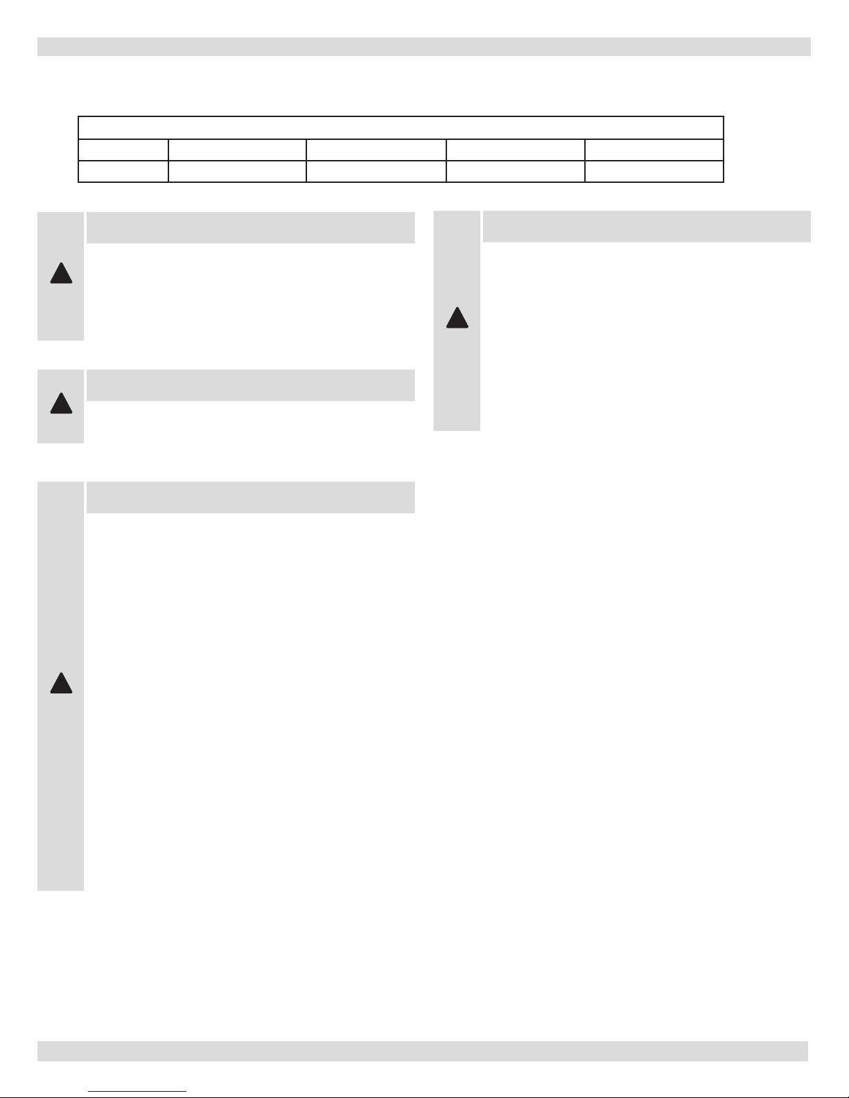
Table 3
Input Mbh
50 2500 7500 3750 2500 1875 1500 1250
100 5000 15000 7500 5000 3750 3000 2500
125 6250 18750 9375 6250 4688 3750 3125
150 7500 22500 11250 7500 5625 4500 3750
200 10000 30000 15000 10000 7500 6000 5000
Standard
Method
0.1 0.2 0.3 0.4 0.5 0.6
Known Air Inltration Rate Method (Air Changes Per Hour)
6

CONNECTING SUPPLY & RETURN PIPING
IMPORTANT: Circulators in following illustrations
are mounted on system supply side, but mounting on
system return side is also acceptable practice.
1.
Maintain minimum clearance of one inch (25mm) to hot
water pipes.
2.
Boiler, when used in connection with refrigeration
system, must be installed so chilled medium is piped in
parallel with boiler with appropriate valves to prevent
chilled medium from entering boiler.
3.
Boiler piping system of hot water boiler connected to
heating coils located in air handling units where they
may be exposed to refrigerated air circulation must be
equipped with ow control valves or other automatic
means to prevent gravity circulation of boiler water
during cooling cycle.
4.
Hot water boiler installed above radiation level or as
required by the Authority having jurisdiction, must be
provided with low water cutoff device either as part of
boiler or at time of boiler installation.
5.
When boiler is connected to heating system that utilizes
multiple zoned circulators, each circulator must be
supplied with ow control valve to prevent gravity
circulation.
6.
Hot water boilers and system must be lled with water
and maintained to minimum pressure of 12 psi.
7.
Bypass piping is option which gives ability to adjust
supply boiler water temperature to t system or
condition of installation. This method of piping,
however, is not typically required for baseboard heating
systems. Typical installations where bypass piping is
used are as follows:
A. This method is used to protect boilers from
condensation forming due to low temperature
return water. Generally noticed in large converted
gravity systems or other large water volume
systems. See
B. This method is used to protect systems using
radiant panels and the material they are encased
in from high temperature supply water from boiler,
and protect boiler from condensate. See
and 4.
C. This method is used to protect boilers from
condensate forming as well as protecting heating
system from high water temperatures, see
4
.
gure 2
.
gure 3
gure
7
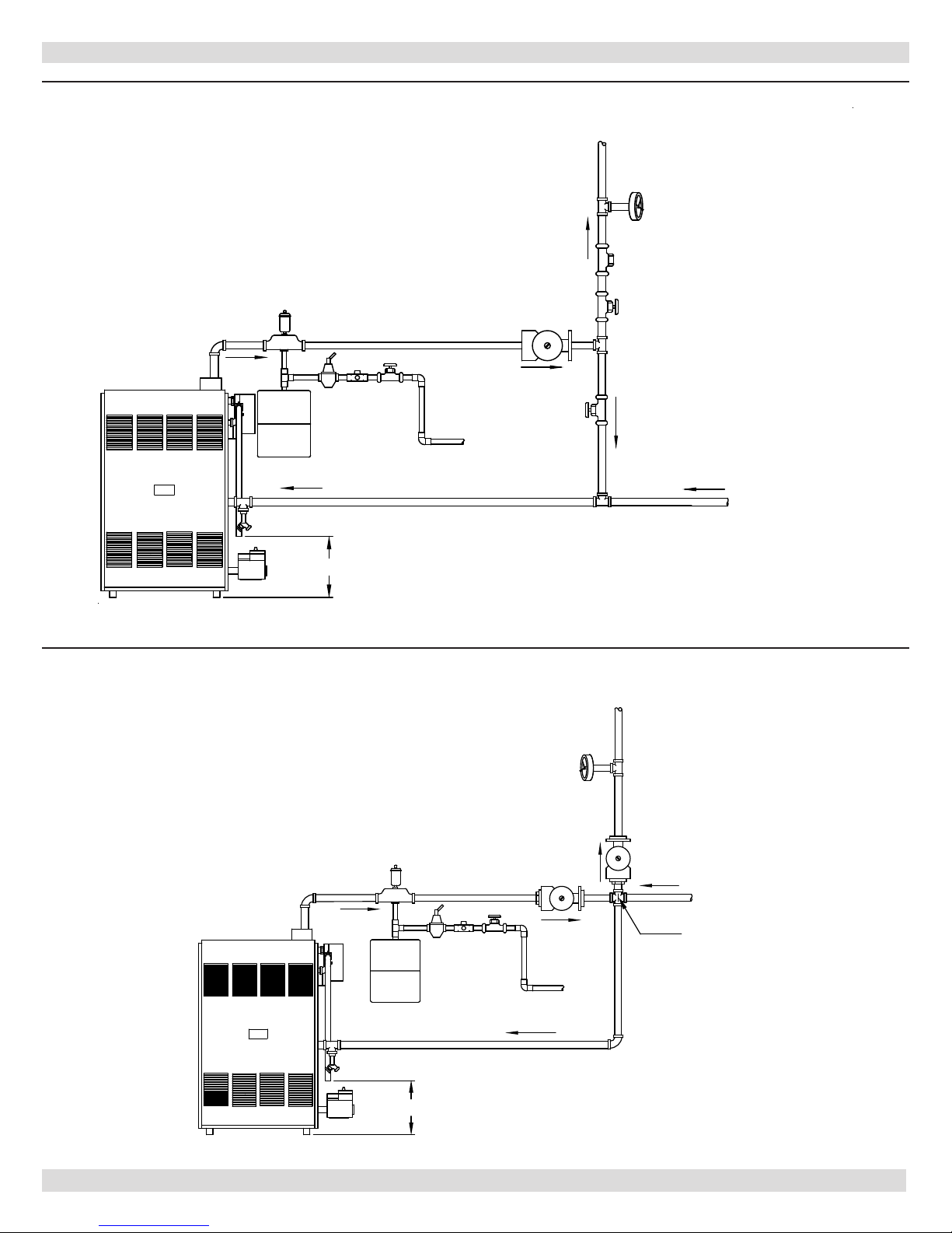
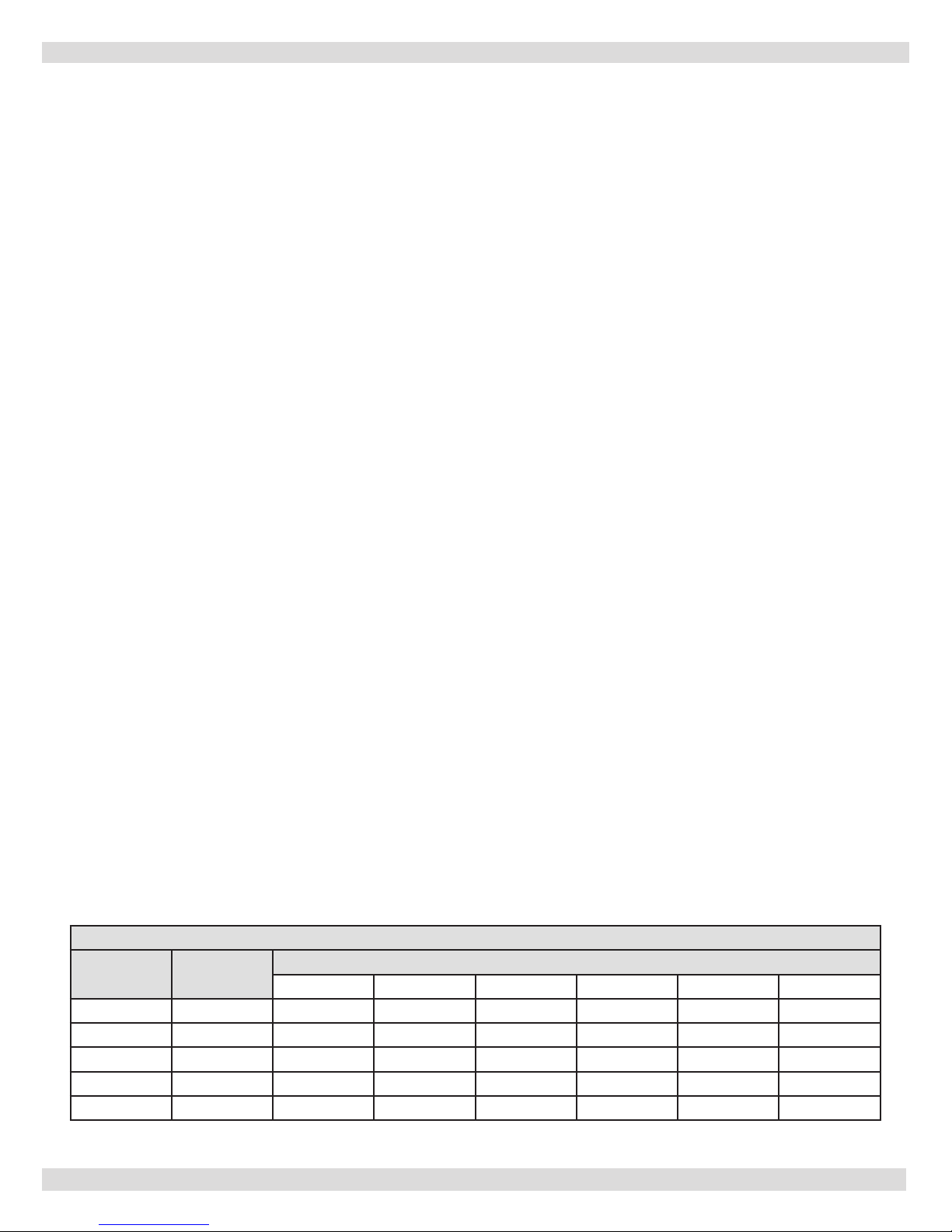
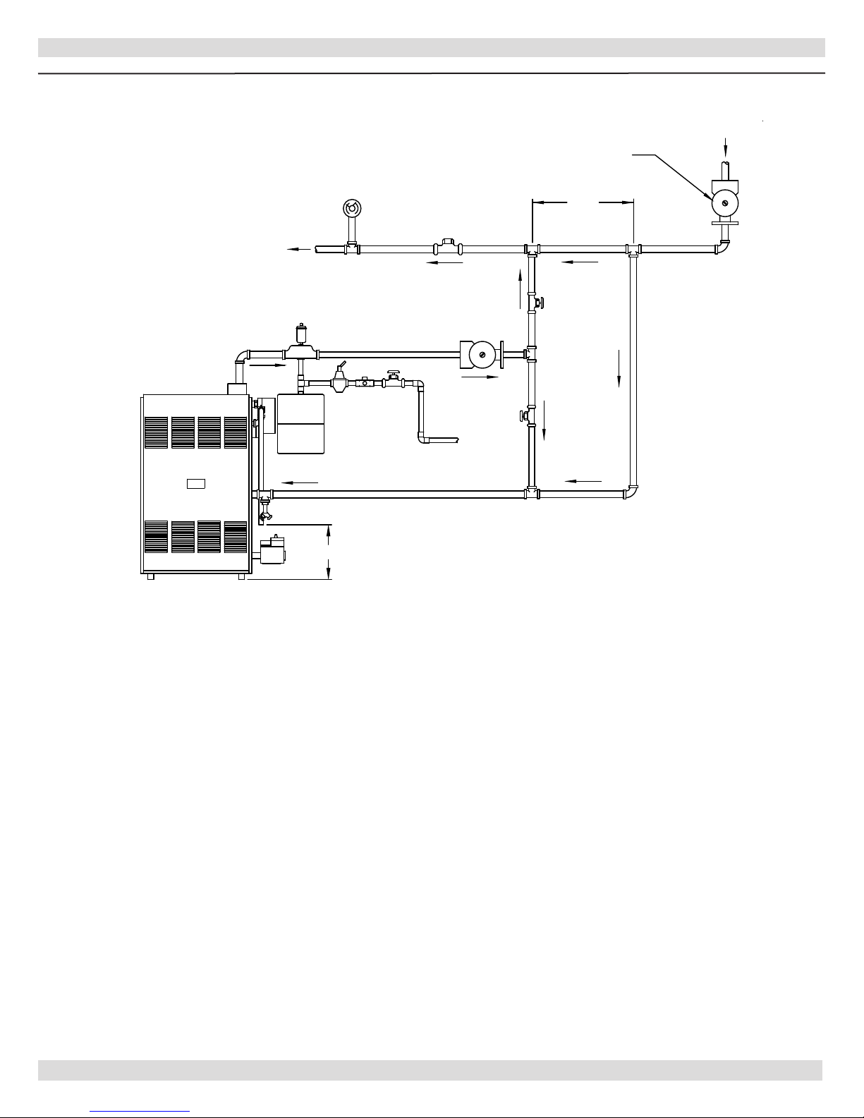
Figure 2 - BYPASS PIPING
CONNECTING SUPPLY & RETURN PIPING
SUPPLY
SYSTEM
TEMPERATURE
GAUGE
FLOW
VALVE
EXPANSION
TANK
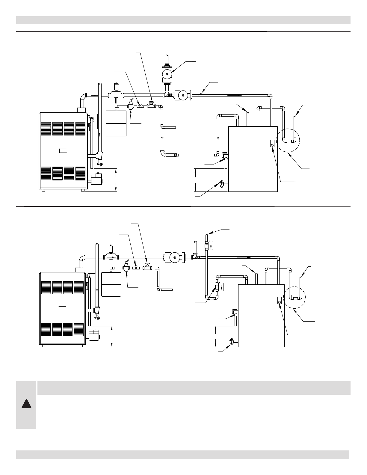
Figure 3 - MIXING VALVE PIPING
FEED
WATER
ZONE
CIR.
"B"
VALV E
"A"
VALV E
RETURN
6"
SUPPLY
EXPANSION
TANK
SYSTEM
TEMPERATURE
GAUGE
ZONE
CIR.
RETURN
4 WAY MIXING
VALV E
FEED
WATER
6"
8
CIRCULATOR
VALV E
EXPANSION
TANK
VALV E
RETURN
SUPPLY
12"
MAX.
CIRCULATOR
FLOW
VALV E
SYSTEM
TEMPERATURE
GAUGE
"B"
"A"
SYSTEM
PRIMARY
6"
FEED
WATER
CONNECTING SUPPLY & RETURN PIPING
Figure 4 - PRIMARY SECONDARY PIPING WITH BYPASS
NOTE #1: When using bypass piping, adjust
valves A and B until desired system temperature is
obtained.
NOTE #2: Bypass loop must be same size piping as
the supply and return piping.
8.
Installation using circulators is shown in
9.
Installation using zone valves is shown in
10.
For further piping information refer to the I=B=R
Installation and Piping Guide.
gure 5
gure 6
.
.
9

CONNECTING SUPPLY & RETURN PIPING
WARNING
To avoid burns, scalding, or water damage due to discharge of steam and/or hot water during operation, a
discharge line shall be installed to relief valve outlet connection.
Discharge line shall:
• connect to relief valve outlet and piped down to safe point of disposal. Check local codes for
maximum distance from oor or allowable safe point of discharge.
• be of pipe size equal to or greater than that of the relief valve outlet over the entire length of
discharge line;
• have no intervening shutoff valve between safety relief valve and discharge to atmosphere (do not
plug or place any obstruction in discharge line.
• terminate freely to atmosphere where any discharge will be clearly visible and at no risk of freezing;
• allow complete drainage of the valve and the discharge line;
• be independently supported and securely anchored to avoid applied stress on the relief valve;
• be as short and straight as possible;
• terminate with plain end (not threaded);
• be constructed of material suitable for exposure to temperatures of 375° F; or greater.
Refer to local codes and appropriate ASME Boiler and Pressure Vessel Code for additional installation
requirements.
WARNING
Burn and scald hazard. Safety relief valve
!
could discharge steam or hot water during
operation. Install discharge piping per these
instructions.
11.
Install discharge piping from safety relief valve.
• Use ¾" or larger pipe.
• Use pipe suitable for temperatures of 375°F (191°C)
or greater.
• Individual boiler discharge piping shall be independent
of other discharge piping.
• Size and arrange discharge piping to avoid reducing
safety relief valve relieving capacity below minimum
relief valve capacity stated on rating plate.
• Run pipe as short and straight as possible to location
protecting user from scalding and properly drain
piping.
• Install union, if used, close to safety relief valve outlet.
• Install elbow(s), if used, close to safety relief valve
outlet and downstream of union (if used).
• Terminate pipe with plain end (not threaded).
10
CIRCULATOR
DRAIN COCK
RELIEF VALVE
HOT WATER
OUTLET
THERMAL
TRAP
PUMP CONTROL
WIRING FOR
THERMOSTAT/
SYSTEM RETURN
PIPING
INLET
COLD WATER
VALV E
TANK ZONE
6"
6"
PRESSURE
REDUCING
VALV E
BACKFLOW PREVENTER
REDUCED PRESSURE
GATE VALVE
Figure 5 - Piping with Circulator
REDUCED PRESSURE
BACKFLOW PREVENTER
CONNECTING SUPPLY & RETURN PIPING
GATE
VALV E
SYSTEM
CIRCULATOR
FLOW CONTROL
OR CHECK VALVE
6"
Figure 6 - Piping with Zone Valves
PRESSURE
REDUCING
VALV E
TANK
CIRCULATOR
FEED
WATER
RELIEF VALVE
DRAIN COCK
COLD WATER
INLET
6"
HOT WATER
OUTLET
THERMAL
TRAP
WIRING FOR
THERMOSTAT/
PUMP CONTROL
All installations of boilers and venting should be done only by a qualied expert and in accordance
!
with the appropriate installation manual. Installing or venting a boiler or any other gas appliance with
improper methods or materials may result in serious injury or death due to re or to asphyxiation from
poisonous gases such as carbon monoxide which is odorless and invisible.
WARNING
11

APPLICABLE FEDERAL CODES
NFPA 54/ANSI Z223.1, National Fuel Gas Code and NFPA/
ANSI 211, Chimneys, Fireplaces, Vents and Solid Fuel
Burning Appliances. These codes contain information on
special gas vents for Category II, III and IV appliances,
vent sizing, location, air space clearances to combustibles
and safe installation practices. The gas vent installer
should be familiar with these Federal Codes as well as
Local Codes and Regulations.
General Information Gas Vents And Appliances:
By Federal Codes, gas appliances are categorized by
the pressure and temperature of the ue gas vented
from the appliance. Category I and II appliances are
natural draft (draft hood) vented, with high ue gas
temperatures (Category I), and low ue gas temperatures
(Category II). Category III and IV appliances are fan
forced vents with high temperature (Category III) and
low temperature (Category IV) ue gasses. Appliance
efciency is directly related to ue gas temperature.
Higher efciency appliances remove more heat from the
gas, so they will have lower temperature ue products.
VENT SYSTEM MODIFICATION
When ue gas temperatures are lowered, corrosive
condensates may form in the gas vent or in the appliance.
Condensates may form in Category II, III, IV appliance
vents, so special, corrosive resistant venting systems are
required for higher efciency appliances.
WARNING
Vents for Category I appliances may not be
!
suitable for use with Category II, III, or IV
appliances because condensate may corrode
the vent.
WARNING
Vents for Category III appliances may not be
!
suitable for use with Category I appliances
because ue gas temperatures may be too
high.
When an existing boiler is removed from a common venting
system, the common venting system is likely to be too
large for the proper venting of the appliances remained
connected to it. If this situation occurs, the following test
procedure must be followed:
REMOVAL OF BOILER FROM VENTING SYSTEM
At the time of removal of an existing boiler, the following
steps shall be followed with each appliance remaining
connected to the common venting system placed in
operation, while the other appliances remaining connected
to the common venting system are not in operation.
1.
Seal an unused opening in the common venting
system.
2.
Visually inspect the venting system for proper size and
horizontal pitch and determine there is no blockage or
restriction, leakage, corrosion and other deciencies
which could cause an unsafe condition.
3.
Insofar as is practical, close all building doors and
windows and all doors between the space in which the
appliances remaining connected to the common venting
system are located and other spaces of the building.
Turn on clothes dryers and any other appliance not
connected to the common venting system. Turn on
any exhaust fans, such as range hoods and bathroom
exhausts, so they operate at maximum speed. Do
not operate a summer exhaust fan. Close replace
dampers.
4.
5.
6.
7.
Place in operation the appliance being inspected. Follow
the lighting instructions. Adjust thermostat so appliance
will operate continuously.
Test for spillage at the draft hood relief opening after
5 minutes of main burner operation. Use the ame of
a match or candle, or smoke from a cigarette, cigar or
pipe.
After it has been determined that each appliance
remaining connected to a common venting system
properly vents when tested as outlined above, return
doors, windows, exhaust fans, replace dampers and
any other gas burning appliances to their previous
condition of use.
Any improper operation if the common venting system
should be corrected so the installation conforms with
the National Fuel Gas Code, ANSI Z223.1/NFPA 54,
and/or the Natural Gas and Propane Installation Code,
CAN/CSA B149.1. When resizing any portion of the
common venting system, the common venting system
should be resized to approach the minimum size as
determined using the appropriate tables in Chapter 13
of the National Fuel Gas Code, ANSI Z223.1/NFPA 54,
and/or the Natural Gas and Propane Installation Code,
CAN/CSA B149.1.
12
HORIZONTAL VENT PIPE INSTALLATION INSTRUCTIONS
Horizontal Vent Pipe Installation Instructions
(Through the wall)
This boiler is design certied for use with the following venting systems
Company HEAT-FAB
Product SAF-T-VENT™ STAR-34™ Z-VENT™ FasNSeal™
®
FLEX-L
CAUTION
The above vent pipe and ttings are used
for venting gas burning category III and
!
IV appliances. Do not use this vent pipe or
ttings for venting appliances burning fuels
such as wood, oil, kerosene or coal.
CAUTION
!
Do not use this vent pipe and ttings for
venting incinerators of any kind.
®
Z-FLEX
®
ProTech
®
WARNING
All installations of boilers and venting
should be done only by a qualied expert
and in accordance with the appropriate
manufacturers manual. Installing or venting
!
a boiler or any other gas appliance with
improper methods or materials may result
in serious injury or death due to re or to
asphyxiation from poisonous gases such
as carbon monoxide which is odorless and
invisible.
!
WARNING
1.
For correct installation of vent system,
read all of these instructions and refer to
the vent pipe manufacturer's instructions.
2.
Failure to use this venting system will void
the manufacturer’s warranty and may
result in rapid deterioration of the venting
system, a potential health hazard.
3.
Faulty vent installation can allow toxic
fumes to be released into living areas.
This may cause serious bodily injury or
property damage. Vent performance may
also be affected by improper assembly.
4.
Install separate vents for forced exhaust
appliances and natural draft appliances.
A common vent between natural draft
and forced exhaust appliances may cause
toxic gases to exhaust through the natural
draft appliance rather than to outside air.
Breathing exhaust gases will cause serious
personal injury or death.
13
HORIZONTAL VENT INSTALLATION INSTRUCTIONS
A. Boilers covered in this section are design-certied as
CATEGORY III for venting, only when installed with
manufacturer specied vent system components and
installation practices.
B. Install vent pipe beginning at the vent connector and
work toward the vent cap.
C. Vent pipe and ttings MUST NOT be routed into,
through, or within any other vent, such as an
existing masonry chimney or factory built chimney.
(Recommended installation is shown in gure 7a & 7b
page 14, unacceptable installation is shown in gure 8
page 14).
D. Vent pipe lengths. The maximum length is the
combined length of straight horizontal and vertical
runs, and the equivalent straight length of ttings. The
required lengths for each boiler are as follows:
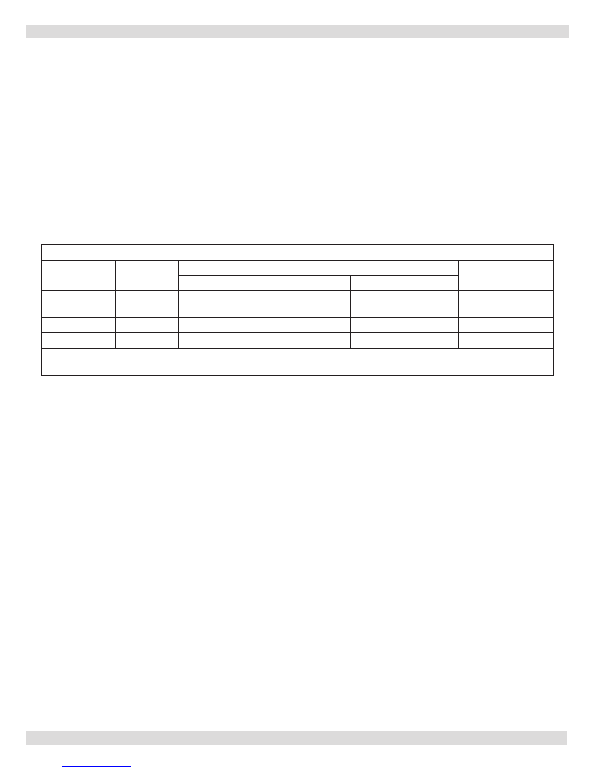
Vent Pipe Lenghts
Model
DV50/DV100 3" (7.6cm)
DV125 3" (7.6cm) 25 ft (7.6m) w/1 elbow 2 ft (0.6m) w/1 elbow 5 ft (1.5m)
DV150/200 4" (10.2cm) 30 ft (9.1m) w/1 elbow 2 ft (0.6m) w/1 elbow 5 ft (1.5m)
Example: 20 feet (6m) of vent pipe w/1 elbow is equivalent to 15 feet (4.6m) of vent pipe w/2 elbows.
Note: condensate trap is not required on models DV150 thru 200.
Vent Pipe
Diameter
Maximum Minimum
30 ft (9.1m) w/condensate Tee & 2
elbows
Vent Lengths
Equivalent Feet
Per Fitting
2 ft (0.6m) w/1 elbow 5 ft (1.5m)
E. Slope horizontal runs upwards not less than 1/4 inch/
foot (21mm/m) from boiler to vent terminal.
F. No portion of the vent pipe should have dips or sags
where condensate could collect, see gure 9 on page
14 for a typical vent system.
G. Rigidly support vent pipe every 5 feet and at the
elbows. Plumbers straps may be used.
H. Clearances and enclosures. ALL vent pipe and ttings
must be installed with appropriate air space clearances
to combustibles. These air space clearances apply
to indoor or outdoor vents, whether they are open,
enclosed, horizontal or vertical or pass through oors,
walls, roofs, or framed spaces. The appropriate air
space clearances should be observed to joists, studs,
suboors, plywood, drywall, or plaster enclosures,
insulated sheathing, rafters, roong, and any other
combustible material. The minimum air space clearance
also applies to electrical wires and any kind of building
insulation.
I. Do not insulate or otherwise wrap vent pipe or ttings.
J. For Horizontal runs maintain minimum clearance of
6 inches from vent pipe to any combustible material,
electric wires, and building materials.
14
 Loading...