

SCC5
SCC5----IR
SCC5SCC5
IR----DMX
DMX
IRIR
DMXDMX
Coloronix, Inc.
5461 West Jefferson Boulevard
Los Angeles, California 90016
(323) 677-4242
http://www.rgbw.com
SCC5
SCC5----RM
SCC5SCC5
RM----DMX
RMRM
DMX
DMXDMX

Coloronix, Inc.
2014 Coloronix, Inc. All rights reserved.
According to copyright laws, this manual may not be copied—partially, or wholly—
without the written consent of Coloronix, Inc.
Despite full effort to avoid any clerical or printing inaccuracies, Coloronix, inc. accepts
no responsibility for any such inaccuracies to be found in this manual.
Coloronix, Inc.
5461 West Jefferson Boulevard
Los Angeles, California 90016
Tech Support: (909) RGBW-555
http://www.rgbw.com
Coloronix and the Coloronix logo are brands of Coloronix, Inc.
Any non-Coloronix brands or products found in this manual are not endorsed, branded,
or recommended for use by Coloronix, Inc.; rather, they are only references for
informational purposes. Coloronix has no responsibility for these products in regards
to either performance or use.
Page 2—SCC5-IR-DMX / SCC5-RM-DMX Manual V.1.1

Contents
Contents
ContentsContents
Specifications
Specifications 4444
Specifications Specifications
Planning for Installation
Planning for Installation 4444
Planning for Installation Planning for Installation
Unpacking 4
Points to Consider About Data 4
Electrical Connection
Electrical Connection 5555
Electrical Connection Electrical Connection
Data Connection
Data Connection 6666
Data Connection Data Connection
Remote Control Interface 7
Remote Control Interface 7
Remote Control Interface 7Remote Control Interface 7
Troubleshooting Guide
Troubleshooting Guide 7777
Troubleshooting Guide Troubleshooting Guide
Further Troubleshooting 7
Page 3—SCC5-IR-DMX / SCC5-RM-DMX Manual V.1.1

Specifications
Specifications
SpecificationsSpecifications
Power Input: Direct 120VAC 50Hz/60Hz or 24VDC Option Available 0.15A Max.
Power Consumption: 2W
Temperature Rating: 0°F - 120°F Ambient
Planning f
Planning for Installation
Planning fPlanning f
or Installation
or Installation or Installation
Unpacking
The Color Ray Receiver and Remote Control is shipped assembled with no additional
assembly needed—they are shipped in separate packages.
Any optional accessories are included in the package. Use the packing list located on
the outside of the box to ensure all accessories are included.
Survey the unit to make sure the units are all intact—not cracked or damaged. Any
damages to the package or its contents are of the buyer’s responsibility; please follow
protocol for filing damage claims. Please recycle or appropriately discard of any
packing materials.
Points to Consider About Data
• Use a Belden 9481 or similar cable for DMX data connectivity or Plenum rated
CAT5 8-wire cable.
•
AC Power and DATA cables may NOT run in the same conduit due to possible
induced errors.
Page 4—SCC5-IR-DMX / SCC5-RM-DMX Manual V.1.1

Electrical Connection
Electrical Connection
Electrical ConnectionElectrical Connection
NOTE: Supply lead wires should not be connected to a dimmer of any sort.
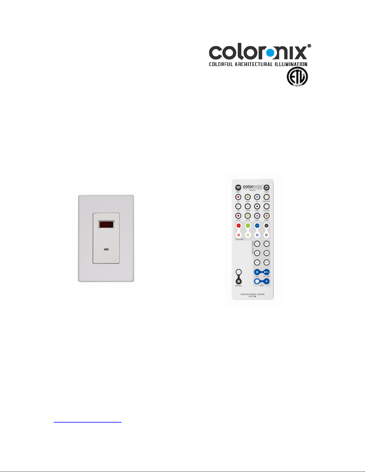
Installing Your SCC5-IR Receiver
1. Prepare Wires:
Note: Make sure the low-voltage wiring is installed at the wall box that will house the Color Ray
receiver.
• Be sure that the ends of the wires from the wall box are straight—cut if necessary.
• Remove 5/8” or 1.6 cm of insulation from each wire in the wall box.
2. Connect CAT5/RJ45 Cable to on board RJ45 jack.
3. Connect Power
Connect the line voltage (120V) wires in the following manner:
Screw the wire nuts clockwise so that no bare conductors show below the wire
connectors. Secure each connector with the electrical tape.
• Green dimmer Ground lead to Green or bare copper wire in wall box.
4. Test the Color Ray Receiver prior to mounting in wall box:
• Restore the power at the circuit breaker or fuse.
• Turn remote on to test.
• If the lights still do not turn on, refer to the troubleshooting section.
Note: set all fixtures to DMX address 1 (dip switch 1 in the UP position in Coloronix fixtures with Dip
Switches)
5. Mounting
1. Turn off the power at the circuit breaker or fuse.
2. Carefully position all wires so that there is room for the wall box for the dimmer.
3. Mount the dimmer into the box with the supplied mounting screws.
4. Attach the wallplate.
5. Complete the installation by restoring power at the circuit breaker or fuse.
Page 5—SCC5-IR-DMX / SCC5-RM-DMX Manual V.1.1

Data Connection
Data Connection
Data ConnectionData Connection
Fixtures on a serial data link must be daisy chained in one single line. To comply with the EIA-485
standard, no more than 32 fixtures should be connected on one data link. Connecting more than 32
fixtures on one serial data link without the use of a DATA optically-isolated splitter may result in
deterioration of the digital DMX signal.
Maximum recommended serial data link distance: 500 m (1640 ft)
Maximum recommended number of fixtures on a serial data link: 32
DMX Data Cable
If installer prefers 3-wire data cables, we suggest a Belden 9481 or equivalent cable which
meets the specifications for EIA RS-485 applications (Use PCL002 DMX hardwiring DMX
coupler). Standard microphone cables cannot transmit Color Ray signal reliably over long
distances. The cable must have the following characteristics:
Maximum capacitance between conductors:
30 pF/ft
Maximum capacitance between conductor and shield:
55 pF/ft
Maximum resistance: 20 ohms/1000 ft
Normal impedance: 100∼140 ohms
If installer prefers a RJ45/CAT5 Data installation, a RJ45 jack can be used.
Notice: To comply with all local codes and jurisdiction, qualified communications technicians
must do communications wiring.
Notice: Communication cables and AC power lines must not be run in the same conduit.
A. Route Data Cables in series between housing and any communications accessories
using DATA IN and DATA OUT.
B. In order that they may be easily accessed from the room once construction is
complete, secure data cables in the immediate proximity of the housings.
Coloronix strongly recommends clearly marking communication cables in such a way to
indicate the correct order of connection.
Type: shielded, 2-conductor twisted pair
Page 6—SCC5-IR-DMX / SCC5-RM-DMX Manual V.1.1

Remote Control Interface
Remote Control Interface
Remote Control InterfaceRemote Control Interface
Troubleshooting Guide
Troubleshooting Guide
Troubleshooting GuideTroubleshooting Guide
If light does not turn ON and ON/OFF LED does not turn on, check if:
Lamp is burned out.
Lamp neutral connection is not wired.
If does not light, check if:
Electrical power is not connected.
Electrical power is less than specific voltage.
Electrical power is greater than specified voltage.
If control operation flickers or is intermittent, check if:
Color Changing fixtures or final DMX device in daisy chain is not terminated.
DATA cable is damaged.
Further Troubleshooting
Should problems occur while using the product, unplug it at once and contact:
Coloronix, Inc.
Tech Support: (909) RGBW-555
support@coloronix.com
Page 7—SCC5-IR-DMX / SCC5-RM-DMX Manual V.1.1
 Loading...