

Danger:
5461 W. Jefferson Blvd. LA, CA 90016
Ph: 888-458-6368 Fax: 888-758-6368
http://www.coloronix.com
Always disconnect power
before wiring, or maintenance.
SAVE THESE INSTALLATION INSTRUCTIONS
INSTALLATION INSTRUCTIONS
GS Series
Fixture must be installed by a qualified electrician. Do not install in locations where water collects and/or stands for prolonged
periods of time. Fixture must always be installed according to local and national electrical codes, rules & regulations.
Warning: The joint MUST be sealed between the mounting surface (i.e. ... wall, ground, ceiling, etc.) and the luminaire
with an appropriate sealing / caulking compound to provide a watertight seal. Seal all opening(s)/conduit opening(s) from water
entry. Before service insure fixture is cool to touch. Always ensure that all gaskets and sealing surfaces are free of dirt and debris.
- CAUTION: Fixture MUST be installed to allow for drainage and prevention of water from collecting around and in the bottom of the block-out housing and housing of the
fixture and /or separate junction box (by others, as needed depending on the type of junction box used). A layer of gravel and/or additional drainage material (example:
sandstone, etc.) and/or drainage pipe and/or other system may be needed below and/or around the fixture to prevent water from collecting around and in the bottom of the
block-out housing, housing and cord. A separate wiring junction box(s) (by others) may be needed to
installing a block-out housing and then pouring water in the hole and to check for drainage and if needed add gravel and/or additional drainage material, or drainage pipe until
there is drainage before pouring cement and installing electrical and the housing and rest of the fixture.
- Install the rough-in-section (block out housing flush at finish grade level - grade finish) of earth, non-organic material or concrete only , and then install housing with stainless
steel faceplate. Make sure organic material is 12 inches away from fixture. Never install bottom of faceplate below or above finish grade level.
- Make sure to keep any and all debris as well as water, snow and/or ice (
stainless steel with a cleaner specifically designed for stainless steel. - Installation should not be done under high humidity (i.e. Rainy day or after rain, foggy weather... etc.). - If
moisture is observed in fixture, dry fixture thoroughly and operate lamp to remove moisture. - Periodically check lens for cracks, check lens silicone for cracks, worn, torn and/or if it
badly deformed and replace as needed with factory parts only. When installing faceplate center lens and gasket in fixture. - Periodically check screw tightness on trim ring that holds
the lens in place and tighten and clean lens as need.
and salt, etc.) off of top of fixture at all times! Keep glass lens & stainless steel trim clean at all times. Clean
READ AND UNDERSTAND
THESE INSTALLATION
INSTRUCTIONS BEFORE
INSTALLING FIXTURE!
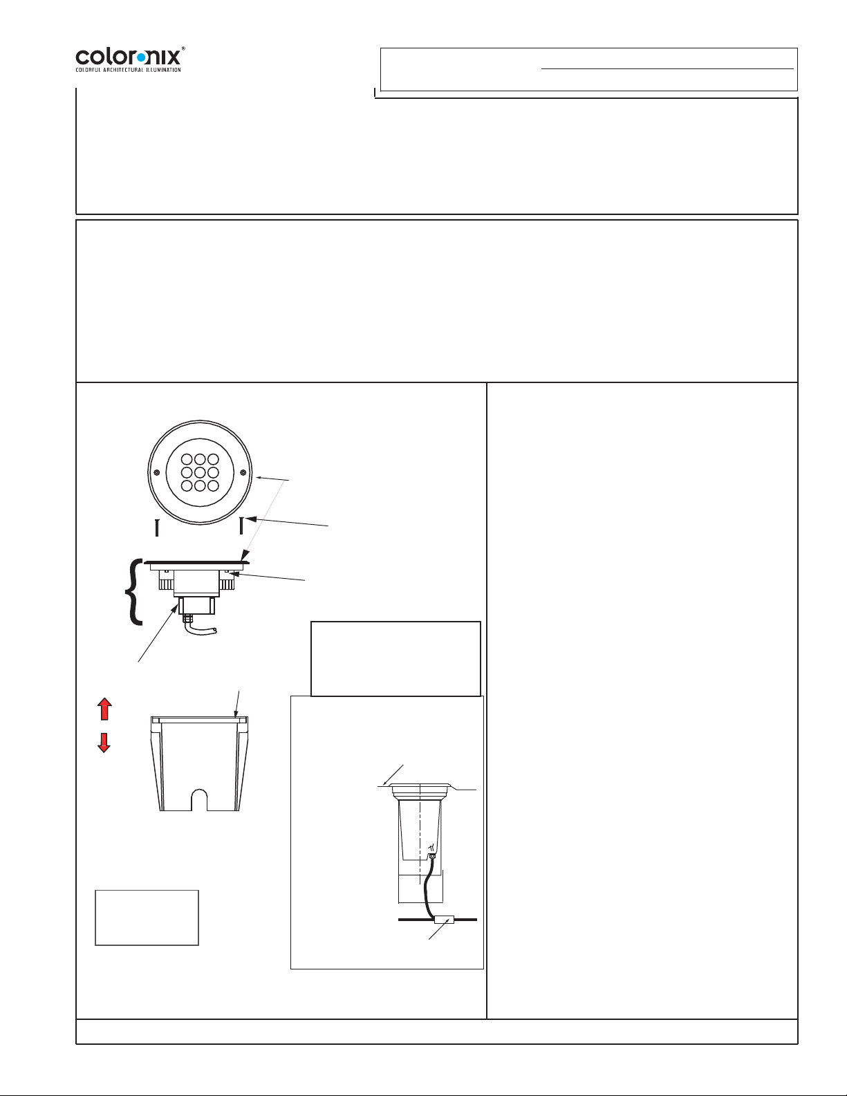
Stainless Steel faceplate. with
housing and cord
(2) Block out mounting screws
(flat head cap screws,
M5 x 25mm long) M3 hex key.
Hsg
Assy.
(fixture)
housing
with LED
driver and
cord.
Tools:
M3 hex key/wrench
M4 hex key/wrench
(by others)
Block Out Housing
(4) socket head screws
(M5 x 10mm long) M4 hex key.
To remove faceplate from housing.
- Drive over and walk over ratingsStatic load: 5500 LBS maximum
(walk over). Vehicle dynamic load:
55000 Lbs maximum at less than 6
mph (pneumatic tires).
Typical installation. Your installation may differ. See wiring
instructions for more information.
FIG. 1
Grade level.
Grade level.
Shown:
Cord in
underground
junction box (by
others).
Bottom of
Stainless steel
Faceplate at
grade level.
Underground junction box
(by others)
complete your installation (see FIG 1 below). Test for drainage by
Fixture Installation:
NOTE: READ AND FOLLOW ALL INSTALLATION
INSTRUCTIONS BEFORE INSTALLING FIXTURE.
1. Make sure supply wiring is in place before installing
fixture and before completing graded surface and
there is enough wiring to extend outside of the hole
for installing fixture.
2. Remove Block-Out mounting screws from the
stainless steel faceplate and remove Block-Out
Housing from fixture.
3. Place Block-Out Housing (with fixture) in the
ground so that the bottom of the stainless steel
faceplate is at finish grade level.
4. Check to see that hole is at least deep enough for
fixture and underground junction box (by others) (see
FIG. 1), as needed/required.
5. Wire fixture to data enabler.
Red/Black +24DC to V+
Blue/Black -24DC to V-
Green/Black (White) to WBlue (Blue) to BGreen (Green) to GRed (Red) to R-
6. Secure connection using UL Listed wire
nuts/connectors and then with UL Listed Electrical
tape (by others), as required, appropriate for the
connection. If connections are underground an
underground junction box (by others) may be needed
(see FIG.1).
7. Place Fixture in hole and then mount sealed fixture
(with LED’s) to Block-Out housing and secure with
Block-Out mounting screws.
“In-Grade” LUMINAIRE
(Typical installation. Your installation may differ)
© Copyright 2015. Specifications subject to change without notice.
 Loading...