

Page 1

C.B250A-BTC V20
User’s Manual
Motherboard
Colorful Technology Website:
http://www.colorful.cn
Page 2

Copyright
This motherboard manual belongs to Colorful Technology and Development
CO, LTD. No one is permitted to copy, change, or translate without our
written permission.
Disclaimer
The products name we mentioned in this manual is only for identifying, all
of the brands belong to other company.
The registered trademarks of IBM, VGA and PS/2 belong to International
Business Machines.
The registered trademarks of Intel, Pentium, Pentium Ⅱ, Celeron, Pentium
III and Pentium 4 belong to Intel.
The registered trademark of Athlon belongs to Advanced Micro Devices,
Inc.
The registered trademarks of Microsoft, MS-DOS, Windows 95/98/NT,
Windows2000/XP etc. belong to Microsoft.
All of the trademarks in this manual have been registered.
Page 3

3
1. Introduction
Thanks for purchasing our based on Intel B250 Chipset motherboard. The
motherboard C.B250A-BTC V20 based on Intel B250 Express Chipset,
support Intel LGA1151 CPUs, support dual channel DDR4 2400/2133MHZ
memory, support PCI-E 3.0 standard。
The motherboard provides 1*HDMI port、1*VGA port、1*DVI port、
2*DDR4 memory slots、5*SATA3.0、6*USB2.0、6*USB3.0 ports(including
headers)、onboard 6-CH audio chipset、onboard 1000M LAN chipset,it’s a
Cost-effective motherboard!
The motherboard provides 1*PCI Express x16 slot、5*PCI Express x1 slots、
6*UPCIE slots,extension pattern is diversity and extension performance is
strong.
1.1. Packing Contents
1*Colorful Battle Flag C.X370 X5 V14 motherboard
2*SATA cables
1*Driver/Utility CD
1*User's Guide
1*I/O shield
Page 4
4
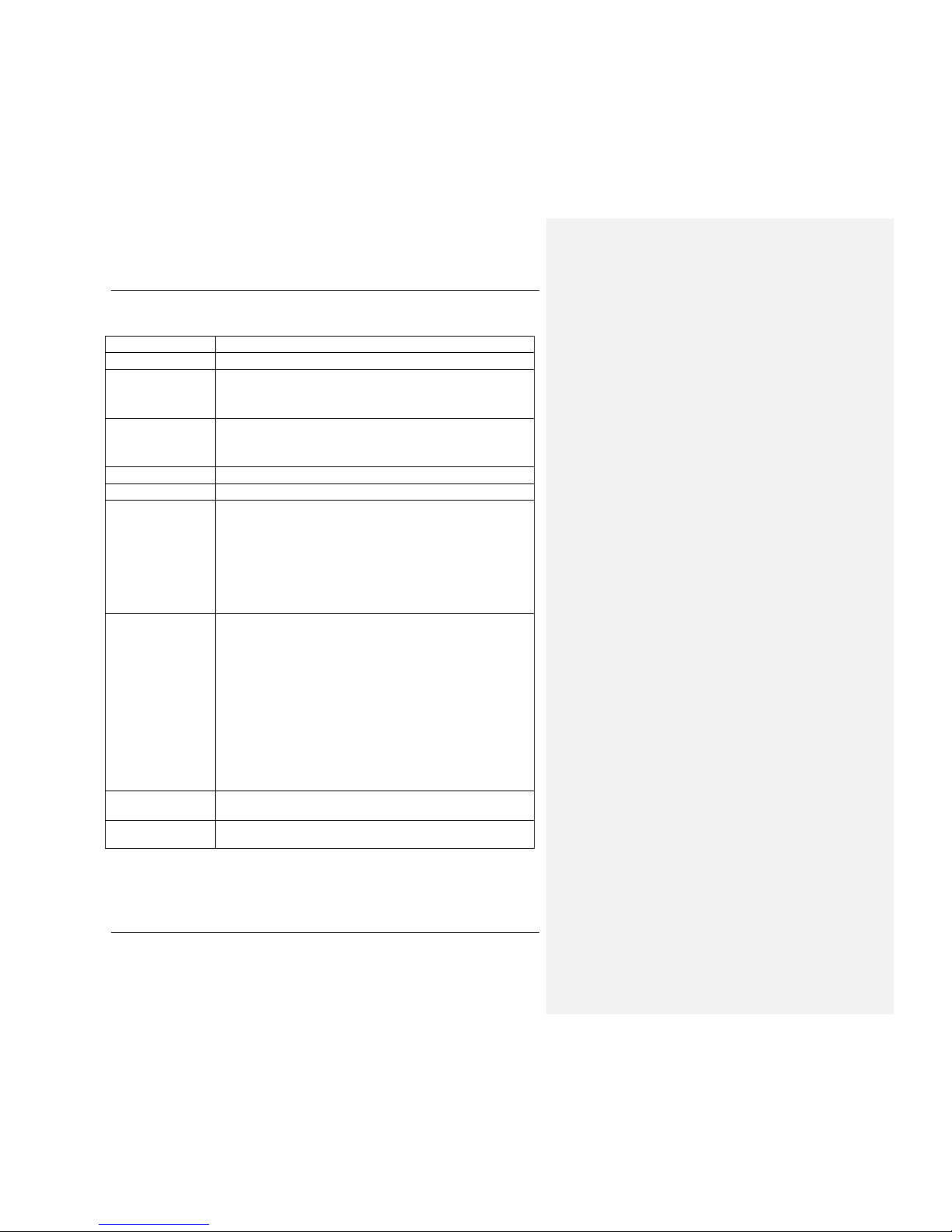
1.2. MOTHERBOARD SPEC
CPU
Support
Intel LGA1151
CPUS
Chipset
Intel B250
Main Memory Dual-Channel DDR4 2400/2133MHZMHz
support
Offer 2 DIMM
slots
Slots 1*PCI Express 3.0x16 slot
5*PCI Express x1 slots
6
*UPCIE slot
s
Storage
5
*SATA3.0 6Gb/s ports
USB
6*USB2.0
+6*
USB3.0
Rear IO
Connector
1*PS/2 Mouse/ Keyboard port
1*LAN(RJ45) port
2*USB 2.0 ports
2*USB 3.0 ports
6-Channel Audio I/O
1*VGA+DVI Port
1*HDMI Port
Other
Connectors
2*USB2.0 headers((F_USB20_1,FUSB20_/2/3)
1*9-pin Front panel audio connector(F_AUDIO)
1*System panel connector(F_PANEL)
1*USB3.0 header(USB3F)
3*FANs(1*CPU_FAN,2*SYS_FAN)
1*PC speaker connector(SPEAK)
1*debug header(JLPC)
1*COM header(JCOM1)
1*JSPD_OUT header(JSPD_OUT)
1*ME header(ME)
2*4-pin Power connector
(
12V_AUX1,12V_AUX4
)
High Definition
Audio
6-channel High Definition Audio Codec integrated
HD audio
Onboard LAN
Onboard 1000M LAN
Provides 10/100/1000Mb Et
hernet
Page 5
5
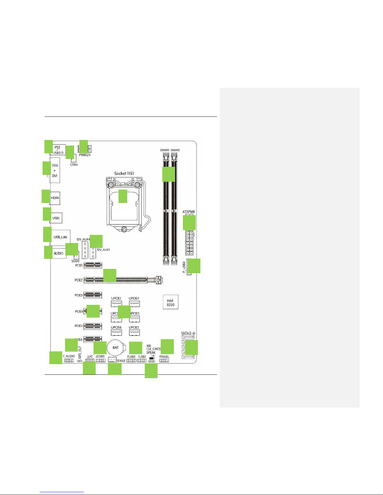
1.3.
Motherboard Layout
1
2
3
4
5
6
7
8
9
10
11
12
13
14
15
16
17
18
19
20
21
17
22
23
24
25
Page 6

6
1.PS/2 Mouse/ Keyboard port and USB2.0 ports
2.Connect to VGA+DVI monitor
3.Connect to HDMI monitor
4.Connect to USB3.0 devices
5.Connect to USB3.0 devices and LAN
6.Audio devices
7.8-pin ATX 12V Power connector
8.CPU Fan connector
9.Intel LGA1151 socket
10.DIMM slots
11.24-pin ATX Power connector
12.USB 3.0 header
13.SATA3.0 port
14.System panel connector
15.ME header/Clear CMOS jumper/Speaker connector
16.USB 1.1/2.0 header
17.System FAN connector
18.COM header
19.JLPC header
20.JSPD_OUT header
21.Front panel audio connector
22.PCI Express x1 slot
23.UPCIE slot
24.PCI Express 3.0 x16 slot,for VGA Card
25.4-pin Power connector(auxiliary power supply)
Page 7

7
2. Hardware Installation
This section will guide you through the installation of the motherboard. The
topics covered in this section are:
Preparing the motherboard
Installing the CPU
Installing the CPU fan
Installing the memory
Installing the motherboard
Connecting cables and setting switches
2.1. Safety Instructions
To reduce the risk of fire, electric shock, and injury, always follow basic
safety precautions.
Remember to remove power from your computer by disconnecting the AC
main source before removing or installing any equipment from/to the
computer chassis.
2.2. Preparing the Motherboard
The motherboard shipped in the box does not contain a CPU or memory.
You need to purchase a CPU, a CPU fan assembly, and memory to complete
this installation.
2.2.1. Installing the CPU
Be very careful when handling the CPU. Make sure not to bend or break any
pins on the back. Hold the processor only by the edges and do not touch the
bottom of the processor.
Use the following procedure to install the CPU onto the motherboard.
1. Unhook the socket lever by pushing down and away from the socket.
2. Lift the load plate. There is a protective socket cover on the load plate to
protect the socket when there is no CPU installed.
3. Remove the protective socket cover from the load plate.
4. Remove the processor from its protective cover, making sure you hold it
only by the edges.
It is a good idea to save the cover so that whenever you remove the CPU,
you have a safe place to store it.
5. Align the notches in the processor with the notches on the socket.
6. Lower the processor straight down into the socket with out tilting or
sliding it into the socket
Make sure the CPU is fully seated and level in the socket.
Page 8

8
7. Close the load plate over the CPU and press down while you close and
engage the socket lever.
8. There are many different fan types that can be used with this
motherboard. Follow the instruction that came with you fan assembly.
Be sure that the fan orientation is correct for your chassis type and your
fan assembly.
The CPU fits in only one correct orientation. DO NOT force the CPU into
the socket to prevent bending the connectors on the socket and damaging
the CPU!
Page 9

9
2.3. Installing Memory DIMMs
Your new motherboard has 2 slots for DDR4 memory. They support dual
channel DDR4 memory technology. There must be at least one memory
bank populated to ensure normal operation. Use the following the
recommendations for installing memory.
1 DIMM: Install into DIMM1. You can install the DIMM into any slot,
however, slot 1 is preferred.
2DIMMs:Install into DIMM1&DIMM2 slots or DIMM-2&DIMM-4
slots, to build dual channel。
Use the following procedure to install memory DIMMs into the slots on the
motherboard. Note that there is only one gap near the center of the DIMM
slot. This slot matches the slot on the memory DIMM to ensure the
component is installed properly.
Unlock a DIMM slot by pressing the module clips outward.
Align the memory module to the DIMM slot, and insert the module
vertically into the DIMM slot. The plastic clips at both sides of the
DIMM slot automatically lock the DIMM into the connector.
2.4. Installing the Motherboard
The sequence of installing the motherboard into the chassis depends on the
chassis you are using and if you are replacing an existing motherboard or
working with an empty chassis. Determine if it would be easier to make all
the connections prior to this step or to secure the motherboard and then
make all the connections. Use the following procedure to install the I/O
Page 10

10
shield and secure the motherboard into the chassis.
Be sure that the CPU fan assembly has enough clearance for the chassis
covers to lock into place and for the expansion cards. Also make sure the
CPU Fan assembly is aligned with the vents on the covers.
2.5. Installing the I/O Shield
The motherboard kit comes with an I/O shield that is used to block radio
frequency transmissions, protects internal components from dust and foreign
objects, and promotes correct airflow within the chassis.
Before installing the motherboard, install the I/O shield from the inside of
the chassis. Press the I/O shield into place and make sure it fits securely. If
the I/O shield does not fit into the chassis, you would need to obtain the
proper size from the chassis supplier.
2.6. Securing the Motherboard into the Chassis
Most computer chassis have a base with mounting studs or spacers to allow
the mother board to be secured to the chassis and help to prevent short
circuits. If there are studs that do not align with a mounting hole on the
motherboard, it is recommended that you remove that stud to prevent the
possibility of a short circuit.
1. Carefully place the motherboard onto the studs/spacers located inside
the chassis.
2. Align the mounting holes with the studs/spacers.
3. Align the connectors to the I/O shield.
4. Ensure that the fan assembly is aligned with the chassis vents according
to the fan assembly instruction.
5. Secure the motherboard with a minimum of eight-to-ten screws.
2.7. Connecting Cables and Setting Switches
This section takes you through all the connections and switch settings
necessary on the motherboard. This will include:
Power Connections
24-pin ATX power
Page 11

11
8-pin ATX 12V power
Internal Headers
Front panel
USB Headers
Audio
Serial ATA III
Chassis Fans
Rear panel USB 2.0 Adapter
Expansion slots
2.7.1. ATX power connectors (24-pin ATXPWR, 8-pin ATX12V)
These connectors are for an ATX power supply. The plugs from the power
supply are designed to fit these connectors in only one orientation. Find the
proper orientation and push down firmly until the connectors completely fit.
2.7.2. Serial ATA 3.0/6.0 Gb/s connectors (7-pin)
These connectors connect to Serial ATA 3.0/6.0 Gb/s hard disk drives and
optical drives via Serial ATA 3.0/6.0 Gb/s signal cables.
Page 12

12
2.7.3. Back Panel IO Connector
Parts Use
PS/2 Mouse
Connector
This connector is for a PS/2 mouse.
PS/2 Keyboard
Connector
This connector is for a PS/2 keyboard.
LAN Jack
The standard RJ
-
45 jack is for connection to single
Local Area Network (LAN). You can connect a
network cable to it.
Lie-In(Blue)
Used for external CD player, tape player or other
audio devices.
Line Out(Green)
This connector for speakers or headphones.
Side R/L(Gray)
Side surround speakers connector
VGA Onboard VGA
, connect to Monitor
DVI
Onboard
DVI port
, connect to D
V
I Monitor
Page 13

13
HDMI
Onboard HDMI port, connect to HDMI Monitor
USB Ports
These connectors are for attaching USB devices
such as keyboard, mouse, or other USB-compatible
devices.
2.7.4. USB 3.0 connectors
This connector is for USB 3.0 devices.
2.7.5. USB2.0 connectors
These connectors are for USB 2.0 ports. Connect the USB module cable to
any of these connectors, then install the module to a slot opening at the back
of the system chassis. These USB connectors comply with the USB 2.0
specification that supports up to 480Mbps connection speed.
Page 14

14
2.7.6. F_AUDIO(Front panel audio connector)
This connector is for a chassis-mounted front panel audio I/O module that
supports either High Definition Audio or AC`97 audio standard. Connect
one end of the front panel audio I/O module cable to this connector.
2.7.7. System panel connector
This connector supports several chassis-mounted functions.
Page 15

15
System power LED (2-pin PLED)
This 2-pin connector is for the system power LED. Connect the chassis
power LED cable to this connector. The system power LED lights up when
you turn on the system power, and blinks when the system is in sleep mode.
Hard disk drive activity LED (2-pin IDE_LED)
This 2-pin connector is for the HDD Activity LED. Connect the HDD
Activity LED cable to this connector. The IDE LED lights up or flashes
when data is read from or written to the HDD.
System warning speaker (4-pin SPEAKER)
This 4-pin connector is for the chassis-mounted system warning speaker. The
speaker allows you to hear system beeps and warnings.
ATX power button/soft-off button (2-pin PWRSW)
This 2-pin connector is for the system power button.
Reset button (2-pin RESET)
This 2-pin connector is for the chassis-mounted reset button for system
reboot without turning off the system power.
2.7.8. CPU, Chassis, and Power fan connectors (4-pin CPU_FAN,
3-pin PWR_FAN)
Connect the fan cables to the fan connectors on the motherboard, making
sure that the black wire of each cable matches the ground pin of the
connector.
Page 16

16
2.7.9. SPDIF header
:
JSPD_OUT
This SPDIF header is for SPDIF audio devices
2.7.10. Debug header:JLPC
This Debug header is for Debug serial devices
Page 17

17
2.7.11. COM header
:
JCOM1
This COM header is for COM serial devices
2.7.12. Clear CMOS Jumper: CLR_CMOS
There is a CMOS RAM on board that has a power supply from external
battery to keep the system configuration data. With the CMOS RAM, the
system can automatically boot OS every time it is turned on. If you want to
clear the system configuration, use the CLR_CMOS Jumper to clear data.
Clear CMOS PROCEDURE
Page 18

18
You can clear CMOS by shorting 1-2 pin. Before you clearing the CMOS,
following next procedure:
1. Turn off the AC power supply and connect pins 1 and 2 together using
the jumper cap.
2. Return the jumper setting to normal (pin 2 and 3) or Remove the jumper
cap
3. Turn the AC power supply back on.
2.7.13. PCI Express x16 Slots
The PCI Express x16 slot is reserved for a graphics or video card. The
bandwidth of the x16 slot is up to 8GB/sec.
When installing a PCI Express x16 card, be sure the retention clip snaps and
locks the card into place. If the card is not seated properly, it could cause a
short across the pins. Secure the card’s metal bracket to the chassis back
panel with the screw used to hold the blank cover.
Clear CMOS settings
2-3 clear CMOS
CLR_CMOS CLR_CMOS
1-2 normal
Page 19

19
Copyright Notice
The material in this document is the intellectual property of Colorful
Technology and Development CO, LTD. We take every care in the
preparation of this document, but no guarantee is given as to the correctness
of its contents. Our products are under continual improvement and we
reserve the right to make changes without notice.
Trademarks
All trademarks in this manual are properties of their respective owners.
■■ NVIDIA® is registered trademark of NVIDIA Corporation.
■■ AMD® is registered trademarks of AMD Corporation.
■■ Intel® is registered trademarks of Intel Corporation.
PCI Express x1
PCI Express x16
PCI Express x16 PCI Express x16
PCI Express x1
PCI Express x1
PCI Express x1
PCI Express x1
Formatiert: (Asiatisch) Chinesisch (VR China)
Formatiert: (Asiatisch) Chinesisch (VR China)
Formatiert: (Asiatisch) Chinesisch (VR China)
Formatiert: (Asiatisch) Chinesisch (VR China)
Formatiert: (Asiatisch) Chinesisch (VR China)
Formatiert: (Asiatisch) Chinesisch (VR China)
Formatiert: (Asiatisch) Chinesisch (VR China)
Formatiert: (Asiatisch) Chinesisch (VR China)
Page 20

20
■■ Windows® is registered trademarks of Microsoft Corporation.
■■ AMI® is registered trademark of American Megatrends Inc.
■■ Award® is a registered trademark of Phoenix Technologies Ltd.
■■ Realtek® is registered trademark of Realtek Semiconductor Corporation.
■■ JMicron® is registered trademark of JMicron Technology Corporation.
■■ ASMedia® is registered trademark of ASMedia Technology Inc.
Technical Support
If a problem arises with your system and no solution can be obtained
from the user’s manual, please contact your place of purchase or local
distributor. Or our engineer, send the follow information to us!
Customer name___ Purchase date___
Contacts_________ Contact phone___
Contact address___ Product model___
Product SN ___ Dealer name___
Dealer phone ___ Dealer address ___
Website: www.colorful.cn
Service hotline:
+86400-678-5866
Entering BIOS Setup
Power on the computer and the system will start the Power On
Self Test (POST)process. When the message below appears on
the screen, press <DEL> key to enter BIOS:
Press DEL to Run Setup,Press F2 to Load default values and continue
Boot Option Priorities(how to install operating system)
Boot device Priority Setting。If user will
install operating
system
, please put“Boot Option #1”set to your CD-ROM or your
USB device, After setting, press "F10" key to save and exit,,
System boot from CD-ROM or U disk。
Page 21

21
Main
Advanced
Chipset
Boot Security
C.Oclock
→←Select Screen
Up/Down:Choose Item
Enter/ Click: Select
+/-: Change Opt
F1: General Help
F7: Previous Values
F9: Optimized
Defaluts
F10: Save&Exit
ESC/Right Click:
Exit
Boot Configuration
Setup Prompt Timeout
Bootup Numlock State
Full LOGO Display
Boot Option Priorities
Boot Option #1
Boot Option #2
Hard Drive BBS Priorities
1
On
Enabled
 Loading...