

Page 1
CoCo SDC
Page 2

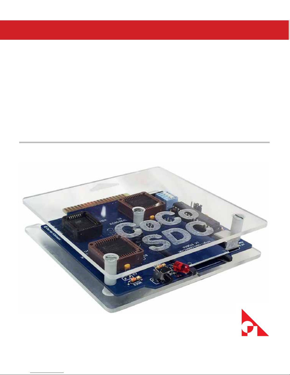
About the cover image:
Darren Atkinson designed the CoCo SDC hardware and soware.
http://cocosdc.blogspot.com
Printed circuit board manufactured by Ed Snider.
https://sites.google.com/site/thezippsterzone/
e clear acrylic case designed by Tim Lindner.
https://youtu.be/OdSOUcd60Ok
is manual takes inspiration from Brian Blake’s original.
Page 3

COCO SDC | iii
Table of Contents
1. What is the CoCo SDC? ................................................................................... 1
Features and Specications ...........................................................................................2
Hardware Guide ................................................................................................................. 2
Jumper Settings ................................................................................................................. 3
DIP Switch Settings ........................................................................................................... 3
How is the SDC dierent from competing products? .......................................... 4
2. Getting Ready For Fun ................................................................................... 5
The Basics ............................................................................................................................. 5
D & E Compatibility Issues .............................................................................................. 5
Identifying the problem boards ................................................................................... 6
Motherboard Modication ............................................................................................. 6
Finding a Suitable Enclosure ......................................................................................... 7
Updating SDC-DOS ........................................................................................................... 7
Rescuing After a Failed Update ..................................................................................... 8
Recovery Steps.................................................................................................................... 9
3. Using the SDC ............................................................................................... 11
DRIVE – Mounting SD Based Images ........................................................................12
Multiple Disks .................................................................................................................... 12
DRIVE – With Wildcards .................................................................................................. 13
DIR .........................................................................................................................................14
Setting Current Directory..............................................................................................15
Explaining DIR ................................................................................................................... 15
Locking Disk Images ....................................................................................................... 16
Creating New Disk Images............................................................................................16
Ejecting a Disk Image ..................................................................................................... 16
Page 4

iv | Table of Contents
Using the CoCo SDC with Drivewire .........................................................................16
Connecting via the Color Computer .........................................................................17
Accessing Real Floppy Disks ........................................................................................18
Automatic Program Execution .................................................................................... 18
EXP ........................................................................................................................................19
DEF DW = n ........................................................................................................................19
4. Using the Flash ............................................................................................. 21
Running a Cartridge Image .......................................................................................... 21
Erasing Banks and Sectors ............................................................................................ 22
Writing to the Flash .........................................................................................................22
Copying a Block of Memory ......................................................................................... 23
5. About File Formats ....................................................................................... 25
DSK Images ........................................................................................................................25
Disk Geometry Table for DSK Images .......................................................................26
JVC Images .........................................................................................................................26
VDK Images ........................................................................................................................ 26
SDF Images ........................................................................................................................27
SDF File Format ................................................................................................................. 28
Contents of the SDF 512 byte File Header .............................................................. 28
Contents of the SDF 256 byte Track Header ...........................................................29
Page 5

COCO SDC | 1
1
What is the CoCo SDC?
e CoCo SDC is a home-brew project for the
TRS-80 Color Computer (CoCo). It has been in
various stages of development since 2009. e
original plan was to provide oppy controller
emulation which worked in conjunction with
the Drivewire server. at idea was eventually
scrapped in favor of a self-contained system
using an SD card.
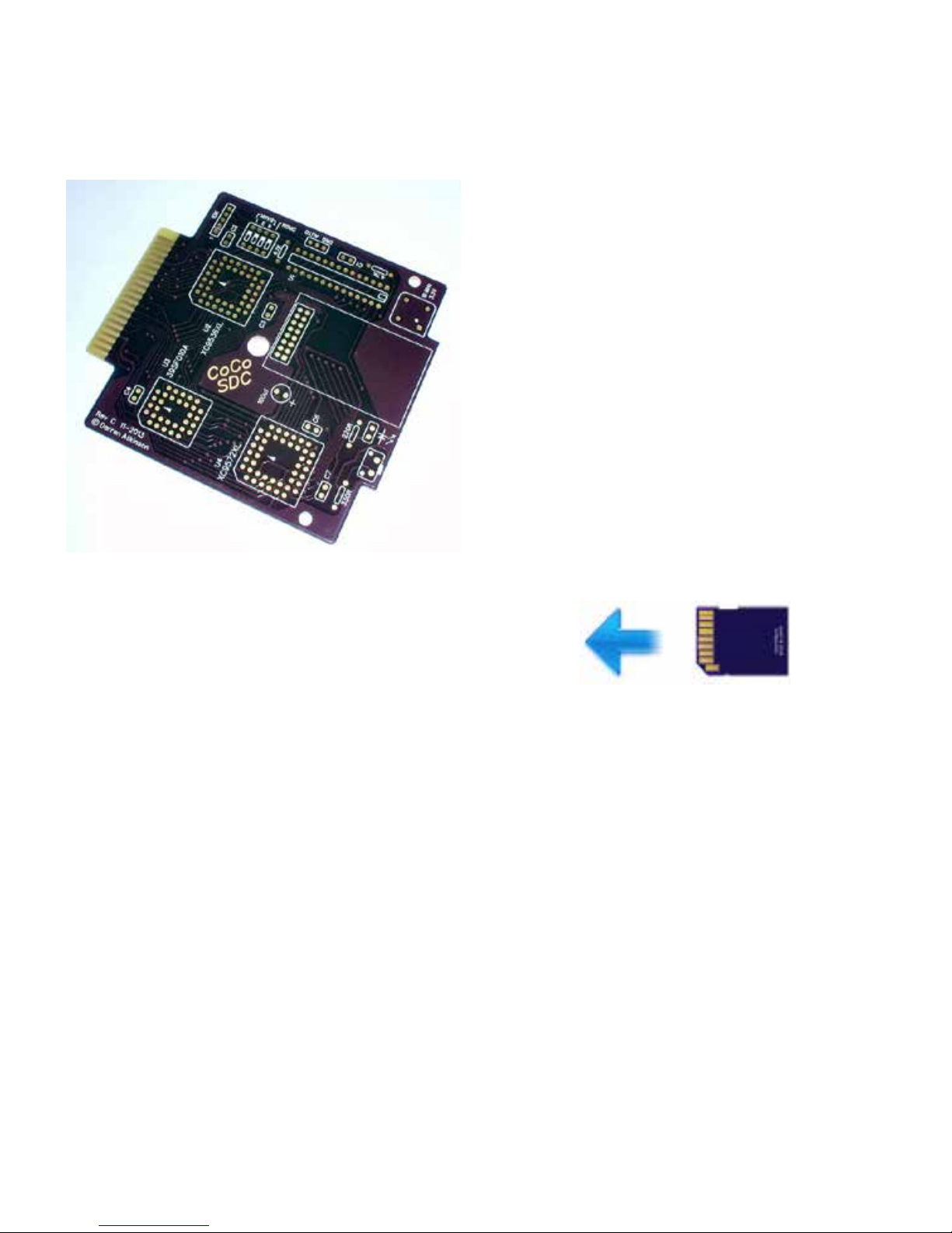
CoCo SDC Prototyping.
A number of high capacity storage solutions
have previously been developed for the CoCo,
including a MicroSD card interface, a handful
of IDE and SCSI interfaces and the very
popular Drivewire server.
One drawback of these oerings has been
that they aren’t compatible with soware that
was written to interact directly with a oppy
disk controller. is isn’t so much a problem if
you are primarily using the CoCo for BASIC
programming or running OS9 soware.
ere are however a number of titles (mostly
commercial games) that fail to work with those
other systems.
e CoCo SDC aims to solve the compatibility
problem by combining the traditional “soware
hook” approach with a robust emulation of
the oppy controller in hardware. is dual
mode implementation provides excellent
performance for the majority of soware which
“plays by the rules” while adding a high degree
of compatibility with those titles that employ
oppy-based copy protection schemes or
simply choose to roll their own oppy drivers.
An enhanced LBA access mode has also been
incorporated into the rmware, allowing the
CoCo SDC to go beyond simply emulating
oppy disks and interface with virtual hard disk
images as large as 2 gigabytes. Two separate
disk images (oppy or hard disk) contained
on the same SD card may be “connected”
simultaneously.
Page 6
2 | Chapter 1
CoCo SDC Revision 3 Board.
Also on board is 128K of Flash memory
which is divided into 8 banks of 16K. ese
16K banks are both hardware and soware
selectable and occupy the cartridge ROM space
from $C000 to $FEFF.
One bank of the Flash memory is used to
hold the SDC-DOS code which is yet another
patched version of Microso’s Disk Extended
Color BASIC 1.1. Included in SDC-DOS are
additional commands to mount disk image les
on the SD card, program the Flash and execute
ROM images contained in the Flash. Drivewire
disk support is also included in SDC-DOS.
Features and Specications
• Atmega 328P AVR micro controller @ 10Mhz
• Custom 512 byte boot-loader allows rmware
to be updated by the CoCo
• 128K In-System-Programmable Flash
• Accepts SD/SDHC cards formatted with
FAT16 or FAT32 le system
• Emulates a Tandy Floppy Disk Controller
• Emulate Dragon DOS oppy controllers
• LBA access mode for virtual hard disk
support
• Extensions to Disk BASIC in SDC-DOS for
disk image manipulation
• Drivewire disk protocol with auto-speed
conguration for CoCo 1, 2 or 3
• “Disk Switch” button to support multi-disk
programs
• PCB can be mounted in a Tandy FD-502
enclosure
Hardware Guide
SD Card Direction.
e SD card socket is a Push-Push type. When
removing the card, always push in to release
the latching mechanism before sliding the
card out. Never use force to pull the card out
of the socket. e card must be inserted into
the socket upside-down (label facing down,
contacts facing up). Use only SD or SDHC
cards with the CoCo SDC.
Page 7
COCO SDC | 3
Insert the card into the socket before applying
power to the CoCo or Mult-Pak Interface.
When power is applied, the LED on the CoCo
SDC board should light up momentarily. If
the LED does not turn o aer a few seconds
then this is an indication that the card was not
recognized by the hardware. is can happen if
the card has not been formatted with a FAT16
or FAT32 le system. It could also indicate that
the card was not inserted properly or that there
is a problem with the CoCo SDC itself.
Although SD cards are hot-swappable, the
CoCo SDC rmware does not handle that
situation very well. It’s recommended that
you completely shutdown the CoCo and
MPI before swapping cards.
Jumper Settings
e three-pin jumper strip provides two
mutually exclusive options for board
conguration; Cartridge Auto-Start and
Dragon DRQ Mode. e default setting has
neither option enabled (no jumper installed).
Installing a jumper between the center pin
and the AUTO pin connects the Q clock to the
CART interrupt pin. is causes the computer
to automatically start executing the program in
the selected Flash bank at power-up. Do NOT
use this option to auto-start SDC-DOS or other
Disk BASIC ROMs.
Installing a jumper between the center pin and
the DRQ pin is required to support emulation
of a Dragon DOS oppy controller. Do NOT
install a jumper in this position when using the
board with a CoCo.
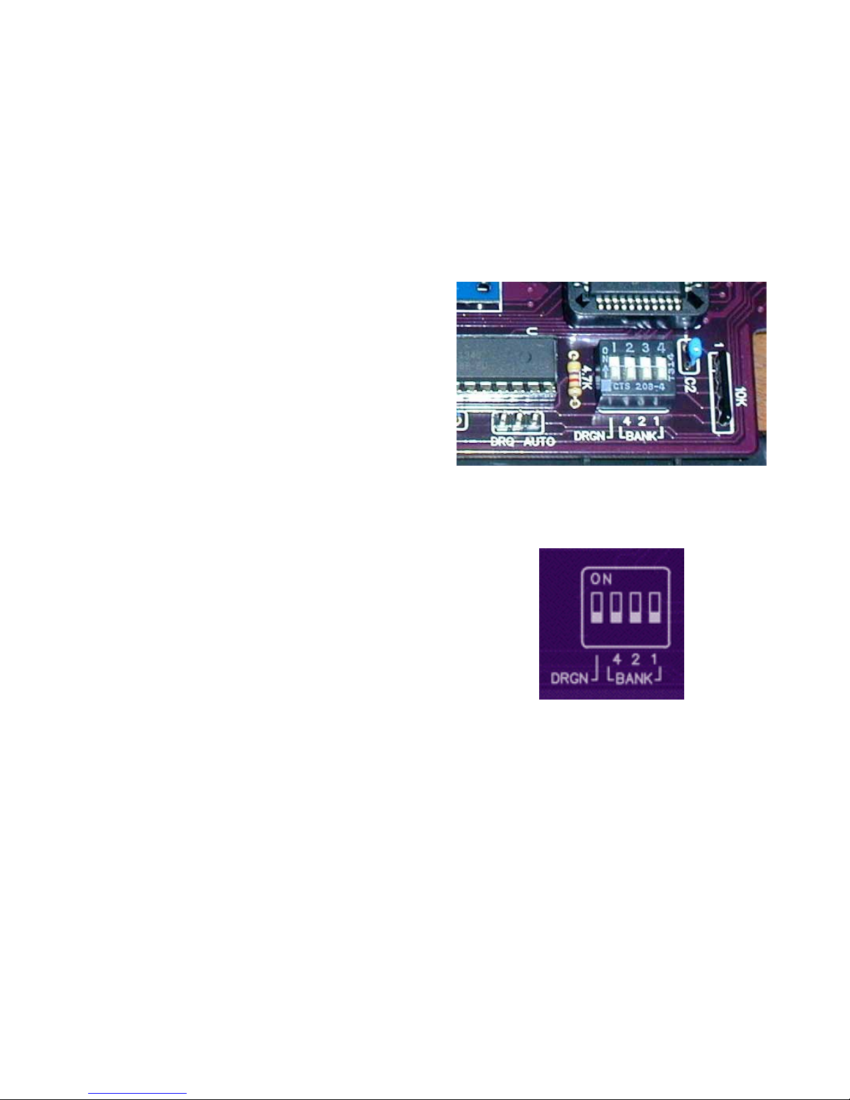
Jumper & DIP Switches.
DIP Switch Settings
e board includes a 4-position DIP switch
that is used to congure which bank of Flash
is active at power-up or reset and which
addressing scheme is used to communicate
with the controller.
CAUTION: Make sure the computer’s power
is o before making any changes to the DIP
switch settings!
Page 8
4 | Chapter 1
ree of the switches specify the Flash bank to
activate upon power-up or system reset. e
switches are labeled on the board as 4, 2 and
1. e eight Flash banks are numbered 0 to 7.
Place only those switches whose sum equals the
desired bank number into the ON position. For
example, to select bank 5, place the switches
labeled 4 and 1 into the ON position and leave
the switch labeled 2 in the OFF position. e
board is provided with SDC-DOS in bank 0
of the Flash and all three switches in the OFF
position.
e DRGN switch selects the address scheme
for the controller. In the OFF position the
controller will use the CoCo address scheme.
In the ON position, the controller will use the
Dragon DOS address scheme. e dierent
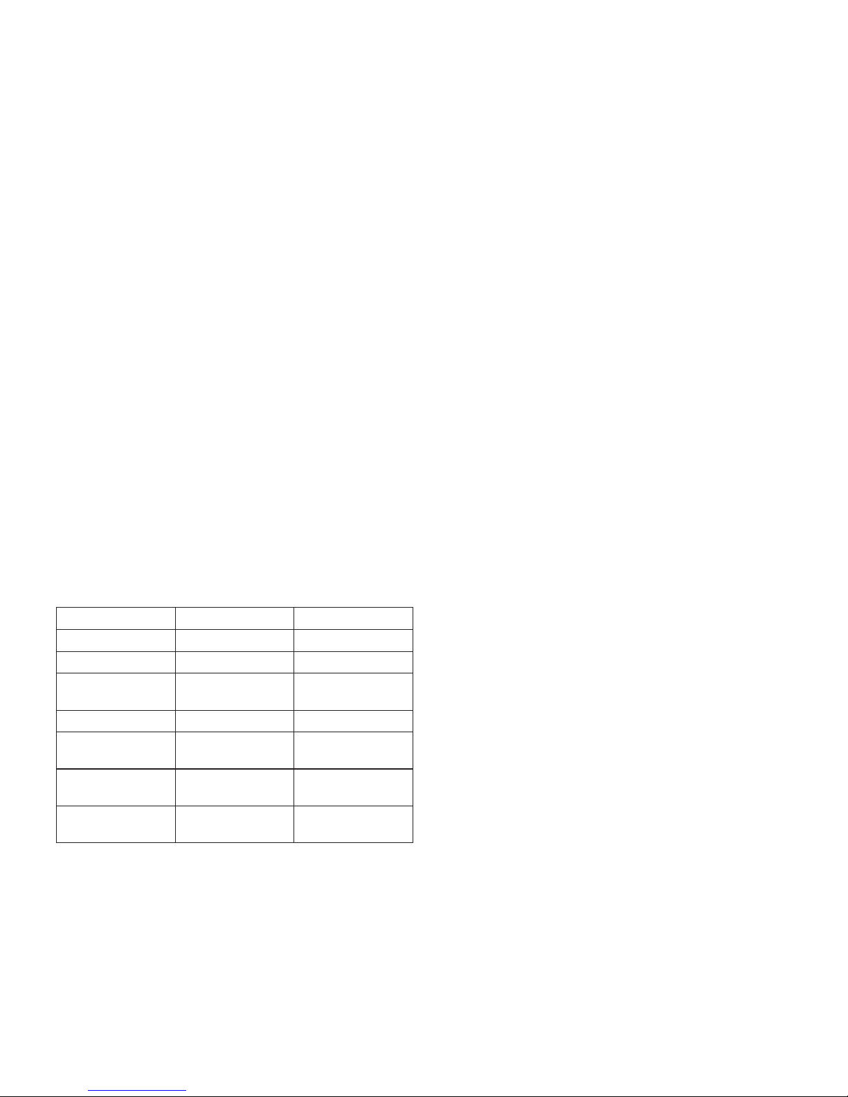
schemes are summarized in the following table.
Usage CoCo Address Dragon Address
Drive Control Latch FF40 FF48
Flash Data Register FF42 FF4A
Flash Control
Register
FF43 FF4B
Command/Status FF48 FF40
FDC Track Register
I/O Register 1
FF49 FF41
FDC Sector Register
I/O Register 2
FF4A FF42
FDC Data Register
I/O Register 3
FF4B FF43
CoCo & Dragon Address Schemes.
How is the SDC dierent from competing
products?
• No reliance on expensive third-party
modules like the 4D systems uDrive.
• Does not use a slow serial interface based on
an obsolete part (6551 ACIA).
• True emulation of the oppy controller
hardware for maximum compatibility.
• Supports the popular Drivewire protocol for
PC-based disk images.
• Eight banks of in-system-programmable
Flash instead of an EPROM.
• Ability to “switch disks” for multi-disk
programs via a button on the controller.
• SD cards are FAT-formatted and require no
special imaging utility for a PC/Mac.
Probably the only drawback of the device is
the fact that the SDC does not come with an
enclosure.
John Strong has been known to make 3D
printed cases available. Here is his website:
http://strongware.net/author/johnstrong/
Page 9

COCO SDC | 5
2
Getting Ready For Fun
The Basics
ere are a few very important things that must
be touched upon before we get into the actual
operation of the CoCo SDC:
1. NEVER insert or remove the CoCo SDC
into a CoCo that is turned on! Just like any
other device that uses a Color Computer
cartridge port, inserting the CoCo SDC into
your Color Computer can damage the Color
Computer, CoCo SDC, or both.
2. Although SD cards are hot-swappable, the
CoCo SDC rmware does not handle that
situation very well. It’s recommended that
you completely shutdown the CoCo and
MPI before swapping cards.
3. e rmware in the CoCo SDC does
not currently support long le names. You
must ensure that the names of all les and
directories which are to be accessible by
the CoCo conform to the older 8.3 naming
conventions.
D & E Compatibility Issues
e CoCo SDC is compatible with all versions
of the Color Computer and Dragon Computer
lines. However, aer getting the CoCo SDC
into the hands of some users, it was discovered
that Flash programming does not work
correctly on certain CoCo 1 motherboards. e
two earliest CoCo 1 boards known as the ‘D’
and ‘E’ boards are the culprits.
Board Identiers.
Page 10

6 | Chapter 2
e Cartridge Select Signal (CTS) on these
boards exhibits too slow of a rise-time which
causes problems for the high-speed Flash chip.
is does not aect normal operation of the
CoCo SDC in terms of being able to read data
or execute code from the Flash. When writing
to the Flash however, the slow rise time oen
results in incorrect data being stored in the
chip.
ere are a few options to deal with this
problem:
1. Do not use a CoCo 1 with one of the
aforementioned motherboards to program
the Flash. is option is not ideal, especially if
you don’t have another suitable CoCo in your
possession.
2. Use a Multi-Pak Interface when
programming the Flash. e signal buering
in the MPI acts as a kind of lter for the CTS
line, producing a nice clean transition. is is a
good option if you do not wish to modify your
CoCo and you happen to own an MPI.
3. Perform a simple modication to the CoCo
1 motherboard to x the problem (see details
below).
Identifying the problem boards
To determine if your CoCo 1 has one of the
problematic motherboards you will need to
open the case and look inside. e boards in
question have a large metal shielded area that
encloses all of the main logic chips including
the RAM, CPU, SAM, VDG and PIAs. ere
should be a number printed on the board just
below the cartridge port which ends with “-D”
or “-E” as seen in the photos below.
If your board has a smaller RF shield which
only covers the SAM and RAM chips, or has a
number printed on the board (near the frontle corner) that ends in ‘285’ then this is what
is oen referred to as the ‘F’ board. e ‘F’
board does not exhibit the problem and needs
no modication.
Motherboard Modication
Please note that any modication to the CoCo
is performed at your own risk. Although it
is highly unlikely that this modication will
cause any problems with other hardware, I can’t
be held responsible for any damage or loss of
functionality that may occur should you choose
to go through with it.
Page 11
COCO SDC | 7
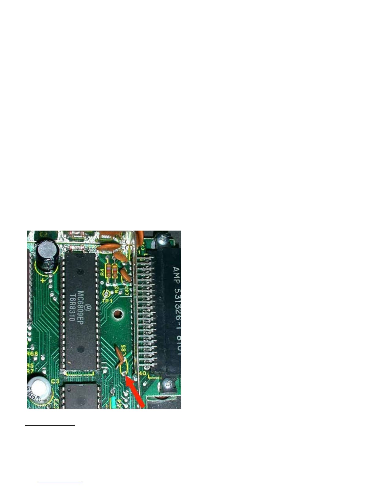
e modication is rather simple and involves
cutting just one leg of a capacitor. Be sure to
disconnect power to the CoCo and discharge
any static electricity from your body before
touching any of the components inside the
CoCo. e aected capacitor is located within
the shielded area so you will need to remove
the metal cover to gain access. Find the
capacitor labeled C85 which is located next to
the cartridge port (see photo).
Using an appropriate tool, cut the front leg
(the one nearer the keyboard) of the capacitor
to sever the connection. at’s it! Replace the
metal cover, close up the case and you are good
to go.
CoCo 1 D & E board mod.
1 Available from: http://cocosdc.blogspot.com
Finding a Suitable Enclosure
Before you plug in the CoCo SDC, you should
consider an enclosure for the device. Ideally,
an FD-502 enclosure is preferred, as the FD501 enclosure is slightly dierent and requires
some modications to work properly. Both
enclosures need to be modied to provide
easier access to the DIP Switches, while the FD502 already provides easy access to the SD card
slot and the push button by the SD card slot.
e SD card slot and push button ARE
accessible, with the FD-501, however, it’s
advisable to trim some excess material from
the housing in order to make it easier to access
these features of the CoCo SDC.
Updating SDC-DOS
e SDCSETUP.DSK
1
image contains a
utility program that can be used to install the
rmware for a CoCo SDC controller. Both
the micro controller code and the SDC-DOS
(Disk BASIC) ROM image can be installed
using this utility. When using a CoCo 1 or 2 a
minimum of 32K RAM is required to perform
an installation of SDC-DOS and 64K RAM is
required to install the MCU rmware.
e disk image may be copied to an SD card or
accessed via DriveWire. With the disk image
mounted, run the utility by entering:
RUN "SETUP"
Page 12
8 | Chapter 2
You will be presented with the following menu
options:
V DISPLAY INSTALLED VERSIONS
F INSTALL MCU FIRMWARE
D INSTALL SDC-DOS
Q QUIT
Press the V key to display the version
information of the soware currently installed
in the CoCo SDC controller. is will display
both the MCU rmware version and the SDCDOS version.
If your rmware is older, press the F key to
begin the process of installing the ATmega
MCU rmware. is will rst load the
rmware into memory and perform a
checksum validation. e version number of
the rmware to be installed is also displayed.
Before installation begins you will be asked
for conrmation by pressing the Y key. Aer
installation is complete the CoCo will re-boot.
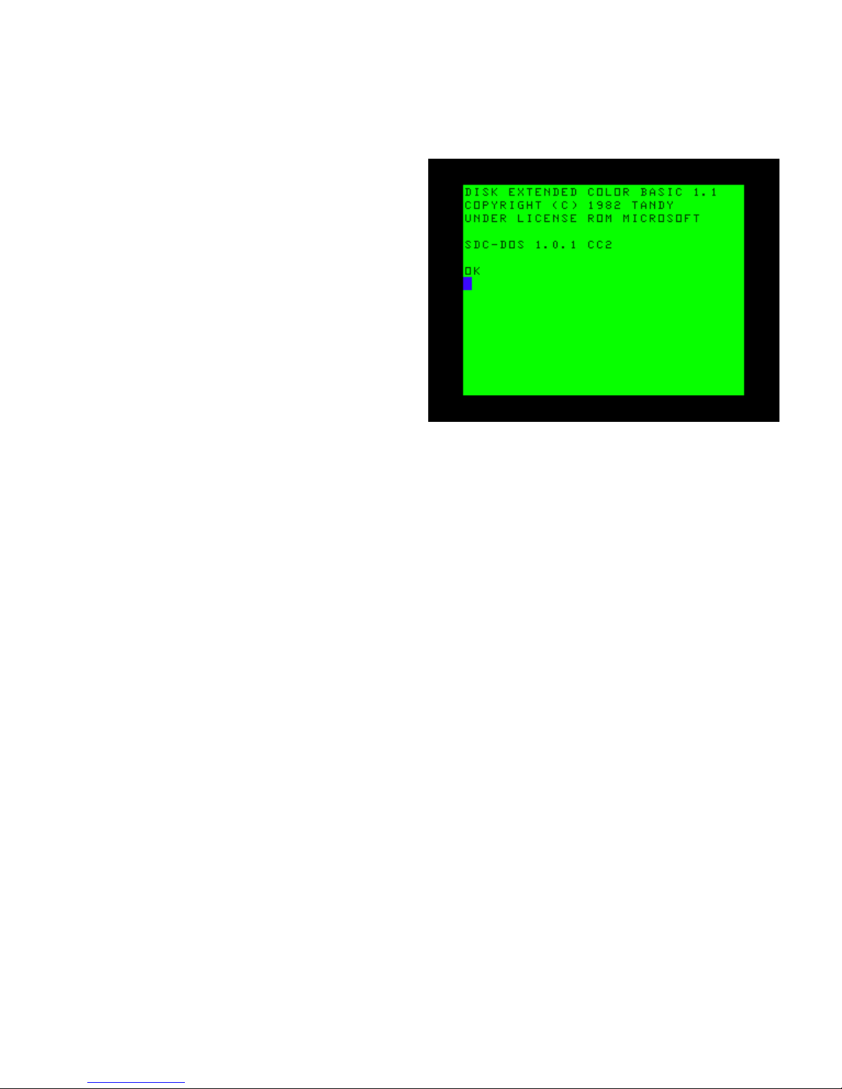
Press the D key to perform an installation of
SDC-DOS. is will rst load the ROM image
into memory and ask which of the 8 Flash
banks should be used as the destination. You
may install over the version of SDC-DOS
that is currently running if so desired. When
installation is complete the CoCo will re-boot
using the newly installed version (switching
banks if necessary).
Boot screen for SDC-DOS.
Rescuing After a Failed Update
is is mostly for folks who have attempted
an update on a D or E board CoCo 1, and
ended up with a CoCo SDC that will only
boot to DECB. e recovery steps should be
performed on either a modied D or E board
CoCo 1, a CoCo 2, or a CoCo3 – as long as
the DIR command hasn’t been issued with any
arguments prior to attempting the update.
Page 13

COCO SDC | 9
Before we get to the actual steps, it might
help to understand a little about the boot
process of the CoCo SDC. Mounting a disk
image is actually a task performed by the
Atmega micro-controller, not SDC-DOS.
e commands embedded in SDC-DOS tells
the Atmega to mount the disk images at the
location you specify. However, if your CoCo
SDC crashes aer an update attempt, it’s likely
you will not be able boot to SDC-DOS if
you chose to over-write bank 0 of your Flash
memory.
e way around this is to use a le the Atmega
will automatically mount when the CoCo is
rst powered on. e STARTUP.CFG le is this
le. If you create an ASCII text le named:
STARTUP.CFG
…and save it to the root of your SD card, the
Atmega micro-controller will read that le at
boot. e STARTUP.CFG le must contain the
following line in order cause the Atmega to
automatically mount the SDC101.DSK le:
0=SDC101.DSK
When this le is read by the Atmega microcontroller at boot, the CoCo SDC is already
mounted to the SDC101.DSK.
DO NOT COMPLETE THE FOLLOWING
PROCEDURES ON AN UNMODIFIED D
OR E BOARD CoCo 1!
Recovery Steps
In order to recover from this condition, use the
following steps:
1. Create the STARTUP.CFG le as described
earlier
2. Copy STARTUP.CFG to the root of the SD
card on a PC or Macintosh
3. Change the CoCo SDC DIP Switches to select
bank 1 (for DECB)
4. Place the SD card in the slot on the CoCo
SDC.
5. Make sure your CoCo is turned OFF!
6. Insert the CoCo SDC into the cartridge port
of your Color Computer.
7. Turn on your CoCo.
8. Enter the DIR command (with no arguments
if you’re using a CoCo3 – just to be safe).
9. Enter RUN “UPDATE” and follow the
prompts.
10. Your CoCo SDC should now be back to the
way it was when it was shipped to you.
You can test this by powering down your
CoCo, setting the DIP Switches back to bank
0, and restarting your CoCo. It should boot up
to the DECB message with the SDC-DOS and
version label.
Page 14

10 | Chapter 2
Page 15

COCO SDC | 11
3
Using the SDC
If you had to go thru the CoCo SDC update
process, then you already are familiar with
one of the enhanced commands. As stated
earlier, SDC-DOS is yet one more version of an
extended or patched DECB.
DRIVE - The Status
DRIVE has several uses. It’s rst and most basic
use is to provide a display of the current drive
conguration and status.
Typing DRIVE on your CoCo with the SDC
plugged into it should give you a display of the
drive mappings that resembles this:
0: ON GAMEPAK1.DSK 0
1: OFF ---- 0
2: ON DW #0 2
3: ON DW #0 3
Each line in the table shows the current
mapping information for one of the four logical
drive numbers. e rst column represents that
drive number.
e second column in the table indicates
whether or not Disk Image mode is currently
on or o. When Disk Image mode is o,
the corresponding real oppy drive will be
used instead. Assuming a oppy controller is
present.
e third column identies the current Disk
Image being mapped to the drive number.
ere are two possible congurations for this:
1. For an image located on an SD card this will
be the name of the image le. (Only the name
of the disk image will appear here, not the full
directory path)
2. For a Drivewire image this will be “DW #n”
where n is a Drivewire server virtual drive
number.
e fourth column shows the index of the
current virtual oppy disk within the larger
‘hard disk’ image le (0 - 255).
DRIVE is also used to assign disk images to
drives on the CoCo – real drives or virtual
drives.
Page 16

12 | Chapter 3
DRIVE – Mounting SD Based Images
e DRIVE command is multi-faceted. As
stated above, issuing just the DRIVE command
will give you a status on the CoCo SDC’s drive
mapping. However, the DRIVE command, as
displayed in the SDC-DOS updating section,
also instructs the Atmega micro-controller to
map the disk images stored on the SD card to a
virtual drive.
e proper context for the command is:
DRIVE n, “path name”
Where n is the drive number; path name is the
folder that holds your target disk image.
For example, issuing:
DRIVE 0, “APPS/TW64/TW64.DSK”
Would tell the Atmega to map DRIVE 0 to the
TW64.DSK image in the folder listed in the
path name.
Another example; let’s say you want to play
Pitstop II, on the PITSTOP.DSK image, located
in the Epyx folder under games. e command
you would issue is:
DRIVE 0, “GAMES/EPYX/PITSTOP.
DSK
Entering the DIR command would display a list
of the les on the disk image, just like it would
with real oppy hardware. You can LOAD &
RUN or LOADM & EXEC just as you would
with conventional hardware.
Multiple Disks
As discussed earlier, one of the features
CoCo SDC has over products that preceded
it to market is the ability to use soware that
contains multiple disks, as well as soware that
uses non-standard DSKCON routines.
In order to use games and applications that
utilize multiple disks, the CoCo SDC has a way
of knowing when this is necessary. e disk
images for multi-disk games and applications
need to be located in the same folder, and
the last character of the disk title must be a
number. An example from early will be used –
Sinistaar.
Entering the following command:
DIR “GAMES/SUNDOG/COCO3/SIN
STAR/
Returns the following:
Now, to mount the rst disk image in the
folder, simply enter:
Page 17

COCO SDC | 13
DRIVE 0, “GAMES/SUNDOG/COCO3/
SINSTAR/”
When the CoCo SDC mounts this image, the
red LED on the SDC will blink one time –
indicating that the lowest numerical disk in
the folder has been mounted – in this instance,
one. Entering the DIR command now will
result in SINSTAR1.DSK’s directory:
From here, you would RUN “SINSTAAR” to
load and run the game. When prompted for
disk number two, simply push the button on
the CoCo SDC, next to the SD slot, one time.
e red LED will blink twice indicating that
disk two is now selected. Follow the prompts
on screen each time the game or application
asks for the next disk, press the CoCo SDC
button to select the next numerical disk and
continue.
DRIVE – With Wildcards
Wildcard characters (* and ?) can be used in
the le portion of the path name but not in
the directory portion(s). Assuming there were
no other les in the GAMES directory whose
name started with the letters CH, the above
command could be shortened to:
DRIVE 0,”GAMES/CH*.DSK
You may also omit the extension from the
le name. In this case the system will rst try
to mount a le with the given name that has
no extension. If no such le exists then .* is
substituted for the missing extension and the
system uses the rst wildcard match, if any.
is means the above command could be
further shortened to:
DRIVE 0,”GAMES/CH*
Startup Conguration File
Entering a DRIVE command every time
you start up the CoCo can be inconvenient,
especially if you tend to use a particular disk
image le on a regular basis. To alleviate this
problem you can add a startup conguration
le to the SD card.
You will need to use a computer with an SD
card reader to create a plain-text ASCII le in
the root directory of the SD card. e name of
the le must be “STARTUP.CFG”. e contents
of the le may contain lines of text which
specify the initial mount points for drives 0
and/or 1 as shown in the example below.
0=Nos9Lev2.dsk
1=Utils.dsk
Page 18

14 | Chapter 3
You can also specify the path name of the
directory to be set as the Current Directory:
D=/CoCo/Games
Make sure all le and path name components
conform to the 8.3 naming conventions.
DIR
Let’s say you have an SD card arranged into
folders, and you want to load one of your
favorite games, but you cannot remember
for sure which folder the image is in. at’s
where the DIR command will come into play.
e DIR command in SDC-DOS works very
much like DIR in DECB, in that it gives you a
directory listing of the current disk – be it a real
oppy disk or a disk image assigned to a drive
using the DRIVE command.
Just entering DIR aer rst powering on the
CoCo, with the CoCo SDC inserted will most
likely end in an I/O? error since no image was
mounted. is may not be the situation if you
had to use the STARTUP.CFG le discussed
earlier, so we’ll start with the assumption of no
mounted disks.
When used with an SD/SDHC card, entering:
DIR -
Will result in a directory listing of the root of
the card as shown below, including any les,
disk images or folders:
DIR results of SD Card.
You can also look into folders to see what disk
images reside inside them. For example, I know
that Sinistaar by Sundog Soware is a child
folder to the Sundog folder. Using the following
command, you can work down to nd out what
the disk names are for Sinistaar:
DIR "GAMES/"
Lists the les and folders in the GAMES folder.
DIR "GAMES/SUNDOG/"
Lists les and folders in the GAMES/SUNDOG
folder.
DIR "GAMES/SUNDOG/COCO3"
You should have the picture by now…
DIR "GAMES/SUNDOG/COCO3/
SINSTAR/"
at last command will result in the following:
Page 19

COCO SDC | 15
DIR results of subdirectory of SD Card.
at is a lot of typing to pull a directory, but,
this depends solely on the le structure of your
SD card.
DIR can also use wildcard characters (* and ?).
For example, if you’re looking for disk image
and you only remember the rst few characters,
try:
DIR "GAMES/SIN*"
Which returns a list of games starting with the
characters SIN.
Further, you can also search for specic les
extensions.
For example:
DIR "MUSIC/*.ORC"
Returns a list of les with the ORC le
extension. Likewise, entering:
DIR "APPS/*.DSK"
Returns a list of disk image les in the APPS
folder.
Setting Current Directory
You can specify a Current Directory for
commands that access the SD card. Once
specied, all subsequent commands that refer
to les or directories on the SD card are relative
to the Current Directory unless the path name
begins with a slash (/).
Examples:
DIR = "GAMES/ACTION"
DIR = ".."
DIR = "/"
Explaining DIR
Information displayed by the DIR command
for each item is presented as 4 columns; Name,
Extension, Lock Status and Size.
CASINO DSK - 157K
EGYPT SDF - 228K
GAMEPAK1 DSK L 157K
GAMEPAK2 DSK - 157K
GR2K <DIR>
When an L appears in the third column
instead of a hyphen (-), it indicates that the
le is locked. A locked disk image may still be
mounted, but you cannot make changes to its
contents. Any attempt to use commands such
as SAVE or KILL on a locked image will result
in a ?WP ERROR.
For les, the fourth column displays the size of
the le in kilobytes. For directories, the fourth
column simply displays <DIR>.
Page 20

16 | Chapter 3
Locking Disk Images
ere are several way to mark a le as read
only. Primarily, the CoCo SDC honors the FAT
16/32 read only attribute.
On Mac OS X this is accessible by choosing
“Get Info” from the le menu while the le is
selected. In the resulting window turn on the
“Locked” check box.
On Windows, les can be lock by displaying
the Properties and clicking the “Read-only”
check box.
In addition, the SDF and VDK le formats
include an internal value to mark the image as
read only.
Creating New Disk Images
You can create a new, blank disk image le
on the SD card by adding the word NEW as a
nal parameter to the DRIVE command. If the
specied le already exists it will not be erased
or replaced.
DRIVE 0,"SYSTOOLS.DSK",NEW
To create a single sided disk image in the SDF
format use the NEW+
1
option.
DRIVE 0,"SEVENLNK.SDF",NEW+
To create a double sided, 40 track, disk image
in the SDF format use the NEW++ option.
DRIVE 0,”SEVENLNK.SDF”,NEW++
1 In SDC-DOS 1.2 the system was changed to create 40 track SDF images instead of 35 Track.
A new SDF disk image is like an un-formatted
oppy disk. You will need to use the DSKINI
command to format the SDF image otherwise
all disk operations will result in IO errors.
Ejecting a Disk Image
In most cases it is not necessary to eject disk
images under SDC-DOS. To switch disks you
can simply mount a new image in place of an
existing one. One situation where the need to
eject does arise is when you want to move an
image to a dierent drive number.
For example, if you try to mount an image in
drive 1 that is already mounted in drive 0, the
system will produce an ?AO ERROR (already
open). To accomplish this you must rst eject
the image from drive 0 by using the UNLOAD
argument in the DRIVE command:
DRIVE 0,UNLOAD
Using the CoCo SDC with Drivewire
Having the functionality of storing and
accessing your disk images right from an
SD card is great. e possibilities are almost
endless. However, the CoCo SDC is not a one
trick pony.
Page 21

COCO SDC | 17
Years ago Drivewire was released to act as a
disk image le server for Color Computer
users. With the Drivewire Server soware
running on a PC or Mac as a server application,
a user could connect to their Color Computer
to the server machine bit banger ←→ COM port
and viola, you could change disk images at will
on the server, while being able to run almost all
of your favorite soware.
e CoCo SDC has the Drivewire protocol
already built in, and will communicate with
a PC or Mac running the Drivewire server
soware.
Connecting via the Color Computer
To access disk images on the Drivewire server,
you use the DRIVE command as previously
explained; instead of a string argument
identifying an image le on the SD card, you
provide a Drivewire virtual drive number
(prexed with #) in the range of 0 to 63:
DRIVE 2,#0
If you have a virtual ‘hard disk’ image
containing an array of up to 256 oppy images,
you can specify the index of the desired oppy
image as a third argument to the DRIVE
command:
DRIVE 2,#0,125
What this does is assign whatever disk image
you have pre-loaded in Drivewire to virtual
oppy #2 in SDC-DOS. ats all. You cannot
actually change the disk image from SDC-DOS.
Of course in Drivewire, you need to have disk
images assigned to a oppy disk. Once the
CoCo SDC has been assigned to a Drivewire
disk position, you can switch disks at will with
the Drivewire GUI on the host computer.
It should be stated here that Drivewire was
created for use with HDB-DOS, a product
developed and sold by Cloud 9.
ere is no support in SDC-DOS or the CoCo
SDC for sending a signal over the cable asking
Drivewire to switch disk images. Of course
if you have the server running on a nearby
PC you should be able to use the server’s UI
to do this, allowing you to use games and
applications that reside on multiple disks.
It should also be pointed out that Drivewire
support in SDC-DOS was provided more as
a convenience feature for transferring les
between a PC and the SD card. You don’t get
quite the same feature-set that HDB-DOS
provides.
An example of this would be if you wanted
copy a disk image – let’s say Flight Simulator
II – from your PC to the CoCo SDC. e steps
you would take are:
Mount the FSII disk image to Drive 0 in
Drivewire.
Create a new oppy image on the CoCo SDC
with the following command:
DRIVE 0, "GAMES/FSII.DSK",NEW
Assign the CoCo SDC drive 1 to the Drivewire
server with the following command:
Page 22

18 | Chapter 3
DRIVE 1, #0
Finish the process by entering the following
command:
BACKUP 1 TO 0
Finally, the oppy controller emulation features
of the CoCo SDC are only available to images
located on the SD card. e Drivewire support
is aected by the same compatibility issues
that apply to HDB-DOS or CoCoNet since it is
implemented completely in soware by SDCDOS.
If you run a program which has its own oppy
I/O routines from an image on the Drivewire
server, it will run until the point where those
routines are rst executed. At that time the
CoCo SDC will detect that the oppy hardware
is being accessed and try to translate it to the
corresponding SD card image (if any). is
would be indicated by the red LED on the
CoCo SDC turning on and staying on when the
disk access would normally occur, causing your
Color Computer to enter into a locked state.
Accessing Real Floppy Disks
In addition to disk images located on SD cards
and the Drivewire server, SDC-DOS will also
provide access to real oppy disks if you have
a Mult-Pak Interface and a separate oppy
controller. When powering-up the system,
the switch on the MPI must be set to the slot
number containing the CoCo SDC board.
SDC-DOS will examine the hardware plugged
into the MPI looking for the highest numbered
slot containing a oppy controller. If found,
the oppy controller will be used for any drive
number in which Disk Image mode has been
turned o.
To turn o Disk Image mode for a particular
drive number and thereby utilize the oppy
controller, specify OFF as the second argument
in the DRIVE command:
DRIVE 1,OFF
Turning o Disk Image mode disables any
SD card image or Drivewire image currently
mounted under the specied drive number,
but does not eject (unload) the image. You can
reestablish access to the underlying image by
simply turning Disk Image mode back on for
that drive:
DRIVE 1,ON
Automatic Program Execution
When SDC-DOS starts following power-on or
cold reset, it will search the RS-DOS formatted,
mounted disk images (as specied in the
STARTUP.CFG le) for a BASIC program le
named “AUTOEXEC.BAS”. If such a le is
found, it will be automatically loaded and run.
You can hold down the SHIFT key to bypass
this feature.
Page 23

COCO SDC | 19
EXP
e EXP command has been added to provide
quick access to a program for browsing the
contents of the SD card (Explorer utility).
Entering the EXP command will cause the
system to search the root directory of the SD
card for a disk image named SDCEXP.DSK.
If found, the disk image will be automatically
mounted in drive 1. If the disk image contains a
BASIC program named AUTOEXEC.BAS then
it will be automatically loaded and run.
You can use this command to start e SDC
Explorer program described here: http://
cocosdc.blogspot.com/p/sdc-explorer.html
DEF DW = n
You can now change the DriveWire speed
conguration by using the DEF DW=n
command. Specify the CoCo platform number
(1, 2 or 3) as the value for n to select the desired
speed:
n Speed Comment
1 38,400 bps
2 57,600 bps Faster op-amp required to
work correctly on a CoCo1
3 115,200 bps CoCo 3 only
When running on a CoCo 1 or 2 you cannot
specify 3 as the parameter since those machines
are not capable of running at true doublespeed.
Page 24

20 | Chapter 3
Page 25

COCO SDC | 21
4
Using the Flash
An issue involving Flash programming on a
CoCo 1 has been discovered.
Please see Chapter 2, section “D & E
Compatibility Issues” for details.
e CoCo SDC contains 128K of Flash
memory which is divided into eight banks
of 16K. All eight banks of the Flash are userprogrammable. e board is provided with
SDC-DOS pre-programmed into bank 0 and
stock Disk BASIC 1.1 in bank 1. SDC-DOS
adds extensions to the Disk BASIC commands
which make it easy to take advantage of the
Flash memory.
Care should be taken when using these
commands to avoid accidental destruction
of data. You should always keep copies of
the Flashed data elsewhere so it can be reprogrammed if necessary.
Running a Cartridge Image
e Flash memory will typically be used
to hold images of cartridge-based soware
(Program Paks).
e RUN command in SDC-DOS has been
extended to facilitate the execution of a
cartridge image from any of the 8 Flash banks.
Simply pass the bank number, prexed with
the @ character, as an argument to the RUN
command.
RUN @2
is has the eect of activating the specied
bank and performing a cold re-boot of the
CoCo. If the rst two bytes of the cartridge
image are “DK” then the normal start-up
process occurs, allowing Extended BASIC to
transfer control to the cartridge image at C002
during initialization. If anything else appears
in the rst two bytes then control is transferred
to C000 immediately aer the hardware is
initialized.
Normally, pressing the RESET button on the
CoCo will re-activate the Flash bank set by the
DIP switches on the CoCo SDC board. You can
force the system to retain the bank selection of
the RUN command by suxing the command
with ,R:
RUN @2,R
Page 26

22 | Chapter 4
Aer using this option you will need to
fully power-down the CoCo (and Multi-Pak
Interface) in order to restore the normal Reset
behavior.
Erasing Banks and Sectors
e active Flash bank appears in the CoCo
memory map from C000 to FEFF. Each of the
16K banks is further divided into four sectors
of 4K:
Sector Address Range
0 C000 - CFFF
1 D000 - DFFF
2 E000 - EFFF
3 F000 - FEFF
On a CoCo 3, the last 256 bytes (FE00 to FEFF)
are not accessible using SDC-DOS 1.2 or
earlier.
e Flash chip uses the sector divisions for
erase operations. Before programming data
into the Flash, the sectors to be programmed
should rst be erased. Erasing the ash has the
eect of setting all bits to ‘1’ resulting in byte
values of FF. e KILL MEM command can be
used to erase a single sector or an entire bank.
Erase all four sectors of bank 3:
KILL MEM @3
Erase only sector 2 of bank 6:
KILL MEM @6,&HE000
When erasing a single sector you can specify
any address from C000 to FEFF. e entire
sector containing that address will be erased.
You are not allowed to erase any part of the
active bank (the one from which SDC-DOS is
running).
Writing to the Flash
Writing data to the Flash involves a process
where one or more bits in a byte are cleared to
‘0’. Once a bit has been cleared it can only be
changed to a ‘1’ through an Erase operation.
e WRITE MEM command is used to
program one or more bytes.
WRITE MEM @bank, source, desti
nation, count
@bank Bank number in which the data
will be written (0-7)
source Starting address of the source
data
destination Address in the Flash where
the data will be written (C000FEFF)
count Number of bytes to write
e count argument will be clipped if necessary
to prevent writing past the end of the Flash
address space.
Page 27

COCO SDC | 23
Copying a Block of Memory
When creating a utility program to manage
the Flash, one feature that is oen needed is
the ability to quickly move a block of memory.
Consider the situation where you wanted to
copy the contents of one Flash bank to another.
is would require that data from the source
bank rst be copied to a temporary buer in
RAM before writing it to the destination bank.
e COPY MEM command has been provided
for this purpose.
COPY MEM [@bank,] source, desti
nation, count [USING slot]
@bank e Flash bank number to
activate during the copy (0-7)
source Starting address of the source
block
destination Address where the block will
be copied to
count Number of bytes in the block
USING slot e Multi-Pak Interface slot to
activate during the copy (1-4)
e bank and slot arguments are both optional
and mutually exclusive. You can provide one or
the other, but not both. e bank argument can
be provided when you are copying data from
a specic Flash bank on the CoCo SDC board.
e slot argument allows you to copy data from
the ROM of another cartridge when using a
Multi-Pak Interface.
Be careful when using the COPY MEM
command as it can easily crash the CoCo if
a block is copied to a location used by the
system.
e BASIC program listing below shows how
to copy the contents of a ROM cartridge into
one of the Flash banks of the CoCo SDC.
e example assumes an MPI is attached and
the CoCo has at least 32K RAM. It does not
perform any validation of the input parameters.
10 CLEAR 200,&H3FFF ' RESERVE A
16K RAM BUFFER AT $4000
20 INPUT "COPY FROM MPI
SLOT";SL
30 COPY MEM &HC000,&H4000,16384
-256 USING SL
40 INPUT "DESTINATION BANK";BK
50 KILL MEM @BK ' ERASE BEFORE
WRITE
60 WRITE MEM @BK,&H4000,&HC000,
16384-256
Page 28

24 | Chapter 4
Page 29

COCO SDC | 25
5
About File Formats
e CoCo SDC supports four dierent disk
image formats. e primary format is referred
to as the DSK format and can be used for the
imaging of both oppy disks and hard disks.
e secondary format, known as SDF, was
created specically for the CoCo SDC and is
used for imaging oppy disks only. e third is
the JVC format. e fourth is VDK, popular for
use with Dragon emulators.
No special name or extension need be assigned
to an image le for the purpose of format
determination. When a disk image is mounted
the rmware detects which format the image
uses by examining the le to see if it contains
an SDF format signature. Nevertheless it is
recommended that an extension which is
indicative of the image format be used for
identication by humans.
DSK Images
e DSK image format is named for the
extension most commonly appearing on such
les. Images in this format consist of a simple
sector array with each sector being 256 bytes in
length. is is the most common format used
in the CoCo world.
In order to be recognized as a valid DSK
image, the le size must be an exact multiple
of 256 bytes. e minimum le size is 82,944
bytes which is equal to 324 sectors or 18
tracks of a single-sided CoCo disk (enough to
accommodate the Disk BASIC directory track).
e disk geometry associated with a DSK
image is determined by the le size. For oppy
images the number of sectors per track is
always 18. ere are either one or two tracks
per cylinder (equal to the number of sides) and
a maximum of 80 cylinders. e largest le
size for a oppy image is 737,280 bytes or 2880
sectors (double-sided 80 cylinders).
Page 30

26 | Chapter 5
An image with more than 2880 sectors is considered to be a hard disk. If a hard disk image is
accessed using the oppy interface mode, only the rst 1440 sectors can be used. In this situation
those sectors are accessible as a single-sided 80 track oppy disk. e controller’s LBA interface
mode must be used to access sectors beyond the rst 1440 in a hard disk image.
JVC Images
is disk image format is an array of sectors with a 1 to 4 byte header prepended to the front. e
header bytes are described in the following table:
Byte Oset Length Description
0 1 Sectors Per Track. Default is 18.
1 1 Side Count. Default is 1.
2 1 Sector Size Code. Default is 1 (256 bytes per sector).
3 1 First Sector ID. Default is 1.
All of the bytes are optional, but are interpreted in the order listed in the table. If omitted their
default values are assumed. e CoCo SDC requires the Sectors Per Track to be 18, and the Sector
Size Code to be 1. It will honor a Side Count of 1 or 2.
VDK Images
is is also an array of sectors prepended by a header.
Disk Geometry Table for DSK Images
File Size in Bytes Sectors Disk Type Cylinders Sides
Less than 82,944 <324 Invalid
184,320 or less ≤ 720 FD 40 1
368,640 or less ≤ 1440 FD 40 2
737,280 or less ≤ 2880 FD 80 2
737,536 or more > 2880 HD 80* 1*
* only when accessed through the oppy interface mode
Page 31

COCO SDC | 27
Byte Oset Length Description
0 2 ASCII ‘d’ and ‘k’.
2 2 Header size (little-endian).
4 1 Version of VDK format.
5 1 Backwards compatibility version.
6 1 Identity of le source.
7 1 Version of le source.
8 1 Number of tracks.
9 1 Number of sides.
10 1 Flags:
Bit Meaning Bit Meaning
0 Write Protect 1 Advisory lock
2 Mandatory Lock 3 Disk Set
4 Unused 5 Unused
6 Unused 7 Unused
11 1 Compression ags and name length.
e CoCo SDC will honor a Number Of Sides value of 1 or 2. It will also honor the Write Protect
bit.
SDF Images
e SDF image format is used to represent oppy disks that have a non-standard layout which is
anything other than 18 sectors per track and 256 bytes per sector using standard numbering of
the tracks and sectors. e SDF format is similar to the DMK format supported by most CoCo
emulators. It has been augmented to provide better performance within the limited resources of
the Atmega328 micro controller.
e dmk2sdf program has been created for converting a DMK image to the SDF format. A Win32
command line executable along with the ANSI C source code can be downloaded using the link:
https://goo.gl/q61D6s.
Page 32

28 | Chapter 5
SDF File Format
An SDF le consists of a header followed by a variably-sized array of track records. e track
records are arranged in ascending order corresponding to their physical position on the disk
(cylinder and side).
SDF FILE
File Header
Single Sided
Track Order
Double Sided
Track Order
Cylinder 0
Cylinder 1
Cylinder 2
Cylinder 3
Cylinder 0 / Side 0
Cylinder 0 / Side 1
Cylinder 1 / Side 0
Cylinder 1 / Side 1
Track
Records
512
bytes
SDF Track Records
6656 bytes
per Track
•
•
•
•
•
•
Contents of the SDF 512 byte File Header
Byte Oset Length in
Bytes
Description
0 4 Format signature and version string. e ASCII characters ‘SDF1’
appear at the beginning of the le to identify it as a version 1 SDF
image. e numeric character may be incremented in future versions.
4 1 Number of cylinders (80 max).
5 1 Number of sides (1 or 2).
6 1 Write permission: 0x00 = Read/Write ; 0xFF = Read-Only.
7 1 Nested sectors ag: 0x00 = NO ; 0x01 = YES. is byte is set to 0x01
if the disk is known to use a copy-protection scheme in which the ID
eld for one sector is contained within the Data eld of another.
8 504 Reserved. All remaining bytes in the header should be set to zero.
Page 33

COCO SDC | 29
Following the File Header is the array of Track Records. Each track record begins with a 256
byte header and is then followed by 6250 bytes of raw track data. ere are 150 bytes of unused
padding at the end of a track record which are included to align every track on a 512 byte
boundary within the le.
SDF Track Record
Track Header
Sector
ID Table
Sector Entry 0
Sector Entry 1
Sector Entry 2
Sector Entry 30
•
•
•
Track Header
Info Record
Sector
ID Table
Raw
Track Data
Padding
256
bytes
8 bytes
248
bytes
6250
bytes
150
bytes
8 bytes
per Entry
e xed track size of 6250 bytes can accommodate either a single-density (125 kbps) or doubledensity (250 kbps) track at 300 rpm. e SDF format does NOT support 8 inch oppy disks or
high density (500 kbps) images.
Any part of a track which is recorded in single-density has each byte written twice in succession.
is preserves the correct spacing of data on mixed-density tracks.
Contents of the SDF 256 byte Track Header
Byte Oset Length in
Bytes
Description
0 1 Number of used entries in the Sector ID Table.
1 7 Reserved. All seven of the remaining Info Record bytes should be set
to zero.
8 248 Sector ID Table.
Each entry in the Sector ID Table is 8 bytes in length and contains information about one sector
recorded on the track. e total size of the table is 248 bytes and can accommodate a maximum of
31 sector entries for a single track. All used entries must appear sequentially from the beginning
of the table. e unused entries must be lled with zeroes and placed at the end of the table.
Page 34

30 | Chapter 5
Byte Oset Length in
Bytes
Description
0 2 e 14 low-order bits of this 16 bit eld contain the oset from the
beginning of the Track Record to the rst byte of the sector’s ID eld
within the raw track data.
e two high-order bits (14 and 15) are used as ags. Bit 14 is set for
a sector recorded in single-density. Bit 15 is set if the ID eld has an
incorrect CRC.
is 16 bit integer eld is stored in little-endian order (LSB rst).
2 2 e 14 low-order bits of this 16 bit eld contain the oset from the
beginning of the Track Record to the rst byte of the sector’s Data
eld within the raw track data.
e two high-order bits (14 and 15) are used as ags. Bit 14 is set if
the sector’s Data eld uses a Deleted Data Mark. Bit 15 is set if the
Data eld has an incorrect CRC.
is 16 bit integer eld is stored in little-endian order (LSB rst).
4 1 e Track Number byte copied from the sector’s ID eld.
5 1 e Side Number byte copied from the sector’s ID eld.
6 1 e Sector Number byte copied from the sector’s ID eld.
7 1 e Size Code byte copied from the sector’s ID eld.
Page 35

COCO SDC | 31
Page 36

32 | Chapter 5
Page 37

COCO SDC | 33
Page 38

34 |
Page 39

COCO SDC | 35
Index
A
Atmega 2
AUTOEXEC.BAS 18
B
BACKUP 18
C
capacitor 7
Cartridge 21
case 4, 7
D
‘D’ and ‘E’ boards 5
DEF DW = n 19
DIP switch 3
DIR 14, 15
Disk Geometry 26
dmk2sdf 27
Dragon 2
DRGN switch 4
DRIVE 11, 16
Drivewire 16, 18
Drivewire server 1
DSKCON 12
DSK format 25
E
Ejecting 16
Enclosure 7
Erasing Banks 22
EXP 19
Explorer utility 19
F
FAT16 3
FAT32 3
Flash 21
Flash memory 2
H
HDB-DOS 17
I
IDE 1
image formats 25
J
jumper 3
JVC 26
K
KILL 22
L
LED 3, 13
Locking Disk Images 16
M
Motherboard 6
MPI 6. SeeMulti-Pak Interface
Multi-Pak 6. SeeMulti-Pak Interface
Multiple Disks 12
Mult-Pak Interface 3
N
New Disk Images 16
O
OS9 1
R
Real Floppy 18
RUN 21
S
SCSI 1
SDC-DOS 7, 11, 12, 21
SDC Exporer 19
SDF 25, 26, 28
Startup 11
STARTUP.CFG 9, 14
system reset 4
V
VDK 26
W
Wildcards 13
Page 40

 Loading...