

Page 1
WARNING: FOR OUTDOOR USE ONLY
WARNING: If the information in this manual is not followed exactly, a fi re or explosion may result causing property
damage, personal injury or loss of life.
ELECTRONIC IGNITION SYSTEM
FIREBOWL OWNER’S MANUAL
MODELS: 54 and 68 LL & NL for LP & NG
DO NOT DISCARD THIS MANUAL
• Important operating and maintenance instructions included.
• Read, understand and follow these instructions for safe installation and operation.
• Leave this manual with party responsible for use and operation.
DO NOT STORE OR USE GASOLINE OR OTHER FLAMMABLE VAPORS & LIQUIDS IN THE VICINITY OF
THIS OR ANY OTHER APPLIANCE.
WHAT TO DO IF YOU SMELL GAS:
• Do not try to light any appliance.
• Do not touch any electrical switch; do not use any phone in your building.
• Immediately call your gas supplier from a neighbor’s phone.
• Follow the gas supplier’s instructions.
• If you cannot reach your gas supplier, call the fi re department.
INSTALLATION & SERVICE MUST BE PERFORMED BY A QUALIFIED INSTALLER, SERVICE AGENCY
OR GAS SUPPLIER.
WARNING: Improper installation, adjustment, alteration, service or maintenance can cause in-
jury or property damage. Read the installation, operating and maintenance instructions thoroughly
before installing or servicing this equipment.
COLOMBO CONSTRUCTION CORP
342 Park AVE Brooklyn, NY 11205
T 718.399.2233 F 718.399.2237 M 212.334.5069
firefeatures.com
Page 2

Page 3

HOT SURFACE IGNITION PILOT LIGHT
CONTENTS
TABLE OF CONTENTS
4
Technical Quick View
5
Warnings
7
Overview
10
Components
11
Pipe Preparation
12
Placing and Installing Bowl
13
Install Bowl
14
Install Burner
16
Place Pilot Assembly
17
Firebowl Ignition
18
Firebowl Shut Off
18
Emergency / Shut Off
19
Troubleshooting
20
Rocks
21
Maintenance
3
54 - 68 LL and NL ELECTRONIC IGNITION FIREBOWL
Page 4

HOT SURFACE IGNITION PILOT LIGHT
!
FOR OUTDOOR USE ONLY
Model: 54 - 68 LL and NL ELECTRONIC IGNITION FIREBOWL
OUTDOOR FIREPLACE
Type of Gas: Natural Gas (NG), Liquid Propane (LP)
ORIFICE SIZES:
NG Maximum BTU = 290,000 BTU @ 7” W.C. Inlet - 6” W.C. Manifold
LP Maximum BTU = 290,000 BTU @ 11” W.C. Inlet - 10” W.C. Manifold
INSTALLATION BY CERTIFIED GAS TECHNICIAN ONLY
TECHNICAL
QUICK VIEW
MINIMUM CLEARANCE TO COMBUSTIBLES: Top: 12ft (144”) - Sides: 2ft (24”)
INSTALLATION ON (OR OVER) NON-COMBUSTIBLE FLOORS ONLY.
TO LIGHT APPLIANCE:
NOTE: BEFORE OPERATING APPLIANCE ENSURE THE MANUAL GAS SHUTOFF VALVE IS OPEN.
1. PRIOR TO TURNING APPLIANCE ON
- VISUALLY INSPECT APPLIANCE TO ENSURE DEBRIS SUCH AS LEAVES OR OTHER COMBUSTIBLE MATERIAL
HAS NOT COLLECTED INSIDE THE APPLIANCE WHICH COULD BURN AND EMIT EMBERS ONCE THE APPLIANCE IS
TURNED ON.
- ENSURE ANY PERSON STANDING CLOSE TO THE APPLIANCE IS AWARE YOU WILL BE TURNING THE APPLIANCE
ON PRIOR TO ACTUALLY TURNING IT ON.
2. TURN APPLIANCE ON BY TURNING ON THE ELECTRICAL DEVICE USED TO POWER THE APPLIANCE.
SEQUENCE OF OPERATION DURING IGNITION
- POWER IS APPLIED
- HOT SURFACE IGNITER (GLOW PLUG) BECOMES HOT AND PILOT GAS VALVE OPENS
- WITHIN 10 SECONDS OF POWER APPLICATION PILOT FLAME SHOULD BE VISIBLE (AT NIGHT ONLY)
- WITHIN 10 SECONDS OF PILOT FLAME IGNITION, BURNER ELEMENT SHOULD IGNITE
IF MAIN BURNER DOES NOT LIGHT, OR YOU SMELL OR HEAR GAS, IMMEDIATELY TURN PLAIN VIEW
GAS VALVE TO OFF POSITION.
TO PUT OUT APPLIANCE:
TURN APPLIANCE OFF BY TURNING OFF THE ELECTRICAL DEVICE USED TO POWER THE APPLIANCE.
4
54 - 68 LL and NL ELECTRONIC IGNITION FIREBOWL
Page 5

HOT SURFACE IGNITION PILOT LIGHT
WARNINGS
!!!!
WARNING: IF YOU DO NOT FOLLOW THESE INSTRUCTIONS EXACTLY, A FIRE OR EXPLOSION MAY RESULT
CAUSING PROPERTY DAMAGE , PERSONAL INJU RY OR
LOSS OF LIFE.
• IMPROPER INSTALL ATION, ADJUSTMENT, ALTERATION, SERVICE OR MAINTENANCE CAN CAUSE INJURY
OR PROPERTY DAMAGE.
• INSTALLATION & GAS CONNECTION IS TO BE HARD
PIPE & MUST BE DONE BY A CERTIFIED GAS TECHNICIAN, QUALIFIED INSTALLER, SERVICE AGENCY OR GAS
SUPPLIER. FOR ASSISTANCE O R ADDITIONAL INFORMATION CONSULT A QUALIFIED INSTALLER, SERVICE
AGENCY, OR THE GAS SUPPLIER.
• THIS APLIANCE IS A DECORATIVE GAS APPLIANCE FOR
OUTDOOR USE ONLY AND MUST NOT BE USED FOR COOKING.
COLOMBO CONSTRUCTION CORP disclaims any responsibility
for, and the warrenty will be voided by the following actions:
• Installation & use of any damaged components.
• Modification of the burner & valve assembly.
• Installation other than as instructed by this Owner’s Manual.
• Installation and/or use of any component part not approved
by Colombo Construction Corp.
ANY SUCH ACTION MAY CAUSE A FIRE HAZARD.
FOR YOUR SAFETY READ BEFORE
OPERATING
Do NOT use this appliance if any part has been under water.
Immediately call a qualified service technician to inspect the
appliance and to replace any part of the control system and any
gas control which has been under water.
More frequent cleaning may be required as necessary. It is imperative that control compartment, burners and circulating air
passageways of the appliance be kept clean to provide for adequate combustion and ventilation air.
This appliance is only for use with the type of gas indicated
on the rating plate. This appliance is not convertible for use
with other gases.
The appliance and its individual shutoff valve must be disconnected from the gas supply piping system during any pressure
testing of that system at test pressures in excess of ½ psi.
The appliance must be isolated from the gas supply piping system by closing its individual manual shutoff valve during any
pressure testing of the gas supply piping system at test pressures equal to or less than ½ psi.
Children and adults should be alerted to the hazards of high
surface temperatures and should stay away to avoid burns or
clothing ignition. Young children should be carefully supervised when they are in the area of the appliance.
Clothing or other flammable materials should not be hung
from the appliance, or placed on or near the appliance.
Any guard or other protective device removed for servicing the
appliance must be replaced prior to operating the appliance.
The installation of this appliance must conform with local
codes or, in the absence of local codes, with the National Fuel
Gas Code, ANSI Z223.1.
Solid fuels are not to be burned in this gas appliance.
The appliance should be inspected before each use for debris,
damage, or corrosion, and at least annually by a qualified service person.
• INSPECT THE APPLIANCE & COMPONENTS.
• DO NOT INSTALL DAMAGED COMPONENTS.
• DO NOT INSTALL INCOMPLETE COMPONENTS.
• REPORT DAMAGED PARTS TO DEALER.
Use outside only in well ventilated area. Do not use inside
house, camper, tent, garage, vehicle or any type of un-vented or enclosed area.
Do not operate or place appliance on, near, or in the vicinity
of any flammable materials, vapors, liquids or accelerants of
any kind; including but not limited to: bottled gases, gasoline, kerosene, diesel fuel, oil, aerosol cans, paints, thinners,
solvents, sealants, lubricants, chemicals, plastics, petroleum
products, electronics, motors, vehicles, fertilizer, gun powder, ammunition, firearms, fireworks, fabrics, paper products, wood, dry vegetation etc.
Do not operate appliance during an electrical storm.
Appliance must be permanently secured on a stable and
level surface.
5
54 - 68 LL and NL ELECTRONIC IGNITION FIREBOWL
Page 6

HOT SURFACE IGNITION PILOT LIGHT
WARNINGS
!
Never operate while sleeping or unattended.
Before operating, smell all around the appliance for gas. Do
not operate if you smell gas.
WHAT TO DO IF YOU SMELL GAS OR SUSPECT A LEAK:
IMMEDIATELY SHUT OFF GAS TO THE APPLIANCE AND VENTILATE AREA. DO NOT STRIKE A MATCH, SMOKE OR CREATE
ANY FLAME OR ELECTRIC SPARK. FIND AND CORRECT ANY
LEAKS. USE A SOAP SOLUTION TO DETECT ESCAPING GAS.
DO NOT TOUCH ANY ELECTRIC AL SWITCH. DO NOT USE
ANY PHONE IN YOUR BUILDING. IMMEDIATELY CALL YOUR
GAS SUPPLIER. FOLLOW THE GAS SUPPLIER’S INSTRUCTIONS. IF YOU CANNOT REACH YOUR GAS SUPPLIER, CALL
THE FIRE DEPARTMENT.
• Use only your hand to turn the gas valve control knob on
the appliance. Never use tools. If the knob will not turn by
hand, do not try to force or repair it yourself. Call a qualified
service technician.
• Forced or attempted repair may result in a fire or explosion.
• Do not touch appliance or gas controls when in operation.
• Do not lean on or into appliance.
• Do not play on or around appliance.
FOR YOUR SAFETY READ BEFORE
OPERATING
LEAK TESTING PROCEDURE
• Perform a leak test at least once each year whether the gas
supply has been disconnected or not.
• Conduct a leak test anytime the gas supply is connected to
the regulator or any part of the gas system is disconnected
or replaced.
• As a safety precaution, remember to always leak test your
Fire Feature outdoors in a well-ventilated area.
• Never smoke or permit sources of ignition in the area while
doing a leak test.
• Do not use a flame, such as a lighted match to test for leaks.
Use only a leak testing solution as specified below.
Leak Testing Procedure:
1. Prepare a leak testing solution of sudsy water by mixing in
a spray bottle half-liquid soap and half water.
2. Check and make sure all the control knobs are in the OFF
position.
3. Turn gas supply valve counter clockwise one turn to open.
4. Apply leak-testing solution by spraying on joints of the gas
delivery system.
• Do not sit on or step into appliance.
• Do not put hands, feet or any body part on appliance, in
or near flame.
• Do not throw foreign objects or any liquids into appliance.
• Do not operate this appliance under the influence of alcohol or drugs.
This ap plia nce d oes not com e sup plied with rock s. Lava rocks
are recommended. Some rocks contain water and when
heated will crack, split or burst. Please consult your local
landscape supply for recommendations on which rocks are
best for fires.
• Those connections which could be disturbed when installing,
including, but not limited to the valve train, must be leak tested by a certified gas technician prior to use.
5. Blowing bubbles in the soap solution indicates that a leak
is present.
6. Stop a leak by tightening the loose joint or by replacing
the faulty part with a replacement part recommended by the
manufacturer. Do not attempt to repair the gas supply valve
if it should become damaged. The gas supply valve must be
replaced.
7. If you are unable to stop a leak, close the valve at the gas
supply. Call an authorized gas appliance service technician or
LP gas dealer. Do not use the appliance until the leak is corrected.
8. Push in and turn any control knob to release pressure in the
hose and manifold.
9. Turn off all gas valves and control knobs.
6
54 - 68 LL and NL ELECTRONIC IGNITION FIREBOWL
Page 7
HOT SURFACE IGNITION PILOT LIGHT
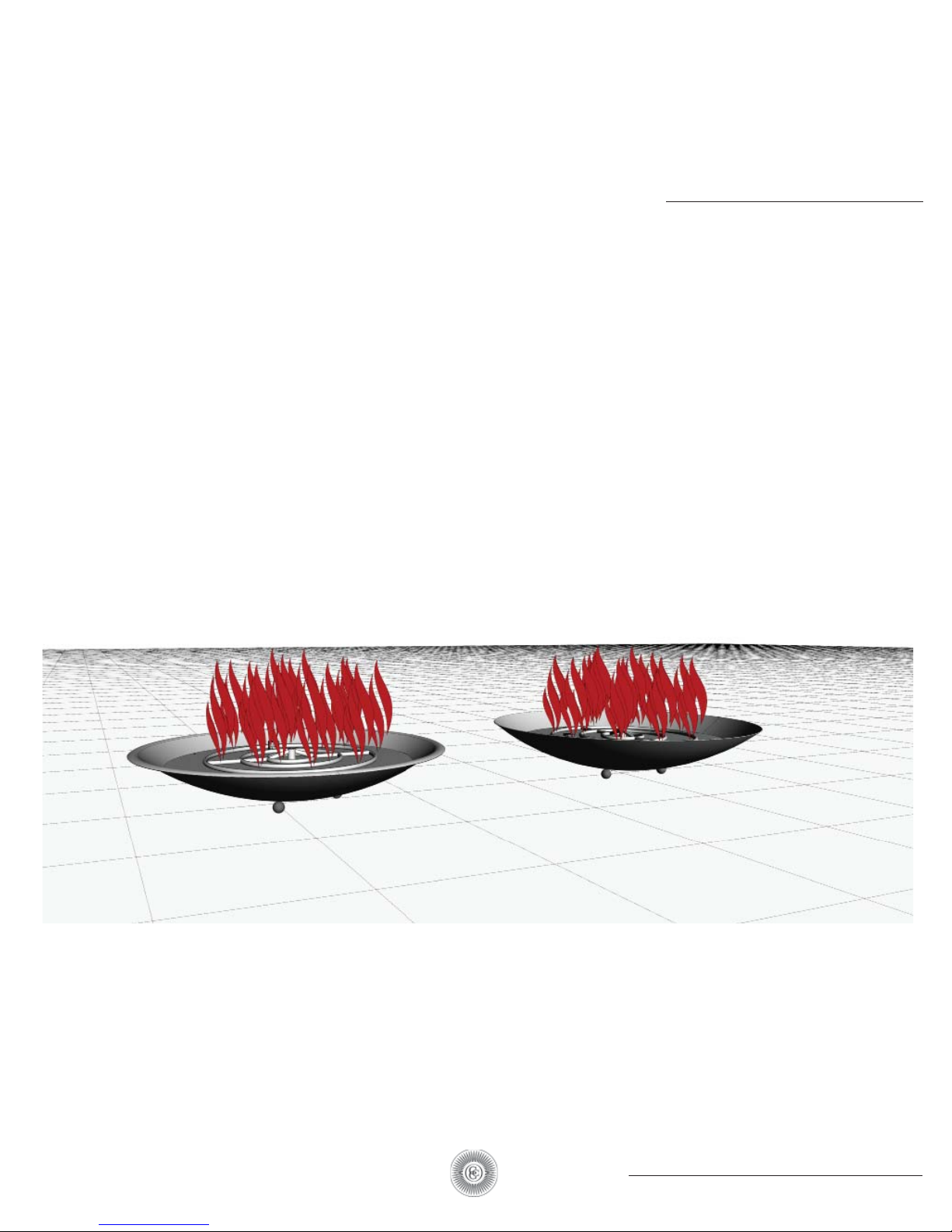
OVERVIEW
54LL and 54NL
68L and 68NL
ELECTRONIC IGNITION FIREBOWL
7
54 - 68 LL and NL ELECTRONIC IGNITION FIREBOWL
Page 8
HOT SURFACE IGNITION PILOT LIGHT
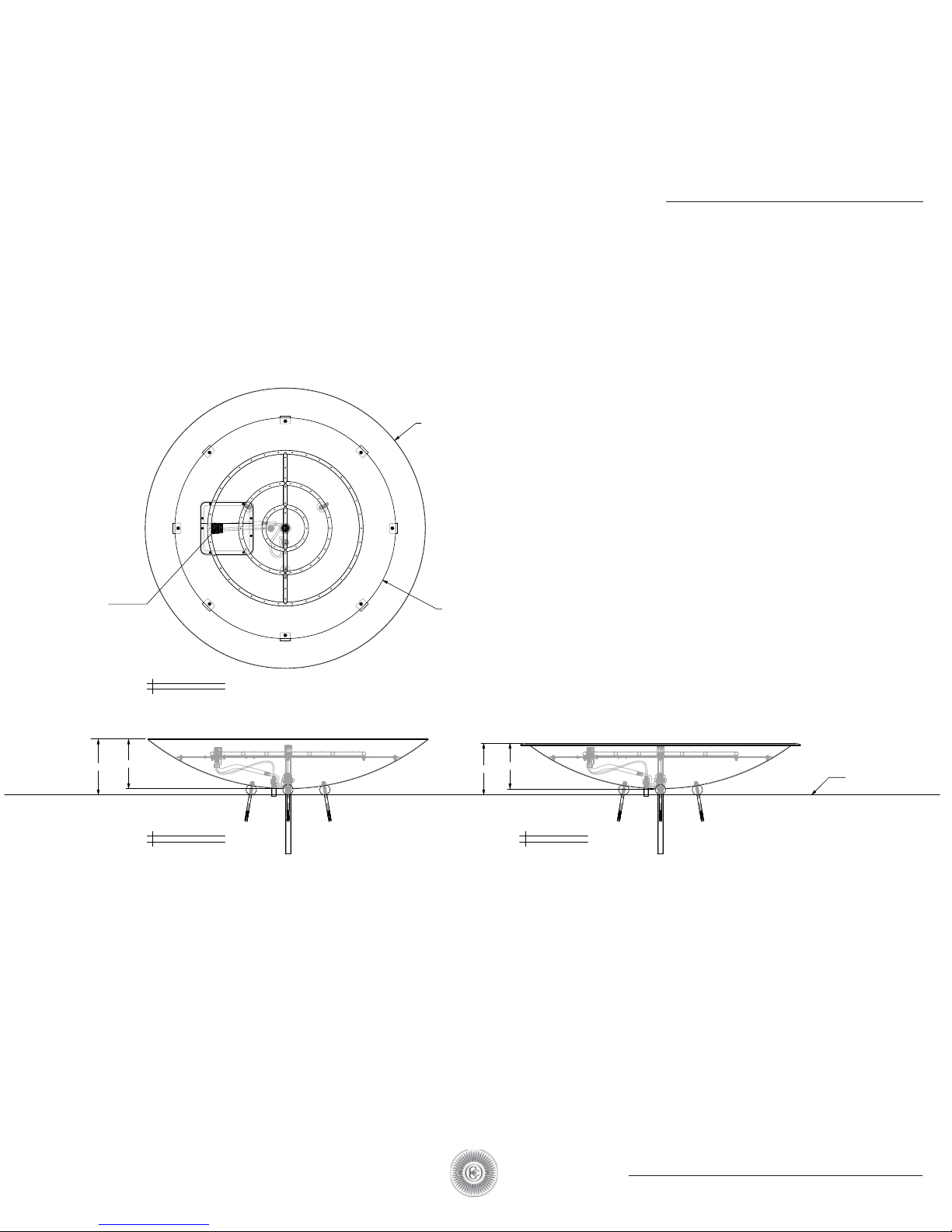
54" DIA
54NL AND 54LL FIREBOWL
OVERVIEW
54 LL AND NL 2 VIEW
PILOT ASSEMBLY
10 3/4"
9 1/2"
TOP VIEW
HEAT SHIELD
8 3/4"
10"
54LL SIDE VIEW54NL FRONT VIEW
FINISH GRADE
8
54 - 68 LL and NL ELECTRONIC IGNITION FIREBOWL
Page 9
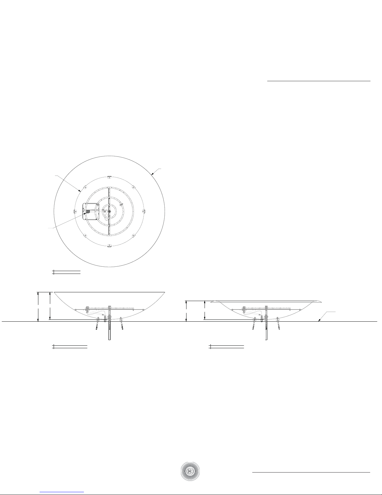
HEAT SHIELD
HOT SURFACE IGNITION PILOT LIGHT
68" DIA
68NL AND 68L FIREBOWL
OVERVIEW
68 L AND NL 2 VIEW
PILOT ASSEMBLY
18"
TOP VIEW
16 3/4"
68NL FRONT VIEW
12 11/16"
11 1/2"
68L FRONT VIEW
FINISH GRADE
9
54 - 68 LL and NL ELECTRONIC IGNITION FIREBOWL
Page 10
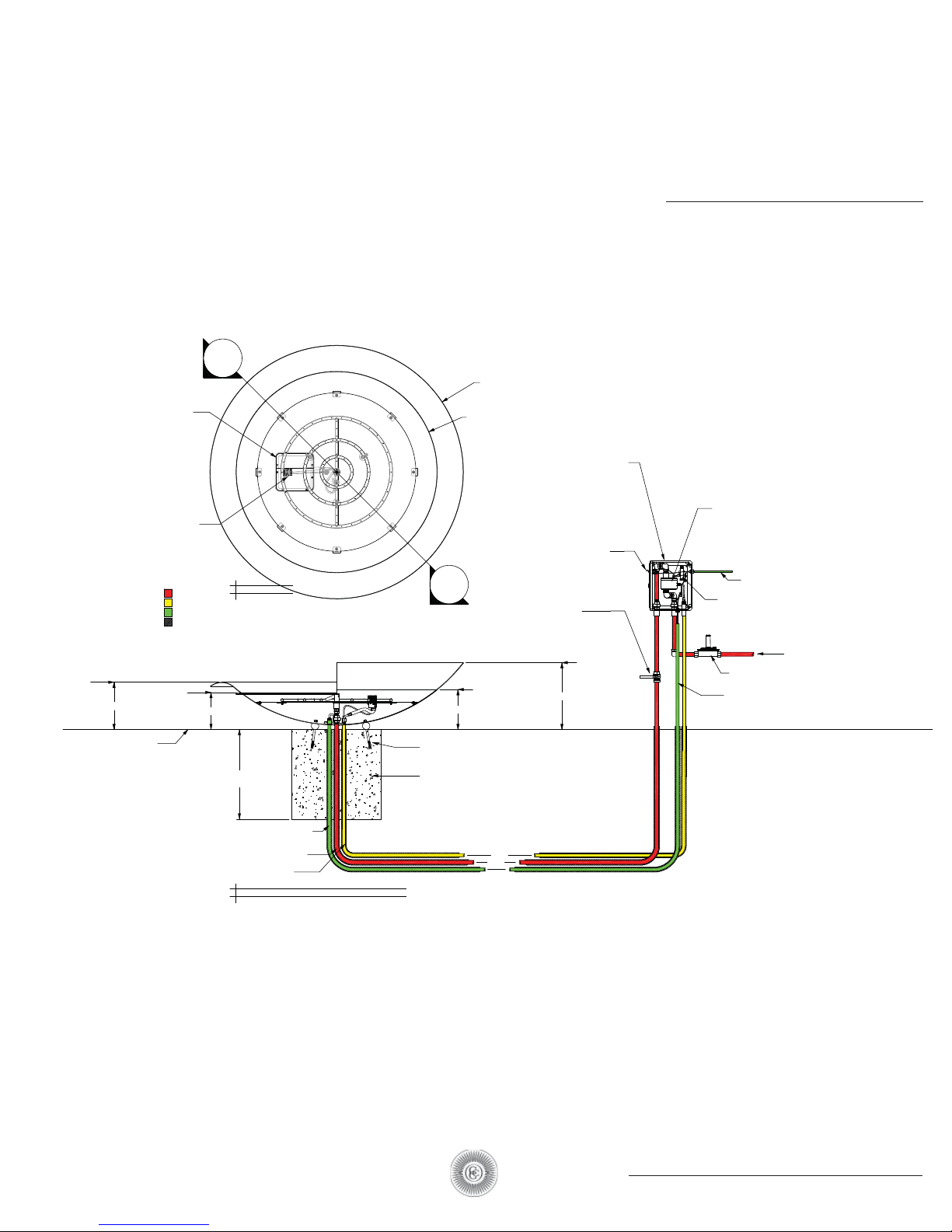
68L FIREBOWL
GAS SYSTEM ACCESS
PILOT BU RNER
54LL FIREBOWL
12 11/16"
A
SECTION
MAIN GAS
PILOT GAS
ELECTRICAL
SLEEVING GAS LINE
10"
TOP VIEW
HOT SURFACE IGNITION PILOT LIGHT
68FIREBOWL
WITH ELECTRONIC IGNITION
68" DIA
54FIREBOWL
WITH ELECTRONIC IGNITION
54" DIA
FIBERGLASS ENCLOSURE (NEMA 4X),
HINGED COVER WITH 1/4-TURN LATCH,
13.2" X11.2" X 6.6"
ALL FITTINGS ARE STAINLESS STEEL
MUST BE INSTALLED ABOVE GRADE
FIREFEATURE ON/OFF SWITCH
LOCATED ON FRONT PANEL OF BOX
A
SECTION
PLAIN VIEW SHUT OFF VALVE
MOST BE WITHIN 10' OF FI REFEATURE
OR TO LOCAL CODE
68NL FIREBOWL
54NL FIREBOWL
10 3/4"
18"
COMPONENTS
All replacement parts may be ordered
by calling Colombo Construction Corp.
718.399.2233 or 212.334.5069 or by
emailing [email protected]
PARTS AND INSTALLATION
OVERVIEW
ALL WEATHER ELECTRONIC
IGNITION SYSTEM
HOUSING INCLUDES
SOLENOID VALVES AND
CONTROL MODULE
3/4" NPT 512,000 BTU
110V ELECTRICAL FROM SERVICE PANEL
24 VOLT - AC TRANSFORME R
GAS IN FROM SERVICE
REGULATOR
MUST BE PROPERLY VENTED IN CLOSED SPACES
12 GUAGE WIRE FOR RUNS SPECIFY IN FEET
FINISH GRADE
36" OR TO LOCAL
FROST CODES
3/4" ELECTRICAL CONDUIT 24V
LINES TO PILOT ASSEMBLY
3/4" GAS LINE TO BURNER
1/2" GAS LINE TO PILOT
SECTION A - FIRE SYSTEM UTILITIES
8” x 3/8” EXPANSION ANCHOR BOLT (3X)
24" SONOTUBE FOUNDATION
10
54 - 68 LL and NL ELECTRONIC IGNITION FIREBOWL
Page 11
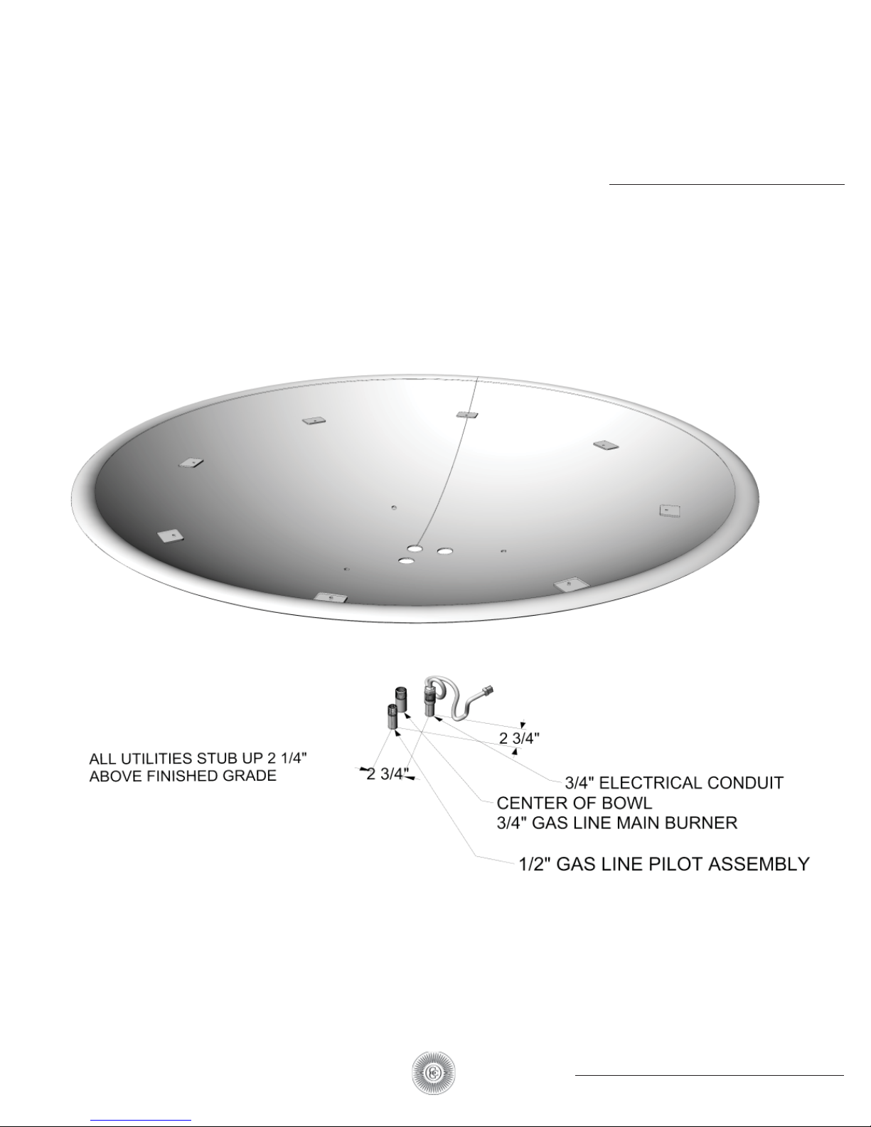
HOT SURFACE IGNITION PILOT LIGHT
PIPING PREP.
PART COMPONENTS
Pipe placement
Note: distances and heights
for each utility.
11
54 - 68 LL and NL ELECTRONIC IGNITION FIREBOWL
Page 12
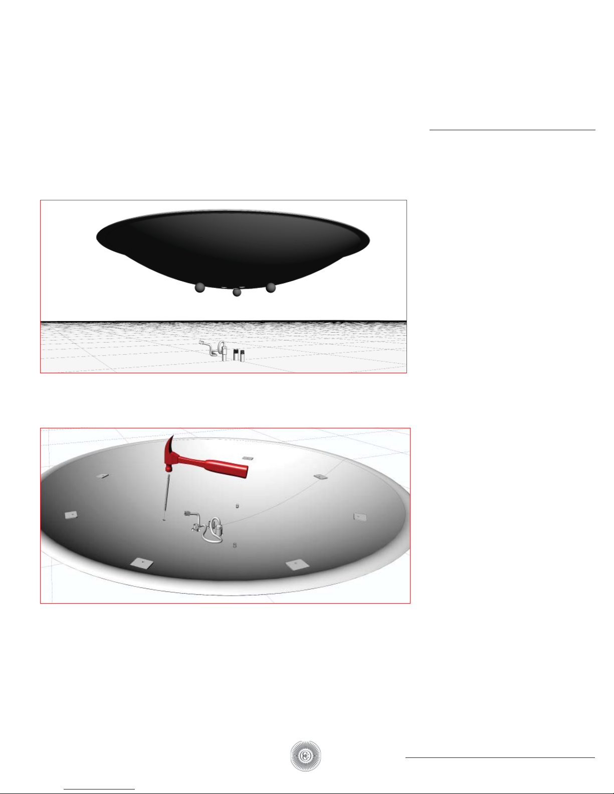
HOT SURFACE IGNITION PILOT LIGHT
PLACING AND
INSTALLING
BOWL
Placing the bowl over piping.
Installing Bowl
You’ll need to have a hammer, a socket wrench
and a 8” x 3/8” Expansion-Anchor-Bolt
Drill 3/8” hole 5 1/2” deep in a stable mount- ing platform: recommended a 20” diameter sonotube
concrete footing. Do this by drilling through the feet of the bowl.
Hammer Expansion-AnchorBolt into the hole. The bolt
should stick out into the bowl
with room for a washer and nut.
12
54 - 68 LL and NL ELECTRONIC IGNITION FIREBOWL
Page 13
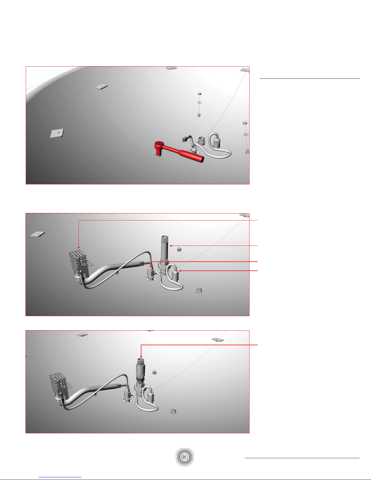
HOT SURFACE IGNITION PILOT LIGHT
INSTALLING
BOWL
Installing Bowl
Fasten nut with a ratchet until it fits
tight.
Connect Gas and Electric
NATURAL GAS (NG) SETUP
1. Pilot assembly includes Pilot Light, Hot Surface Ignitor
(Glow Plug), and Thermocouple
2. Gas line to main burner
(3/4” x 4-1/2” nipple and 3/4“ union)
3. Gas line to pilot (1/4” flare)
4. Electrical
Connect Gas and Electric
PROPANE GAS (LP) SETUP
1. 3/4” close nipple, 3/4” coupling,
3/4” airmixer, 3/4” union
13
54 - 68 LL and NL ELECTRONIC IGNITION FIREBOWL
Page 14
HOT SURFACE IGNITION PILOT LIGHT
INSTALLING
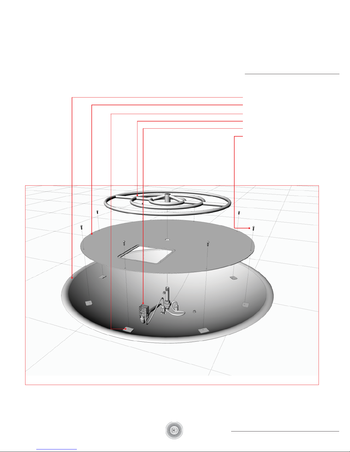
BURNER
1. 54LL firebowl
2. Heat shield
3. Heat shield mounting tab
4. Burner
5. Pilot assembly
6. 1/4-28 screw (8x)
14
54 - 68 LL and NL ELECTRONIC IGNITION FIREBOWL
Page 15
HOT SURFACE IGNITION PILOT LIGHT
INSTALLING
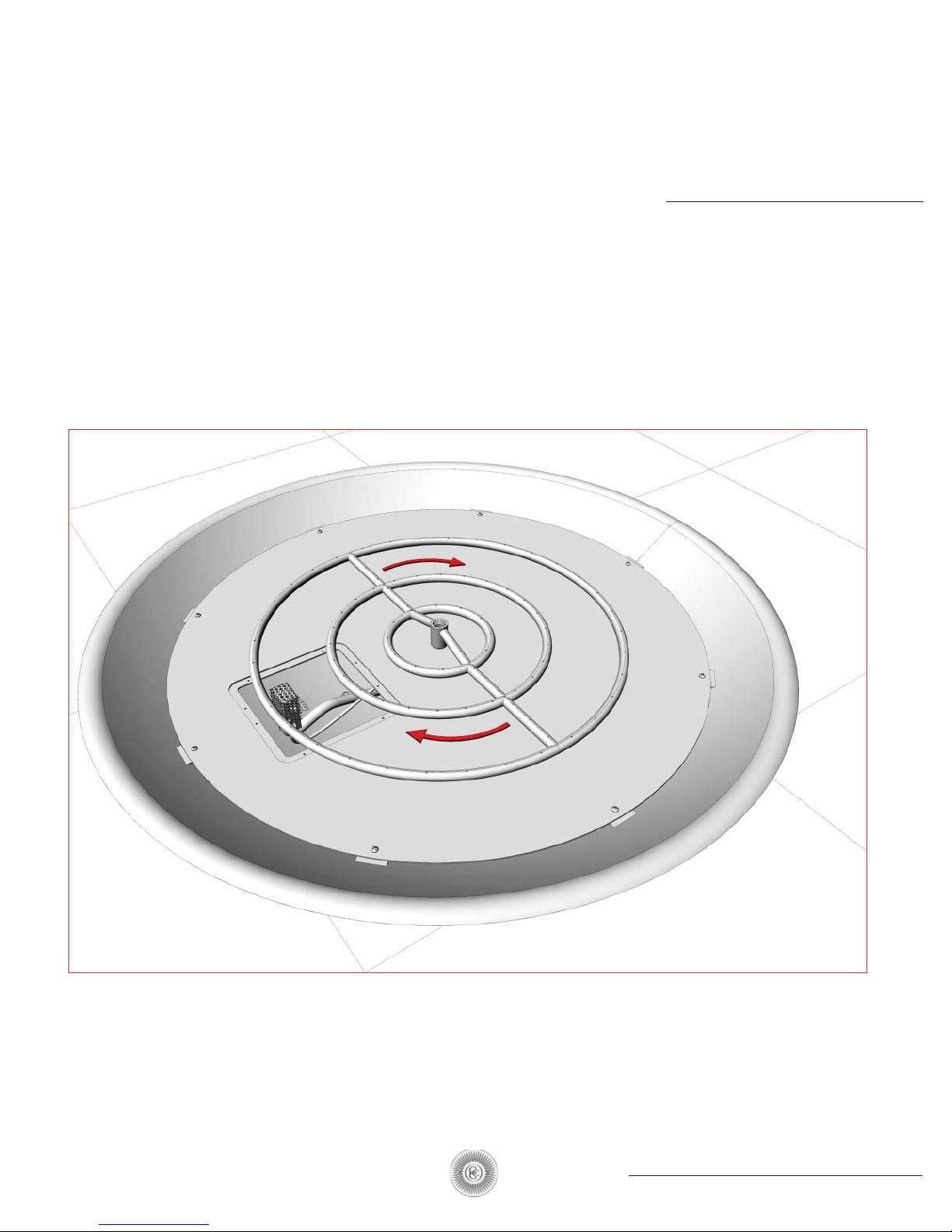
BURNER
Once you have the heat shield secured to the bowl, spin the burnerin a clockwise position until snug.
15
54 - 68 LL and NL ELECTRONIC IGNITION FIREBOWL
Page 16
HOT SURFACE IGNITION PILOT LIGHT
PLACE PILOT
ASSEMBLY
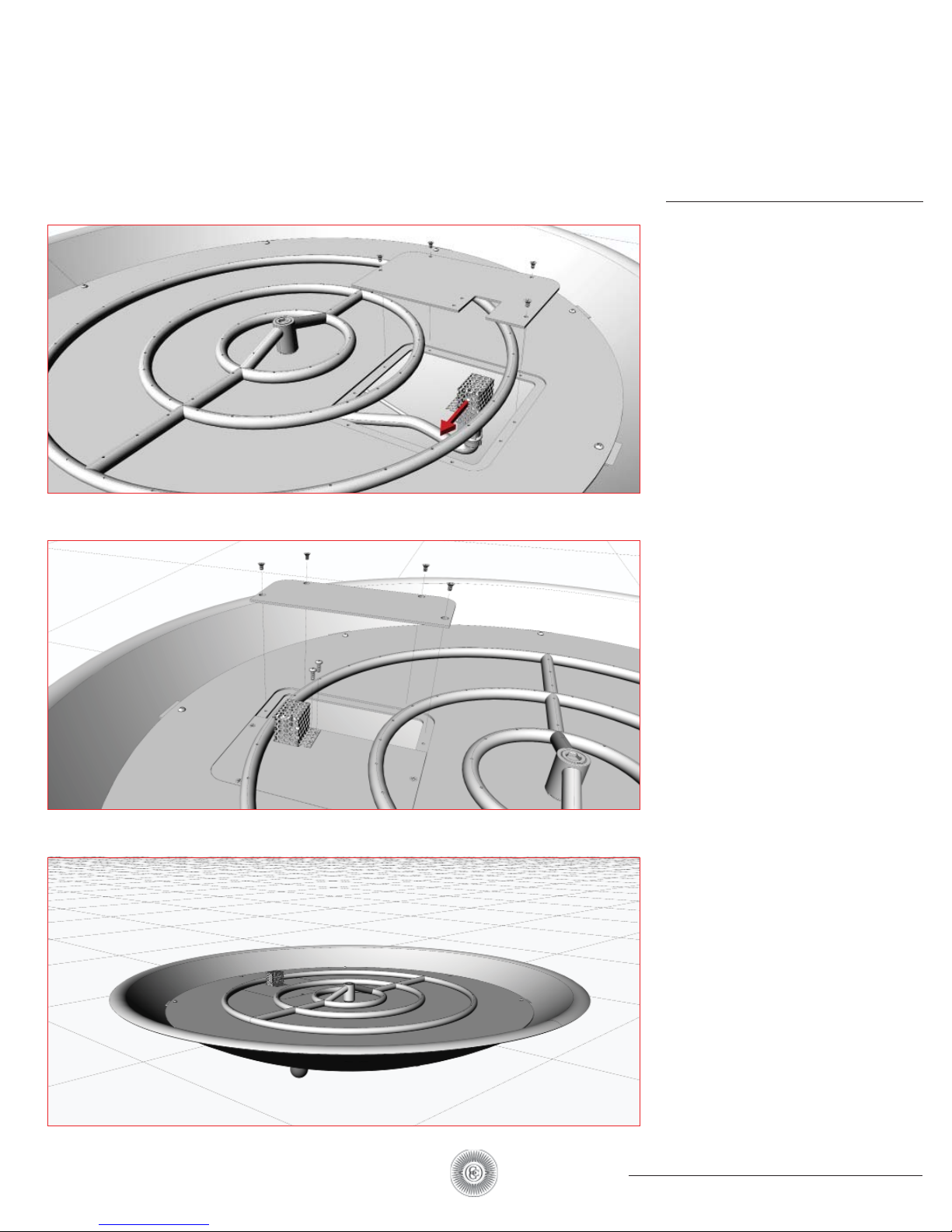
Place the pilot assembly place the first half of the access
panel onto the heat shield
and secure with screws. The
pilot assembly will need to
be pushed to the side in
order to get the panel in place.
Secure the pilot with screws.
Place the final half of the
access panel and
secure with screws.
Final assembly
16
54 - 68 LL and NL ELECTRONIC IGNITION FIREBOWL
Page 17
HOT SURFACE IGNITION PILOT LIGHT
FIREBOWL
IGNITION
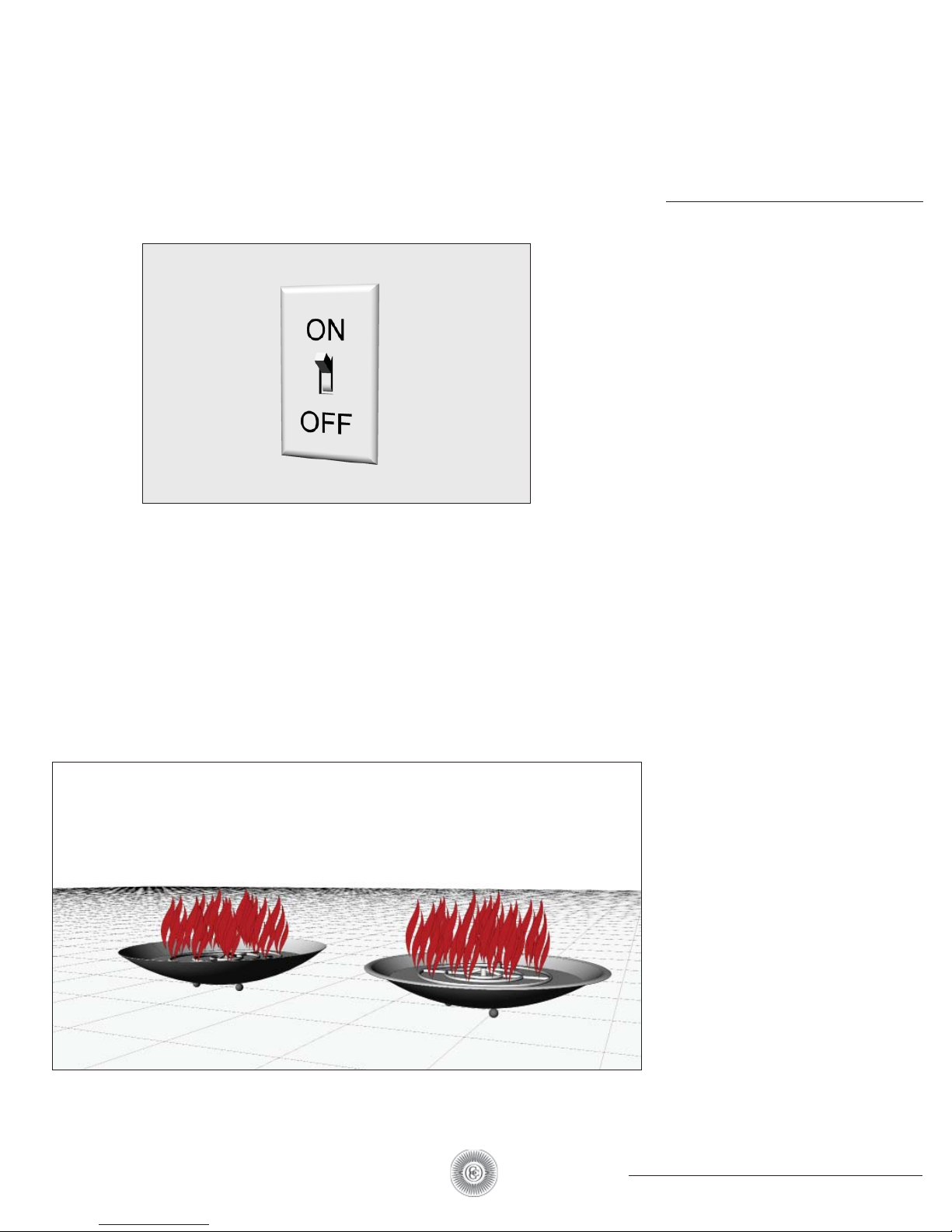
TO LIGHT APPLIANCE
Before operating appliance ensure the
plain view gas shut-off valve is open.
A.
Prior to turning appliance on
- Visually inspect appliance to ensure debris
such as leaves or other combustible material
has not collected inside the appliance which
could burn and emit embers once the appliance is turned on.
- Ensure any person standing close to the
appliance is aware you will be turning the
appliance on prior to actually turning it on.
B.
Turn appliance on by turning on the electrical
device used to power the appliance.
SUCCESSFUL IGNITION
To adjust flame height to preference, use the
plain view shut off valve to raise and lower
intensity of flame.
SEQUENCE OF OPERATION DURING IGNITION
- Power is applied
- Hot surface igniter (glow plug) becomes hot
and pilot gas valve opens.
- Within 10 seconds of power application
pilot flame should be visible (at night only).
- Within 10 seconds of pilot flame ignition,
burner element will ignite.
IF MAIN BURNER DOES NOT LIGHT, OR YOU
SMELL OR HEAR GAS, IMMEDIATELY TURN
PLAIN VIEW GAS VALVE TO OFF POSITION.
17
54 - 68 LL and NL ELECTRONIC IGNITION FIREBOWL
Page 18
HOT SURFACE IGNITION PILOT LIGHT
FIREBOWL
SHUT-OFF
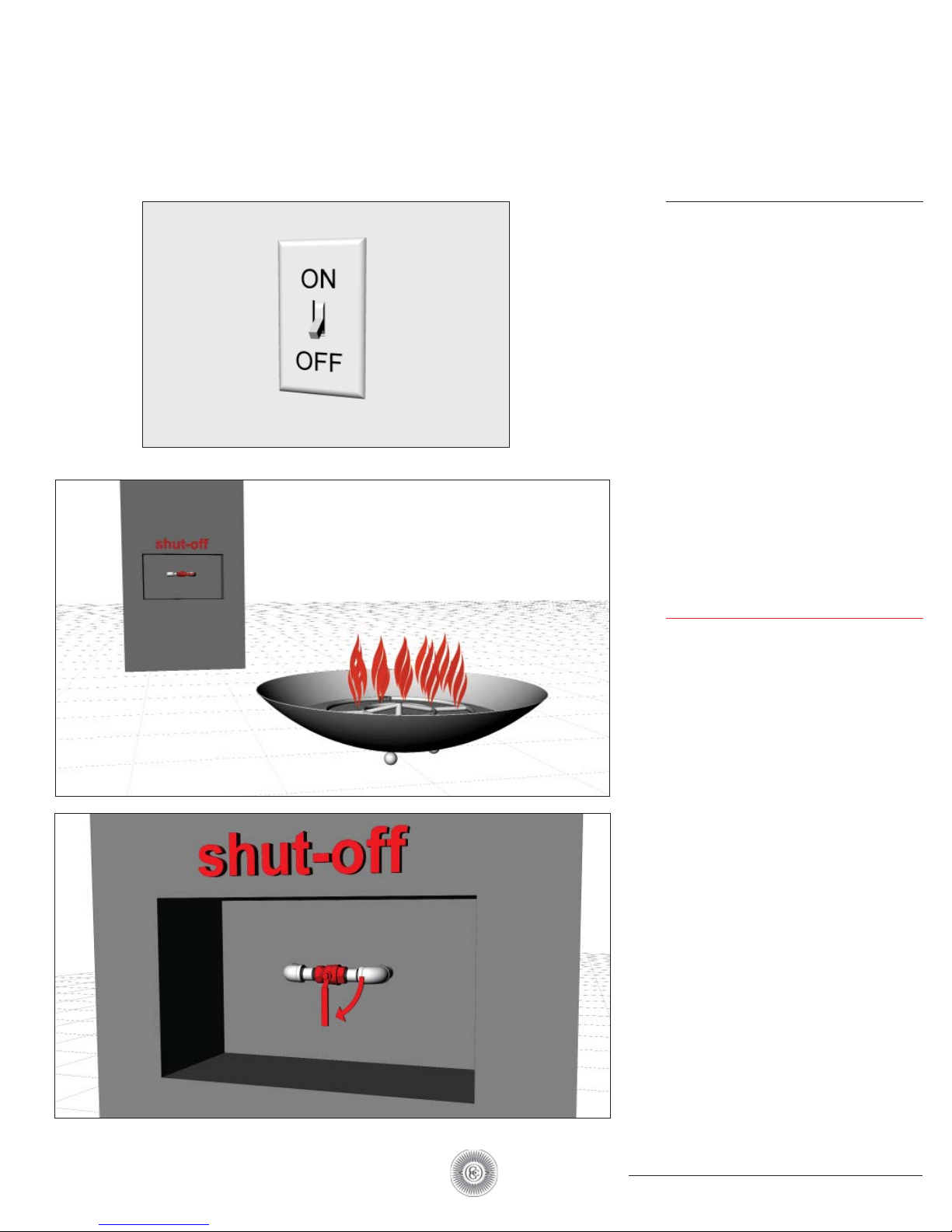
TO PUT BURNER OUT
Turn appliance off by turning off the
Electrical device used to power the
appliance.
IF MAIN BURNER DOES NOT LIGHT, OR YOU
SMELL OR HEAR GAS, IMMEDIATELY TURN
PLAIN VIEW GAS VALVE TO OFF POSITION.
EMERGENCY/
SHUT-OFF
PLAIN VIEW SHUT-OFF
TO PUT BURNER OUT
In the event of a uncontrolled fire,
always be aware of where the emergency
shut-off valve is located.
18
54 - 68 LL and NL ELECTRONIC IGNITION FIREBOWL
Page 19

HOT SURFACE IGNITION PILOT LIGHT
TROUBLESHOOTING
?
I installed the Electronic Ignition System, turned it on and nothing happened.
When this occurs it is usually due to an electrical wiring / power issue. Check all your
electrical connections thoroughly to ensure all wires at the transformer and inside the appliance are connected properly. If it appears all wiring is connected properly, disconnect the wires at the appliance, attach a Multimeter to the wires to confirm a minimum
of 24 volts when the appliance is turned on. If you determine that you do not have a minimum of 24 volts at the appliance conduct
the same test at the transformer to ensure the transformer is in fact producing a minimum of 24 volts. If you do have a
minimum of 24 volts at the appliance contact us for further assistance.
I installed the Electronic Ignition System, turned it on and I can see the glow plug glowing
orange and I can hear gas flowing but it will not ignite.
There are two possible causes to this problem; Air in the Gas Line or not enough Electrical Current to the appliance.
Air in the Gas Line - If a new gas line was installed and the air was never purged from it prior to installing the Electronic Ignition
System then it may take several times of turning the appliance on and off before the air is purged from the gas line. Here is how our
system works; after you turn it on the glow plug will come on first followed by the Pilot Gas Valve opening 4 seconds later. For the
next 180 seconds (3 minutes) the glow plug will cycle on and off every 30 seconds while the Pilot Gas Valve will remain on the entire
time. Therefore if you are attempting to purge air from the gas line, turn the system on and leave it on for approximately 3 minutes.
Then turn it off and then back on (no need to wait to turn it back on). Let the system run for another 3 minutes. Usually when
purging air from a new gas line you will need to cycle the power several times as described above
before gas begins to flow. If at any point you smell gas but still don’t have ignition, attempt to light the Pilot flame with a handheld
lighter. If the flame ignites when you light it by hand, go to the section below, “Electrical Current”.
Electrical Current - If you have determined that air in the gas line is not the problem then most likely the failure to ignite is due to
the fact the glow plug is not getting hot enough to ignite the gas. The reason a glow plug will not get hot enough is due to the
fact it is not getting enough ‘amps’. Often times when troubleshooting electricians will check the electrical power and when they
see they have a minimum of 24 volts they think everything is fine electrically so there must be a problem with the Electronic Ignition
System. The problem is not due to the volts but rather the amps. The number of amps reaching the appliance is heavily dependent
on the gauge wire used between the transformer and the appliance. Our Install Instructions require no less than 12 gauge wire be
run for all appliances. Often times we learn that in many cases less than 12 gauge wire has
been used and herein lies the cause of the problem. Here is how you check to determine if enough Electrical Current (amps) are
getting to the appliance:
1. CAUTION: TURN OFF THE GAS SUPPLY PRIOR TO THE NEXT STEP.
2. Using a clamp on amp meter, clamp the amp meter around one of the wires providing power to the Electronic Ignition System.
3. Turn the appliance on.
4. The amps you should see will range between 1.4 to 1.6 amps initially. Four seconds after being turned on the amps will jump to
approximately 2.0 amps.
If you do not see the amps listed above AND the wire gauge used was less than 12 gauge wire – change the wiring.
I turned the appliance off but I still see small flames emanating from the appliance.
Turn the appliance on, let the main burner light and then turn it off again – do this several times. Small pieces of debris from the
gas line can get caught in the main or pilot valve thereby preventing it from closing all the way. This will sometimes happen with a
new gas line. By cycling power you can often times dislodge the debris. If cycling power does not rectify the problem, turn the gas
off using the manual gas shutoff and contact us for further assistance.
19
54 - 68 LL and NL ELECTRONIC IGNITION FIREBOWL
Page 20
HOT SURFACE IGNITION PILOT LIGHT
ROCKS
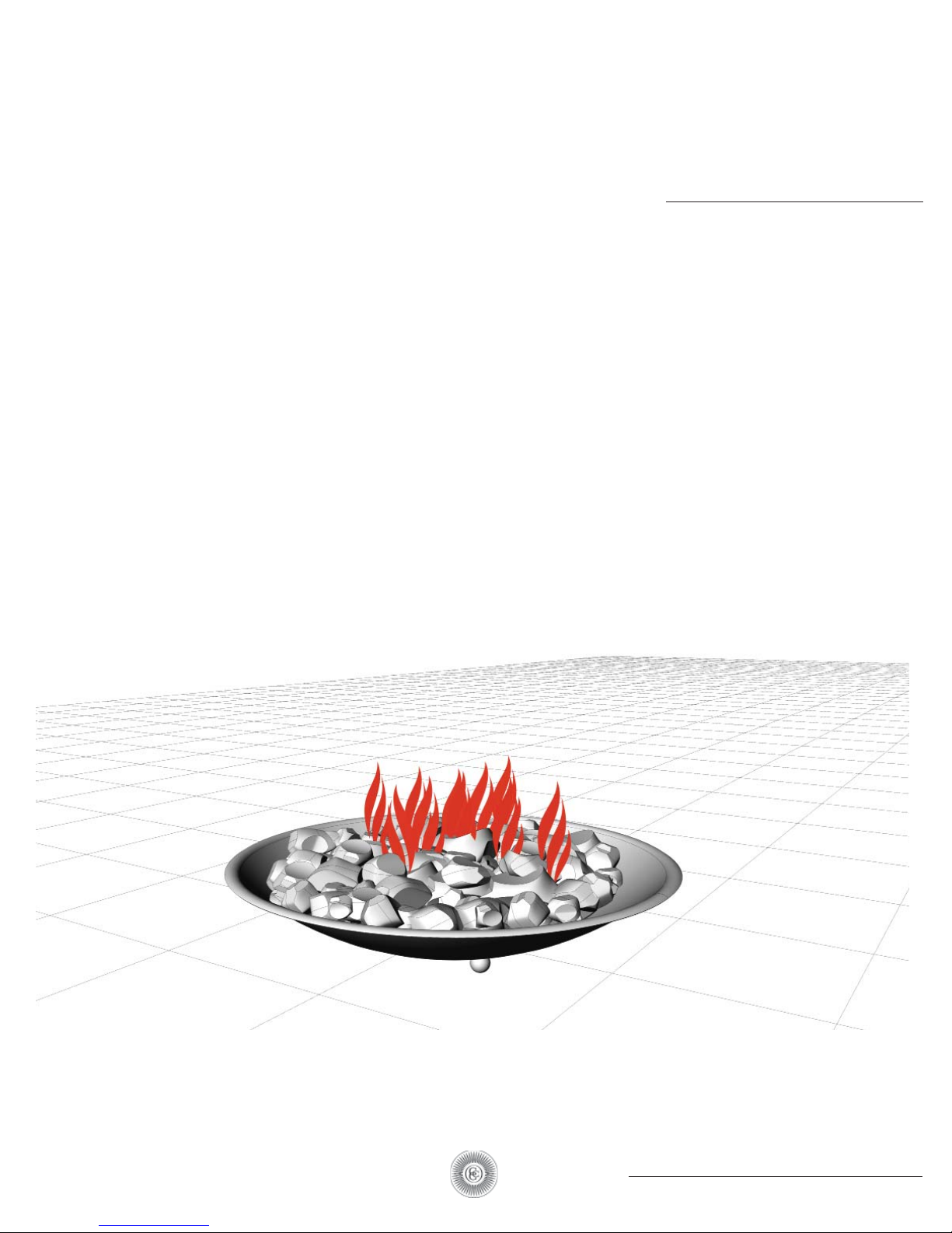
LAVA ROCK ONLY
Lava rocks are the recommended rock for
use in the Firebowl. Lava rock is best suited
because it was made by heat and therefore
does not react when used in a high heat
environment; it is also light weight and
readily available.
Lava rocks come in all sizes, from pebbles to
boulders. It is important to always use sizes
that range from 2” diameter and smaller.
You will need approximately 100 to 200lbs
for the firebowls.
Please contact the following website to
order lava rocks if you are unable to find
any at your local garden supply store:
http://www.fountainsnslate.com/
1-800-643-5804 or 1-386-586-4 062
WARNING: Other rocks may contain water,
and when heated will split, crack or burst
and are therefore to be used at your own
risk and not recommended.
20
54 - 68 LL and NL ELECTRONIC IGNITION FIREBOWL
Page 21
HOT SURFACE IGNITION PILOT LIGHT
MAINTENANCE
MAINTENANCE
Properly maintained, your decorative gas appliance will provide years of useful service. A
regular routine maintenance program such as
the program outlined below should be established and followed. It is further recommended to follow the maintenance procedures on
safety valves and other accessory equipment
according to the manufacturers instructions.
It is recommended to have at least one annual
inspection performed by a certified gas technician.
Routine Preventive Maintenance:
Have the appliance serviced and leak checked
A.
annually by a qualified service technician.
Keep the area inside and around the ap-
B.
pliance and base free of debris, foreign
matter, or obstruction. Regularly remove all
broken rock chips, leaves, branches, grass, etc
from fire feature on a daily or weekly basis.
C.
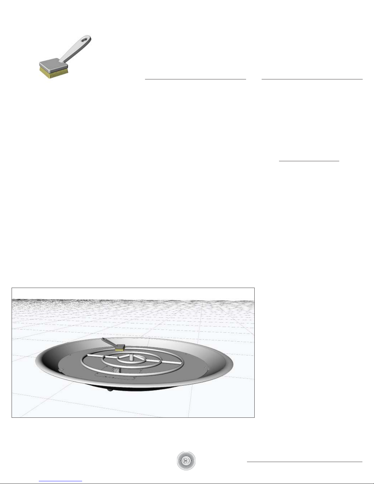
Clean any corrosion or scale off burner, control panel, and venturi with a wire brush.
Make sure that venturi remains set in position.
See page 12.
D.
Visually inspect the burner regularly both
while firing and while turned off. Replace any
c or ro de d p ar t s.
E.
Visually inspect pilot while main burner is on
and while main burner is off. Replace any corroded parts. Be certain that pilot position is
correct and that pilot reliably and accurately
ignites main burner.
Use a tooth pick or thin wire to poke out any
F.
clog or obstruction from the small holes in the
burner, only when the burner is off.
G.
Check to be certain that the area the gas
equipment operates in is free of obstruction.
Remember, that for proper combustion, proper operation, and proper ventilation, flow of
air around your gas equipment must be unobstructed. Never store combustible materials
or flammable liquids near any gas equipment.
When burners are not in use for a long time,
H.
or are used only seasonally, care should be
taken to wire brush scale off burners and
inside venturi. An air compressor can be
used to blow out cobwebs or nests which may
clog orifices.
*If any unusual behavior of the gas equipment is noted during inspection, shut the
burner off until qualified service assistance
can be obtained.
*For your safety, all repairs on the burner system should be performed by qualified service
personnel only as it involves disconnecting gas
supply and performing leak testing.
54 - 68 LL and NL ELECTRONIC IGNITION FIREBOWL
21
Page 22

 Loading...