

Collins MP 200, MP 600, MP 1000, MP 1200 Owner's Manual
Features:
• flexibles Anschlusskonzept mit symmetrischen XLR-Eingängen und parallelen Klinkenbuchsen
• Anschluss der Lautsprecherboxen via Speakonkabel
• zusätzliche Lautsprecher-Schraubklemmen („Banana-Jacks“) ermöglichen problemlose Rack-Installation
• zwei Betriebsarten: Neben dem herkömmlichen Stereobetrieb lassen sich beide Endstufenkanäle brücken
(„Bridged“-Betrieb), so dass die Gesamtleistung an einer Klemme addiert zur Verfügung steht.
• pro Kanal fünfteilige Signal/Clip-Leuchtdiodenanzeige
• pro Kanal Level-Regler zur Pegelanpassung
• Ground Lift-Schalter zur Vermeidung von Brummschleifen
• Lüfterkühlung sorgt für optimale Temperaturbedingungen auch bei hoher Belastung
BEDIENUNGSANLEITUNG
Collins Professional Power Amplifiers
MP 200 • MP 600 • MP 1000 • MP 1200
Inhalt:
1. Bedienelemente auf der Frontplatte
2. Bedienelemente auf der Rückseite
3. Inbetriebnahme
4. Sicherheitshinweise
5. Technische Daten
Content:
1. Control elements on the front panel
2. Control elements on the back panel
3. Start-Up
4. Safety instructions
5. Specification
OWNERS MANUAL
Collins Professional Power Amplifiers
MP 200 • MP 600 • MP 1000 • MP 1200
Features:
• Flexible connections with symmetrical XLR inputs and parallel ¼“ jack inputs
• Connection of loudspeakers via speaker inputs
• Additional loudspeaker terminals („banana jacks“) allow easy rack installation
• Two operating modes: besides the common stereo mode both amplifier channels can
be bridged to delivery the total accumulated power into one single speaker output.
• Five signal/clip-LED’s per channel
• Level control per channel
• Ground Lift switch to avoid ground loops
• Fan cooling system for optimum temperature conditions even at highest Levels
Bedienungsanleitung.pmd 18.09.2002, 14:261
Schwarz
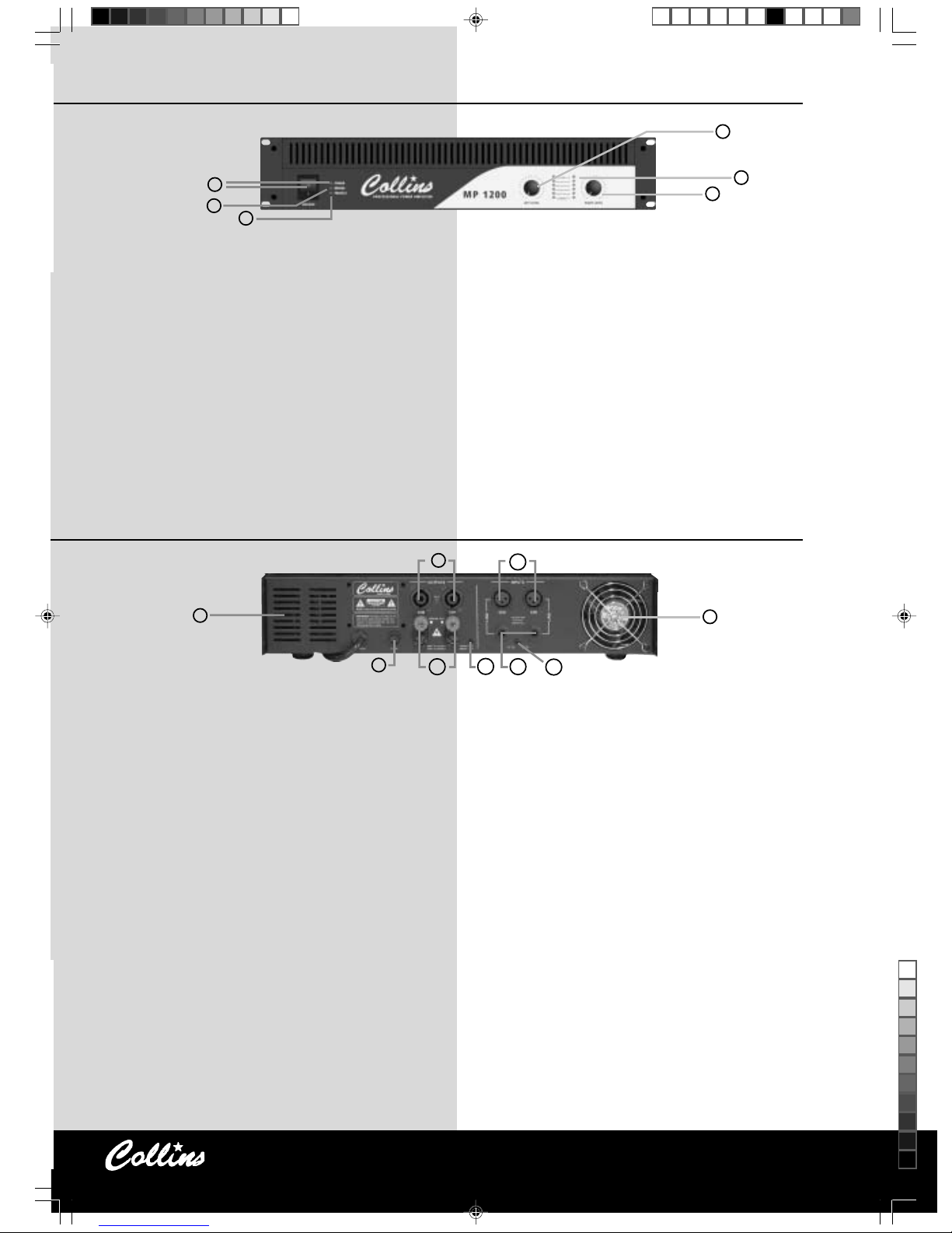
1. Bedienelemente auf der Frontplatte 1. Control elements on the front panel
1. Netzschalter und „Power“-LED: Um das Gerät einzuschalten, stecken Sie das
Netzkabel in eine Schuko-Steckdose und bringen Sie den Netzschalter in Position
»1«. Daraufhin leuchtet die „Power“-LED und zeigt die Betriebsbereitschaft Ihrer
Collins-Endstufe an.
2. „Bridge“-LED: Diese LED signalisiert, dass die Endstufe mit dem „Stereo/Bridge“Schalter (11) in den Brückenbetrieb geschaltet ist.
3. „Protect“-LED: Die „Protect“-Anzeige leuchtet auf, sobald die interne Schutzschaltung infolge Überlastung durch Übertemperatur anspricht. Zum Schutz der
angeschlossenen Lautsprecher ist die Schutzschaltung auch während des Ein- und
Ausschaltens aktiv.
4. „Left Level“-Regler: Mit diesem Regler können Sie den an der XLR- und
Klinkenbuchse des linken Kanals anliegenden Eingangspegel dämpfen und so die
Wiedergabelautstärke bestimmen. Steht der Regler am rechten Anschlag
(„vollständig offen“), verarbeitet die Endstufe exakt den anliegenden und an
Ihrem Mischpult angezeigten Ausgangspegel.
5. „Right Level“-Regler: Mit diesem Regler können Sie den an der XLR- und
Klinkenbuchse des rechten Kanals anliegenden Eingangspegel dämpfen und so die
Wiedergabelautstärke bestimmen. Steht der Regler am rechten Anschlag
(„vollständig offen“), verarbeitet die Endstufe exakt den anliegenden und an
Ihrem Mischpult angezeigten Ausgangspegel.
6. LED-Pegelanzeigen: Diese LED-Ketten informieren Sie über die Aussteuerungszustände beider Kanäle und auch über die Auslastung Ihrer Collins-Endstufe.
1. Power On/Off switch and „Power“-LED: to switch on the amplifier plug in the
power cord into an appropriate power outlet (230V, 50Hz) and bring the power
switch into position »1«. The Power-LED is lit and shows that your Collins
Professional Power Amplifier is ready to work.
2. „Bridge“-LED: this LED indicates that the amplifier is set to run in bridge mode,
that is activated with the „Stereo/Bridge“-switch (11) on the back of the amplifier.
3. „Protect“-LED: the „Protect“-LED lits as soon as the internal protection circuitry
has been triggered due an overload or overheating. To protect the connected
loudspeakers the circuitry is also activated while the amplifier is switched on or
off.
4. „Left Level“-potentiometer: this control attenuates the input signal (connected to
the XLR- or the jack input) of the left channel and allows you therefore to control
the volume. Turned fully clockwise the amplifier gets exactly the level indicated
from the connected signal source (e.g. a mixer).
5. „Right Level“-potentiometer: this control attenuates the input signal (connected
to the XLR- or the jack input) of the right channel and allows you therefore to
control the volume. Turned fully clockwise the amplifier gets exactly the level
indicated from the connected signal source (e.g. a mixer).
6. LED level indicators : these LED meters indicate the current levels of the left and
right input channels as well as the remaining headroom of your Collins
Professional Power Amplifier.
2. Bedienelemente auf der Rückseite 2. Control elements on the back panel
7. Lüfteröffnungen: Hier entweicht die zur Kühlung der Endstufe erforderliche Luft.
Stellen Sie sicher, dass diese Öffnungen während des Betriebs nicht verdeckt
werden.
8. Netzsicherung: Ersetzen Sie im Bedarfsfall die Sicherung nur durch einen
identischen Typ mit identischer Belastbarkeit. Nachdem Sie das Gerät vom
Stromnetz getrennt haben, können Sie den Sicherungseinsatz mit Hilfe eines
Schraubendrehers aus der Fassung entnehmen. Vorsicht: Höhere Absicherung
oder gar das Überbrücken kann im Falle eines Defekts zu schweren
Brandschäden führen!
9. Speaker-Buchsen: Hier schließen Sie Ihre Lautsprecherboxen an. Sie benötigen
dazu zweiadrige Lautsprecherkabel mit Speakon®-Steckern, die durchgehend auf
den Kontakten »1+« und »1-« belegt sind. Vieradrige Lautsprecherkabel mit NL-4Speakon® funktionieren ebenso. Beachten Sie stets die Mindestimpedanzen und
unterschreiten Sie sie (z.B. durch Parallelschaltung weiterer Boxen) nicht.
Collins-Endstufen arbeiten an pro Kanal vier Ohm Lautsprecherlast optimal.
Unterschreitung kann zu Überlastung und zum Ansprechen der Schutzschaltung
führen.
10. Schraubklemmen: Die Schraubklemmen sind den Speaker-Lautsprecherbuchsen
parallel geschaltet. Wenn Sie die Collins-Endstufe in ein Rack mit einem extra
Steckpanel oder einen Installationsschrank einbauen, können Sie hier die
Lautsprecherleitungen direkt anklemmen und die Speakonstecker einsparen.
Halten Sie dabei aber unbedingt die Polarität ein, indem Sie die Pluspole der
Boxen stets an die roten, die Minuspole dagegen immer an die schwarzen
Klemmen anschließen.
11. „Stereo/Bridge“-Schalter: Dieser Schalter stellt den Betriebsmodus der Endstufe ein.
Die Stellung „Stereo“ repräsentiert dabei den Normalfall, denn damit können Sie ein
Stereosignal oder auch zwei voneinander unabhängige Monosignale verstärken und
über zwei Lautsprecherboxen wiedergeben. In „Bridge“-Position hingegen werden
beide Endstufenkanäle quasi „huckepack“ zusammengekoppelt, so dass die
Ausgangsleistungen beider Kanäle addiert zur Verfügung stehen. Dieser Zustand
wird durch die „Bridge“-LED (2) auf der Frontplatte angezeigt. Allerdings können Sie
jetzt nur noch ein am Eingang des linken Kanals (CH L) anliegendes Monosignal
verstärken. Dieses führen Sie der Lautsprecherbox zu, indem Sie die beiden Leiter des
Boxenkabels an die beiden roten Schraubklemmen anschließen. Beachten Sie auch
hier die am Gerät aufgedruckte Polarität und die Impedanz der Box. Im Vergleich zu
vorher muss diese im Brückenbetrieb statt vier Ohm nun acht Ohm betragen.
12. XLR-Eingänge: Über die XLR-Eingänge können Sie die beiden Eingangssignale in
dreipoliger symmetrischer Form in Ihre Collins-Endstufe einspeisen. Die Belegung der
7. Ventilation grills: the ventilation grills allow the amplifier to exhaust its heat.
Make sure that the grills are not covered during operation.
8. Fuse: In case of a failure of the fuse replace it only with a fuse of identical type
and identical specification. After disconnecting the amplifier from the power
outlet you can remove the fuse holder using a screw driver. Attention: the
application of higher rated fuses or bridging can cause severe damage (fire!) in
case of an amplifier failure!
9. Speaker connectors: plug in your loudspeaker here. You need a speaker cable with
two wires and a Speakon® connector. The active contacts are »1+« and »1-«.
Please watch the minimum impedance and do not connect speaker loads below
the rated values (e.g. caused by multiple loudspeakers connected in parallel).
Collins Professional Power Amplifiers work best at four ohms load impedance per
channel. A load below this rating can cause overload and triggers the protection
circuitry.
10. Screw Terminals: the screw terminals are in parallel with the speaker connectors
and allow you to save the Speakon® connectors when you install the Collins
Professional Power Amplifier with a separate patch panel or in an installation rack.
Please pay attention to correct polarity to make sure your PA system runs properly.
Switched polarities can cause severe influence on the frequency response of your
PA system.
11. „Stereo/Bridge“-switch: controls the operating mode of the amplifier. The position
„Stereo“ is meant for the common two channel mode that allows you to amplify a
stereo signal or two independent mono signals reproducing the signals via two
loudspeaker cabinets. In „Bridge“ position both amplifier channels will be
coupled, so that the total power is added into one single output. This operating
mode is indicated by the lit „Bridge“-LED (2) on the front panel. This mode
converts the device into a single channel amplifier, that only amplifies the signal of
the left input channel. The loudspeaker cabinet has to be connected by using the
two red screw terminals on the amplifier back panel. Please pay attention to
correct polarity and impedance. Important note: the minimum load
impedance in bridge mode is eight ohms instead of four ohms in
stereo mode!
12. XLR inputs: the XLR inputs allow the connection of symmetrical three pole input
signals to your Collins Professional Power Amplifier. The pin out of the XLR
connectors follows the international AES 14 standard. The „hot“ signal appears on
pin 2, the inverted „cold“ signal on pin 3. Pin 1 of the XLR input contacts the
signal ground which is connected to the shield of the cable.
13. Ground lift switch: the ground lift switch disconnects the signal ground from the
1
2
3
4
6
5
7
7
8
9
10
11
12
13
14
Bedienungsanleitung.pmd 18.09.2002, 13:302
Schwarz
 Loading...