

Collins KWM-2, KWM-2A Instruction Book
Cedar Rapids Division I Collins Radio Company, Cedar Rapids, Iowa
Collins Amateur Equipment Guarantee
The Collins Amateur Equipment described herein
is
sold
under the following guarantee:
Collins agrees to repair or replace, without charge,
any equipment, parts, or accessories which aredefective as
to
work mans hi^
or materials and which are returned to
Collins at its
-factory or
its
designated Service Agency,
transportation prepaired, provided:
(a) Buyer presents properly executed Warranty Verifi-
cation Certificate.
@)
Notice of the claimed defect is given Collins or
an authorized Service Agency, or an authorized
Distributor. in ,writing. within
180
days from the
date of purchase and goods are
returnedinaccord-
ance with Collins instructions.
(c) Equipment. accessories, tubes, and batteries not
manufactured by Collins or from Collins designs
are subject
to
only such adjustments as Collins
may obtain from the supplier thereof.
(d) Any failure due to use of equipment for purposes
other than those contemplated in normal amateur
operations or in violation of Collins applicable
Instruction Book shall not be deemed a defect
within the meaning of these provisions.
This Warranty is void with respect to equipment which
is
altered, modified or repaired by other than Collins or
Collins Authorized Service Agencies. However, alteration
or modification in accordance with Collins Service Bulletins
shall not affect this Warranty.
Collins reserves the right to make any change in de-
sign or to make additions
to,or improvements in, Collins
products without imposing any obligations upon Collins to
install them in previously manufactured Collins products.
No other warranties, expressed or implied, shall be
applicable to said equipment, and the foregoing shall constitute the Buyer's sole right and remedy under the agreements contained in these paragraphs. In no event shall
Collins have any liability for consequential damages, or for
loss, damage or expense directly or indirectly arisingfrom
the use of the products, or any inability to use them either
separately or in combination with other equipment or
materials or from any other cause.
NOTICE: With each equipment or set of equipments pur-
chased, the distributor should furnish a Warranty
Verification Certificate. It
is
necessary that this
certificate accompany the equipment when it
is
returned for warranty repairs. Be sure that you
get it from your distributor.
Warranty Repairs
On the opposite page are listed the Service Agencies ADDRESS:
INFORMATION NEEDED:
authorized to perform warranty repair on Collins Amateur
Equipments.
If
you shouldwish to returnmaterial or equipment direct
to
Collins under the guarantee, you should notify Collins,
1
giving full particulars including the details listed below,
insofar as applicable.
If
the item
is
thought
to
be defective.
such notice must give full information
as
tonature of defect
and identification (including part number if possible) of
part considered dqfective. Upon receipt of such notice,
Collins
will
promptly advise you respecting the return.
Failure to secure our advice prior to the forwarding of the
goods or failure
to
provide full particulars may cause
unnecessary delay in handling of your returned merchandise.
Collins Radio Company (A) Type number, name and
Amateur Product Office serial number of equipment
Cedar Rapids, Iowa (B) Date of delivery of
1
equipment
L/
(C)
Date placed in service
(D) Number of hours of service
(E) Nature of trouble
(F)
Cause of trouble if known
(G)
Name of distributor from
whom the equipment was
purchased.
Equipment returned
to
the Service Agency or Collins for
warranty repair
must
be accompanied with the Warranty
Verification Certificate.
Out-of-warranty Repair, Modifications, Addition of
Accessories, Alignment, etc.:
For information on service of this type write
to
the HOW TO ORDER REPLACEMENT PARTS:
address shown below.
If
you wish to return your equipment
for repairs, etc., without prior correspondence, be sure
to include the following information attached
to
the equip-
ment inside the packing carton:
(1)
Complete instructions detailing work to be
performed.
(2)
your return address.
(3)
Method of shipment by which the equipment should
be returned.
(4)
Special instructions.
DIRECT YOUR CORRESPONDENCE
TO:
Collins Radio Company
Service Repair Department
Third Street Building
Cedar Rapids, Iowa
When ordering replacement parts, you should direct
your order to. one of the listed Collins distributors.
Please furnish the following information insofar as
applicable:
INFORMATION NEEDED:
(A) Quantity required
(B) Collins part number
(9
or
10
digit number) and
description
(C) Item or symbol number obtained from parts list
or schematic
(D) Collins type number, name and serial number of
principal equipment
-
(E) Unit subassembly number (where applicable)
u
NOTE: See Distributor List.
1
August
1962

COLLINS AUTHORIZED AMATEUR DISTRIBUTORS AND SERVICE AGENCIES
ALABAMA
COLORAW
ILLINOIS
*Two-Way Radio Engineers. Inc.
109-115 Ward Street
Boston
Rep:
Shermm M. Wow
Ack Radio Supply Company
3101 4th Avenue South
Birmingham 5
Phone:
FAirfax 2-0588
Rep: E. C. Alkersm~
SEE ALSO: Atlanta, Georgia
Radio Products Sales Co.
1237
-
16th St.
Denver 2
Phone:
CHerry 4-6591
Rep:
Waltev ~ettles/l~illord Wrighl
Allied Radlo Corp.
100 N. Western Avenue
Chicago 80
Phone:
HAymarket 1-6800
Rep: Jack
Schneider/Hal Eisenberg
MICHIGAN
*Communication Service Company
201 South Lincoln
Charlotte
Phone: 1770-W
Rep:
Bar1 Rypslra
CONNECTICUT
Klaus Radio & Electric Company
403 E. Lake St.
Peorla
Phone: RH 8-3401
Rep: Clifford M&s
*Beddow Engineering Services
2424 Tenth Avenue South
Birmingham
Phone:,
ALpine 1-7582
Rep:
D7.
C,
P.
Beddoto
Corky's 01 Hartford. Inc.
203 Ann Street
Hartford
Phone:
JAckson 1-1881
Rep: Edwmd C. Cedney
M. N. Wry & Co.
2040 Grand River Avenue W.
Detroit 26
Phone:
WOodward 3-2210
Rep: M. N. &y/Bill Mains
Newark Electronics Corporation
223 W. Madison Street
Chicago 6
Phone:
STate 2-2944
Rep: Les Wilkins/A. L. Pacher
ALASKA
Radio Shack Cow. of Connecticut
230 Crown Street
Yukon Radio Supply, Inc.
(P.O. Box 406)
645
1 Street
Anchorage
Rep: A.
E.
Peterson
New Haven 10
Phone:
Spruce 7-6871
Rep:
E.
G. Alberim
SEE ALSO: Boston, Massachusetts
'Huntress Electronics
93 Talcott Road
West Hartford 10
Phone:
ADams 6-0990
Rep: Bob Resconsin
Purchase Radio Supply
327 E. Hoover Avenue
Ann Arbor
INDIANA
Brown Electronics, Inc.
1032 Broadway
Fort Wayne
Phone:
ANUlony 3382
Rep: A. A.
Brm
Phone: Normandy 8-8696
8-8262
Rep: Roy
J.
Purchase
ARIZONA
Elliott Electronics. Inc.
418 N. 4th Avenue
Tucson
Phone:
MAin 4-2473
Rep: Jerry
Flewelling
Warren Radio Company
1710 South Westnedge
Kalamazoo
Phone: FIreside 2-5720
2-7121
Rep: Frank Smith
DELAWARE
Graham Electronics Supply. Inc.
122 S. Senate St.
Indianapolis 4
Phone:
MElmse 4-8487
Rep: IHCk S@gel/H. H. Thompson/
G. M. Graham
Willard S. Wllson. Inc.
403-405 Delaware Avenue
Wilmington 1
Phone:
OLympia 5-4321
Rep: Willard S.
Y1-
"Southwest Electronic Devices
(P.O. Box 3647)
140 S. 2nd Street
Phoenix
Phone:
Awine 2-1743
Rep: Herman A.
Middlelon
MINNESOTA
Radlo
Distributing
Co.. Inc.
(P.O. Box 1499)
I212 High St.
South Bend 15
Phone:
ATlantic 8-4665
Rep: William A. Ddson
Lew Bonn Company
1211
LaSalle Avenue
Minneapolis 3
Phone:
FEderal 9-6351
Rep: Bob
Woodrow/Don CiedJoe
ARKANSAS
Electronic Wholesalers. fnc.
2345 Sherman Ave. N.W.
Washington
1
Phone: Hudson 3-5200
Rep: Ray
Auey
Hoh
Lavender Radio & TV Supply Co.. Inc.
(P.O. Box
1168)
522 E. 4th Street
Texarkana
Phone: 2-4195
Rep:
Joe
M.
Lavender
**Electronic Center. Inc.
107 3rd Avenue N.
IOWA
Minneapolis 1
Phone:
FEdera1 8-8678
Rep: Ward Jensen
Bob and Jack's. Inc.
4507 Forest Avenue
Des Moines 11
Phone:
BLackburn 5-0873
Rep: Robert M. Euans/Jack Landis
**Amateur Radio Center. Inc.
2805-7 N.E. 2nd Avenue
Miami
Phone:
FRanklin 4-4101
Rep:
Wiley Cilkison
**Broad Radio
7231 Central Avenue
St. Petersburg 10
Phone: 72314
REP: Morton S. Brood
**Electronic Wholesalers, Inc.
61 N.E. 9th Street
Miami 32
Phone:
FRanklin 7-2511
Rep: Frank
Ganlx
Moory's Wholesale Radio & Apuliance
Co.
MISSISSIPPI
. .
12th & Jefferson
DeWitt
Phone: WHitnev 6-2820
Swan Distributing Company. Inc.
(P.O. Box 2698)
342 N.
Gallatin St.
Jackson
Phone:
FLeetwood 2-5516
Rep: Leo
A.
swmt.
JY.
Radlo Trade Supply Co.
1224 Grand Avenue
Des Molnes 9
Phone:
ATlantic 8-7237
Rep: Leo Vince Dauis
Rep: ~d
~oori
CALIFORNIA
Amrad Supply, Inc.
999 Howard Ave.
World Radio
Laboratories,
Inc.
3415-27 W. Broadway
Council
Bluffs
Phone: 32-81851
Rep: Ah McMilWLeo Meyewon/
C. H. Williams
MISSOURI
Burlingame
Phone:
DIamond 2-5757
Rep:
an
Rodriquez
Walter Ashe Radlo Company
1125 Pine Street
St. Louis
1
Phone: CHestnut 1-1125
'Communication Receiver Servlce
5016 Maplewood
Los ~ngiles 4
Phone:
HOLlywood 2-2429
Rep: CImles C. Messman
Electronic Wholesalers. Inc.
1301 Hibiscus Boulevard
Melbourne
Phone:
PArkway 3-1441
Rep: Fvank
Gdz
Grice ELectmnics. Inc.
(P.O. Box 1911)
300 E. Wright St.
Pensacola
Phone: HEmlock 3-4616
Rep:
F.
G. Cvice,
Jr.
**Kinkade Radio Supply, Inc.
1719 Grand Central Avenue
Tampa
Phone:
8-6043
Rep: E. T. Kinkade
KANSAS
Rep: Joe Nouak/Bill Dubord
Burstein-Applebee Co.
1012-1014
McGee Street
The Overton Electric Co., Inc.
522 Jackson Street
Topeka
Phone:
CEntral 3-1367
Rep:
S.
D. Thacher
ELmar Electronics
Kansas
City 6
Phone:
BAltimore 1-1155
Rep: R.
H.
Friesz/Bill Tqgan
140 11th Street at Madison
OakIand 7
Phone: TE 4-3311
(TWX-OA731
Henry Radio Company
211
Noh Main
Butler
Phone:
ORchard 9-3127
Rep: Bob
Henry/Helen DeArmond
Rep: Elvtn ~eige/~. L. ~hiroie
**Henry Radlo, Inc.
(P.O. Box 64398)
11240 W.
Olvmoic Blvd.
KENTUCKY
Radio-Electronic Equipment Co.
(P.O. Box 1212)
480 Skain Avenue
Lexington
Phone:
3-1577
Rep:
A.
A. AWaham
~os ~ngelei 64
Phone: GRanite 1-6701
Rep: Ted Henvy
Quement Industrial Electronics
(P .O. Box 527)
161 San Fernando
San Jose
Phone:
Cypress 4-0464
Rep:
Frank Qlemail
Radio Products Sales. Inc.
1501
S.
Hi11 Street
Los Angeles 15
Phone:
RIchmond 8-1271
Rep: Kaf Rmrsin
Valley Electronic Supply Co.
1302 W. Magnolia Blvd.
Burbank
Phone: Vlctoria 9-3944
Rep: Frank
EckevVBud Rand
MONTANA
Electric City Radio Supply
2815
-
10th Avenue South
Great Falls
Phone: GL 2-6236
Rep: Frank Anderson
WUISIANA
GEORGIA
**Radio Parts, Inc.
807 Howard Avenue
New Orleans 12
Phone:
JAckson 2-0217
Rep: rrvine
J.
~eui
Ack Radio Supply Co.
331 Luckie St. N.W.
Atlanta 13
Phone: JA
4-8477
Rep: T.
E.
Alkerson
NEW HAMPSHIRE
**Evans Radlo
(P.O. Box 312)
Bow Junction, Route 3A
Concord
Phone:
CApital 5-3358
Rep: Roger Bvitlon
Specialty Distributing Co.. Inc.
763 Juniper St. N.E.
Atlanta 8
Phone:
TRinity 3-2521
Rep:
J.
E. Eaton
MASSACHUSETTS
DeMambro Radio Supply. Inc.
1095 Commonwealth Avenue
Boston 15
Phone:
ALgonquin 4-9000
Rep: Frank DeMambro
NEW JERSEY
Federated Purchaser. Inc.
1021 U.
S.
Rt. 22
Mountainside
Phone:
ADams 2-8200
Rep: Hal
Thorn
Western Radio & TV Supply Co.
(P.0. Box 1728) **Honolulu Electronics
819 Keeaumoku Street
Honolulu 14
Phone: 995-466
Rep:
Thomas Teruya
Graham Radio. Inc.
505
Main Street
Reading
Rep: Robevl T. Graham, Sr.
1415 India Street
San
Diego 1
Phone: BElmont 9-0361
Rep: A. W.
Pralher/Arl Slezvmt
Hudson Radlo & Televlsion Cow.
of New Jersey
35 Williams Street
Newark 2
Radlo Shack Corp.
730 Commonwealth Avenue
Boston
17
*SERVICE AGENCY ONLY
"ALSO AUTHORIZED SERVICE AGENCY
Phone: REgency 4-1000
Rep: A.
E.
Coe
Phone: MArket 4-5154
Rep: Joseph Preslia

Pioneer Electronic Supply
Co.
2103 E. 21st Street
Cleveland 15
Phone: Superior
1-5277
Rep: J. Fred OhmmJHerb Faw
SOUTHDAKOTA
*Warner Engineering Co., Inc.
239 Lorraine Ave.
Upper Montclalr
Phone: Ploneer 6-7900
Rep: Chmles K. Atwafer
**Howard Radio Company
1475 Pine Street
Abilene
Phone:
ORchard 2-9501
Rep: R. L. Howard
Burshardt Radio Supply
(P.O. Box 746)
621 4th Street S.E.
Watertown
Phone:
Turner 6-5749
Rep:
Sun
Burghmdf
NEW MEXICO
Selectronic Supplies. Inc
3185
Bellevue Road
McNlcol. Inc.
811 N.
Estrella Street
EL
Paso
Phone:
LO
5-3992
Rep: C. C. McNicol
*Simms Communications. Inc.
1220 Morella
Santa Fe
Phone: Yucca 2-9502
Rep: Prsslon
W.
Smms
Toledo 6
Phone: GReenwood 4-5477
Rep: Glen Eversole
TENNESSEE
Electra Distributing Company
1914 West End Avenue
Nashville 4
Phone: ALpine
5-6444
Rep: Richard B.
Hawis
Steinberg's Inc.
633 Walnut Street
Cincinnati 2
Phone:
CHerry 1-1880
Rep: Jule ihrmstf
Modern Electronics Co.
(P.O. Box 1361)
2000 Broadway
San Antonio 6
Phone:
CApitol 7-7388
Rep: H.
0,
lamb
NEW YORK
Adimndack Radlo Supply
(P.O. Box 88)
185-191 W. Main St.
W. & W. Distrlbutlng Company
(P.O. Box 436)
644-646 Madison Avenue
Memphis
Phone:
JAckson 7-4628
Rep: Mrs. S.
D.
Woolen. JY.
**Universal
Servlce
114
N.
Third Street
Columbus 15
Phone:
CApital 1-2335
Rep: Francis R. Gibb
Amsterdam
Phone:
VIctor 2-8350
Rep: Ward HUle
Radlo & Television Parts Co.
1828 N. Saint Mary's St.
San Antonio 12
Phone:
CApitol 7-1503
Rep:
Don
NfzSimon
Ft.
Orange Radlo Distributing Co., Inc.
904-16 Bmadwav
OKLAHOMA
TEXAS
Albany 7
Phone:
HEmlock 6-8411
Rep: Hmry MUM
WASHINGTON
General Electmnlcs. Inc.
1032
Classen Blvd.
Oklahoma City
Phone: FO
5-1448
Rep: Fred
F.
Zelinger
Amateur Electronics. Inc.
2802 Ross Avenue
**C & G Radlo Electronics Co.
Dallas
Phone: RIverside
8-9198
Rep: Walter
L.
Jackson
**Busacker Electronic Equlpment
Company. Inc.
(P.O. Box 13204)
1216 W. Clay Street
Houston
19
Phone: JAckson 6-2578
Rep: Cnrlh
L.
Johnson
Central Electronics
4117 Maple Avenue
Dallas
Phone:
LAkeside 8-8875
Rep: ~ed w&en
*Communlcatlons Service, Inc.
3209 Canton Street
DaUas 26
Phone: RIverside
7-1812
Rep: Cscil
A.
White. Jr.
Crabtree's Wholesale Electmnlcs
2608 Ross Avenue
Dallas
Phone: RIverside
8-5361
Rep: R.
B.
BryWRussell Manshe
Electronic Equlpment
&
Engineering
(P.O. Box 3687)
805 South Staples Street
Corpue Chrlstl
Phone: Tulip 3-9271
Rep: R. N.
Douglas
2502-6 Jefferson Avenue
Tacoma 2
Phone: BRoadway
2-3181
Rep: Lloyd Nmbera/Clifl Osbonte
Genessee Radio & Parts Co.. Inc.
2550 Delaware Avenue
Buffalo
16
Phone: DE 9661
Rep:
Marlin
Fdgenbaum
Radio. Inc.
1000 South Main Street
Tulsa 19
Phone:
GMn 7-9124
Rep: E. R. Lhwlurm.
C & G Radio Electronics Co.
2221
-
3rd Ave.
Seattle
1
Phone: MAin 4-4355
Rep:
L.
R. Nwberg
Harrison Radio Corporation
225 Greenwich Street
New York 7
Phone:
BArclay 7-7717
Rep: W.
E.
HartJsoWBen Snydev
OREGON
Northwest Electronics Distributors
E.
730 First Avenue
Spokane
3
Phone: KE 4-2644
Rep: J.
P.
McGokirick
Pringle Radlo Wholesale Company
2101 Colby
Everett
Phone:
Awine 2-6303
Rep: M.
U.
Baker
Portland Radto Supply Co.
1234 S.W. Stark Street
Portland 5
Phone:
CApltol8-8647
R~P:
C.
B. Lacas
Harvey Radlo. Inc.
103 W.
43rd Street
New York
18
Phone: Judson 2-15q0
Rep: Hwuey SaWsWGemge Zowin
PENNSYLVANIA
NORTH CAROUNA
Cameradto Company
1121 Penn Avenue
Pittsburg 22
Phone:
Express 1-4000
Rep: Hmry Kaplin
Dalton-Hege Radio Supply Co., Inc.
938 Burke Street
Whton-Salem
Phone: PArk 5-8711
Rep: Wayne Yelverla
WISCONSIN
Harris Radio Corporation
289 N. Main Street
Fond du Lac
Phone:
WAlnut 2-4670
Rep:
Harris
E.
SlermmJTemy Sterntan
Radio Electric Service Company
of Pa.. Inc.
N.W. wr. 75th & Arch
Sts.
Philadelphia
6
Phone: WAlnut 5-5840
Rep:
Edwwd
Milla
**Freck Radio & Supply Co.
38 Biltmore Avenue
Ashevllle
Phone: ALpine 3-3631
Rep:
T.
T.
Freck
Amateur Electronic Supply
3832 West
Lisbon Avenue
Milwaukee 8
Phone:
WEst 3-3262
Rep:
Tewv
Sft?muuVSteue ~otyandy
OHIO RHODE ISLAND
Hargis-Austin.
hc.
(P.O. Box 716)
410 Baylor Street
Austin
Phone:
GReenwood 8-6618
Rep: MYS.
P&
~mgls/~oe ~ooslte
Custom Electronlcs, Inc.
1918 South Brown Street
W. H. Edwards Company. Inc.
116 Hartford Avenue
Pmvidence 9
Phone:
GAspee 1-6158
Rep: sat
Iqfantdino
Satteafield Electronics. lnc.
1900 S. Park Street
Dayton 9
Phone:
BAldwin 3-3151
Rep: Riclurrd Souer/Jim Shupe
MadIson 5
Phone:
ALplne 7-4801
Rep:
A.
W. Satl&ekVW. E. Uhalt/
Dan
Wsntlad
COLLINS AUTHORIZED SERVICE AGENCIES
CONNECTICUT HAWAII NEW HAMPSHIRE OHIO
ALABAMA
*Huntress Electronlcs
**Horolulu Electronics **Universal Service
93 Talcott Road
819 Keeaumoku Street **Evans Radio 114 N. Third Street
West Hartford 10
Honolulu 14 (P.O. Box 312) Columbus I5
Phone: ADams 6-OBBO
Phone: 995-466 Bow
Junction,
Roule 3A Phone: CApltol 1-2335
Rep: Bob Resconsfn
Rep: Thomas Teruya
Concord
Rep: Francis R. Gibb
Phone Chltal 5-3358
'Beddow Engineering Servlces
2424 Tenth Avenue South
Birmingham
Phone: ALpine
1-7582
Rep:
Dv.
C.
P.
Beddow
FLORIDA
LOUISIANA
TEXAS
**Busacker Electronic Equipment
Com~any. Inc.
(P.O. Box 13204)
1216 W. Clay Street
Houston 19
Phone:
JAckson 6-2578
Rep: CmUl L. Jolmson
ARIZONA
**Radio Parts. Inc.
807 Howard Avenue
New Orleans 12
Phone:
JAckmn 2-0211
Rep:
rnnnnne
J.
L&
NEW JERSEY
**Amateur Radlo Center, Inc.
2805-7 N.E. 2nd Avenue
'
Miami
Phone:
FRanklin 4-4101
Rep:
wihy
~Wson
**Southwest Electronic Devices
(P.O. Box 3647)
140 S. 2nd Street
Phoenix
Phone: ALpine
2-1743
Rep: Herman A. Middleton
*Warner Engineering Co., Inc.
239 Lorralne Ave.
Upper
Montclalr
Phone: Ploneer 6-7900
~ep: Chm-les
K.
Ahuatev
MASSACHUSETTS
*Two-Way Radlo Engineers. Inc.
109-115 Ward Street
Boston
Rep:
Shsrmmr
M.
WoV
**Broad Radio
7231 Central Avenue
St. Petersburg 10
Phone: 72314
Rep: Mwlon S.
Brwd
*Communications Servlce. Inc.
3209 Canton Street
DaUas 26
Phone: RIverside
1-1852
Rep: Cecil
A.
White, Jr.
CALIFORNIA
NEW MEXICO
*Communication Receiver Sewlce
5016 Maplewood
La8
Angeles 4
Phone: Hollywood
2-2429
Rep:
Charles C.
Messman
**Electronic Wholesalers. Inc. MICHIGAN *Simms Communications, lnc.
"Howard
Radio
Company
61 N.E. 9th Street
Miami 32
*~ommunication service ~ompany ZaT,'"lia 1475 Pine Street
Phone: FRanklin 7-2511
201 South Lincoln
Phone: YUcca 2-9502
Abllene
Rep: Frank
Cantz
Charlotte Phone; ORchard 2-9501
Phone: 1770-W
Rep: westen
W.
Simnrs
R.
L,
Hauavd
**Henry Radio. Inc.
(P.O. Box
64398)
11240 W. Olympic Blvd.
LOS
Angeles 64
Phone:
GRanlte 7-6701
Rep: Ted Hemy
**Kinknde Radlo Supply. Inc.
Rep: Barf RYP&~
1719 Grand Central Avenue
NORTH CAROLJNA WASHINGTON
**C & G Radlo Electronics Co.
**Freclt Radio & Supply Co. 2502-6 Jefferson Avenue
38 Biltmore Avenue Tacoma 2
Tampa MINNESOTA
Phone:
8-6043
Rep: E. T. Kinkode
**Electronic Center. Inc.
107 3rd Avenue N.
Minneapolis
1
Phone: FEderal 8-6678
Rep: Ward Jntsen
AshevUle Phone: BRoadway 2-3181
Phone: A4ine 3-3631
-
Rep: Lbyd Norberg/Clqf
0s-
Rep: T. T. Freck
-
*SERVICE AGENCY ONLY
**ALSO AUTHORIZED SERVICE AGENCY
523-0776000-073317
3rd Edition,
7
March
1962
COLLINS
instruction book
KWM-2 and KWM-2A
Transceivers
@
Collins Radio Company 1961, 1962
Cedar Rapids Division ( Collins Radio Company, Cedar Rapids, lo wa
Printed in U.S.A.

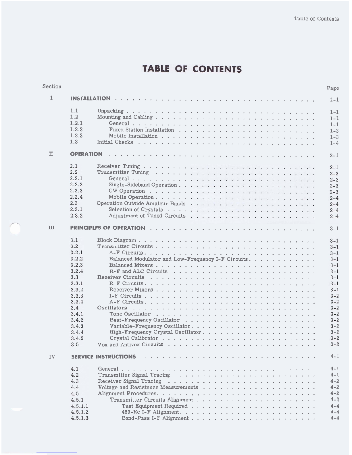
Table of Contents
Section Page
I
INSTALLATION
...................................
1-1
1.1 Unpacking
.................................
1-1
1.2 Mounting and Cabling
............................
1-1
1.2.1 General
................................
1-1
1.2.2 Fixed Station Installation
........................
1-3
1.2.3 Mobile Installation
...........................
1-3
1.3 Initial Checks
...............................
1-4
11
OPERATION
....................................
2-1
........
Receiver Tuning
Transmitter Tuning
......
General
..........
Single-Sideband Operation
.
.
CW Operation
.......
Mobile Operation
......
Operation Outside Amateur Bands
Selection of Crystals
....
Adjustment of Tuned Circuits
I11
PRINCIPLES OF OPERATION
.............................
3-1
Block Diagram
...............................
Transmitter Circuits
............................
A-F Circuits
..............................
Balanced Modulator and Low-Frequency I-F Circuits
............
Balanced Mixers
............................
R-F
and ALC Circuits
.........................
.............................
Receiver Circuits
R-F Circuits
..............................
Receiver Mixers
............................
I-F Circuits
..............................
A-F Circuits
..............................
Oscillators
................................
............................
Tone Oscillator
.......................
Beat-Frequency Oscillator
......................
Variable-Frequency Oscillator
....................
High-Frequency Crystal Oscillator
Crystal Calibrator
...........................
Vox and Antivox Circuits
..........................
IV
SERVICE INSTRUCTIONS
..............................
4-1
General
..................................
4-1
Transmitter Signal Tracing
.........................
4-1
..........................
Receiver Signal Tracing 4-2
Voltage and Resistance Measurements
....................
4-2
Alignment Procedures
............................
4-2
Transmitter Circuits Alignment
.....................
4-2
Test Equipment Required
......................
4-4
455-Kc
I-F
Alignment
........................
4-4
Band-Pass I-F Alignment
......................
4-4
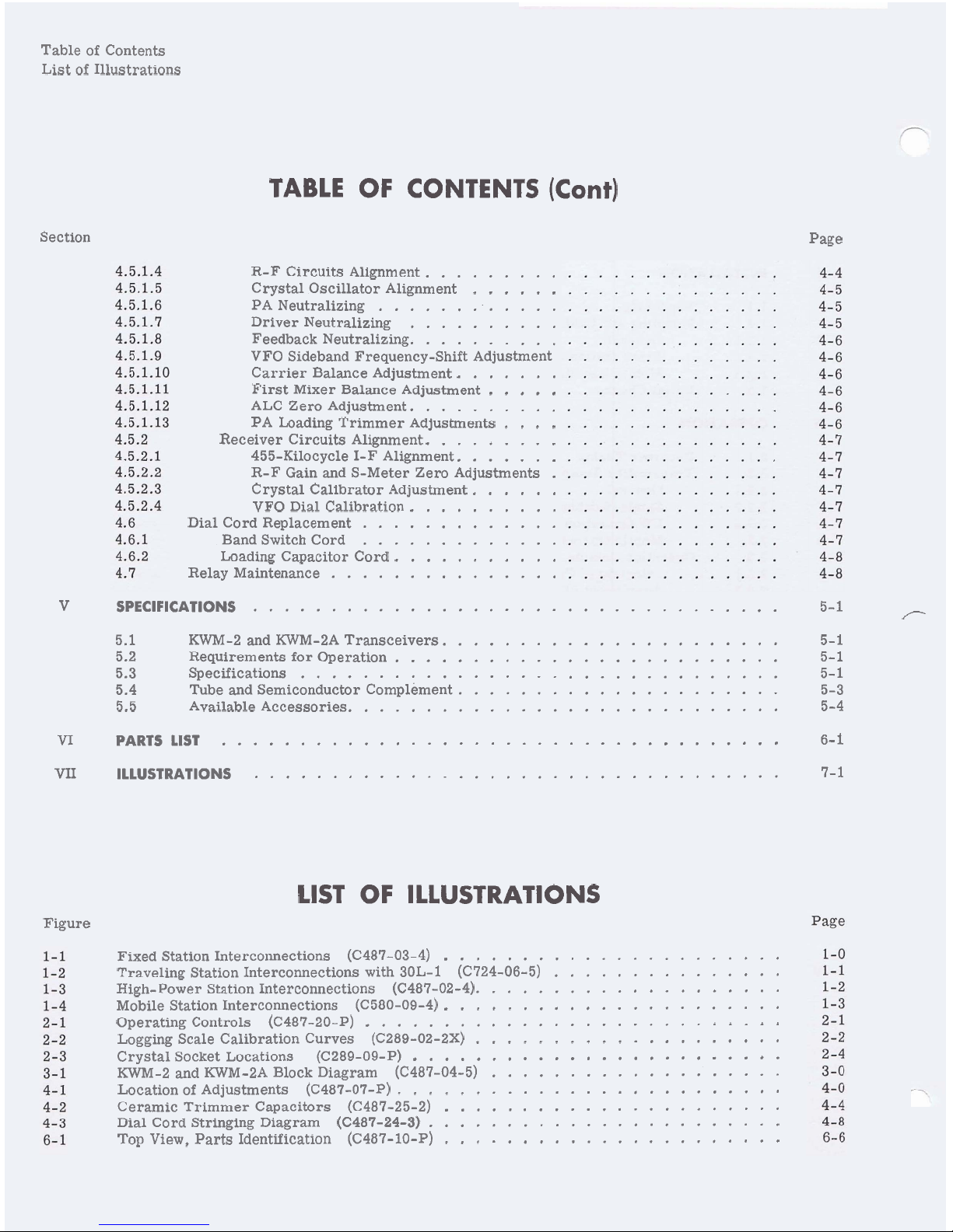
Table of Contents
List of Illustrations
TABLE
OF CONTENTS
(Cont)
Section
Page
R-F Circuits Alignment
.........
......
Crystal Oscillator Alignment
PA Neutralizing
............
Driver Neutralizing
..........
Feedback Neutralizing
..........
VFO Sideband Frequency-Shift Adjustment
.......
Carrier Balance Adjustment
.....
First Mixer Balance Adjustment
ALC Zero Adjustment
..........
....
PA Loading Trimmer Adjustments
.........
Receiver Circuits Alignment
.......
455-Kilocycle I-F Alignment
R-F Gain and S-Meter Zero Adjustments
.
......
Crystal Calibrator Adjustment
..........
VFO Dial Calibration
Dial Cord Replacement
.............
Band Switch Cord
.............
...........
Loading Capacitor Cord
Relay Maintenance
...............
V
SPECIFICATIONS
..................................
5-1
T--
5.1 KWM-2
and
KWM-2A Transceivers
......................
5-1
5.2 Requirements for Operation
.........................
5-1
5.3 Specifications
...............................
5-1
5.4 Tube and Semiconductor Complement
.....................
5-3
5.5 Available Accessories
............................
5-4
....................................
VI
PARTS LIST
6-1
VII
ILLUSTRATIONS
..................................
7-1
LIST
OF
ILLUSTRATIONS
Figure
......................
Fixed Station Interconnections (C487-03-4)
...............
Traveling Station Interconnections with 30L-1
(C724-06-5)
....................
High-Power Station Interconnections (C487.02.4)
......................
Mobile Station Interconnections (C580-09-4)
...........................
Operating Controls (C487-20-P)
....................
Logging Scale Calibration Curves (C289-02-2X)
........................
Crystal Socket Locations (C289-09-P)
KWM-2 and
KWM-2A Block Diagram (C487-04-5)
...................
.........................
Location of Adjustments (C487-07-P)
......................
Ceramic Trimmer Capacitors (C487-25-2)
Dial Cord Stringing Diagram
(C487-24-3)
.......................
......................
Top View. Parts Identification (C487-10-P)
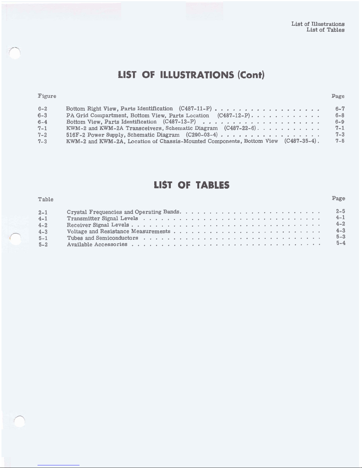
List of Illustrations
List of Tables
LlST OF ILLUSTRATIONS
(Cont)
Figure Page
..................
6-2 Bottom Right View, Parts Identification (C487-11-P)
6- 7
6-3 PA Grid Compartment, Bottom View, Parts Location (C487-12-P).
...........
6-8
....................
6-4 Bottom View, Parts Identification (C487-13-P)
6-9
7-1 KWM-2 and
KWM-2A Transceivers, Schematic Diagram (C487-22-6).
..........
7-
1
.................
7-2 516F-2 Power Supply, Schematic Diagram (C290-03-4)
7-3
7-3 KWM-2 and KWM-PA, Location of Chassis-Mounted Components, Bottom View
(C487-35-4). 7-5
LlST OF TABLES
Table Page
2-1 Crystal Frequencies and Operating Bands. ....................... 2-5
4-1 Transmitter Signal Levels
..............................
4-
1
4-2 Receiver Signal Levels
................................
4-2
4-3 Voltage
and
Resistance Measurements
.........................
4-3
5-1 Tubes and Semiconductors
..............................
5-3
5-2 Available Accessories
................................
5-4
TO KEY
SEE NOTE
8
SEE NOTE
6
a
+3
(D
c.
I
SEE NOTE 10
CI
PHONE LINE
a
SEE NOTE
7
tD
a
%
$
0
3
u
NOTES: PHONES
a
SEE
MICROPHONE
tD
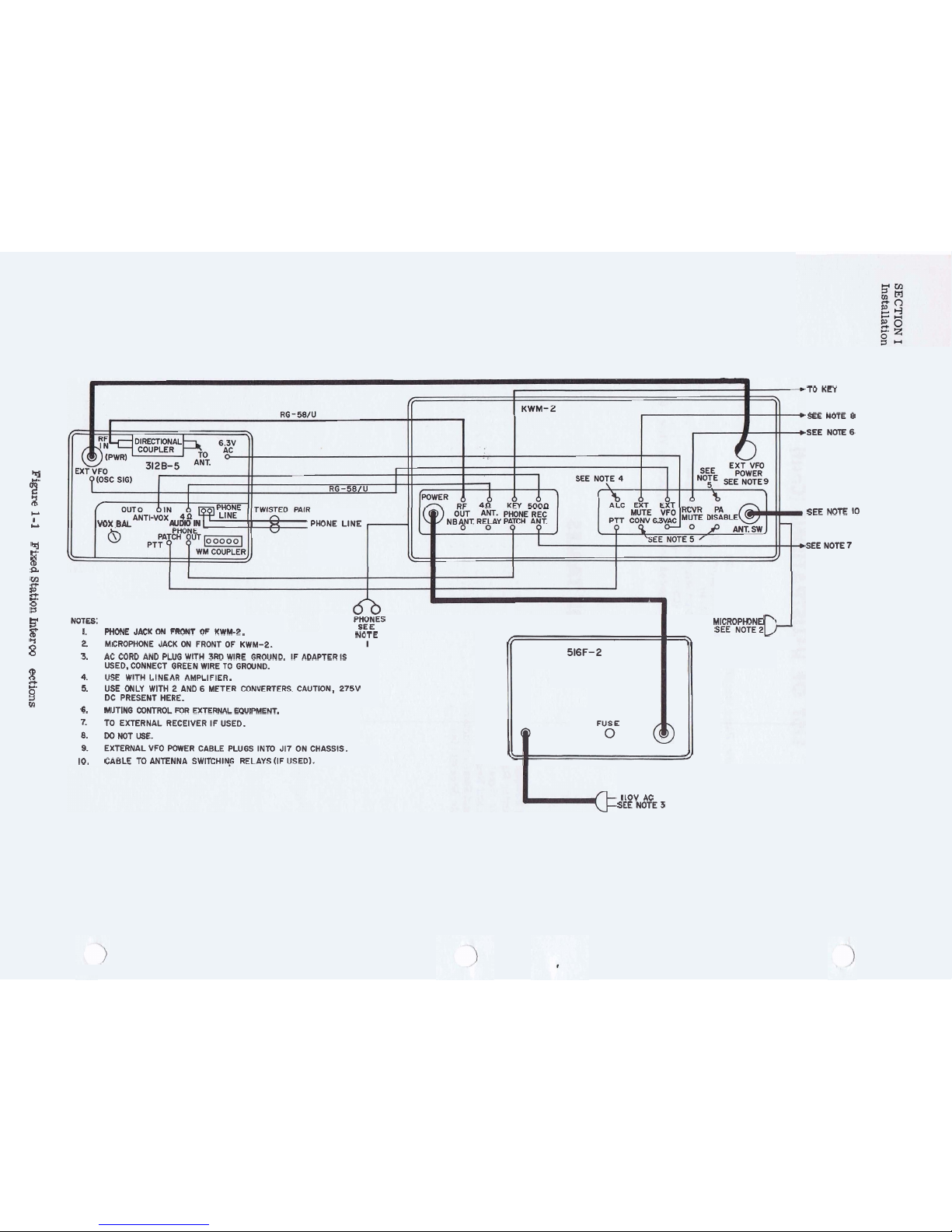
I.
PHONE JACK ON FRONT OF KWM-2.
NOTE
5
0
2.
MICROPHONE JACK ON FRONT OF KWM-2.
I
f;
\+
0
3.
AC CORD AND PLUG WITH 3RD WIRE GROUND.
IF ADAPTER IS
516F-2
(D
USED, CONNECT GREEN WlRE TO GROUND.
4.
USE WlTH LINEAR AMPLIFIER.
B
0
5.
USE ONLY WlTH 2 AND 6 METER CONVERTERS. CAUTION, 275V
2
DC PRESENT HERE.
6.
MUTING CONTROL FOR EXTERNAL EQUIPMENT.
7.
TO
EXTERNAL RECEIVER IF USED. FUSE
8.
DO
NOT USE.
@
0
9.
EXTERNAL VFO POWER CABLE PLUGS INTO J17 ON CHASSIS.
//
10.
CABLE
TO
ANTENNA SWITCHING RELAYS (IF USED).
e
llOV AC
SEE NOTE
3
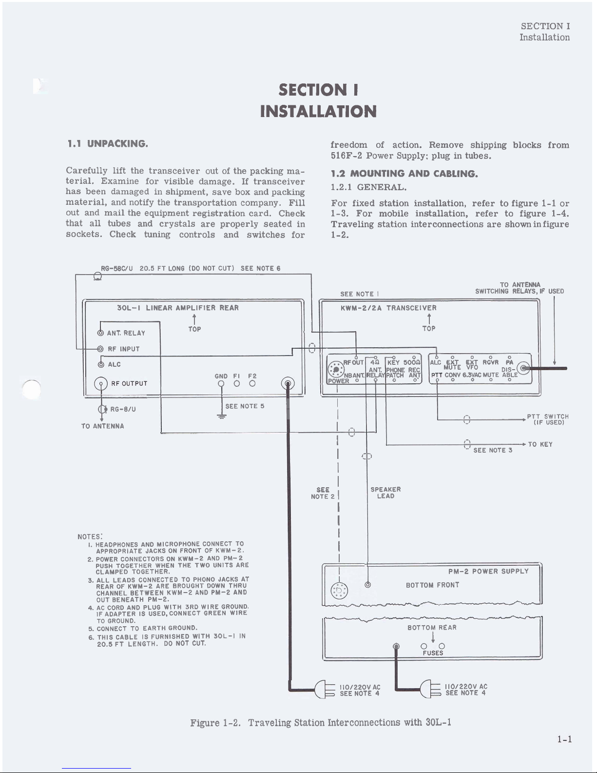
SECTION I
Installation
SECTION
I
INSTALLATION
1.1
UNPACKING.
Carefully lift the transceiver out of the packing material. Examine for visible damage. If transceiver
has been damaged in shipment, save box and packing
material, and notify the transportation company. Fill
out and mail the equipment registration card. Check
that all tubes and crystals are properly seated in
sockets. Check tuning controls and switches for
freedom of action. Remove shipping blocks from
516F-2
Power Supply: plug in tubes.
1.2
MOUNTING AND CABLING.
1.2.1
GENERAL.
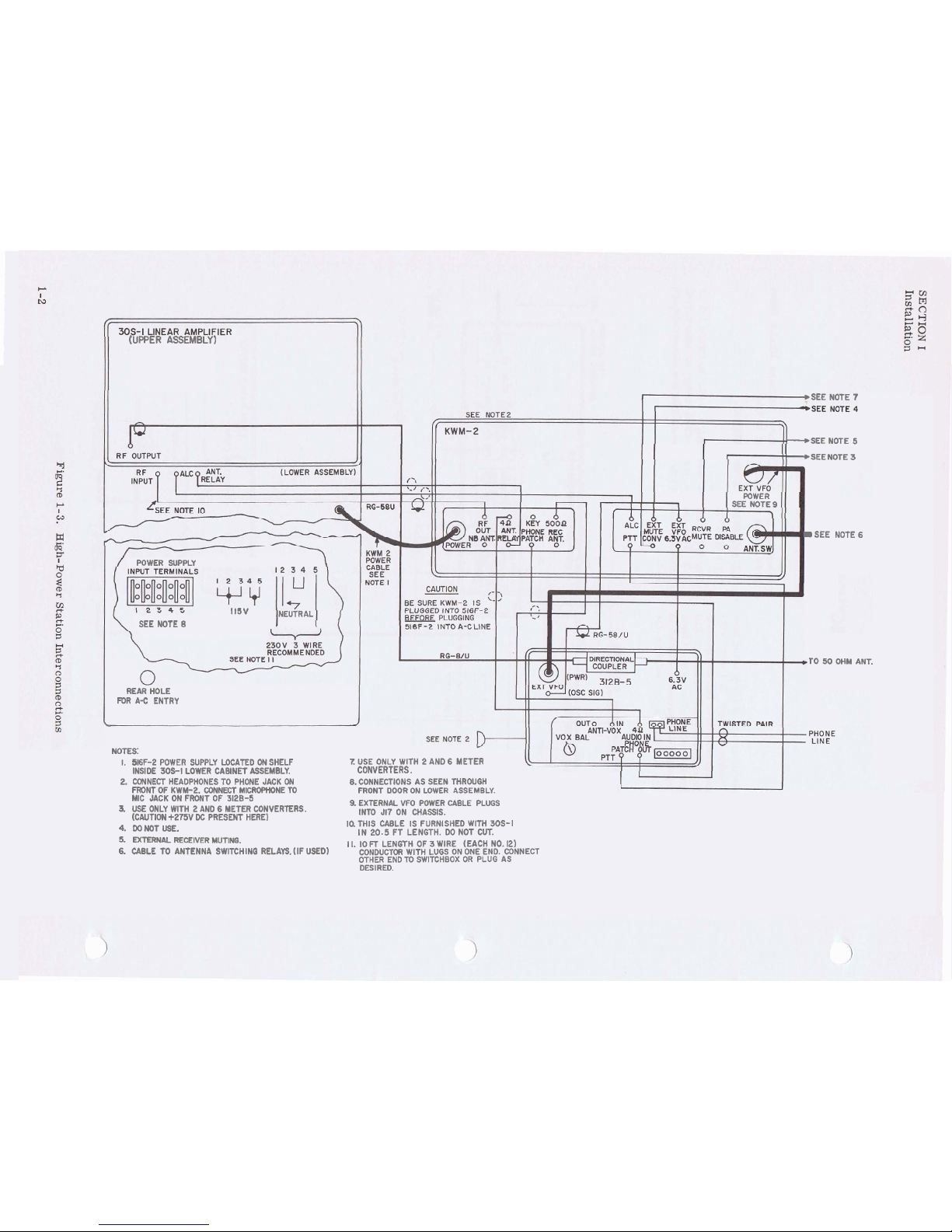
For fixed station installation, refer to figure
1-1
or
1-3.
For mobile installation, refer to figure
1-4.
Traveling station interconnections are shown in figure
1-2.
RG-5BCIU 20.5 FT LONG (DO NOT CUT) SEE NOTE
6
I
L1
I
Figure
1-2.
Traveling Station Interconnections with 30L-1
30L-
I
LINEAR AMPLIFIER REAR
t
TOP
TO ANTENNA
SEE NOTE
I
SWITCHING RELAYS, IF USED
KWM-2/2A TRANSCEIVER
t
-
I-,
--
+
>
TOP
0
0 0
ANT. RELAY
4
RF INPUT
ALC
II
,PTT SWITCH
$2
(IF USED)
t-j
TO KEY
'-I
SEE NOTE 3
Clr
SPEAKER
LEAD
RF&T%
ONBANT.
.POWER
0
I
(3)
RG-B/U
SEE NOTE 5
I
-
-
t
-
I
GND FI F2
TO ANTENNA
NOTES:
I.
HEADPHONES AND MICROPHONE CONNECT TO
APPROPRIATE JACKS ON FRONT OF KWM-2.
2. POWER CONNECTORS ON KWM-2 AND
PM-2
PUSH TOGETHER WHEN THE TWO UNITS ARE
I
I
,-,
1
'-I
I
I
SEE
I
NOTE 2
1
I
I
I
I
I
CLAMPED TOGETHER.
3. ALL LEADS CONNECTED TO PHONO JACKS AT
REAR OF KWM-2 ARE BROUGHT DOWN THRU
CHANNEL BETWEEN KWM-2 AND PM-2 AND
OUT BENEATH PM-2.
4.
AC CORD AND PLUG WlTH 3RD WlRE GROUND.
IF ADAPTER IS
USED.CONNECT GREEN WlRE
TO GROUND.
5. CONNECT TO EARTH GROUND.
6.
THIS CABLE IS FURNISHED WlTH 30L-I IN
20.5 FT LENGTH.
DO
NOT CUT.
&p
SEE NOTE
4
SEE NOTE
4
PM-2 POWER SUPPLY
BOTTOM FRONT
-
BOTTOM REAR
1
Q
ZY
5081;
'A&
EBT
E~T
RCVR
F?A
110/220V AC
Fyi
15
110/220V AC
:;:
:+
M!TE ~!cE@
3
(UPPER ASSEMBLY)
b
SEE NOTE
7
-SEE NOTE 5
+SEE NOTE
3
POWER
SEE NOTE 9
D
SEE NOTE
6
POWER SUPPLY
115V
NEUTRAL
SEE NOTE
8
r0
50 OHM ANT.
REAR HOLE
mR
A-c
ENTRY
i
NOTES:
1.
5EF-2 POWER SUPPLY WCATED
ON
SHELF
Z
USE ONLY WITH 2 AND 6 METER
INSIDE
30s-I
LOWER CABINET ASSEMBLY.
CONVERTERS.
2. CONNECT HEADPHONES TO PHONE JACK ON 8. CONNECTIONS AS SEEN THROUGH
FRONT OF KWM-2. CONNECT MICROPHONE TO
FRONT DOOR ON LOWER ASSEMBLY.
MIC JACK ON FRONT OF 3128-5
3.
USE ONLY WlTH 2 AND 6 METER CONVERTERS.
9.EXTERNALVFO POWERCABLE PLUGS
(CAUTION +275V
DC
PRESENT HERE)
INTO J17 ON CHASSIS.
4.
DO
NOT
USE.
IQ THIS CABLE IS FURNISHED WlTH 30s-1
IN 20.5 FT LENGTH. DO NOT CUT.
5.
EXTERNAL RECEIVER MUTING.
11. 10
FT
LENGTH OF 3 WIRE (EACH NO. 12)
6.
CABLE TO ANTENNA SWITCHING RELAYS. (IF USED)
CONDUCTOR WITH LUGS ON ONE END. CONNECT
OTHER END
TO
SWITCHBOX OR PLUG AS
DESIRED.
SECTION I
Installation
NTENNA
IF USED
ANTENNA
1.2.2 FIXED STATION INSTALLATION.
Connect associated equipment to the KWM-2 or
KWM-2A as shown in figure
1-1
or 1-3. Connection
at
525 may be used for automatic antenna changeover
I
I
I
REAR OF 3511)-2
I
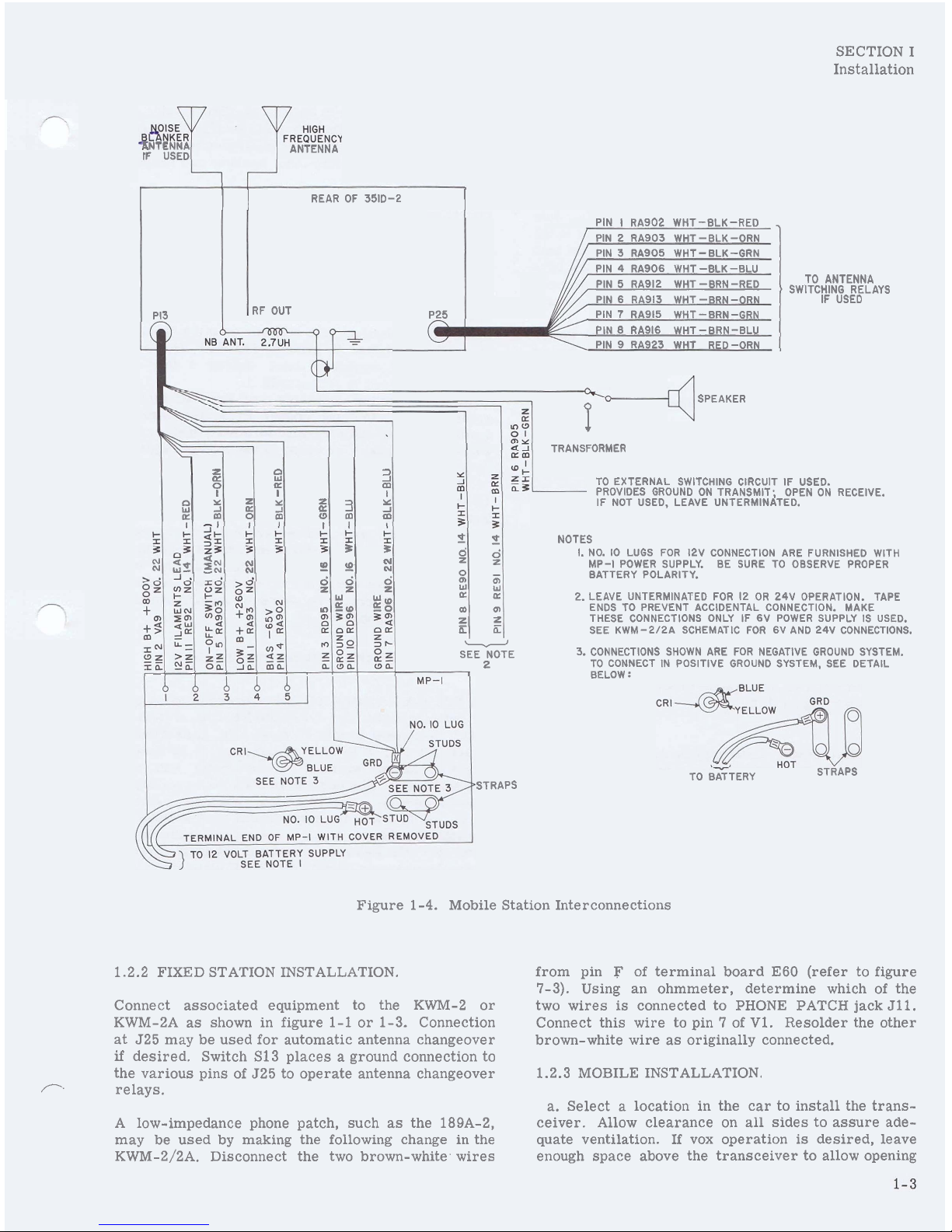
Figure
1-4.
Mobile Station Interconnections
PI3
from pin F of terminal board
E60
(refer to figure
7-3).
Using an ohmmeter, determine which of the
two wires
is
connected to PHONE PATCH jack
Jll.
Connect this wire to pin 7 of V1. Resolder the other
brown-white wire as originally connected.
if
desired. Switch S13 places a ground connection to
the various pins of
525 to operate antenna changeover
PIN I RA902 WHT-BLK-RED
,
/--.
relays.
PIN 2 RA903 WHT -8LK-ORN
PIN 3 RA905 WHT-BLK-GRN
PIN 4
RA906 WHT -BLK -BLU
PIN 5 RA912 WHT -BRN -RED
PIN
6
RA913 WHT -BRN-ORN
RF OUT P25
PIN 7 RA915 WHT -BRN-GRN
PIN 8 RA916 WHT-BRN-BLU
PIN 9
RA923 WHT RED -0RN
SPEAKER
Y
TRANSFORMER
A low-impedance phone patch, such
as
the 189A-2,
may be used by making the following change in the
KWM-2/2A. Disconnect the two brown-white. wires
TO ANTENNA
,
SWITCHING
RELAYS
IF USED
Z
a
o
I
1.2.3 MOBILE INSTALLATION.
a. Select a location in the car to install the trans-
ceiver. Allow clearance on all sides to assure adequate ventilation. If vox operation is desired, leave
enough space above the transceiver to allow opening
PYZY
WJLA
amom
I
I
0
w
a
I
S
%
3
?
0
a
d
M
2%
3:
ES
N
N
2
Z
0
-
dd
0
m
m
w
W
a
a
m m
Z Z
a
a
NOTES
I.
NO.
10
LUGS FOR 12V CONNECTION ARE FURNISHED WITH
MP-I POWER SUPPLY. BE SURE TO OBSERVE PROPER
BATTERY POLARITY.
2. LEAVE UNTERMINATED FOR 12 OR 24V OPERATION. TAPE
ENDS TO PREVENT ACCIDENTAL CONNECTION. MAKE
THESE CONNECTIONS ONLY IF 6V POWER SUPPLY IS USED.
SEE
KWM-2/2A SCHEMATIC FOR 6V AND 24V CONNECTIONS.
23
a~
em
u
SEE NOTE
3.
CONNECTIONS SHOWN ARE FOR NEGATIVE GROUND SYSTEM.
2
TO CONNECT IN POSITIVE GROUND SYSTEM, SEE DETAIL
BELOW:
TO BATTERY
STRAPS
STRAPS
3
J
m
I
Y
J
m
TO EXTERNAL SWITCHING CIRCUIT IF USED.
PROVIDES GROUND ON TRANSMIT* OPEN ON RECEIVE.
IF
NOT
USED, LEAVE
UNTERMIN~TED.
SECTION I
Installation
the top cover for adjustment of VOX and ANTI-VOX
gain controls, S-meter zero, etc.
If
351D-2 Mobile
Mount is to be use,, drill holes andfasten the adapter
bracket to tran mission hump with self
-
tapping
screws. Attach
i"
he mount to the bracket. Swing the
cantilever supports forward. Install the side slides
in
KWM-2/2A according to 351D-2 Mobile Mount
Installation Instructions. Remove the plastic dust
covers from the 351D-2 plugs, and store them in the
recesses of the mount. Slide the transceiver onto
the mount and push back until the mount plugs have
entered the transceiver sockets. Tighten the wing nuts
on the sides of the transceiver. See 351D-2 Instruction Sheet for mobile mount installation.
b. Select location in car for mounting MP-1 Power
Supply. This location must be as clean and dry as
possible. Location in luggage compartment, under
seat, or on passenger side of fire wall
is
satisfactory.
Mounting in the engine compartment
is
not
recommended.
c. Determine necessary length of power cable (Furnished with
351D-2 Mobile Mount) to connect the
MP-1 to the KWM-~/~A, and cut to required length.
Connect power supply, speaker, and microphone as
shown in figure
1-4.
If
automatic antenna changeover
is desired, connect relay coil ground returns to
525.
Before making connections to the automobile
electrical system, make sure the primary
circuits in the MP-1 are connected for proper
ground polarity. Correct connections for
either positive or negative groundsystems are
shown in figure 1-4.
The 440E-1 Power Cable may be used to connect the
power supply to the transceiver when the 351D-2 is
not used. See table 5-2 for ordering information.
d.
If
operation
is
to be in boat or plane having a
115-volt, 400-cps power supply, use 516F-2 Power
Supply with
C1 (0.05
uf)
removed from across L1
in the filter circuit.
If
the operation
is
to be in boat
or plane having 24-volt d-c power, modify the
516F-2
as above and use a dc-to-400 cps inverter capable
of at least 475-watt load.
e. No mobile speaker
is
supplied.
If
desired, the
speaker leads may be connected in parallel with the
car radio voice coil terminals.
If
the car radio has
a transistor output stage, connect the terminals of the
car speaker as shown in figure 1-4. Break voice coil
lead, and install a switch for transfer of speaker from
,P
car radio to KWM-2/2A. If installation
is
in boat or
plane, use any good four-ohm speaker and mount as
desired.
f. For suppression of noise encountered in mobile
operation, the following suggestions may be helpful:
(1) Use resistor-type spark plugs.
(2) Install coaxial bypass capacitors at ignition
coil, generator, and voltage-regulator leads. Use
bracket-mounted coaxial capacitors in the battery
and generator leads to the voltage regulator and a
0.005-uf (or smaller) disc ceramic or mica capacitor
from the field lead to ground. DO NOT use larger
than 0.005-uf capacitor here unless a four-ohm
resistor
is
placed in series with it.
(3)
If
capacitor bypasses are not satisfactory,
remove them, and use chokes in series with the
leads from field and armature terminals of generator.
Place these chokes as close to the voltage regulator
as possible.
(4)
For the field lead choke, wind 12 turns of no.
18 wire on a
1/4-inch diameter powdered-iron core.
For the armature lead, wind 12 turns of no. 14 or
larger wire on
1/4-inch diameter powdered-iron core.
(5) Ground the rear end of the exhaust pipe to the
car body with copper braid, using a radiator hose
clamp to secure the braid to the tailpipe. General
information concerning noise suppression
is
available
in current handbooks.
1.3
INITIAL
CHECKS.
(Refer to figure
2-1.)
Set MIC GAIN control (4) full counterclockwise until
the switch clicks. Set OFF-ON-NB-CAL switch (1)
to ON. Set meter switch (8) to PLATE,
andEMISSION
switch (2) to LOCK. The transceiver is in receive
condition during
warmup, so the meter will read
full scale until filaments have come to temperature.
This
is
normal S-meter action. When the S-meter
falls back to zero, the circuits will have switched to
transmit condition, and the meter will indicate PA
plate current. Read the no-signal PA plate current.
It should be approximately 40 ma.
If
plate current
is
other than 40 ma, adjust
BIAS
ADJUST potentiometer
on top rear of power supply chassis to set plate current
to 40 ma.
If
the transceiver
is
to be used with a linear
amplifier, set bias to produce 50-ma idling plate
current.
SECTION
n
Operation
SECTION
I1
OPERATION
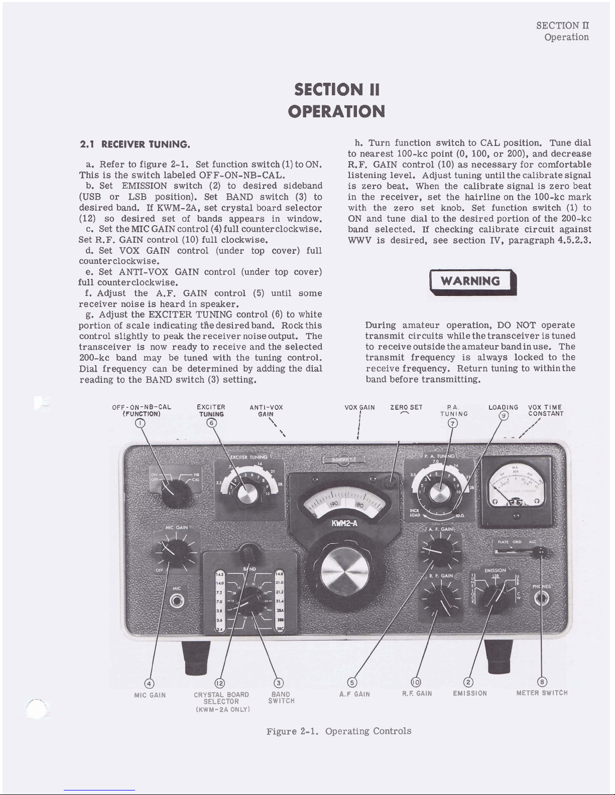
2.1
RECEIVER
TUNING.
a. Refer to figure 2-1. Set function switch (1) to ON.
This is the switch labeled OFF-ON-NB-CAL.
b. Set EMISSION switch (2) to desired sideband
(USB or LSB position). Set BAND switch (3) to
desired band.
If
KWM-2A, set crystal board selector
(12) so desired set of bands appears in window.
c. Set the MIC GAIN control (4) full counterclockwise.
Set R.F. GAIN control (10) full clockwise.
d. Set VOX GAIN control (under top cover) full
counterclockwise.
e. Set ANTI-VOX GAIN control (under top cover)
full counterclockwise.
f.
Adjust the A.F. GAIN control (5) until some
receiver noise
is
heard in speaker.
g. Adjust the EXCITER TUNING control
(6)
to white
portion of scale indicating
tAe desired band. Rock this
control slightly to peak the receiver noiseoutput. The
transceiver
is
now ready to receive and the selected
200-kc band may be tuned with the tuning control.
Dial frequency can be determined by adding the dial
reading to the BAND switch
(3)
setting.
h. Turn function switch to CAL position. Tune dial
to nearest 100-kc point (0, 100, or
200), and decrease
R.F. GAIN control (10)
as
necessary for comfortable
listening level. Adjust tuning until the calibrate signal
is
zero beat. When the calibrate signal is zero beat
in the receiver, set the hairline on the 100-kc mark
with the zero set knob. Set function switch (1) to
ON and tune dial to the desired portion of the 200-kc
band selected.
If
checking calibrate circuit against
WWV
is
desired,
see
section IV, paragraph 4.5.2.3.
I
WARNING
During amateur operation, DO NOT operate
transmit circuits while the transceiver
is
tuned
to receive outside the amateur bandinuse. The
transmit frequency is always locked to the
receive frequency. Return tuning to within the
band before transmitting.
OFF-ON-NB-CAL EXCITER ANTI-VOX VOX FAIN ZERO SET
(FUNCTION) GAl?
I
'\
I
'\
I
I
--
LOADING VOX TIME
CONSTANT
MIC GAIN CRYSTAL BOARD BAND A.F GAIN
R.F. GAIN EMISSION METER SWITCH
SELECTOR SWITCH
(KWM-PA ONLY)
Figure 2-1. Operating Controls
SECTION
11
Operation
FREQ
(MC)
FRE9
(MC)
Figure
2-2.
Logging
Scale Calibration Curves
SECTION
11
Operation
2.2
TRANSMITTER TUNING.
2.2.1 GENERAL.
a. Set up for receive function
as
in paragraph 2.1.
b. Set EMISSION switch (2) to TUNE position.
c. Set P.A. TUNING control
(7)
to white portion of
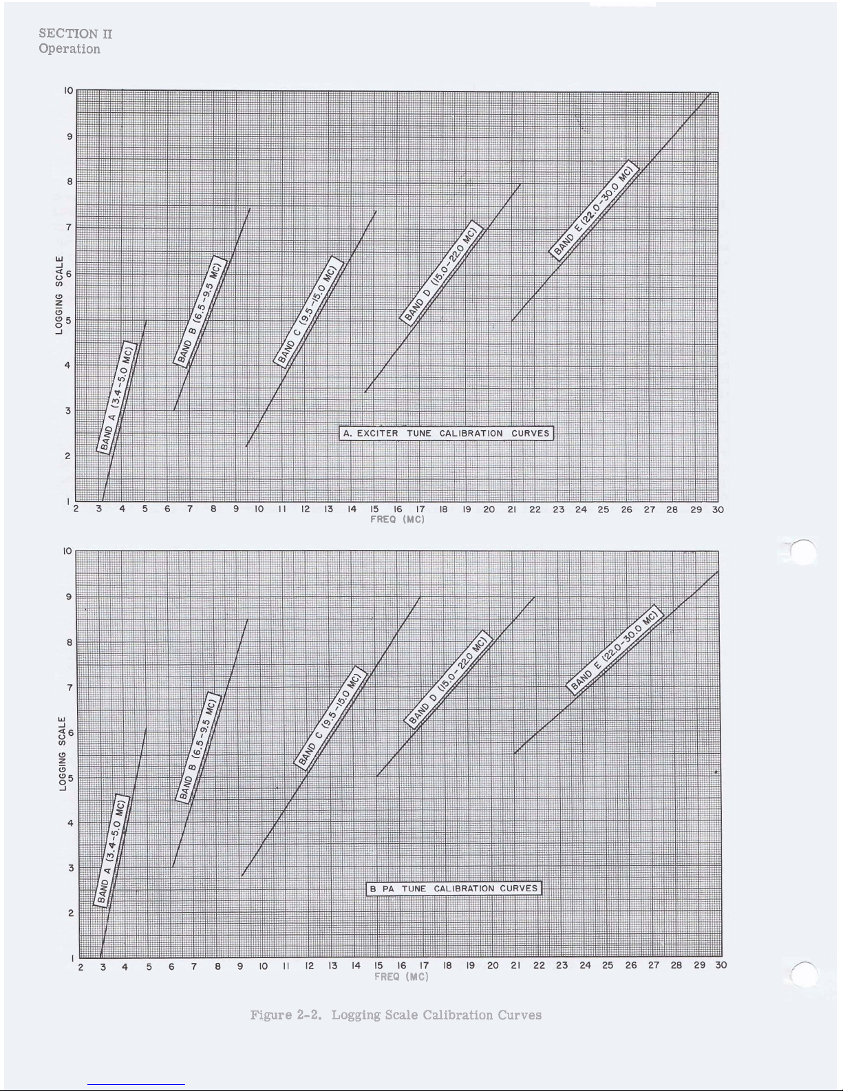
dial indicating the desired band (for amateur oDera-
e. Advance the MIC GAIN control (4) full clockwise,
and rock the EXCITER TUNING control
(6)
until
maximum plate current is obtained.
f.
IMMEDIATELY dip the plate current with the
P.A. TUNING control (7).
g. Return the MIC GAIN control (4) to full counter-
clockwise position.
h. Set meter switch (8) to GRID position.
i. Advance MIC GAIN control (4) until grid current
is obtained.
j.
Rock the EXCITER TUNING control (6) to obtain
a peak in grid current indication.
k. Turn MIC GAIN off.
1. Set EMISSION switch to LOCK position.
m. Advance MIC GAIN to provide a grid current
reading of approximately 1/3 scale.
n. Set meter switch to PLATE position.
o. Alternately dip plate current with P.A. TUNING
control, and adjust loading with INCR LOAD control
until plate current
is
230 maat the dip. When operating
the transceiver with a linear amplifier, load to only
200 ma.
p. Set EMISSION switch to desired operating position.
If
transceiver frequency is changedby any great
amount, be sure to redip the power amplifier
plate current and check the loading. This will
be most important on the 80- and 40-meter
bands. Some operating experience will indi-
cate the amount of frequency excursion possible
without readjustment.
2.2.2 SINGLE-SIDEBAND OPERATION.
a.
Set up receiver operation and transmitter opera-
tion completely as in paragraphs 2.1 and 2.2.1.
b. Close-talk into the microphone, increasing VOX
GAIN control setting until vox relay just operates. For
vox operation, it
is
desirable to close-talk the micro-
phone to prevent background noises from tripping the
KWM-~/~A into transmit function.
c. Set meter switch (8) to ALC position. Increase
setting of MIC GAIN control (4) to obtain S6 average
reading on voice.
d. Leave MIC GAIN control
(4)
as setinstep c above.
Leave microphone in normal operating position.
Set
function switch to CAL position, tune in calibrate
signal, and adjust A.
F.
GAIN control
(5)
for comfortable
listening level.
e. Adjust the tuning control for approximately
1000-
cps beat note.
If
the vox relay trips, increase ANTI-
VOX GAIN setting to
minimum point necessary to
prevent speaker output from tripping vox. It may be
necessary to increase VOX GAIN setting slightly after
this antivox gain adjustment in order to compensate
for the antivox gain.
NOTE
Do not use more vox gain or more antivox
gain then necessary to control vox operation.
If
vox circuits transfer between words, in-
crease the
releage time constant by turning
VOX TIME CONSTANT control (under top
cover) clockwise.
If
less
release time is de-
sired, turn the control counterclockwise.
f. Set function switchto ONposition. The KwM-~/~A
is now ready for transmit operation in SSB service.
Speaking into the microphone transfers from receive
function to transmit function through the vox circuit
action.
If
the receiver
is
tunedto a differentfrequency,
the transmitter is tuned to the new receiver frequency.
g. After changingfrequency on the lower bands (below
10 mc), set EMISSION switch (2) to
LOCKposition and
make the following checks:
(1) Set meter switch (8) to GRID poiition.
(2) Rock EXCITER TUNING control
(6)
slightly to
check that PA grid drive
is
peaked.
(3) Set meter switch (8) to PLATE, and check dip in
PA plate current with P.A. TUNING control (7).
(4) Set EMISSION switch back to the desired
operating position.
2.2.3 CW OPERATION.
a. Set the function switch to
ON.
b. Set up receiver and transmitter operation com-
pletely as in paragraphs 2.1 and 2.2.1.
c. Depress key and adjust A.F. GAIN control
(5)
for comfortable monitoring level.
d. Hold key down, and increase VOX GAIN control
setting until the vox relay operates.
If
it is desired to
change the release time constant, adjust the VOXTIME
CONSTANT potentiometer,
R43. Clockwise rotation of
this control increases the
release
time. This control
is
located on a bracket under the top cover, behind the
meter.
e. Set meter switch (8) to ALC position. While send-
ing
a
series
of dots, adjust MIC GAIN control (4) for
S2 meter indication of
alc.
f. When receiving, leave the A.F. GAIN control
(5)
set for comfortable monitoring level, and adjust the
receive level with the R.F. GAIN control (10). When
the
KWM-2/2A
is
receiving, the received signal
is
indicated in S-units. The S-meter
will
read correctly
with the
R.
F. GAIN (10) at less than maximum setting,
SECTION
II
Operation
provided the received signal level
is
high enough to
actuate the S-meter. For
example, if the R.F. GAIN
control (10) is set for no-signal reading of S8 and
reads
S9 with signal, the received signal
is
S9.
NOTE
The CW output signal frequency
is
1500 cps
higher than the dial reading.
2.2.4 MOBILE OPERATION.
Vox and antivox circuits will operate in mobile operation, but push-to-talk operation
is
recommended, since
high-level background noises will produce undesirable
vox switchover. Set VOX GAIN and ANTI-VOX GAIN
controls full counterclockwise before installation.
If
vox operation
is
desired, leave clearance in installation
so top cover can be opened. For mobile operation,
loack the power amplifier to 210-ma plate current.
2.3
OPERATION OUTSIDE AMATEUR BANDS.
2.3.1 SELECTION OF CRYSTALS.
The crystals supplied provide for complete coverage
of
all
amateur bands except the 10-meter band for
which only one crystal
is
furnished (for 28.5 to 28.7
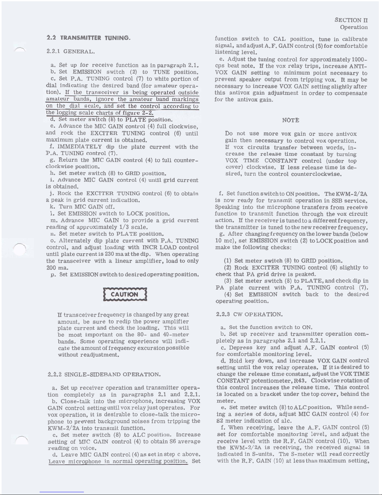
mc). Two extra sockets are provided for additional
crystals in the 10-meter band. Figure 2-3 shows
crystal socket locations. Select these crystals as
follows:
a.
If
the lower edge of the desired 200-kc band
is
11.8 mc or less, the required frequency
is
equal to the
lower edge of the desired band plus 3.155 mc. As an
example,
if
the desired band
is
4.0 to 4.2 mc, 4.0 mc
'
plus 3.155 mc equals 7.155 mc.
b.
If
lower edge of desired 200-kc band
is
12.00 mc
or higher, the required crystal frequency
is
half the
sum of the lower edge of desired band and 3.155 mc.
As an example, if the desired band
is
14.4 to 14.6 mc:
The plate circuit of the oscillator
is
tunedto twice the
crystal frequency when required inj ectionfrequencies
are this high.
Avoid transmitter operation between 5.0 and 6.5
mc. In this range, the second harmonic of the
variable i-f frequency
is
nearly the same as
desired frequency. In transmit function, some
of this energy will pass through the tuned circuits and become spurious emission.
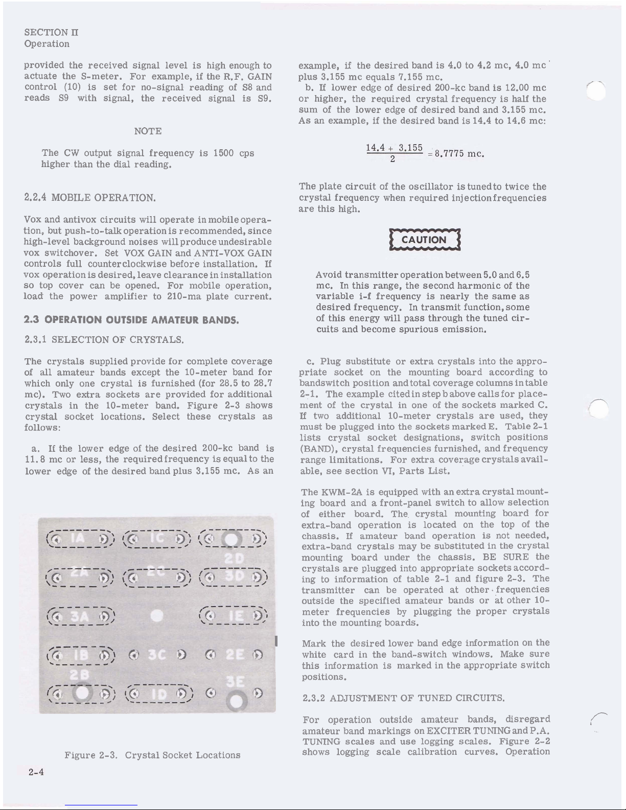
c.
Plug substitute or extra crystals into the appro-
priate socket on the mounting board according to
bandswitch position and total coverage columns in table
2-1. The example
citedin step b above calls for place-
ment of the crystal in one of the sockets marked C.
If
two additional 10-meter crystals are used, they
must be plugged into the sockets
markedE. Table 2-1
lists crystal socket designations, switch positions
(BAND), crystal frequencies furnished, and frequency
range limitations. For extra coverage crystals available, see section
VI,
Parts List.
The KWM-2A
is
equipped with an extra crystal mount-
ing board and
a
front-panel switch to allow selection
of- either board.
he
crystal mounting board for
extra-band operation
is
located on the top of the
chassis.
If
amateur band operation
is
not needed,
extra-band crystals may be substituted in the crystal
mounting board under the chassis. BE SURE the
crystals are plugged into appropriate sockets according to information of table 2-1 and figure 2-3. The
transmitter can be operated at other. frequencies
outside the specified amateur bands or
at
other 10-
meter frequencies by plugging the proper crystals
into the mounting boards.
I
Mark the desired lower band edge information on the
white card in the band-switch windows. Make sure
this information
is
marked in the appropriate switch
positions.
2.3.2 ADJUSTMENT OF TUNED CIRCUITS.
For operation outside amateur bands, disregard
/-
amateur band markings on EXCITER TUNING and P.A.
TUMNG scales and use logging scales. Figure 2-2
Figure 2-3. Crystal Socket Locations
shows logging scale calibration curves. Operation
SECTION
n
Operation
at frequencies outside the amateur bands will result
in slightly decreased receiver sensitivity and
transmitter PA grid drive, unless the tuned circuits of
the transceiver are retuned to peak their responses
in the desiredportions of the high-frequency spectrum.
For moderate excursions from the amateur bands
the decrease in performance
is
minor, and realign-
ment of the
r-f
circuits isusually not necessary unless
optimum performance
is
desired.) Adjustment of the
trimmer capacitors only will normally be sufficient to
peak the response outside the amateur bands. Figure
4-1 shows the location of these adjustments. The letter
portions of the capacitor designations correspond to the
frequency ranges listed in the total coverage
columnof
table 2-1. For example, the E trimmers are normally
peaked on 10 meters, but may be reset to favor another
portion of band E which covers 22.0 to 30.0 mc.
At the extremities of some bands the PA loading may
be either too heavy or too light. This condition
can
be
corrected by the following procedure:
a. Remove the top cover from the PA compartment.
I
WARNING
b
Dangerous voltages are present withpower on.
Be sure that all power
is
disconnected before
working in this compartment.
b. Temporarily disconnect the existing wire f rom the
rear stator terminal of the two-gang loading capacitor.
c. Connect a jumper wire between front and rear
stator terminals, and replace the compartment cover.
NOTE
The 50 a mark on the loading control will no
longer be correct after this modification
is
made.
TABLE 2-1.
CRYSTAL FREQUENCIES AND OPERATING BANDS
BAND-SW1TCH
POSITION
1A
-
3.4
2A
-
3.6
3A
-
3.8
1B - 7.0
2B
-
7.2
1C - 14.0
2C
-
14.2
3C
-
14.8
1D - 21.0
2D
-
21.2
3D
-
21.4
1E - 28A
2E - 28B
3E
-
28C
FREQUENCY BAND
3.4 - 3.6 mc
3.6 - 3.8 mc
3.8 - 4.0 mc
7.0 - 7.2 mc
7.2 - 7.4 mc
14.0 - 14.2 mc
14.2 - 14.4 mc
14.8 - 15.0 mc
21.0 - 21.2 mc
21.2 - 21.4 mc
21.4 - 21.6 mc
28.5 - 28.7 mc
As selected
As selected
CRYSTAL SUPPLIED
6.555 mc
'
6.755 mc
6.955 mc
10.155
wc
10.355 mc
8.5775 mc
8.6775 mc
8.9775 mc
12.0775 mc
12.1775 mc
12.2775 mc
15.8275 mc
Not furnished
Not furnished
CRYSTAL
1A
2A
3A
1B
2B
1C
2C
3C
1D
2D
3D
1E
2E
3E
TOTAL COVERAGE
A 3.4 - 5.0 mc
B
6.5 - 9.5 mc
C
9.5 - 15.0 mc
D 15.0 - 22.0 mc
E 22.0 - 30.0 mc
 Loading...