

Collins 30L-l Instruction Book
Cedar Rapids Division I Co//ins Radio Company, Cedar Rapids, /owa
Collins
Amateur
Equipment
Guarantee
The
Collins
Amateur
Equ i
pm
nt
esc
r i
bed
he r ein
is
sold
under
the
follo
wing
guarantee
:
Collins
agrees
to
repair
I'
r
eplace
, wit hout
charge,
any
equipment,
parts,
or a
cesso
r ie ' whi c h
are
defective
as
to
workmanshi
p a
i'
mate
rials
and
which
are
returned
to
Collins
at its factor y or
Its
designated
Service
Agency,
tran
por tatio n prepa
id,
provided:
(a)
Buyer
presents
properly
executed
Wana
ty
Verification
Certificate,
(b)
Notice
of
the claimed
defeet
is
gi ven Co
llins
or
an
authorized
Servi
ce Acrency, or
an
authori
zed
Distributor,
in
writing;,
within
180 days from
the
date
of
purchase
and
goo
ds
are r tur
ned in
accordance
with
Collins
instructi
ons
,
(c)
Equipment,
accessories,
tubes,
and
batterl
es
not
manufactured
by
Collins
or from
Coll
ins
designs
are
subject
to only such
adjustments
as
Collins
may
obtain from th
supp
li r he r eof.
(d) Any
failure
due to
use
of e
quipm
ent
for
purposes
other
than
tho
s e
contemplated
in
normal
amateur
operati.
on
or in ViolatIOn
of
Collins
applicable
Instru
cti
on
k
shall
nOl
be
deemed a defect
within
the
mean
'ng of
these
provisions.
Thi
Warranty
is
void
with
respect
to
equipment
which
is
altered,
modified
or
repaired
by
other
than
Co lli
ns
or
Collins
Authorized
Service
Agencies.
How-
eve
r, alterati
on
or
modification
in
accordance
with
C
lli
ns e rvic e Bulletins
shall
not
affect
this
Warranty.
o
llins
reserves
the
right
to
make
any
change
in
design
o r to
make
additions
to,
or
improvements
in,
Collins roducts
without
imposing
any
obligations
upon
Collin to
install
them
in
previously
manufactured
Co
lli
ns
pro
ducts
.
No
other
warranties,
expressed
or
implied,
shall
be
applicable
to
said
equipment,
and
the
foregoing
s ha
ll constitute
the
Buyer's
sole
right
and
remedy
under
the
agreements
contained
in
these
paragraphs.
It
no
event shall
Collins
have
any
liability
for
con-
sequential
damages,
or
for
loss,
damage
or
expense
di
l' ctly or
indirectly
ariSing
from
the
use
of
the
pr odu
cts,
or
any
inability
to
use
them
either
separately
or il combination
with
other
equipment
or
materials
or fro m any
other
cause.
1\
TIC
E:
With
each
equipment
or
set
of
equipments
purchased,
the
distributor
should
furnish
a
Warranty
Verification
Certificate.
It
is
necessary
that
this
certificate
accompany
the
equipment
when
it
is
returned
for
warranty
repairs.
Be
sure
that
you
receive
~
from
your
distributor.
~
T
arrant)"
Repail's
On
the
opposite pao'e
are
li ted
[e
e1' i
ce
AgenCies
authorized
to pe
rform war r
an y repair
on
Collins
Amateur
Equipments.
If
you
Should
wish
to
retur
n material or
equipment
direct
to
Collins
under the
guarantee
, you
hould
no lfy
Collins,
giving'
full
particular
s i
nelu ing
the
deta
il
listed
below,
insofar
as
applicabl
e .
If
the nem
I.
thought
to be
defective,
such
noti
e mu
st
gi e fu
ll
information
as
to
nature
of
defe
ct
and iden
tificat
IOn
(including
part
number
if
possibl
e) of pa
rt
cons
ider d
defecti
ve.
Upon
receipt
of
such
notice, Coll
ins
will
promptly
advise
you
respecting
the
return.
Failure
to
secure
our
advice
prior
to
the
forwardi
ng of the
goods
or
failure
to
provide
full
particulars
may
cause
unnecessary
delay
in
handling
of
your
returned
merchandise.
. DDRESS:
Co
llins
Radio
Company
Am
ate
ur
Product
Office
Ceda r
Rapids,
Iowa
INFORMATION
NEEDED:
(A)
Type
number,
name
and
serial
number
of
equipment
(B)
Date
of
delivery
of
equipment
(C)
Date
placed
in
service
(D)
Number
of
hours
of
service
(E)
Nature
of
trouble
(F)
Cause
of
trouble
if known
(G)
Name
of
distributor
from
whom
the
equip-
ment
was
purchased.
Equipment
returned
to
the
Service
Agency
or
Collins
for
warranty
repair
must
be
accompanied
with
the
Warranty
Verification
Certificate.
Out-of-warranty
Repair,
Modifications,
Addition
of
Accessories,
AJignmen~
etc,
For
information
on
service
of
this
type
write
to
the
address
shown
below.
If
you
wish
to
return
your
equipment
for
repairs,
etc.,
without
prior
correspond-
ence,
be
sure
to
include
the
following
information
attached
to
the
equipment
inSide the
packing
carton:
(1)
Complete
instructions
performed.
(2)
Your
return
address.
(3)
Method
of
shipment
by
should
be
returned.
(4)
Special
instructions.
detailing
work
to be
which
the
equipment
DffiECT
YOUR
CORRESPONDENCE
TO:
Collins
Radio
Company
Product
Support
DiviSion
Cedar
Rapids,
Iowa
HOW
TO
ORDER
REPLACEMENT
PARTS:
When
ordering
replacement
parts,
please
furnish
the
following
information
insofar
as
applica
ble:
INFORMATION
NEEDED:
(A)
Quantity
required
(B)
Collins
part
number
'(9
or
10
digit
number)
and
description
(C)
Item
or
symbol
number
obtained
from
parts
list
or
schematic
(D)
Collins
type
number,
name
and
serial
number
of
principal
equipment
(E) Unit
subassembly
number
(where
applicable)
15
March
1965

523-0122000-007311
7th
Edit
ion,
15
February 1965
~
COLLINS
~
instruction
book
30L-l
R-F Linear Amplifier
©Colli
ns
Radio
Company
196/,
1962,
1964. 1"65
Cedar Rapids
Division
I Collins Radio Company, Cedar Rapids, Iowa
P
lll\lrd
In
U.
S.
A
Table
or C
ontents
TABLE
OF
CONTENTS
Section
Page
INSTALLATION .
..
1-1
1.1
Unpacking
1-1
1.2
Power
Transformer
Connections.
1-1
1.3
Cabling
.....•.
1-1
1.3.1
Traveling
station.
• . . . .
1-1
1.3.2
Home
Station.
. . . • . . .
1-1
1.3.3
KWM-1
Serial
Numbers
Above 861
1-5
1.3.4
KWM-1
Serial
Numbers
Below 861
1-5
1.4
Installation
with
Other
Makes
of
Exciters
1-5
II
OPERATION
............
. 2-1
2.1
Operation
in
Amateur
Bands
.
2-1
2.2
Operation
with
Other
Makes
of
Exciters.
2-1
2.3
Operation
Outside
Amateur
Bands
2-1
III
PRINCIPLES OF OPERATION
3-1
3.1
General
....
3-1
3.2
Input
Circuits
.
3 -1
3.3
Output
Circuits.
3-1
3.4
Power
Supply
Circuits
3-1
3.5
Saiety
Interlock
Circuits.
3-1
3.6
Power
Control
Circuits
3-1
3.7
ALC
Circuits
3-1
3.8
Metering
Circuits.
3-2
IV
MAINTENANCE . .
4 -1
4.1
General
4-1
4.2
Removal
of
Cabinet
and
Covers
4-1
4.3
Blower
Lubrication.
. . . . .
4-1
4.4
Alignment
of
R-F
Input
Circuits
4
-1
4.5
Meter
Lamp
Replacement
4-2
4.6
Tube
Replacement
. . . .
4-2
4.7
Tune
Meter
Adjustment
. .
4-2
4.8
ALC
Threshold
Adjustment
4-3
v
SPECIFICATIONS
5-1
VI
PARTS
LIST
6-1
VII
ILLUSTRATIONS
7-1
List
of
Illustrations
List
of
Tables
LIST
OF
ILLUSTRATIONS
Figure
Page
1-1
Interconnections
with
KWM-2/
2A
Traveling
Station
(C724-06-5).
1-0
1-2
Interconnections
with
KWM-2/
2A
Home
Station
(C724-04-5).
1-2
1-3
Interconnections
with
KWM-l
(C724-05-5).
1-3
1-4
Interconnections
with
S-Line
(C724-07-5).
1-4
2-1
30L-l
Operating
Controls
(C724-0B-P)
..
2-0
3-1
30L-l
Block
Diagram
(C724-02-4)
. . . .
3-0
3
-2
Control
and
Interlock
Circuits
(C724-03-4)
3-2
4-1
Location
of
Adjustments
(C724-10-P)
. . .
...
4-1
6-1
R-F
and
Power
Supply
Compartments,
Parts
Location
(C724-12-P)
6-0
6
-2
Input
Circuitry,
Parts
Location
(C724-11-P)
.
6-3
'7
-1
Connector
Assembly
Instructions
(C724-14-X)
7-1
'7
-2
30L-l
Schematic
Diagram
(C724-01-6)
...
7-3
LIST
OF
TABLES
Ta
ble
Page
1-1
Equipment
Furnished
with
30L-1
1-1
2-1
Multimeter
Scale
Values
. . . .
2-1
4-1
Frequency
Coverage
Allowable
by
Realignment
4-2
ii
SECTION
I
Installation
RG-5BC/U
RF
EXTENSION
CABLE
30L-1
LINEAR
AMPLI
F IER REAR
~
ANT. RELAY
~
RF
INPUT
@
ALC
RF
OUTPUT
::+
RG-8/U
TO
ANTENNA
NOTES
:
1
TOP
G~D
FI
F2
~~
0 0
SEE
NOTE
5
~
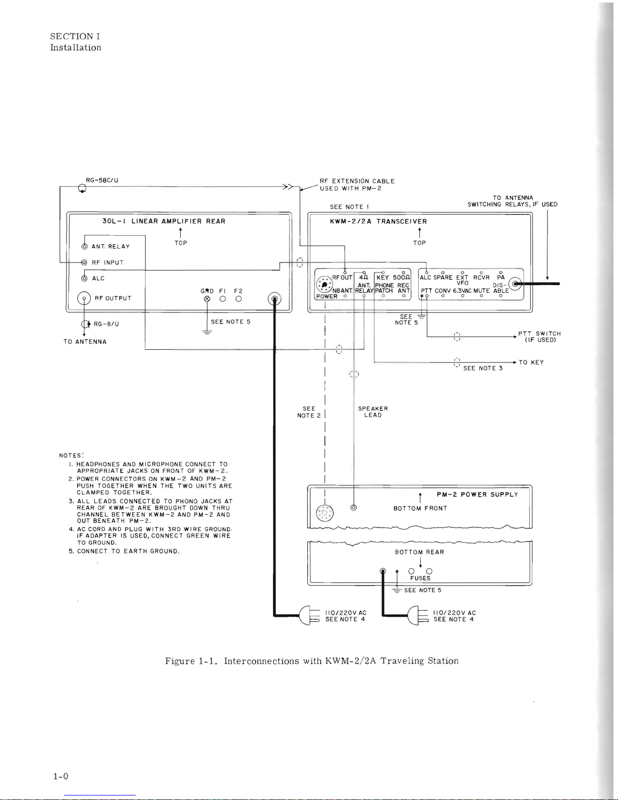
I.
HEADPHONES
AND
MICROPHONE
CONNECT
TO
APPROPRIATE
JACKS
ON
FRONT
OF
KWM-2
.
2. POWER
CONNECTORS
ON
KWM
-2
AND
PM-
2
PUSH
TOGETHER
WHEN
THE
TWO
UNITS
ARE
CLAMPED
TOGETHER.
3.
ALL
LEADS
CONNECTED
TO PHONO
JACKS
AT
REAR
OF
KWM-2
ARE
BROUGHT
DOWN
THRU
CHANNEL
BETWEEN
KWM-2
AND
PM-2
AND
OUT
BENEATH
PM-2.
4.
AC
CORD
AND
PLUG
WITH
3RD
WIRE
GROUND .
IF
ADAPTER
IS
USED,
CONNECT
GREEN
WIRE
TO GROUND.
5.
CONNECT
TO
EARTH
GROUND.
I
,-,
'-'
USED
WITH
PM-2
SEE
NOTE
I
KWM-212A
TRANSCEIVER
I
0
.
R
FOt,.
W
~Y
508n
:
_:
ANT.
PHONE
REC
'.
NBANT. RELAY
PATCH
ANT
PO
WER
0 0 0
I
1
TOP
I
I
i
SEE
~
NOTE 5
I ,-
TO ANTENNA
SWITCHING RELAYS, IF
I '-'
I
I
I
L----
-----i-'-i-'
-------+
TO
KEY
'-'
SEE
NOTE
3
N~~~
2 I
I
I
I
I
I
I
I
@
SPEAKER
LEAD
PM-2
POWER
SUPPLY
BOTTOM
FRONT
BOTTOM
REAR
~
r
oo
FUSES
~
SEE
NOTE 5
~
II01220VAC
~
IIO/220V
AC
USED
~
SEE
NOTE
4
~
SEE
NOTE
4
Figure
1-1.
Interconnections
with KWM-2/
2A
Traveling
Station
1-0
SECTION
I
Installation
SECTION I
INSTALLATION
.1
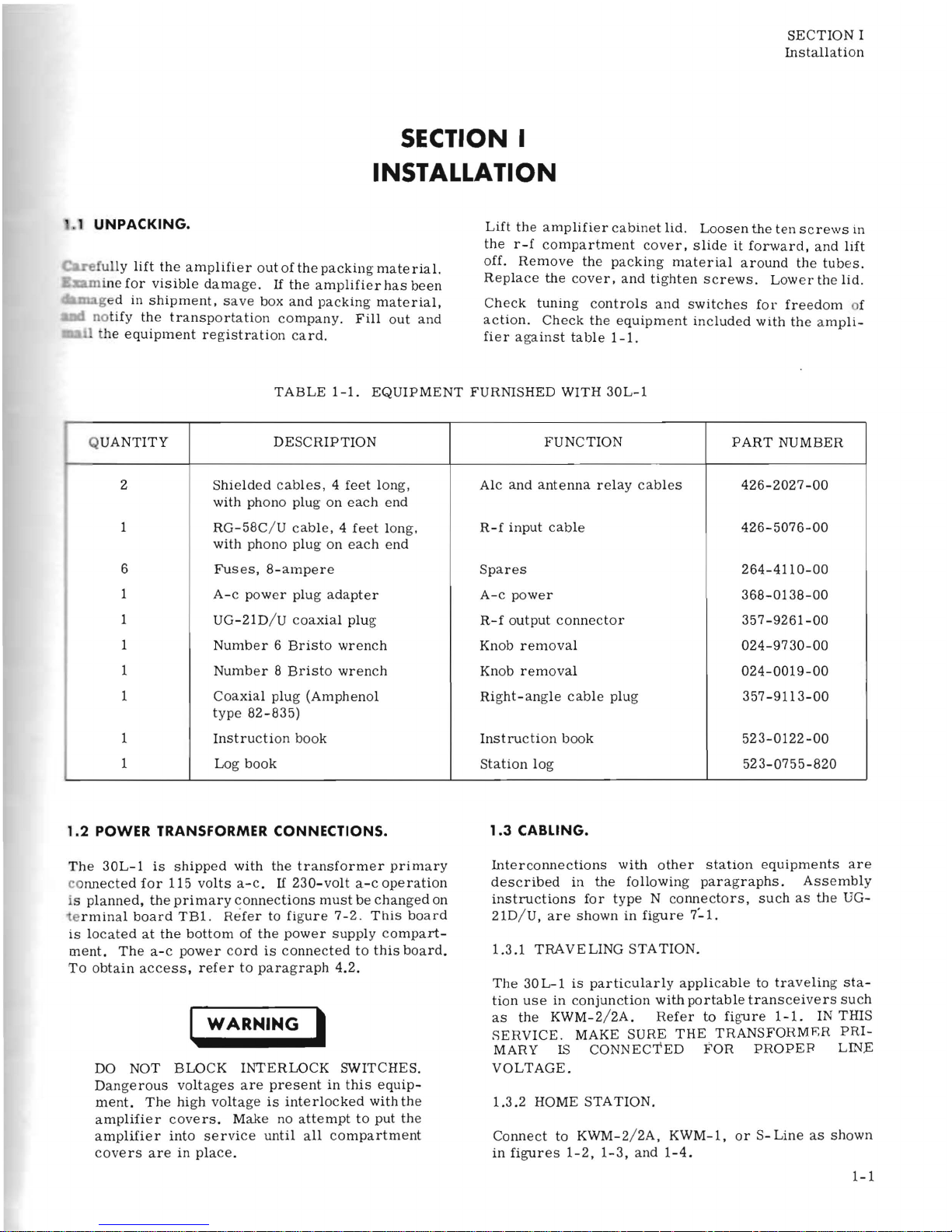
UNPACKING.
elully
lift
the
amplifier
out
of
the
packing
mate
rial.
i
ne
for
visible
damag
e .
If
the
amplifier
has
been
ged in
shipment,
save
box
and
packing
material,
no
tify
the
transportation
company.
Fill
out
and
he
equipment
registration
card.
Lift
the
amplifier
cabinet
lid. Loosen
the ten
screws
in
the
r-f
compartment
cover,
slide
it
forward,
and
lift
off.
Remove
the
packing
material
around
the
tubes.
Replace
the
cover,
and
tighten Screws.
Lower
the
lid.
Check
tuning
controls
and
switches
for
freedom
of
action.
Check
the
equipment
included
with
the
ampli-
fier
against
table
1-1.
TABLE
1-1.
EQUIPMENT
FURNISHED WITH
30L-1
Q
UANTITY
2
DESCRIPTION
Shielded
cab
les , 4
feet
lon
g,
with
phono
plug
on
each
end
FUNCTION
Alc
and
antenna
relay
cables
PART
NUMBER
426-2027-00
1
RG-58C
/ U
cable, 4 feet
long.
with
phono
plug
on
each
end
R-f
input
cable
426-5076-00
6
Fuses,
8-ampere
Spares
264-411
0-00
1
A-c
power
plug
adapter
A-c
power
368-0138-00
1
UG-21D
/ U
coaxial plug
R-f
output
connector
357-9261-00
1
Number 6 Bristo
wrench
Knob
removal
024-9730-00
1
Number 8 Bristo
wrench
Knob
removal
024-0019-00
1
Coaxial
plug
(Amphenol
type
82-835)
Right-angle
cable
plug
357-9113-00
1
Instruction
book
Instruction
book
523-0122-00
1
Log
book
Station
log
523-0755-820
1.2
POWER TRANSFORMER CONNECTIONS.
The
30L-1
is
shipped
with
the
transformer
primary
co
nnected
for
115
volts
a-c.
If
230-volt
a-c
operation
is
planned,
the
primary
connections
must
be
changed
on
e
rminal
board
TB1.
Refer
to
figure 7-2.
This
board
is loca
ted
at
the
bottom
of
the
power
supply
compart-
ment.
The
a-c
power
cord
is
connected
to
this
board.
To
obtain
access,
refer
to
paragraph
4.2.
WARNING
I
DO
NOT
BLOCK
INTERLOCK
SWITCHES.
Dangerous
voltages
are
present
in
this
equip-
ment.
The
high
voltage
is
interlocked
with
the
amplifier
covers.
Make
no
attempt
to
put
the
amplifier
into
service
until
all
compartment
covers
are
in
place.
1.3
CABLING.
Interconnections
with
other
station
equipments
are
described
in
the
following
paragraphs.
Assembly
instructions
for
type N connectors,
such
as
the
UG-
21D/
U,
are
shown
in
figure
7:'1.
1.3.1
TRAVELING
STATION.
The
30
L-1
is
particularly
applicab
le
to
traveling sta-
tion
use
in
conjunction
with
portable
transceivers
such
as
the
KWM-2
/ 2A.
Refer
to
figure
1-1.
IN THIS
SERV
ICE.
MAKE SURE
THE
TRANSFORMRR PRI-
MARY
IS
CONNECTED
FOR
PROPEB
LINE
VOLTAGE
.
1.3.2
HOME
STATION.
Connect
to KWM-2/ 2A,
KWM-1,
or S-Line
as
shown
in
figures
1-2, 1-3,
and
1-4.
1-1
SECTION
I
Installation
, ,
30L-1
ANT.
RELAY
-@
RF INPUT
~ALC
CV
RF
OUTPUT
RG-S/U
CAUT I
ON
BE SURE
KWM-2
IS PLUGGED
INTO
516F-2
BEFORE PLUGGING
5
16F-2
INTO
AC
LINE.
',.I
RG-5SC/U
GND
F I
F2
~
0 0
SEE NOTE 6
~
I.,!
516F-2
'-'
SHIELDED
WIRES
,-,
-
SEE NOTE I
KWM-2
EX~
POWER
I
SEE
NOTE
~
~
RF
r7
n
K~Y50~
[: °
_6..
;~
ALC
SPARE
EXT
RCVR
PA
-
OUT
ANT.
PHONE
REC
PTT
CONV6V{~CMUTE
DISABLE
NBANT
RE~
P
ATCH
ANT
POWER
° °
9
co
· 0 °
ANTSW
I: :
I
,-
,
, ,
""O"RG-5S
/U
I
RG-S
/ U
~
qDIRECTIO
NALP.
_~_
COUPLER
6
.~
V
TO
50
OHM
ANT.
(
PWR)
312B-5
E
X~FC
(OSCSIG)
AC
SEE NOTE I
D--
r
OUT
O .
.?
IN 4
0
n
~jfPHONE
ANTI-VOXAUDIO
IN
LI NE
VOX
BAL PHONE
(5)
pr,.A~CH
Q
OUT
[
ooooo[
NOTES '
"
TWISTED
PAIR
P HONE
FUSE
0
(!)
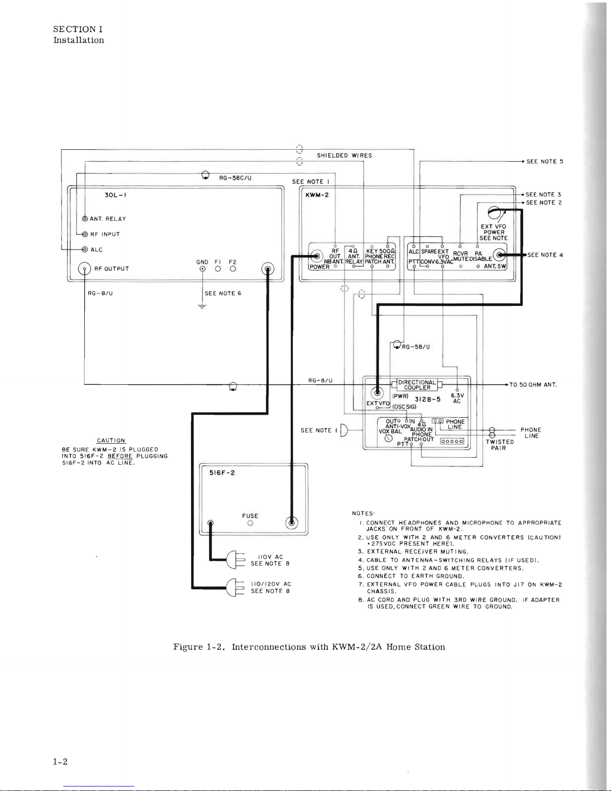
I CONNECT
HEADPHONES
AND MICROPHONE
TO
AP
JAC
KS · ON
FR ONT
OF
KWM-2
.
4
I
IOV
AC
SEE NOTE B
I
IOll20V
AC
SEE
NOTE
S
2.
USE ONLY WITH 2 AND 6 ME
TE R CONVERTERS
'275VDC
PRESENT
HEREL
3.
EXTERNAL
RECEIVER
MUTING
.
4.
CABLE
TO
ANTENNA-SWITCHING
RELAYS
(IF
US
EDI.
5.
USE ONLY
WITH
2 AND 6
METER
CONVERTERS.
6 .
CO
NNECT
TO
EARTH
GROUND.
7.
EXTERNAL
VFO
POWER
CABLE
PLUGS
INTO
JI7
CH
ASSIS.
B.
AC
CORD
AND PLUG
WITH
3RD
WIRE
GROUND. IF ADAPTER
IS
USED,CONNECT
GREEN
WIRE
TO GROUND.
,
SEE NOTE 5
SEE NOTE 3
SEE NOTE 2
SEE NOTE 4
LINE
PROPR lATE
(CAUTION
I
ON
KWM-2
Figure
1-2.
Interconnections
with
KWM-2/2A
Home
Station
1-2
SECTION
I
Insta
lla
tion
o
RG
8/U
TO
SO
OHM
ANT
.
KWM-I
SEE
NOTE I
30L-1
LINEAR
AMPLIFIER
~
ANT.
RELAY
~
RF
INPUT
J6 J7
~
GND FI
F2
~
RF
OUTPUT
[j]
[41:
o 0
'--A----<-
TO
KEY
EARTH
GROUND
~
RG-58
C1U
.
500
OHM
INPUT
FROM PHONE PATCH
IiF
USEDI
~
~
II
Q
~
500
OHM
OUTPUT
TO PHONE PATCH
(IF
USED)
~
I 4
OHM
SPEAKER
1I0/220V AC
SEE NOTE 4
~
P4
/ Q ) TO
AUXILIARY
RECEIVER
(IF
USED)
RG-S8/U
(SHORT
COAX)
,,~
_____
ADD
THIS
BREAKOUT WIRE TO CABLE IF
KWM-I
SERIAL
NUMBER
IS
BELOW 861. SEE NOTE 3 AND
DETAIL
A.
SEE
~
N0
TE
-3
CAU
TION (SEE NOTE S)
TO ANT.
RELAY
2
JACK
ON
30L-1
10K
j PHONO PLUG
KWM-I
TBI-8
J5-20
sw
POWER
C
ABLE
9
C206
I 10K OHMS
IOMA
=
COIL
RELAY
NOTES
'
COLLINS
PIN
9721 34600
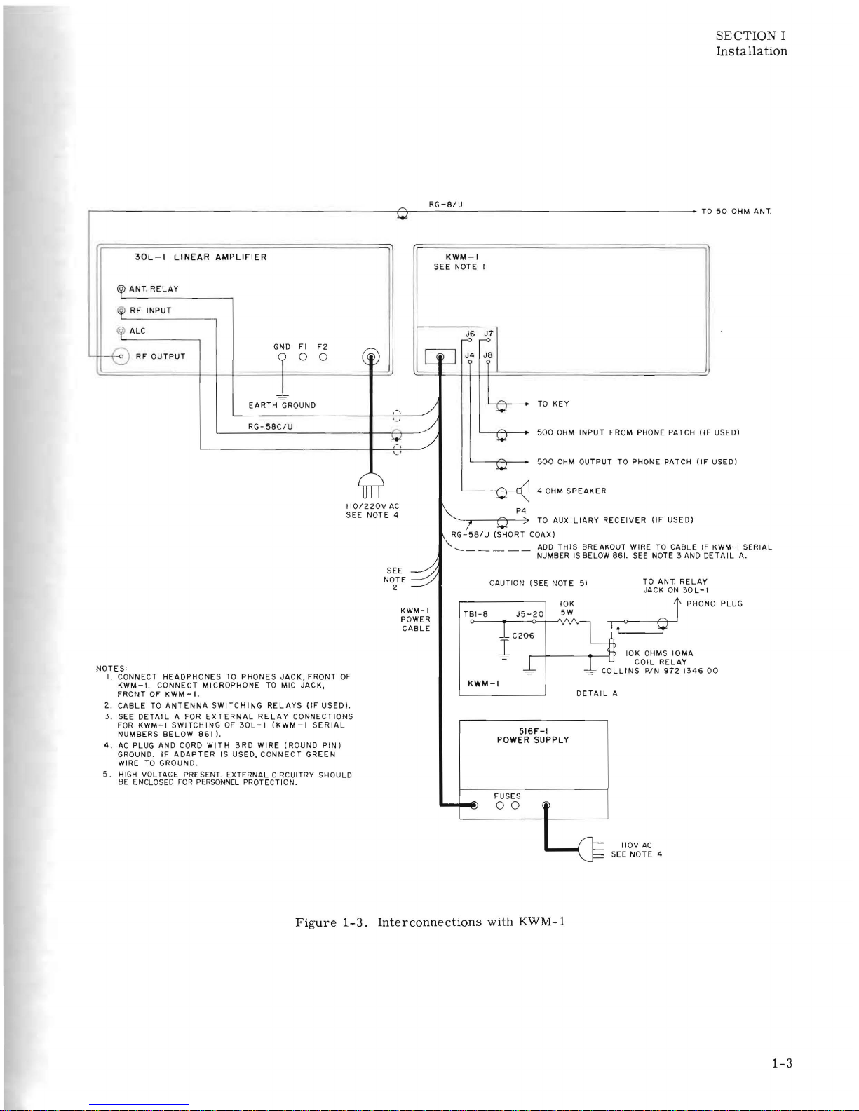
I.
CONNECT
HEADPHONES
TO
PHONES
JACK,
FRONT
OF
KWM-1.
CONNECT
MICROPHONE
TO MIC
JACK,
KWM-I
FRONT
OF
KWM-I.
DETAIL
A
2.
CA8LE
TO
ANTENNA
SWITCHING
RELA
YS
(IF
USED).
3.
SEE
DETAI
L A FOR
EXTERNAL
RE
LAY
CONNECTIONS
FOR
KWM-I
SWITCHING
OF
30L-1
(KWM-I
SERIAL
NUMBERS
BELOW
8611.
516F-1
POWER SUPPLY
4.
AC
PLUG AND CORD
WITH
3RD
WIRE
(ROUND
PINI
GROUND.
IF
ADAPTER
IS USED,
CONNECT
GREEN
WIRE TO
GROUND.
S . HIGH VOLTAGE
PRE
SENT. EXTERNAL CIRCUITRY SHOULD
BE
ENCLOSED
FOR
PERSONNEL
PROTECTION.
FUSES
~
00
4
IIOV
AC
SEE
NOTE
4
Figure
1-3.
Interconnections
with
KWM-1
1-3
 Loading...