

Collins 300G Instruction Book
INSTRUCTION
FOR
3oäG
BOOK
AM
BROADCAST
TRANSMITTER
COLLINS
CEDAR
RADIO
RAPIDS,
COMPANY
IOWA
Y
WARNING
r
OPERATION
VIOLVES
ARE
SONNEL
ALL
THE`;L7'SE'O'
DANGERO.USITO
SHOULD tT,
THE SAFETY
NOT CHANGE
MENTS
INSIDE
VOLTAGE
UPON DOOR
BUT ALWAYS
MENT
SUPPLY
AND
CIRCUIT.
GROUND CIRCUITS
THEM.
Since the .uses
to
ous
eration
by
-- fires must
í
personnel
human.
of
these
the radio .transmitting
instructions,
be carefully
during the adjustment
the equipment.
The
major
metal
cabinet enclosures,
which
are
generally fitted
switches which
the cabinets
Interlocks
panels within
will not
cause interlocks
mfr..,
OF
, IS g.QUIFMENT;-
I
t.TtES LISTED
TUBES
.EQUIPMENT
SUPPLY
SWITCHES
SHUT DOWN
OPEN MAIN
ALWAYS
of iìigh vdliáges
life is.
necessary
certain
-
portions
of the
remove
when
.ácces5 doors
are also
provided on
the cabinets.
;.
atiN.
I.íIFE'
ON. DO NOT
PRIOR
sm.t
observed
provided
dangerous
Other panels,
to function
LTÄGES
E
Or
'
L MMES
.ATING P'ER.-
OBSERVE
BELOW.
OR MAKE ADJUST-
-
WITH
DEPEND
FOR
PROTECTION
POWER
SWITCH IN
DISCHARGE
TO TOUCHING
'wkriëh
to the
are
successful
equipment
precautionary
the
by
and
equipment
operating
operation
are within
with access doors
with
safety
interlock
voltages
are
open.
certain
removable
if removed,
and
will thereby
;
IN-
WH
GH;
DO
HIGH
EQUIP
PO4t
EIL7
AND
danger-
op-
covered
meas-
within
of
allow
access to circuits
to human life.
AWAY
KEEP
Under no
within
a cabinet
supply line
or handle any portion
is
external
-q
nets;
even for
portion
supplied
to the
or to
testing purposes
of the
-
- -'
`
ble in testing
ance checks
at various
the
to
DON'T
transmitter
SERVICE
Under no
within
justing
sistance
DON'T TAMPER
Door
cabinet
a
the
of another
or safety
removed
placed
voltages
upon
from
FROM LIVE
circumstances
with interlocked
switches
with
power;
cabinets
apply
cabinet
circuits,
rather
points when
OR
circumstances
for the
equipment
WITH
interlock
or
short
circuited,
the
interlock
the
equipment.
carrying
CIRCUITS
voltages dangerous
should any person
gates
while power
to
the equipment
of
exposed equipment which
or to connect any apparatus
to
circuits within the
high
voltages
while
is
removed. Whenever
to
the equipment
any non -interlocked
make continuity
than
directly checking
any
high voltage is
circuits.
ADJUST
ALONE
should any person
purpose of
without
person
INTERLOCKS
capable of
switches
servicing
the
presence
rendering aid.
should
nor should
switches for
reach
are closed;
cabi-
feasi-
and resist-
voltage
applied
reach
or ad-
as-
or
be
not
reliance
be
removing
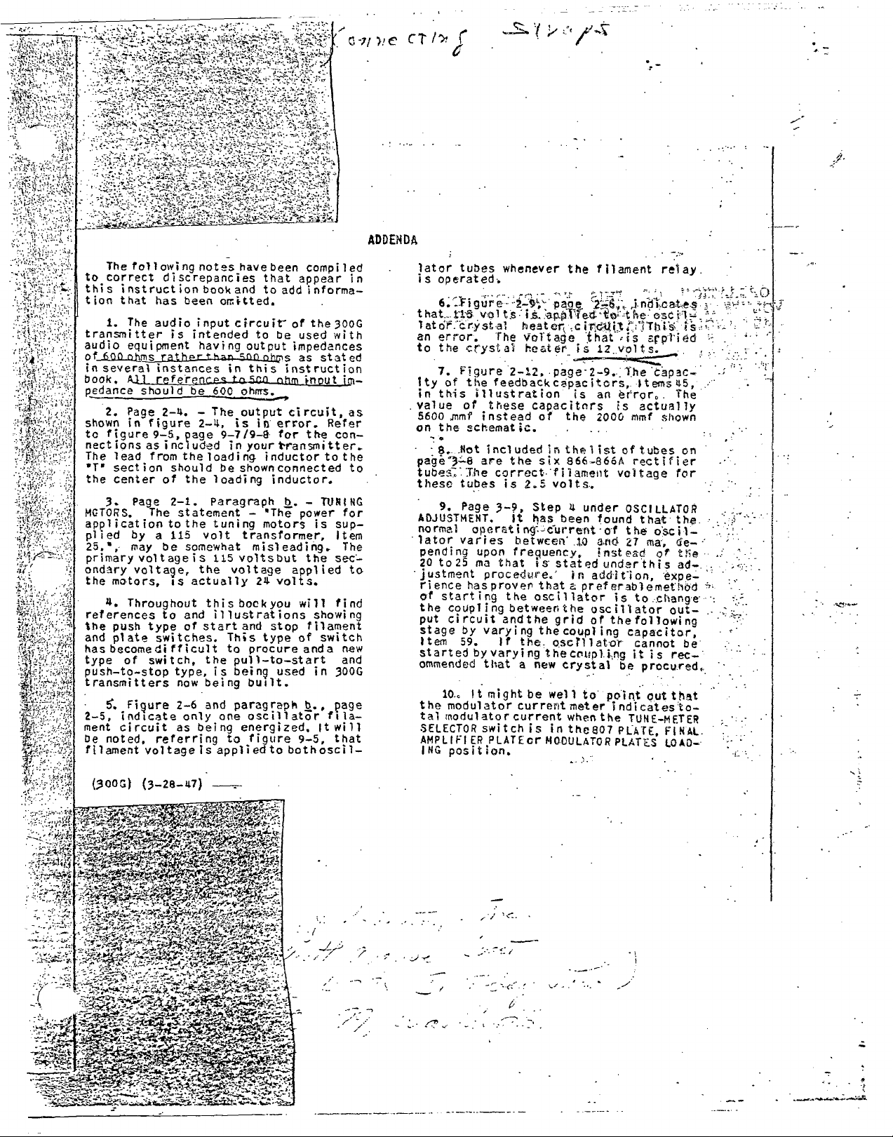
ADD
EN DA
The following
to
correct
this
instruction
tion that
1. The
transmitter
audio
60_0
of
fa several instances
book.
pedance should
2. Page 2-4. - The output
shown
to figure
nect
The
'T. section
the
3.
MOTORS.
application
plied
25.', may
primary volt age
ondary voltage, the voltage
the
motors,
4.
has been omitted.
audio
equipment having
ohms
A.U.....mtareac.es..1415cal_aten.as_unl
in figure
9-5,
ions
as included
lead from
center of the
Page
The statement -
by a 115 volt transformer,
Throughout
references
the push type
and plate
has
becomecli fficult
type
push-to-stop
transmitters
2-5,
ment
be
noted,
filament
switches.
of switch,
Figure
indicate only
circuit as
referring
voltage is applied to
notes
have
discrepancies
book
been compiled
that
and
to
input circuir of
is intended
rathe_r_t_hari.aanohms
to
output
in this
be 600
page 9-719-8 for the con-
the
should
ohms.
2-4,
is in error. Refer
in your
loading inductor to
shownconnected
be
loading inductor.
Paragraph b. -
2-1.
to the tuning
be somewhat misleading.
i s 115 volts but the sec-
is actually
this bockyou
illustrations showing
and
to
start
of
type,
now
2-6 and paragraph b.,
This
to
the pull-to-start and
is
being
one oscillator
being energized.
to figure
The power for
motors is sup-
24 volts.
and stop filament
type of switch
procure
being
built.
appear
add informa-
in
the 300G
be used with
impedances
as stated
instruction
ut
circuit,
transmitter.
as
the
to
TUNING
Item
The
applied to
find
will
new
anda
used
in 300G
page
fila-
It will
9-5, that
bothoscil-
-
later tubes
is operated.
6..rigure
that_
11.5
latör.crystal
an error.
to
the
7. Figure
of the
ity
in this illustration
value of these
5600 ;milt instead of
on the schematic.
7 .
- Et. _Not
pagi3--;-8 are the six 866-866A
tube. The correct
these tubes is 2.5 volts.
9.
ADJUSTMENT.
normal
lator
pending
25 ma that
20 to
justment
rience
of starting the oscillator
the
coupling
put circuit
stage
Item
started by varying
ommended
10.. It might be well
the
modulator current
tal
modulator
SELECTOR
AMPLIFI
ING
position.
whenever
vol
t5 'oppflexe
The
crystal
2-12, page-2-9.
feedbackcapacitors,
included
pane, rin-cf)..cateS
heater
Voltage
heater is
capacitors
the
. .
in thelist
filament
Page
olleratinT-Current
varies
upon
procedure.'
has
by
varying
59.
that
Step 4 under
It has
betwcen
freguency
is stated
prover
that
between the
andthe
the
If the
a new
been
grid
coupl
oscrliator
the
crystal
current
switch
ER PLATE
is in the807
cr
MODULATOR
the filament
.circ4itr.'11-hiS,
that
12 volts.
is
an
2000 mmf shown
found
-of the
and
.10
. instead or
under this
In additIon,
a pref erablemethód
oscillator
of
the
ing
cntipl
',rig
to
point out
meter
when
indicatesto-
the
relay
tle ost
iS
arplied
is
The'capac-
ltems45,
error.
Es actually
of tubes
voltage for
OSCILLATOR
27
is
capacitor,
be
TUNE-METER
PLATE,
PLATES
The
rectifier
on
that the _
oscil-
ma,
de-
trie
ad-
expe-
to
change
out-
following
cannot
it
be
is
rec-
procured.
that
FINAL.
LOAD-
-
,
-;
, .
:
t
-,,t.4.,-
-'*--
(OOG) (3-28-47)
.,..t'....-_.--"--..e-4.
,
r.,:'S;.......'
Cfri.j..-`4'....;:.*
'-
.e. .t.
' ::*ei. '''.,.
. "::,: f.;'=_,:.."-.-
-...:::,;:,,', ...J.
,t. :-_-_-,
-,..4-'*'Tr-7.?
,,,-...t-------.:1Agt.,...z_*.....-
.:;,-,:0,4
.... ?",,
,
-...,',....40
i:. "';',.-4...k..,;11-2-1-40.,`-
. "..:..- :,-4743r-:,;+0,......,14,.
_ .
-,-r.,4::-.'f:`,1;:Z.-,s=i4.=,,C,.- ,,_ _
'n
..,
.- :
-441V..1'4,..4"r-
,":-..4?.!fX..11(1.3.?..,:,.
V.!'
1-
S....-4":
--..7,
.;-;,,, viu":-;,:
-
www.americanradiohistory.com
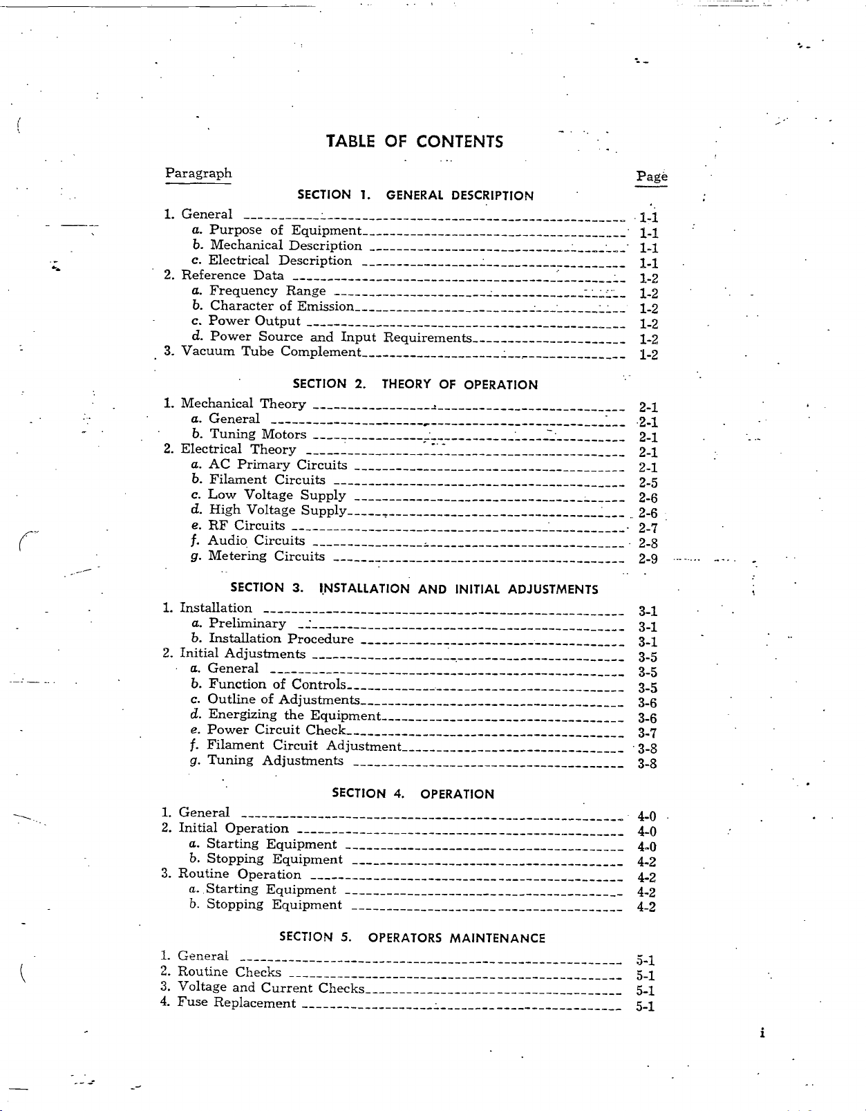
TABLE OF
CONTENTS
Paragraph
SECTION
1.
General
a. Purpose
b. Mechanical
c.
Electrical
2.
Reference Data
a. Frequency
b.
Character
c. Power
cl.
Power
3.
Vacuum Tube Complement
1. Mechanical
a.
General
b. Tuning
2.
Electrical
a. AC
b. Filament
c.
Low
d. High
e.
RF
f. Audio
g. Metering
of Equipment
Description
Description
Range
of Emission
Output
Source
and Input
SECTION
Theory
Motors
Theory
Primary
Circuits
Circuits
Voltage
Voltage
Supply
Supply
Circuits 2 -7
Circuits
Circuits
1. GENERAL
Requirements
2. THEORY
DESCRIPTION
OF OPERATION
s
Page
14
14
1-1
1-1
1-2
1-2
1-2
1-2
1-2
1-2
24
2 -1
2 -1
2 -1
2 -1
2 -5
2 -6
2 -6
2 -8
2 -9
SECTION
1.
Installation
a. Preliminary
b. Installation
2.
Initial Adjustments
a. General
b. Function
c. Outline of
d. Energizing
e. Power
f. Filament
g. Tuning
1.
General
2. Initial
Circuit
Operation
a. Starting
b. Stopping
3.
Routine
a.
b.
1.
General
2. Routine
3. Voltage
4.
Fuse
Operation
Starting
Stopping
Checks
and
Replacement
3.
INSTALLATION
Procedure
of Controls
Adjustments
the
Equipment
Check 3 -7
Circuit Adjustment
Adjustments
SECTION
Equipment
Equipment
Equipment
Equipment
SECTION
Current
5.
Checks 5 -1
AND INITIAL
4.
OPERATION
OPERATORS
ADJUSTMENTS
MAINTENANCE
3 -1
3 -1
3 -1
3 -5
3 -5
3 -5
3 -6
3 -6
- 3
3 -8
4 -0
4 -0
4 -0
4 -2
4 -2
4 -2
4 -2
5 -1
5 -1
5 -1
-8
www.americanradiohistory.com
i
Paragraph
5.
Circuit
6.
Tube Replacement
7. Room
Breakers
Temperature
Page
5-1
5-3
1. Cleaning
a.
Transmitter
-
b. Air Filter
2, Lubrication
a. Ventilating
b. Tuning
3. Routine
a. Tube
b. Mechanical
1. General
2. Trouble
a.
b.
C. Power
Checks
Check
Shooting
Tube Failure
Isolating
d. Distortion
e. Parasitic
f.
Power
- g.
Failure
h.. Ventilating
i. Tuning Motors
3. Servicing
Code
Color
SECTION
6. PREVENTATIVE
General
Blower
Motors
and
Inspection
SECTION
the
Trouble
Supply
Troubles
Oscillations
Amplifier
of
Stage
Oscillator
Blower
the Equipment
SECTION
8. TABLE OF REPLACEABLE
Assemblies
7.
CORRECTIVE
not
Neutralized
Unit
MAINTENANCE
6-0
6-0
6-0
6-0
6-0
6-0
6-0
6-0
6-0
MAINTENANCE
7-1
7-1
7-1
7-1
7-1
7-2
7-2
7-2
7-2
7-2
7-2
7-3
PARTS
8-10
SECTION
9.
MISCELLANEOUS
PHOTOGRAPHS
AND
DRAWINGS
www.americanradiohistory.com
GUARANTEE
This equipment is guaranteed against defects in
material, workmanship or manufacture,
for a pe-
riod of one year from the date of delivery. Our
obligation under this guarantee is limited to
.ing or replacing any item which shall prove, by our
repair-
examination, to be thus defective, provided the item
is returned to the factory .for inspection with all
transportation charges paid., _Before returning any
item believed to be of defective material, workman-
ship or manufacture, a
mitted to the company giving exact information
to the nature of the defect. The information
include,
material
of parts. Upon receipt
pany, a returned equipment tag
to the shipper without
EQUIPMENT
SHIPMENTS
TION WILL
in as much detail as possible, all subject
listed under instructions for replacement
TAG MUST ACCOMPANY ALL
OF DEFECTIVE
BE TAKEN ON
RETURNED TO THE COMPANY UNLESS
SHIPMENT INCLUDES THE
detailed report must be sub-
of the report by the com-
will be forwarded
delay. THE RETURNED
PARTS.
NO AC-
ANY EQUIPMENT
RETURN TAG.
COLLINS
RADIO COMPANY
as
shall
THE
iv
,-.....,
www.americanradiohistory.com

LIST
OF
ILLUSTRATIONS
. Figure
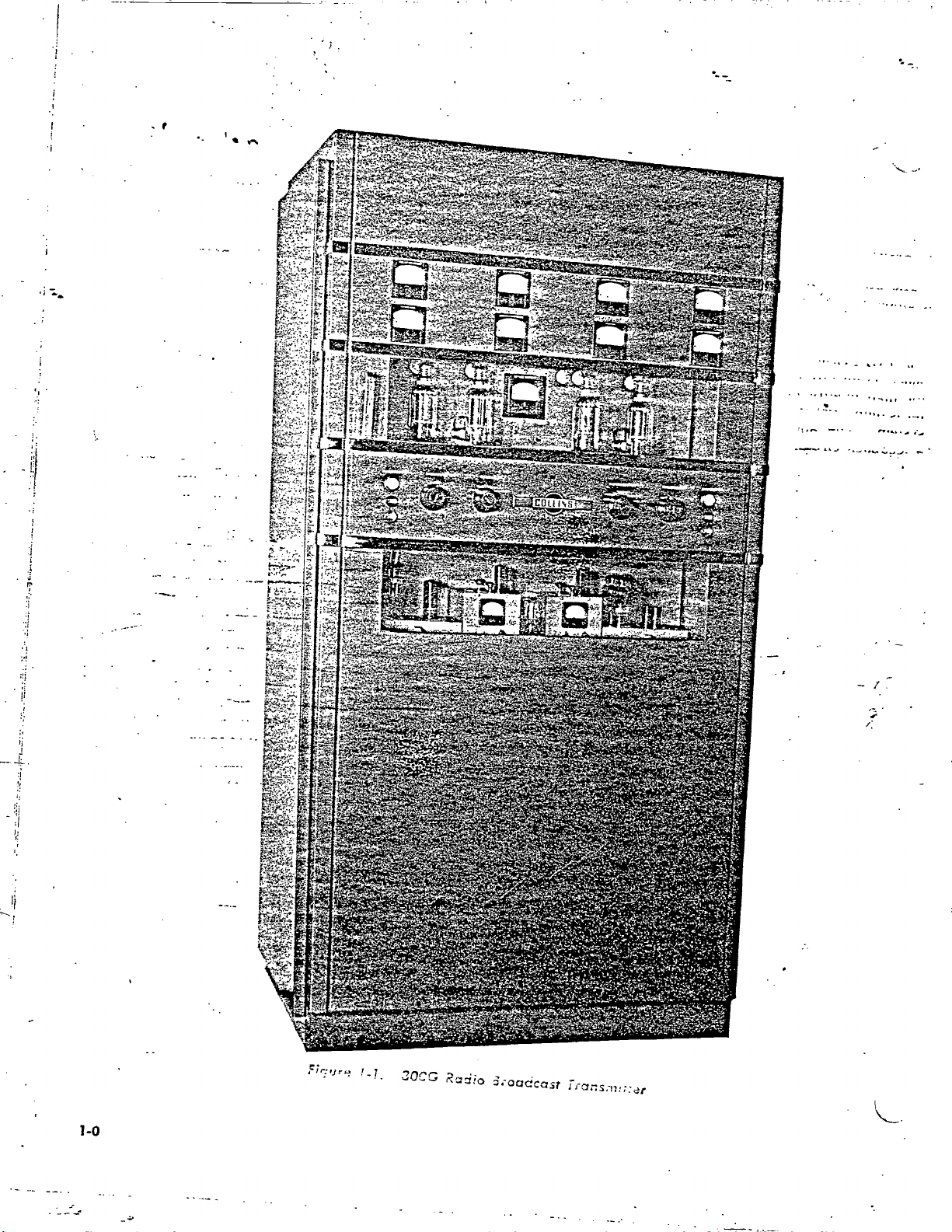
1 -1 300G Radio
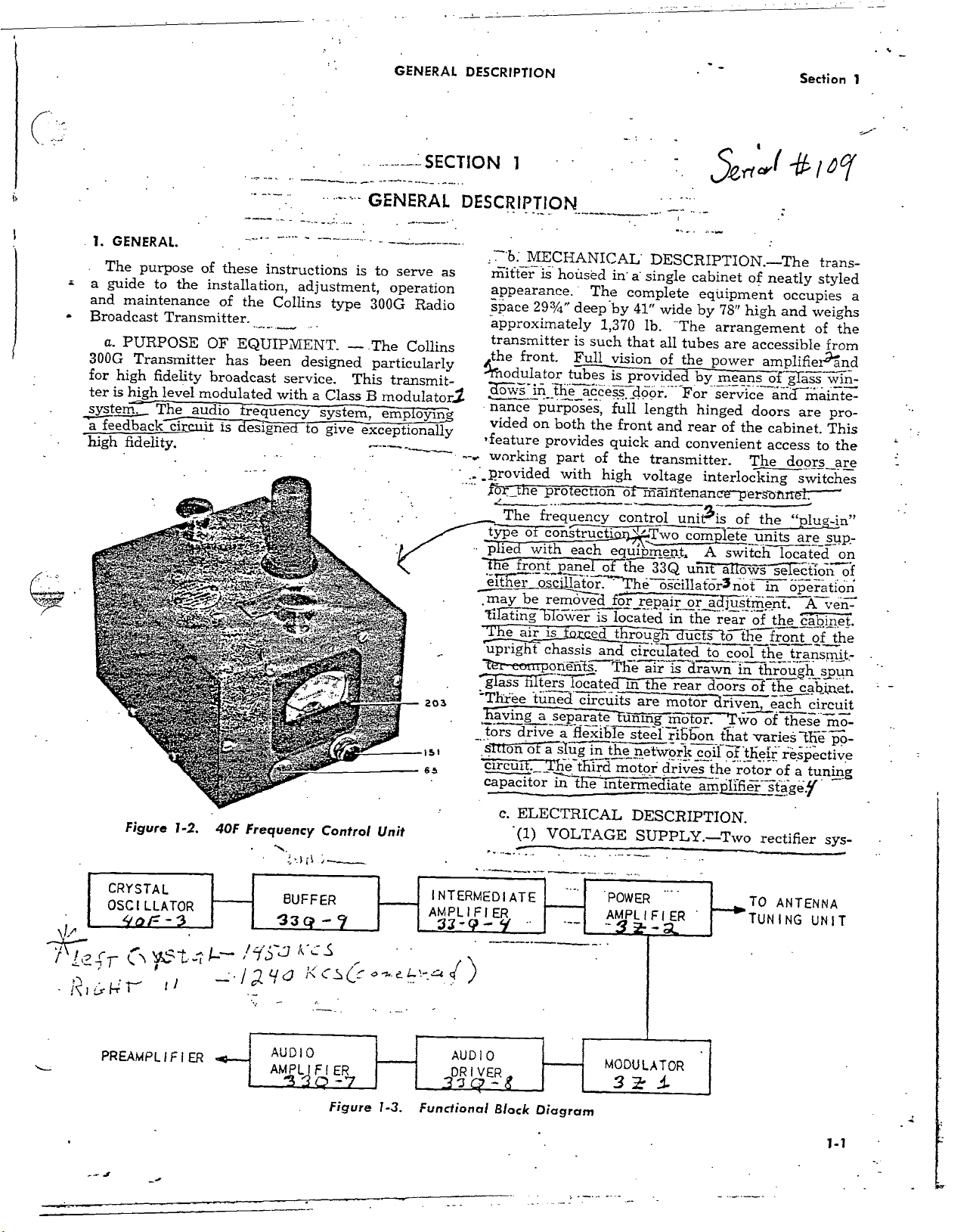
1 -2 40F
1 -3
2 -1 Tuning
2 -2
2 -3 300G
2 -4 Motor
2 -5
2 -6 Filament
2 -7 Low
2 -8
2 -9
2 -10 40F
2 -11
2 -12 Audio Driver
2 -13 Metering
3 -1
3 -2 300G
3 -3
3 -4 Power Level
3 -5 Test Meter
3 -6
3 -7 Tuning Control
3 -8
3 -9
3 -10
3 -11 300G Transmitter
3 -12 RF Tuning
4 -1
5 -1
7 -1 Door
7 -2
8 -1
8 -2 Audio Frequency
9 -1
9 -2 300G
9 -3
9 -4 65Q -30
9 -5
9 -6 38N
9 -7 300G
9 -8 300G Simplified
Frequency
Functional
300G Transmitter
Transmitter
Driven
Power
Voltage
High
Voltage
Oscillator Circuit
Frequency
297 Crystal
Floor
Plan
Transmitter
300G Transmitter
Tune Meter
Block
Block
Diagram
Diagram
Block Diagram
300G Transmitter
300G
Transmitter
Panel- Inside
300G Transmitter
Audio Frequency
100
Watt
250 Watt
300G Transmitter
Transmitter
Transformer
1100N
Vertical
-1
Control
Complete
Title
Broadcast
Block
Motor
Control
Circuits
Rectifier
Rectifier
Oven (503
Circuits
for
Switch (503
Switch
Selector
Curves (503
Operation
Operation
Winding Data
Cable
Schematic
Assembly
Circuits
and Modulator
Chassis Cabling
and
Transmitter
Control
Unit (6978)
Diagram
-Rear
Open View (9758)
-Front
(503
Circuits
(503
(503
2268
Circuit (503
Circuit
Schematic
Control
Unit -open
2267
(503 2272
Installation
-Top Rear
Bottom
-
2258
(503
Switch
Switch (503
Adjustments
of
Power
of
Panel
of
Control
-Front
2266 002)
-Front
-Front
(Inst
(503
Open View
2270
(503 2263
002)
(508 0899
Rear View
2262 001)
(503 2261
Circuit Checks
Open
View Closed
View
(510
0320
00)
800X)
2269
002)
(9757)
003)
2259
001)
002)
2265
001)
(503
2264 001)
001)
View (6779)
- 2 -8
Schematic (503
003)
20)
2271 003)
View (9761)
(9762)
001)
001)
2260
001)
Functions
View (9757)
Open
(510 0320
(6973)
00)
View (9764) 7-4
-Rear
Response
Response
- Bottom
-Top
Schematic
Schematic
Meter
View
Open
and
Distortion
and
Distortion
Front
Front
View (9763)
(503 2273 004)
(508
0597
Schematic
Door
Schematic (508
(508 0145 40)
(508 0206
(9758)
View
10)
30)
Curves for
Curves
(9760)
(508
0194 30)
for
0143 50)
Page
1 -0
1 -1
1 -1
2 -1
2 -2
2 -3
2 -4
2 -4
2 -5
2 -5
2 -6
2 -6
2 -7
2 -9
2 -9
3 -1
3 -2
.3
-4
3 -5
3 -5
3 -5
3 -6
3 -6
3 -7
3 -9
3 -10
3 -12
4 -1
5 -2
7 -5
8 -11
.
8 -12
9 -1
9 -2
9 -4
9 -3
9 -5
9-7/9-8
9 -9
9 -11 '9 -12
9-13.'9-14
www.americanradiohistory.com
iii
REPLACEMENT OF PARTS
In case
sired,
pany.
failure and must
(A) Date of delivery of equipment.
(B) Date placed
(C) Number of hours in service.
(D) Part number of item. .
(E) Item number (obtain
(F) Type
.
(G) Serial number of unit.
(H) Serial
a replacement under
a full report must
This report shall cover
include the following
in service.
matic Diagram). _
number of uriit from
moved.
number of the complete
(I) Nature of failure.
(J) Cause of failure.
(K) Remarks.
the guarantee is de-
be submitted
from Parts List or Sche-
to the com-
all details of the
information:
which part is re-
.......______
equipment.
_
_
.......
When requisitioning
lowing information must be furnished:
(A) Quantity required.
(B) Part number of item. ..
(C) Item number (obtain from Parts List or
Schematic
(D) Type number of unit.
(E) Serial
(F) Serial number of equipment.
NOTE: Blank Service Report forms will be
found in the appendix of
number of unit.
replacement parts, the fol-
.
Diagram).
this instruction book.
- -
..._
-
.
At;
;Jr
44".. ,4-
20C.G
Radio
6.-oadcast
www.americanradiohistory.com
GENERAL
DESCRIPTION
Section
1
GENERAL.
1.
The
purpose
a guide
and
Broadcast
a.
300G Transmitter
for
ter is
system.
feedback-errs-flit
high
to
maintenance
PURPOSE
high
fidelity
high
fidelity.
of
the
Transmitter.
level
modulated
The audio
these
instructions
installation,
of the
OF
has
broadcast
is cgirgirja
Collins
EQUIPMENT.
been
with
requency
adjustment,
type
designed
service.
a Class
system,
to
give
----------SECTION
GENERAL
is
to
serve
operation
300G
Radio
-
The
Collins
particularly
This transmit-
B
modulator/
employing
exceptionally
203
1st
65
1
DESCRIPTION
"b: MECHANICAL'
as
mitter
appearance.
space
approximately
is
293/4"
transmitter
the
,the
front.
3ows
iñ
nance
vided
*feature
working
_._provided
_fife
type
..
pie
"iTe front_p
ewer
may
ti
the
The
of
with
be
á ng
e
air
purposes,
on
frequency
osc'llator.-
hTov
upright
Ter-
earnporiñf.'s
g astiis ters-ócated°in
awing
T oCi ñ
tuned
a
"Three
tors
s
circus.£_,
capacitor
housed
the
both
provides
part
with
protection
constructisx}
removed
is
chassis
separate
a
sÌug
Thethrd
Ti;-:
in
The
deep
by
1,370
is
such
Full
vision
tubes
is provided
áccés`s:
full
the
front
quick
of
the
high
control
each
equipment.
nel
óf the
fò_r_repair,
--
is located
e d t
and
The
circuits
flexible
inthe
motor
the
intermedIate
-
DESCRIPTION.
a single
complete
41"
lb.
that
door.
length
wide
The
all
tubes
of
the
For
and
rear
and
convenient
cabinet
equipment
by 78"
by
hinged
transmitter.
voltage
of
maintenance
unit5is
,Two
complete
33Q
uni
he
óscillatór3not
or
in the
roug
circulated
are
urn-
steel
network
air
is'drawn
the
rear
motor
mo or,
ribbon
drives
uclsh
coil
amp/
-The
of neatly
high
arrangement
are
accessible
power
service
interlocking
A
ádjústm_éñt
to
doors
driven
the
means
doors
of
the
The
pers
of
switch
a ows
rear
of the
thé
cool
-in
of the
wo
that
variestFF
óf -their
rotor
fier
amplifier°ánd
of -ggTass
and
cabinet.
access
timt.-
the
units
se7ëctioñ
in
front
the transmit
through
each
of these
of
stägëy
trans-
styled
occupies
and
weighs
of
the
from
win
maiote-
are pro-
This
to the
door_s_are
switches
"plug
-in'
are _s_up-
located
on
of
operation
A vën=
cabinet.
of
the
spun
cabinet.
circuit
mo-
pp-
respective
a tuning
a
-
*
-
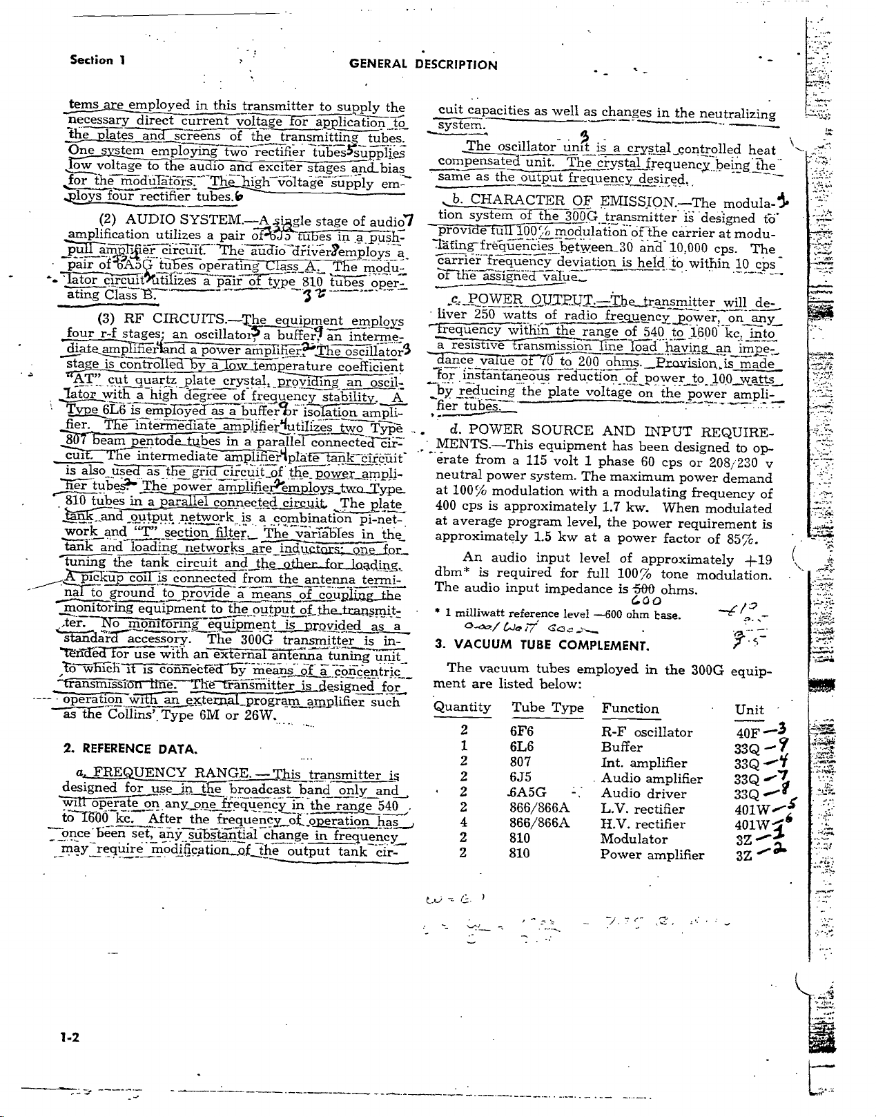
Figure
CRYSTAL
OSCILLATOR
5tr
r ,,~
f
`? /gyd
¡ t
!
PREAMPLIFIER
-
1 -2.
-3
,
!
40F
- ._
-
Frequency
,7
3
Control
s
Figure
c.
ELECTRICAL
Unit
-
.
1 -3.
Functional
www.americanradiohistory.com
(1)
Block
Diagram
VOLTAGE
DESCRIPTION.
SUPPLY.
-Two
rectifier
TO
ANTENNA
TUNING
sys-
UNIT
1 -1
Section
terns
necessary
the plates
One
Ìow
for
thé modiiTtörs."
_loys
amplification
pull
pair
-
lator
ating
four
diate
is
age
'AT"
lator
Type
fier.
8Ó7
cut ,
is
also
er
tubes?'
810
tubes
work
tank
tuning
pic
-f -ná7 to
m- o
bring
ter. -No
dar`r-accessory.
`téi déd
to W1i
' transmissiói
----
operation
REFERENCE
2.
a.
FREQUENCY
designed
wi
operat
to-I600
once
may
1
are
employed
direct
and
'stem
employing
voltage
(2)
àm
ofWAo
circuit')
CiasT 73.
(3) RF CIRCUITS.
four
AUDIO
7
to
rectifier
ër circuit.
r -f stages-
ampl
with
6L6 is
cam pentode
er
is
contro-lle-d
cut
quartz
a high
empToÿëd
T
íl-e iñtermëd'iate
in this
current
scieens_
the auTc
utilizes
tu :e_s_operating
itilizes
io
"`Thy
tubes.b
SYSTEM.
a pair
a pair
an
oscìllatoi?
d a power
byyemperature
plate
degree
as
_tubes
e intermediate
used
as
t íF e gril
Th
yower
in
a parallel connected
ö_ u tput
and "T"
and
loading
the
up coil is
ground
mont orf-
-for
use
1ch
it is coñnebtéd"bÿ
rtiñe-
w7.-fhán.
Collins',
for
ó
kc.
been
sset_,
require
network
section
networks
tank circuit
connected
to
provide
equipment to
iñg_equipment
The
with
adernar
an
The`trañsmitter
e teii
Type
6M
DATA.
RANGE.
use
in t
íf e- broadcast
n
any
one
A fter
the frequency
any
substantial
modlficátion_of
transmitter
voltage
of the
for
transmitting
twö` rectifier
and exciter
hig
vo
----A
ogle
of bJS`
fine
áuaiö-
driverrem
C`lass_A..
ó pe
-
he
equipment
a buffer,
ampli
crystal,
of frequency
a
ampl
in
ampií$ér`tplate
rcuit_of
filter.
and
the
a1_program
or
frequency
prove
bufferár
fier`(utilizes
a parallel
the_
circuit,
ís
a combination
The
yärT
áre_ind
the
o_ther
from
the
á means
output
is
300G
transmitter
antenna
m-e-án
_._òf
26W.
-This
in
of
change
the
output
GENERAL
to
supply
application
tubes.
tubessuppli-es
stages
age
tubes
810
3
and_bias
supply
stage of
in
a_push-
Th
lages
----
employs
an
interro
lo
m_ odu-
-_
Thé oscillatori
coefficient
ing
an
stability.
isolation
connecte
power
ampli-
two
Typé
tank
irciij-
ámpli-
tvwa_Type_
The
pi
bles
in
cioxs,._on
forloading-
antenna
offccoupflj
of
the_transmit-
provided
is
amplifier
transmitter
band
the range
o eration
in frequency
termi-
g_the
is
tuning
á bncentric
esigned
only
tank
the
to_
-'
em
audia
s a
oper
e,
oscil-
A
irl
plate
-net
-
the
or_
as a
in-
unit
for
such
is
and
540 .
DESCRIPTION
cuit capacities
`system.
The
oscillator
compensate
same
as
the
b.
CHARACTER
tion
system
prove
e
u
:läting-frëgúéñcies
carrierr-fi
Zit-the
_é. POWER_
liver
nrequency
a
resistive
ance
for
üency
assigned
250
watts
within
va
ue
in-stanta_
transmissióñ
_by reducing
fier
tubes.
f
d.
POWER
MENTS.
erate from
neutral
at
400
at
approximately
dbm
The
1
-This
a 115 volt
power
100%
modulation
cps
is approximately
average
An
* is
audio
milliwatt
program
audio
required
input impedance
reference
° m/ t.la ii Ga
3. VACUUM
The
vacuum
ment
are listed
Quantity
2
1
2
2
2
2
4
2
2
Tube
6F6
6L6
807
6J5
-6A5G
866/866A
866/866A
810
810
as well
unt is
unit.
The
output
o the
l00`,;ó
of70 to
eu_s
the
TUBE
300G transmitter
modulation-òf
between_30
deviation
value.
OUTPUT.-
of radio
the
reduction
plate
SOURCE
equipment
system.
level,
1.5 kw
input
for
level
c
COMPLEMENT.
tubes
below:
Type
as changes
a crystal
crystal
frequenc
OF E_
frequency
desired.
MISSION.
the carrier
'an-a-10,000
is
held
Theránsmitter
frequency_
range
200
The maximum
with
level
employed
of
540 to
Ine
load
ohms.__Prwision..is
of_power
voltage
I. phase
at a power
full
-600 ohm
on
_
...""
AND
a
1.7
INPUT
has
been
60
modulating
kw.
the
power
of
approximately
100%
is
&BfJ
Goo
in
Function
R -F oscillator
Buffer
Int.
amplifier
Audio
Audio
L.V.
H.V. rectifier
Modulator
Power
amplifier
driver
rectifier
amplifier
in
the
neutralizing
controlled
,
-The
is 'designed
to
within 10
ower,
1600
having_án
to
the power
REQUIRE-
designed
cps
or
power
frequency
When
tone
ohms.
rase.
modulated
requirement
factor
the
of
modulation.
300G
-
heat
being
the
modula -
at modu-
cps.
The
cps
will de_
on any
into
kc,
impe-
made
100
watts
ampli-
op-
to
208;230
demand
of
is
85%.
+19
--teR
5
equip-
Unit
40F
33Q
33Q
33Q.0"-
i
33Q
401W/"S
401W I°
3Z ""a
tb'
v
1 -2
C.
www.americanradiohistory.com
THEORY
OF OPERATION
SECTION 2 .
Section
2
MECHANICAL
1.
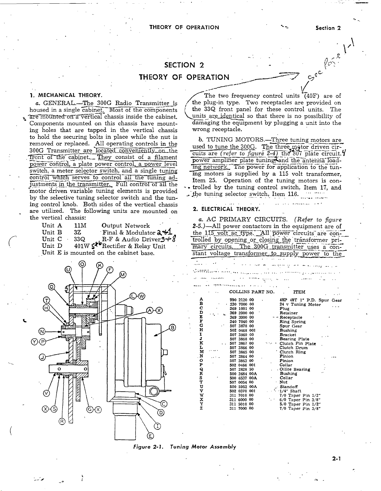
a.
GENERAL
in
housed
a
wilted-
Components
ing holes
the
hold
to
removed
300G
rout of
power
switch,
confrTw
justments
motor driven
by
ing
are utilized. The
or replaced. All operating
Transmitter are - Tocated çönvenlently.-Qn,tlie
the
cofifrol, a plate power
a
meter selector
in the transmitter.
the selective tuning selector switch
control
THEORY.
-The
single
300G
cabinet ---M -c st
olï`rticál' chassis inside
mounted
that are
securing
ábinet_
re serves` too contról`a e uning
variable
knob. Both
following
this chassis have
on
tapped in the
bolts in place while the
They consist of
switch,
tuning
sides
the vertical chassis:
A
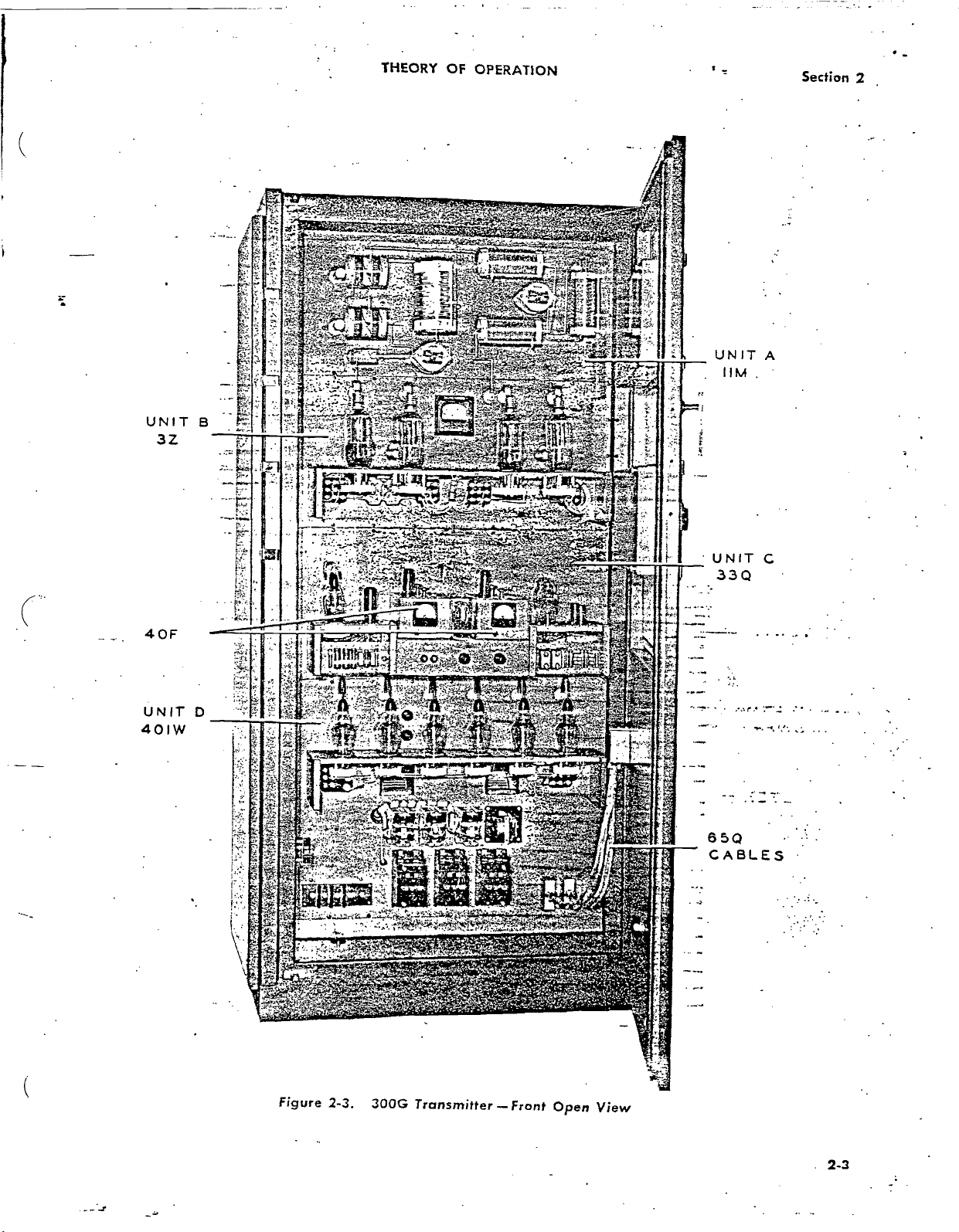
Unit
11M
Output Network
Unit B 3Z Final
C
Unit
Unit
Unit
33Q R -F &
D
401W
E is mounted
/A;
Rectifier
the cabinet
on
THEORY
Radio
Transmitter
th
of
components
the cabinet.
vertical
controls
a filament
control
a power
and a single
Full
control ö
elements
is
and the tun-
of
the vertical
units
are
mounted
& Modulator
Audio Driverj-H
Relay
&
base.
OF OPERATION
is
mount-
chassis
nut is
the
in
level
tunnn
ad-
a the
provided
chassis
on
a°b i
g
Unit
. _---"- ° -./
The
two frequency
plug
! the
the 33Q
units
-in
type.
front
panel for these control
aiejdeptical
damaging the equipment
wrong
used to tune the
cuits are (refer
power
Iñg
mg motors
Item 25.
. trolled by
the
2.
2 -5.)
the 11:b-_-
receptacle.
b. TUNING
MOTORS.
300G. The three tor
to figura
amplifier p ate
netvoc.
The power
is
supplied by a
Operation of the tuning motors
the tuning control switch,
tuning
ELECTRICAL
a.
AC PRIMARY CIRCUITS. (Refer
-All
selector switch, Item
THEORY.
power
ol
contactors
c
£ÿpe..
trolled by opening_or
marÿcircuìts. T
stant voltage transformer to supply
control units (40F)
Two
receptacles
so
that there is no
by plugging a
-Three
2 -4
tunin
for
äpplication
115
in the
A11 power
closirig
.e300G
transmitter
t Or plate
nd
the
cvc
are
provided on
units. The
possibility
unit into
tuning
motors are
driven rir-'
thë_äntéïlriä
tö thé tun -
volt
transformer.
Item
116.
equipment
circuits
transformer
uses ä con-
power
of
are
of
the
circuit.fJ
Ioád-
is con-
and
17,
to figure
are of
are còri
pri-
-toot
the
Figure
2 -1. Tuning
COLLINS
A
B
C
D
E
F
G
a
I
J
K
L
M
.N
o
P
@
R
S
T
U
V
G1 311 7010
X 311 6000
Y 311 5010
z 311 7000
Motor Assembly
990
230 7000 00
369 1001
369
369 3000
340 7040 00
507 3878 00
502 0468 001
507
507 3868
507 3867
507 3866
507 3865
507
507 3863
502
507
500
500 6537
507 0054
500
502
PART NO.
2120 00
00
2000 00
00
3869 GO
00
00
00
00
00
3864
00
001
0466
2828 50 . .
OOA
2684
OOA Collar
00
5952 OOA
0370 001
00
00
00
00
- -
.
ITEM
98P 48T
24 y Tuning
Plug
Retainer
Receptacle
Ring Spring
Spur Gear
Bushing
Bracket
Bearing
Pin
Clutch
Drum
Clutch
' Clutch
,:
Ring
Pinion
Pinion
Collar
Bearing
Oilite
Bushing
Nut
Standoff
1/4" Shaft
7/0 Taper Pin
6/0 Taper Pin
5/0 Taper Pin
Taper
7/0
1"
P.D. Spur
Motor
Plate
Plate
Pin 3/8"
Gear
1/2"
1/2"
2 -1
www.americanradiohistory.com
Section 2
THEORY
OF OPERATION
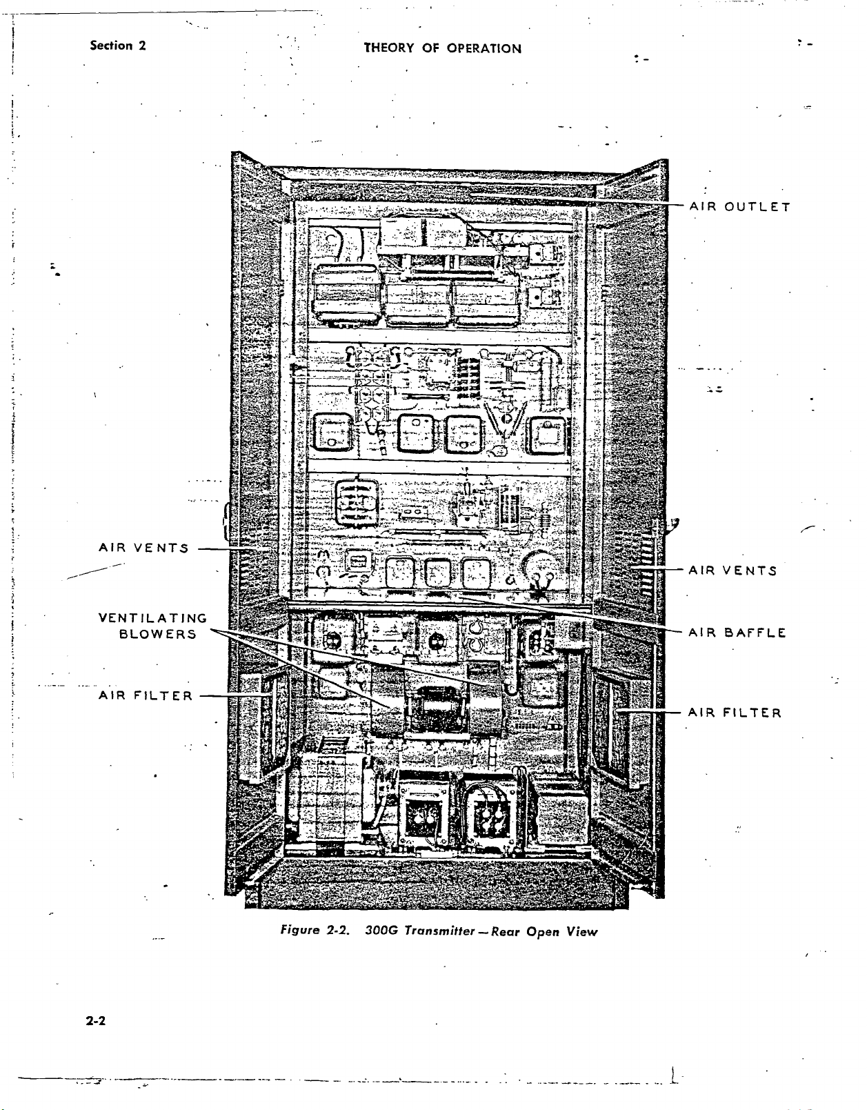
AIR
OUTLET
AIR
VENTS
VENTILATING
BLOWERS
AIR FILTER
Figure
2 -2. 300G
Transmitter
--Rear
Open
View
AIR
AIR
AIR
VENTS
BAFFLE
FILTER
2 -2
www.americanradiohistory.com
THEORY
OF
OPERATION
Section
2
Figure
2-3.
300G
Transmitter
www.americanradiohistory.com
Front
Open
View
2-3
Section
2
O
O
o
O
o .
o
o
O
O
o
o
THEORY OF
o
O
MOD.
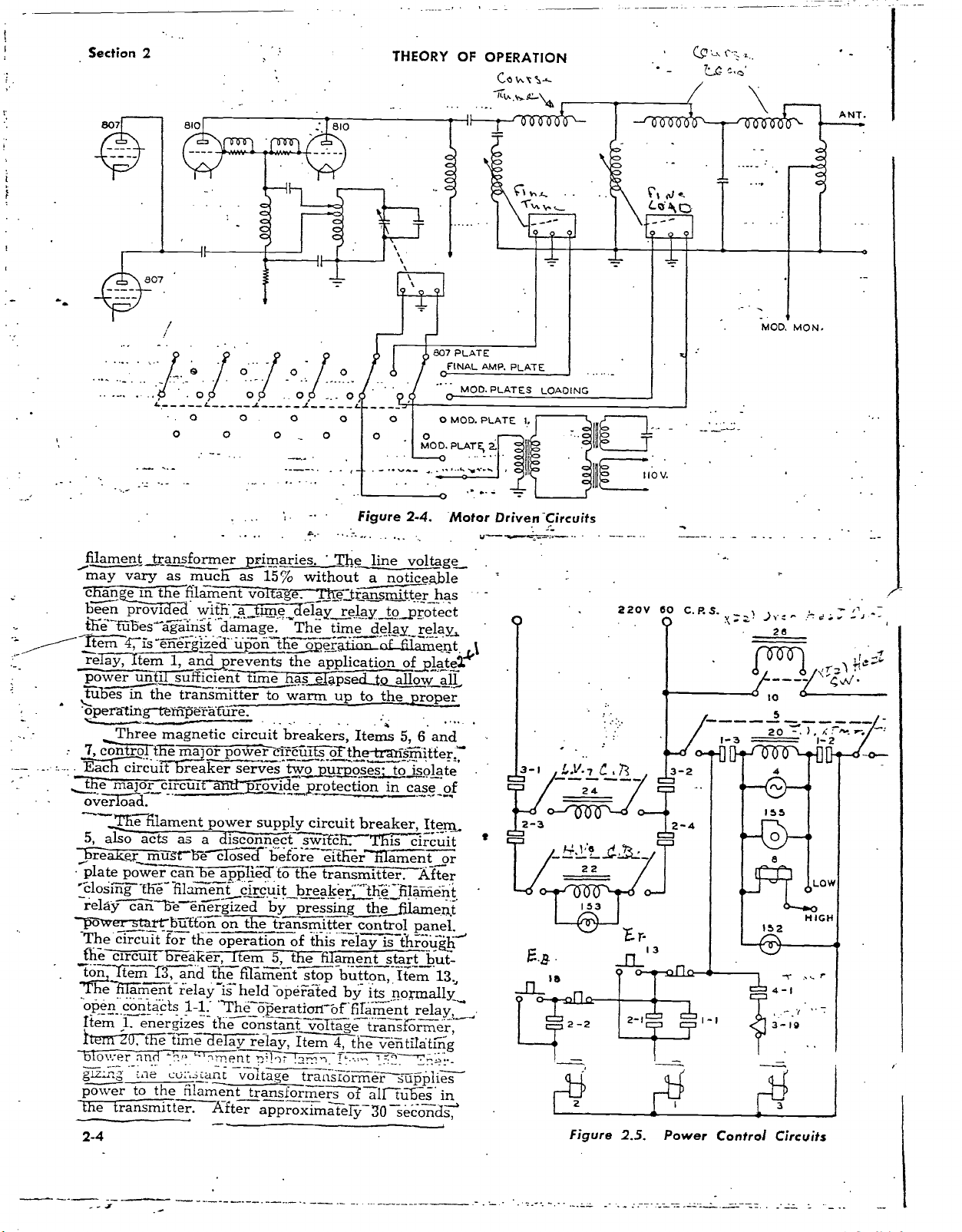
Figure 2 -4.
OPERATION
807 PLATE
OFINAL
AMP.
PLATE
MOD. PLATES
O
MOD. PLATE
PLATE,
2.
O
Motor Driven-Circuits
LOADING
L
IIO V.
MOD.
MON.
filament
may
'chan
béen prove
the
l tÏem
re
powr
tub-5-11.77-the
open
t
7,
- -- - -. -..
tac
the
lié
5,
re
plate
çlosmg
reláÿ
-_ ó
The
£hë circuit
töñ.Ttem
'l'heilámént
open
Item 1,
Ìterñ"20
blouser
g1. :n
power to the
the
2 -4
transformermáries.
vary
as
e in the filament
ed
1tübes ágáirist
'iseñër
aT -Item
-ting- IT.15 "rat
Three
con ro
-
major
also acts
powerr
ver-start~bütto
circuit
contacts
a
fransmitter.
1, and prevents
unt'iI
súfficient
transmitter
magnetic circuit
t
íh major power`
circuit
e
reaker serves
circus
filament
as
mugt-'bè
cá be
-th
-6 filàmeñt
cane
énérgized
for
br- e
f3,
and
irelayis
energizes
-t
íe time
-aker,
1 -l: `Thé'óperatiari-
filament
much
as
vo á
with á time_
-damage.
izéd
üpóii
£-ime
-üre.
aì"ï3ir" ró de
power
a
supply
disconnect
cf
applied-to
circuit
on the
the
operation
i
m 5, tF
the
firameñt
held
the
constant
cTelÿ
relay,
`'`,ment
voltage
transformer-S--o7
After
approximately
.
15%
without
e. e7tran
delay
The
allé
ópérâìi
the
application
has
elapsed-to
to
warm
breakers,
Tcizcüits
two
purposes.
protection
circuit
scarf h
before
éit í1
t&ie
transmitter
breaker
by
pressing
transmitter
of this
ë fiIa
stop-button,
opéiated
voltage
Item
tranSIOrmeT
The
line
voltage
noticeable
a
mitterhas
relay
to_protect
time
delay_
relay,
oL
lament
of_platel
allow ai
up
to the
Items
oTthe-trahsmìtter,7
breaker,
-This
erñlament
control
relay
ments_tartb_ut-
by
bf-firäment
4,
the
T.
á1f
proper
5, 6 and
to
isolate
in
case
of
Item
circuit
or
.
After
hëFfiIan
the_fxlament
its normally__
trañsfr'mér,
vèñtilátirig
,-
30 seconds
panel.
isis
thröügfiJ
Item
relay,
r-rä_-
súpplies
ilb-es in
ent
13,
60
220V
t
a-I
!..v.7
C,ß
24
C.P.S.v+
. --
I-3
>r't
26
lo
5
2 0
-
" - d:
)
R
.
7-ti
1-2
_
r,
t
22
Figure
2.5.
Power
Control
Circuits
www.americanradiohistory.com
THEORY OF OPERATION
Section
2
relay will close the
delay
time
the
Toz the operation
when energ>zëi
voltage cïrcúî
low
However,
ofthë Iów voltage plate
wiTI còìñpiete
before the low voltage
energize i will be
`VOLTAGSÜUPPLY
ore
high
voltage
can be applied to
'grid power amplifier
8F6
OSCILLATOR
'OF
MODULATOR MODULATOR
20
BARG
AUDIO
86e-
866
23
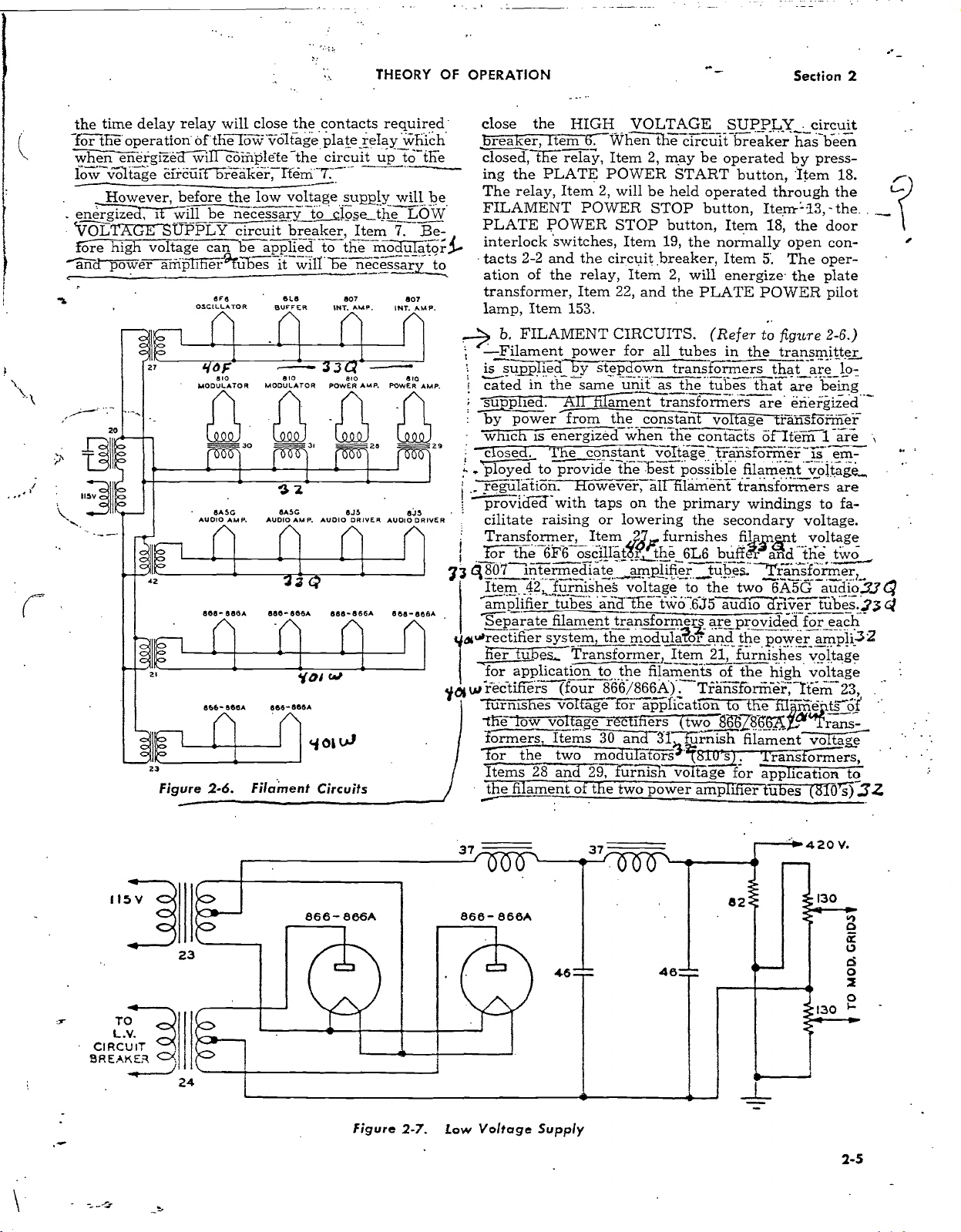
Figure 2 -6. Filament Circuits
contacts
-the
circuit
réäkëi-
Itém...r V '
supply will be
necessary t-o-ç1ose the
circuit breaker, Item
the modulatory
uses it will
810
BL6
SUFFFFER
BIO
necessary
Te-
807
AMP.
{NT.
33Q
810
POWER
z
AMP.
BARG
AUDIO
/\
AMP. AUDIO
6R OJO
DRIVER AUDIO
n
áß
atm.,
866-866A 866-866A
^
Yai w
-868A
866-666A
yot
required'
relay
`Which
up
to -tEe
7.
INT.
AMP. POWER
866-866A
/
LOW
Be-
to
807
.AAMP.
810
AMP.
IIc
DRIVER
HIGH VOLTAGE
close
breaker,
closed,
ing the
The relay,
FILAMENT
PLATE
t
interlock
- tacts
ation
transformer,
lamp,
..-> b. FILAMENT
-Filament power
is supTierI'ÿ
cáted
by power
- *Inch
R
c
. ployed to provide the best possible
r e -Iätion. However,
providë3
cilitate
the
item
6: When t e circuit
the relay, Item 2,
PLATE POWER
Item 2, will
POWER
POWER
STOP button,
switches, Item 19,
2 -2 and the circuit.
of the relay,
Item 22, and the
Item 153.
CIRCUITS.
for
stepdown
in
the same
A i ament
apliE
.
from
hi
is energized-When-tire
ose e constant
with
raising
the
taps
or
unit
lowering
be held
STOP button,
Item 2,
all tubes in
as the tubes
constant
vóltág`e`rráñsf-
alf- filàmëñt
on the primary
Transformer, Item furnishes
the 6F$ oscillät
ro-i7-the
intermediate
8807
et
33
Item_ 42, fúrñishes voltage
tithe
amplifier.
mplifier tubes andië twö'6J5
Separate
filament transformer
a irectifier system, the modulator
fier túbes,_ Transformer, Item
for application to the filaments
rectifiers
w
la
furnishes voi á
low voltage rectifiers
-fhb
formers
or the
Items
fi ament o t e two
the
(four 866
Items
two
28
an 29,1úrnis voltage
/866A).µTräñsförmèr,
e for
application
3Ó .a-3Ì
mo irarers
power
UPPLY
S
breaker
may be
START button,
operated
operated through
Item
the normally
breaker,
Item 5.
will
energize the plate
PLATE
(Refer
trans
o
transformers
voltage
contácts
filamentvoltage
transformers
the
secondary
fil
6L6
buff_
tübeS.
the
to
(two
ürñish
two
au io river tübe_s.
are
provided
and
the power
21,
furnishes
the
of
to the
86Z$56`A
filament
g=7"-
for
amp
ih
er
_circuit
been
has
by press-
'Item 18.
Item'- 23, -the..
18, the door
open con-
The oper-
POWER pilot
to
figure 2 -6.)
the
transmitter
that are lo-
that
are
being
are erieigized
tràïzsförm
öiIïëm
ormër-.-1-i-...&.-
windings
1 We
to fa-
voltage.
voltage
t
the ttó
and
T`rä_nsfö_rmerr
6Á5G
audio3.3
for _each
ampli-32
voltage
voltage
high
-item
filme
.tsof
d Trans-
voltage
fis
Amers,
application to
tubes
(810
the
er
m-
are
23,
s)
?3
' .
32
Q
Ct
115
TO
L.V.
CIRCUIT
BREAKER
24
Figure 2 -7.
37
868A
888-
Voltage Supply
Low
46=
37
48;
82
420 V.
130
130
h
O
u
d
o
2
O
2-5
Section
2
THEORY
OF
OPERATION
TO
H.V.
CIRCUIT
BREAKER
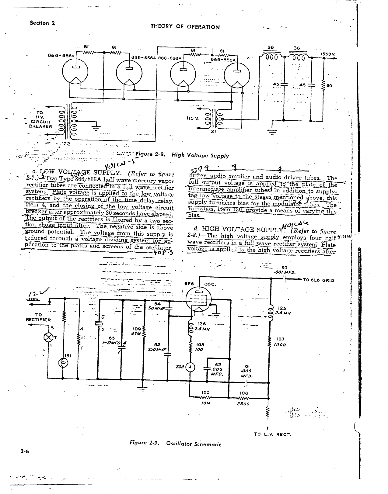
c.
IOW
2,-7.)-2-Two
rectifier
system.
rectifiers
Ttém
Trêär
he
out
tion
choke
_ground
reduced
plication
866
- 866A
.'22
VOIÇE
Type
tubes
are
-
te
vge
by
the
he
after
approximately
ut
oft
potential.
through
o ih-
Frafës
81
SUPPLY.
B6.6/866A
có
necfczin
öIta
is
operation,_
c!osingof
e
rectifiers
fie_
The
voltage
a vol
age
and
81
401
half
applied
of,
the
the
30
seconds
is
filtered
negative
divíC
screens
_-- Figure
(Refer
wave
a fúÌ1
to
the
time delay.,,relay,
low
from
ìñg:
of
to
mercury
wáve_rectifier
löw
voltage
have
elapsed.
by
a two
.side
is
this
supply
tem
the
oscilla
866-856A
2 -8.
figure
vapor
_Xöltage
circuit
sec-
above
is
or
_áp_
pr
High
115
g
Voltage
4
G7
buffer
of fi
output
me
ing-
low
supply
ì
eostats,
d.
HIGH
2 -8.)
-The
wave
rectifiers
ye
866
-866A
1010
21
Supply
1-
audio
amplier
voltageis
amplifier
v-oltáge
furnishes
ëm7
VOLTAGE
high
is
in
applied to
to...the
bias
voltage
a full
the
36
and
audio
appl'ied
tubes
stages.
for
the
a
SUPPLY:
supply
wave
high
36
..
.
_"
45
driver
to
ffie
In
addition
_mention
modulagor
means
z
o'
(cf
(Refer
_employs
rectifier
voltage
system:
rectifiers
45
-`°.-.
tubes.
plate
to
bove
Jibes.
varying
to
four
1550
V.
80
The
of te
s pply-
this
The.: The
h s
figure
half
Plate
after
_:
w
of
Y
TO
RECTIFIER
2-6
151
Figure
2 -9,
6F6
Oscillator
OSC,
10M
Sihematic
_
2500
-
TO
L.V. RECT.
60
.001 MFO.
{TO
6L6
GRID
www.americanradiohistory.com
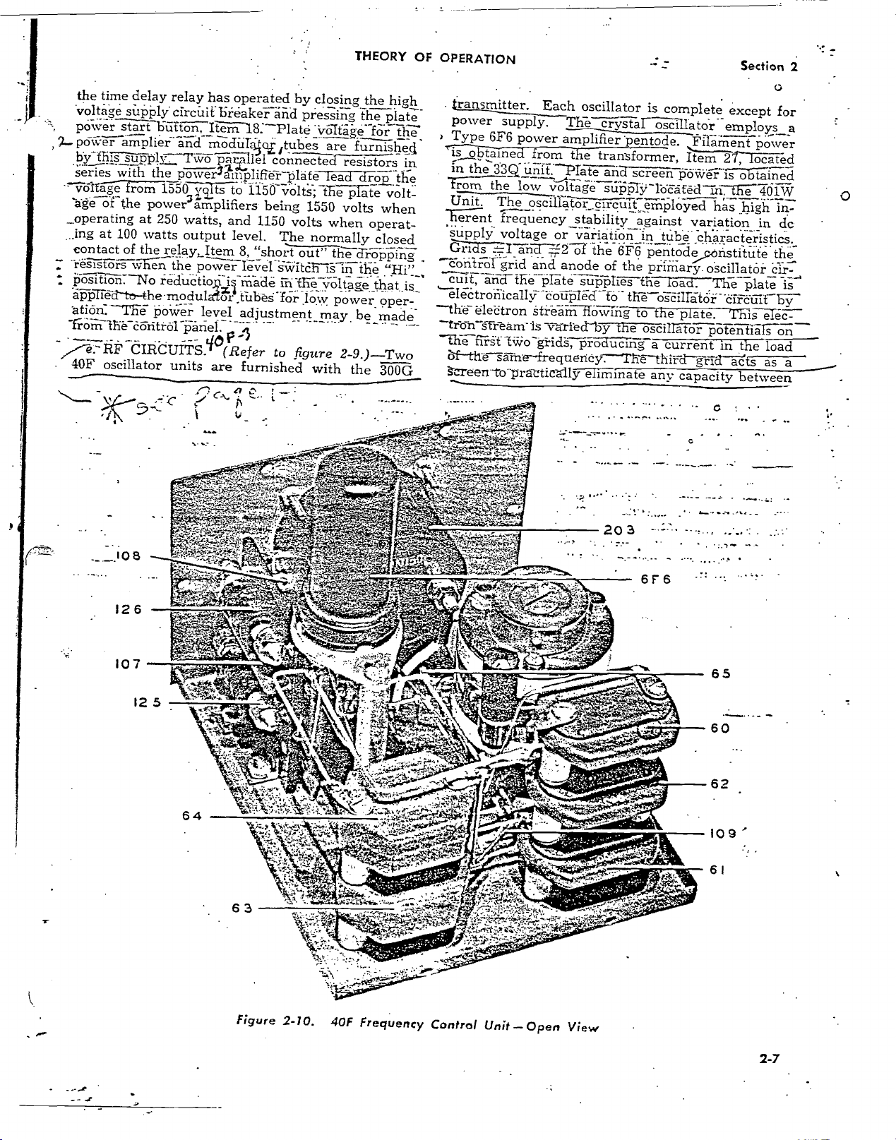
the
time
delay
relay
has
voltage
pcnver
2._
px-r-ampliei
sùly
start
ciercilifbreakei-a-n-d
161-iitIter-ri18.-Platé
and
hy-flipply:::Two-P-a-Eillel
eries
with
the
P-577eillitliffe-i--plate
-'776/ta7,4Trorri1550
-age
orthe
_operating
ing
at 100 watts
contact
"re-graör-sn
P5STIT6Tir-No
4-)p-ribli-tr)-the-modulairiiihèS-fo-r.-.loW
atiön.
power3amplifiers
at
250
watts,
output
of
the relay,Item
the
rerclUCtio4"-ii-fri-ade
'l'he
power
operated
modiili4oL
yil.ts
to
and
level.
8,
pouvez
level
tubes
connected
1150io-lfsTE-6-51-a-e
being
1150
The
"short
switch-is
ih
adjustment_may
-
units
MP-1
(Refer
are
furnished
to
.
CIRCUITS.
40F
oscillator
by
closing
pressing
Viilfa-e.
are
resistors
lead
1550
volts
volts
when
normally
out"
th-e-d-r-o-P-p-rn`g
in
ffieoItage
power,
figure
2-9.)---Two
with
.-.
THEORY
the
high
..
the
plate-
for
the
furnished
dro_pthe
volt-
when
operat-
closed
the
!Hi
that
operT_
be
made
-
the
300G
OF
OPERATION
ransmitter.
power
)
Type
6F6
in
is obtair
in
the
from
the
Unit.
Te-Tent
-
supplY.
67:127
"1E7::
-Conlirceirld
is
CUit,afldthepItesuplies
-the
électron
--tr-o-n-gr-eani-is
--die-fifSt-tiio-sgrid,
ilf-tilè-§à-trie-frequericy.
k...reen.--trrpraztically
Each
oscillator
supply.
power
Th-e-Fry-tas
arnTraerl7)eil.tT.e7Pil-a-Ment-p-Oi.ver
transformer,
3.32.
unit.-PIate
low
voltage
The
oscillat:érnp-loyed
frequency
voltage
I
or
d
and
stream
Tfa'rled-b-y-The
ana-gEFeëh-P-5\7-VeFfs-6-51--i.ined
stability
.
variation
2
of
the
6f6
anode
e
supplies
of
the
Hol,ving-f7the
producing
Théthit-d-g-rTd'
eliminate
Section
is
complete
I-osc-illato-r--employs
against
.
in
tube..characteristics._
except
Item
277-1-6Fared
in,the-4161W
variation
_
in
pentodeñstjtute
road.
plate.
current
capacity
osciflatàrcir-
Tiie---Plat-é-
TElsle-c---
potentiars-on
in
the
acts
between
the
oscillator
a
any
o
for
dc
.tfle
is
load
as
2
a
a
Figure
2-10.
40F
Frequency
www.americanradiohistory.com
Control
Unit
-Open
View
2-7
::,
t-.
.
zeètion
2
-THEORY
OF
OPERATION
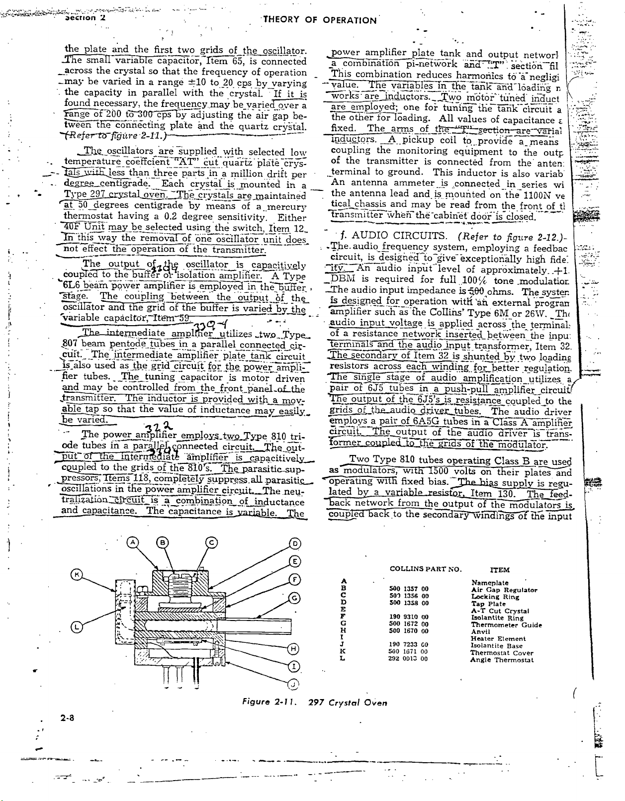
the plate
She small
_across
_may
. the
found
ra
óf 200 tó 30
en
étt
--(-Refer'tb-
Tl3e__oscillators
temperature
_
aTs
-. degree_centiggrade.
Type
at aÓ
thermostat
_40F
this
not
couple
`6L6 bea
stage.
oscillätor
'variable
807 beam
cuït._
is_also
fier tubes.
and may
_transmitter.
able tap
and the
variable
the
crystal
be
varied
capacity
necessary,
the
in
in parallel
connecting plate
fc'gure
coëffcient"AT"
i
less than_t_hree
297 crystal
_degrees centigrade
having
IJñit-m_ay
way
effect
The
to
be selected
the remo
the
operation
output
the buff
pöiv'er amplifier
The coupling
and
the
capacitor, -Ite
Thy
te_-
mediate
pentode
The
iiïtermediate
used as
the.grid
The
controlled
be
'fhé
so
that the value
be varied.
power am p ifier
ode tubes
ut ö
cavilled to
pressors,l%ms
' " osclIla`tions
riTi a.tión;çïrcúltis
1ìï a par
einter tat
the grids_of_
118,
"in tl-ie pöwër
capacitance.
first two
capacitor,
so that
range
a
grids of_th_
rtem
the
frequency
±10
to
with
the
20 cps
crystal.
the frequency_may.be
cQps ley
are supplied
óveïtThe
a
o
r
grid
tubes in
tuning
ductor
The
Jggb
r '
compl
The
adjusting
and
the
with
_cút quartz.
parts
,in
a
Each crystal:
_is
crystals
by
means
0.2 degree
using
r
of
of the
sensitivity.
'the
öiis
ooscillätor
transmitter.
oscillator
isolation
o
is
"between
tfieeli
of
n-59.
ampler
amplifier
circuit
amplifier.
em_pl
-o ed
the
ffer
utilizes
a parallel
plate
for
the power"ampli_
capacitor
from the
of inductance
emplöy_s
nnected
..:_
amplifier
the 810
amplifier
a
combination
capacitance
front._pane_of_tIie
is provided
two
circuit.
s.
The_parasitic-sup-
élp
súppress_all
circuit.,
is
is
e
oscillator.
is
65,
connected
of
operation
by
varying
If
varied
over
the
air
gap
quartz
million
mounted
crÿsfal.
selected
plate
drift
crys-
in
aremaintained
of
a __mercury
Either
switch,
is
output
is
Item_
unit
capacityy
A
iñ
the`6úffer
b
f
varie-ci-by
_tw.o_
does_
Type
Type_
connected
tank_
circuit
motor
Type
is
driven
with
a
mov-
may
easily.
.810tri-
_gut -
he
capacitively__
.parasitic_
-.
The.neu-
of inductance
arable
Theme
it
be-
low
per
12,.
ely
the_
the
cii-
is
a
a
_
power
as ólñblñatïón
_
This
combination
-' va ue.
works-
are
employed;
the
other
fixed.
induçtó
coupling
the
of
terminal
An
antenna
the
antenna
tical chassis
Tránsmittér
f. AUDIO
, _The.
,
...
audio
circuit, is
ifv`
Ari
_DBM
..She
audio
is
designed
amplifier
.audio
of
resistance
a
Tëmlñals
The secondary
resistors
The
sij stage
pair
of 6J5 tubes
'The output
grids of
e mploys
Circuit.
rormer
Two
as modu
operating
lated
b
ack
network
coupled
amplifier
plate
pi- network
reduces
e
variables
areindugtors.
one
for loading.
The
arms
óf _th
s _A__pickup
the
monitoring
transmitter
to
ground.
ammeter
lead
and is
and
may be
when
the
CIRCUITS.
frequency
designed-to
audio input
is required
input
for
such astÌie
input
voltage
ánß& the
across
of thé
the_audio
a pair
The,
coupled
Type
a
ors, w1
wl
va
a
6ackto
for
impedance
operation
network
á_udio
of Item
eác
of audio
in á mush
6J5's
drive
of
6A5G
output
tó tt ejrl
810
tubes
fixed
'able_resistor,Item
from
the
tank
and
'andr"_T"
harmonics
in
the
tank
_ j
wo
tuning
All
values
coil
tó
Motor"
thé
_
section-
_provid_e
for
equipment
is
connected
This
inductor
:is
.connected
,mounted
read
from
"cabinet
door
(Refer
system,
give-
level
full
ColIiils'
is
_applied
employing
exceptionally
of
approximately.
100%
is-480
with
'áì1
Type
across
inserted
_input
32 is
transformer,
shunt
iñding.for
amplification_
-pull
is
,resistance
tubes.
tubes
in
s of
volts
á
the
on
w í ñ
the
of
audio
operating
00
bias e bias__
the
output
seconda
output
networl
sectiöli^
tò
-ä negligi
ii-d
loading
tuned"
tiik
circuit
of
capacitance
are-várial
a_
to
from
on the
ohms.
the outil
the
is
also
in
series
1100N
the
front
is
closed.
to figure
a feedbac
tone
modulation
The_syster
external
6M
or 26W.
the
between
ed
by
two
better
regulation.
amplifier
coupled
The
audio driver
CTäss
A amplifiër
driver
mòaüla
Class
B
t
eir plates
supply
130.
th
ome dulators is
a i n g
s of tj
fil
r
induct
a
means
anten:
variab
vii
ve
of
ti
¡-
2 -12.)-
high fide:
progran
Th<
terminale
the
inpu:
Item
32.
loading
utilizes
circuit
to the
is trans -
or.
are used
regu-
is
The fe_ed-
input
e
I
a
2 -8
0
O
0
Figure
2 -1
a
0
0
o
o
1.
297
A
B
C
D
E
F
G
H
J
K
L
Crystal
Oven
COLLINS
500
1357 00
501
1356
500
1358
190
9310
500
1672
500
1670
190
7233
500
1671 00
292
0013
PART
00
00
00
00
00
GO
00
NO.
ITEM
Nameplate
Air Gap
Locking
Tap Plate
A -T Cut
Isolantite
Thermometer
Anvil
Heater
Isolantite
Thermostat
Angle
Regulator
Ring
Crystal
Ring
Element
Base
Thermostat
'
Guide
Cover
32
83
3900n 250M
2000MMF
113
/OOMMF
AUDIO
6145
AMP
THEORY OF
DRIVER
6A5G
OPERATION
.POWER
BIO
.
AMP.
2000MMF,
+
LV. LV.
RECTIFIER
LV.
RECTIFIER
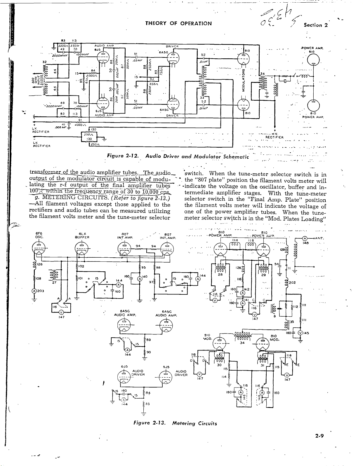
transformer
output
lating
100
-All
rectifiers
of the moduläto-
the
-7:
vliT iln
filament
and
the filament
6F6
05C.
49
41
4000n.
250n.
the
of
audio amplifier
r -f output
iê frequency
CIRCUITS.
voltages
audio
tubes
volts
meter
61_6
BUFFER
2000n
Am°
U010
130 ?
ti
250n
Figure
iicúit
of
the
range
except
can
and
the
956n
ó
2 -12.
tubes.
is capable
Audio
The
of
final amplifier
of
30
to 10,000
er
Re
( f figure
be
to 9'
those
applied
measured
tune -meter
807
utilizing
selector
90
6Á5G
DRIVE
Driver
_audio__
modu-
t
s
cps.
2 -13.)
to the
807
R
and
Modulator
'switch. When the
"807
the
-indicate the
termediate
plate" position
voltage on
amplifier
selector switch
the filament
one of the power
volts meter
meter selector switch
810
..POWER
Schernatic
tune
stages.
in
the "Final
amplifier
is
AMP. .. .
IIr7
-meter
the
filament
the
oscillator,
will
tubes.
in
the "Mod.
era
POWER
118
o-o
RECTIFIER
.
selector
With
Amp.
indicate
switch
volts
meter will
buffer and
the
tune
Plate"
the
voltage
When
Plates
the
Loading"
BIO
POWER AMP.
is
in-
-meter
position
tune
ANT.
148
in
of
-
144
27
30
114
115
160
160
ODQ9Q
34
147
160
\oE
147
118
b
-oE
2 -9
116
---.
147
BASG
AUDIO
6J5
AMP.
Figure
6Á5G
AUDIO AMP.
6J5
2 -13.
AUDIO
DRIVER
Metering
910
MOD.
147
Circuits
s
www.americanradiohistory.com
Section 2
THEORY
OF
OPERATION
position
age
"Mod.
the
former,
the filament
on the remaining
Plate
1"
voltage
across
Item 31. To
modulator tube
in the
of the oscillator
mounted
"Mod.
in
Plate
the 40F
the 6L6 buffer
switch.
cathode
tubes
on meter
circuit
the
and
can
"807
6J5
Item
can be
audio
15, in
current of
be read
Item
grid"
volts meter
position
the
check
place
2"
can
be read
Unit.
can
be read
the
the
at all
140.
The
read
with
position.
driver
will
power
amplifier
the filament
modulator
the
voltage
the
tune-meter
position.
The
by the meter,
The
cathode
with
6L6 cathode
807 intermediate
times,
without
intermediate
the
test
The
6A5G
tubes
cathode
read the
tube.
voltmeter
filament
on
selector
cathode
current
the
test
position.
switching,
amplifier
meter
switch
audio
current
volt-
In
the
reads
trans-
the
other
switch
current
Item
203,
of
meter
The
amplifier
grid
in
amplifier
is read
with
cathode"
the
power
meter,
amplifier
141.
modulator
000
ohm resistors
age
meter.
; with
_Plate
current
antenna
meters
oscillator
are
mounted
the
cabinet.
the
test
positions
Item
is
The
plate
is read
the
tune-meter
1"
and
is
read
current
with
cathode
meter
respectively.
amplifier
142.
The
metered
voltage
with
are in
The
modulator
"Mod,
with meter,
is
the
exception
current
on
the
switch
is
metered
cathode
at all times
of the power
meter, Item
series
selector
Plate 2"
read
with meter,
and
meter
panel on
in
the
"6J5
The
grid
at all
current
with
of the
meter,
amplifier
145.
with
this plate
cathode
positions.__The
Item 148.
switch
current
in "Mod.
The remote
Item
of those
the
measuring
r-f
line
the front door
and
current
times
power
Two
is
r-f
143.
current
6A5G
of
with
Item
and
100,-
volt-
read
line
All
the
of
2-10
www.americanradiohistory.com
INSTALLATION
AND INITIAL
ADJUSTMENTS
Section
3
I- INSTALLATION.
PRELIMINARY.
a.
UNCRATING. - Caution should be
(1)
uncrating to avoid
:ven
A nail
instead
inspected
make
spect each
all controls
operation as far as
application of power.
be filed promptly
puller
of
should be used
a hammer or
carefully. Inspect
sure that
all cable
unit for loose
such
as switches,
with the transportation
INSTALLATION
damage to the equipment.
remove the
to
All
bar.
units should be
cables and
connections are tight. In-
and
dials,
etc.,
determined
for
damage should
bolts.
cán
be
All
screws
claims
SECTION
AND INITIAL
used
nails
wiring and
Check
for proper
without the
company.
3 '
b.
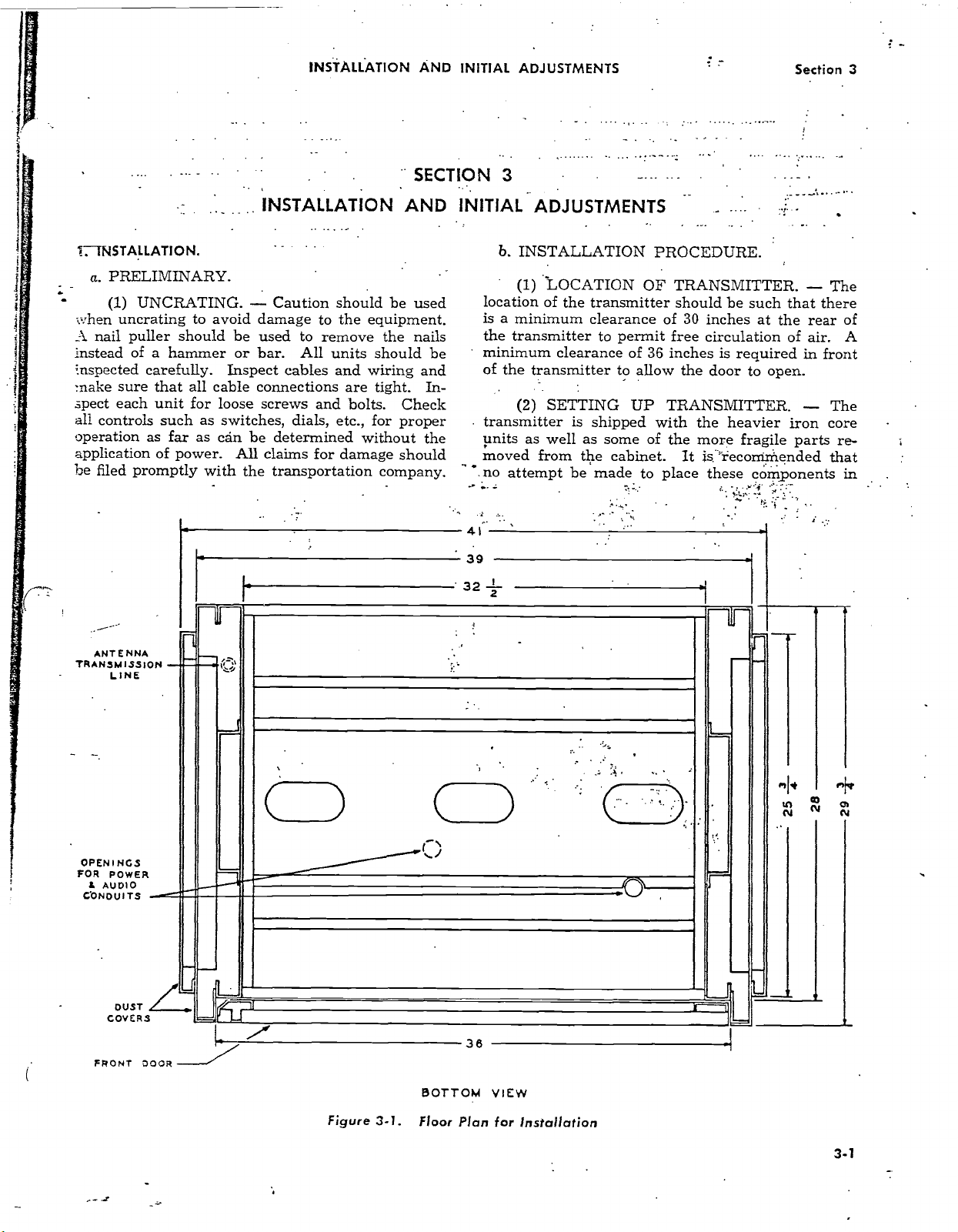
INSTALLATION
(1) LOCATION
location
is
a
minimum
the
transmitter
minimum
the
of
(2) SETTING
transmitter
units
as well
moved from
no
attempt be
41
39
32
z
ADJUSTMENTS
OF TRANSMITTER.
of the
transmitter should
clearance
permit
to
clearance
transmitter
of
36
to
allow the
UP TRANSMITTER.
is shipped
as some of
the
cabinet. It
made
to
PROCEDURE.
be
such that there
30
of
inches at
free circulation
inches is
required in front
door to
the
with
the more
place
heavier
fragile
'reconiriiended
is.
these
components in
- The
the rear of
air. A
of
open.
- The
iron
parts
core
re-
that
ANTENNA
TRANSMISSION
LINE
OPENINGS
FOR
POWER
1. AUDIO
CONDUITS
¡
DUST
COVERS
FRONT DOOR
n4
f
1 I
f
36
BOTTOM
VIEW
Figure 3 -1.
www.americanradiohistory.com
Floor
Plan
for Installation
3 -1

Section 3
INSTALLATION
AND
INITIAL
ADJUSTMENTS
3 -2
1-2.
300G Transmitter
www.americanradiohistory.com
-
Pear. ViAi
Too
 Loading...