


l
t
Collins Government
Telecommunications
Group
Revision, 1
3rd
523-0556933-302831
April
10
August
1969
1977
,F
Rockwell
lnternational
Collins
Rotatable
Collins Government
(\
_j
--:
\_-
:_.
-
4'l
/4Ta
'\
.z t
\- ri
\
\-
&,5^
instruction book
2378,-3
Directional
HF Antenna
Telecommunications
Rockwell I nternationa!
Printed in
!.
,
Dallas,
, :
Texas
United States of America
Group
25207
"
;P,,
E't
t
,s'-'
nn,
,
Ziqarfi:3iqq
3A
f-t,
{t'ltii
>T
2,1
o'r'v,€
1c"'i.:3c7i
tt;
Q
Eefl''
Q
(?
c;u/(
';
W*
i,^,
b
i
\
'..
[ltr-c-
Qttl
\)),'qY'
r,fry
'-
,R\)lgvrl
h\
c
lt
BE
e
-Jct-3
.,{,J.-\r-
))i ::
r-
fl
"14
ls'Y
*,-\.,'.
-.,fX,

tahle of
eontents
Page
Section
1.1
1.2
1. 3
1.4
1.
1.6 Optional
1.7 Items
1. 8
1. I Service
Section 2 lnstallation ... .
2.1
2.2
7 General Descnption
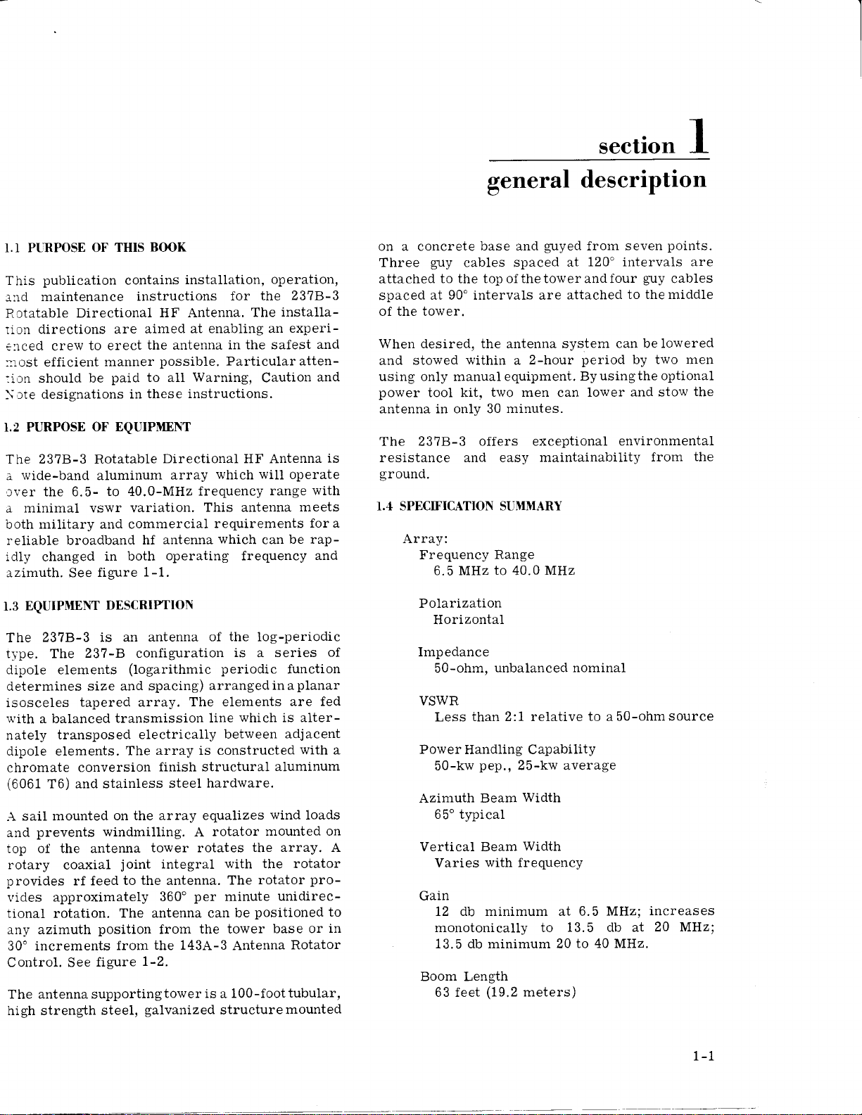
Purpose of This
Purpose
Equipment Description
SpecificationSummary
Equipment Supplied
5
Packing Dimensions and
General
Site Selection. .
Equipment . . .
of
Equipment
Required
Information
2.3 Foundation and
Construction....
2.4
2.5
2.6
2.7
2.8
Assembly
Installation of
Transmission
Antenna
Erection
Stowing of
2.9 143A-3
2.10 Radio
of the Tower
Array Installation
the Tower
of
Antenna
Rotator Control Unit
Frequency Interference
Book .
But Not Furnished
Shipping Data.
.
Assembly Anchor
Guy
Rotator
Line Kit . .
Kit. Control
.
Kit
Installation
Kit
Point
and
1-1
1-1
1-1
1-1
1-1
l-4
l-4
l-4
l-4
l-4
2-l
2-l
2-t
2-l
2-2
Rf
2-14
2-25
2-26
2-30
2-30
2-30
Section
3.1
3.2
3.3
3.4
3.5
Section
Operating Instructions
3
General
Operation
LocaI
Remote
Control
143A-3
Stowing of
Theory
4
Operation From
Antenna Rotator Control Calibration
Antenna
oJ Operation
4.1 General
4.2 Local Rotator
4.2.1
4.2,2
4.3
4.3.
General
Operation
Remote
Control
1 General
4.3.2 Operation
the t43A-3
Controt Circuit
Circuit
Antenna Rotator
(Tower
Base) .
3-1
3-1
3-1
3-1
3-1
3-52l3-6
4-l
4-l
4-l
4-l
4-2
4-2
4-2
4-2

table of
eontents (cont)
Sectionslilaintenance....
5.1
5.2
5.2.1
5.2.2
5.3
5.3.1
5.3.2
5.3.3
5.3.4
5.3.5
5.4
5.4.1
5.4.2
5.4.3
5.4.4
General
Lubrication
Rotator
Erecting
Winch and
Inspection
Antenna Tower
and Guy Cables
Rotator
Antenna
The 143A-3
Obstruction
Antenna Tower
Array
Antenna Rotator
Light
Coating/Painting
SurfacePreparation....
Pre-Primer Coat
Primer Coat
Top Coat
(CPN
(CPN
005-1494-xxx)
Pulley Block
Control
.
Control
(CPN
005-1494-010)
. 5-3
'
005-1494-070)
..
Page
5-1
5-1
5-1
5-1
5-1
5-1
5-1
5-2
5-2
5-3
5-3
5-3
5-5
5-5
5-6
list of
Figure
1-1
l-2
2-l
2-2
2-3
2-4 Rotator
2-5 Rotator
2-6
2-7 Instal}ation of
2-8 Installation of
2-9 Installation of
2-10 Boom
2-10A Antenna Array Center Boom
2-ll Boom Assembly,
2-12 Boom
2-l2A
2-13
illustrations
2378-3 Rotatable
143A-3
Anchor
Anchor and Foundation
Installation
Antenna Rotator
and
Assembly
Heater Kit Instaltation
Installation of
Assembly,
Latching Assembly,
Assembly, Rear.
Antenna Array,
Balun Components .
Installation of
Directional
Foundation
Erection Kit
of
Rotator
Rotator Control
Obstruction
RF Transmission
Center
Installation
Front
Transmission
..
Antenna Array
Control
Details
Details
Kit . .
.
Antenna
HF
(3000-PSF
(1000-PSF
..
Kit. . .
Lighting Kit .
Kit ..
Line
Section
and
Details
and
Soil)
Soit)
.
.
.....
.. .
Page
1-0
l-2
2-3/2-4
2-7/2-8
2-9/2-10
2-15/2-16
2-17/2-18
2-19/2-20
2-21/2-22
2-23/2-24
2-25
2-27/2-28
2-30A/2-308
2-31/2-32
2-33/2-34
2-34A/2-348
2-35/2-36
ii
Revised 15 JuIy
19?1
list of
illustrations
(cont)
Figure
2-14
2-15
2-16
2-17
2-18
Winch and
Antenna
InstaIled
Antenna
Antenna
Antenna Raising
2-19 Radio
3-1
3-2
4-l
4-2
4-3
4-4
4-5
4-6
4-7
4-8
4-9
5-1
Local Control
143A-3
Indicators
237B-3
6.5-MHz
10-MHz
20-MHz
30-MHz
40-MHz Elevation
Azimuth
Plot of Vertical
143A-3
Photoelectric
Diagram
Block Assembly
Lowered
in
During
During
Frequency
Erection
Erectlon
and
Unit,
Antenna
Directional
Elevation
Elevation
Elevation
Elevation
Plane
Antenna
Rotator
Patterns,
Angle Versus
Rotator
Obstruction
in Use
Position With
With Array
With
Lowering
Interference
Controls
Control,
HF Antenna,
Plane
Plane
Plane
Plane
Plane
Patterns,
Patterns,
Patterns,
Patterns,
Patterns,
237B'-S Antenna
Control,
Light Switch,
Erecting
Hinging
Array
Checklist
Locked
Placard
Kit Installation
and Indicators
Controls and
Design
Frequency
Schematic
Parameters
237B-3
237B-3
237B-3
2378-3
2378-3
Schematic
Mast
Detail
Antenna
Antenna
Antenna
Antenna
Antenna
. . . ..
...
. . . .
. .
. .
Diagram . ..
.. . .
. . . .
. . .
. . .
Page
2-4t
2-42
2-43
2-44
2-45
46
2-
3-2
3-4
4-2
4-3
4-7
4-3
4-4
4-4
4_5
4_5
4-6
/4-8
'.
.
5-4
Table
1-t
l-2
1-3
3-1
3-2
5-1
5-2
5-3
Equipment
Optional
Packing
Loca1
143A-3
Supplied
Equipment
Dimensions
(Tower
Antenna
Indicators
Recommended
Spraying
and
Spraying
Equipment,
Carboline
Equipment,
Base)
Rotator
Tower
1294
Shipping
and
Controls,
Control,
Coatings
Carboline
Coat
ToP
Rustbond
Data
Fuses and
Controls
WP
1037
Primer
6C . . .
list of
Indicators
and
Primer
Wash
...
tahles
Page
r-5/t-6
'
5-7
/5-8
5-7
/5-8
l-4
l-4
3-3
3-3
5-6
1r1

general
descrrptton
1-0
Figure
si-)
ts*
k\
t$
ti
ti
I t;i
1-L. 237B-3 Rotatable Directional HF
Antenna.
seetion
I
BOOK
1.1 PLIRPOSE OF
publication
This
maintenance
a:rd
Rotatable
directions are
rion
elced crew
::.:.ost efficient
:1on should be
designations
\,:te
1.2 PURPOSE OF
THIS
contains
instructions
Directional
aimed
to erect
manner
paid
in
EQUTPMENT
the antenna
to all
these instructions.
The 23?B-3 Rotatable
wide-band
a
:ver the 6.5-
minimal vswr variation.
a
military and commercial
both
reliable broadband
idly
changed
azimuth. See
aluminum
to 40.0-MHz
hf
in both
figure
1-1.
installation,
HF Antenna.
at enabling an
in the safest
possible.
Directional HF Antenna
array
Particularatten-
Warning,
which
frequency
This antenna
requirements
antenna
which
operation,
the 2378-3
for
installa-
The
Caution
will
range
can
experi-
operate
meets
be rap-
operating frequency
and
and
is
with
for a
and
general
on a concrete
Three
attached to the
spaced
of the tower.
When desired, the antenna system can
and
using only manualequipment.
power
antenna in only 30
guy
at 90' intervals are
stowed
tool kit,
The 2378-3 offers exceptional
resistance and easy
ground.
base and
cables spaced
topofthetowerandfour
within
2-hour
a
two men
minutes.
deseription
guyed
maintainability
frotn seven
120" intervals are
at
attached
period
Byusingtheoptional
lower
can
environmental
f.4 SPECIFICATION SUMMARY
Array:
Frequency
6.5 MHz
Range
to
40.0
MHz
points.
guy
cables
to the middle
be lowered
by two men
from
the
the
and stow
EQUIPMENT
1.3
2378-3 is an
The
tl'pe. The
dipole elements
determines size
isosceles
rvith
a balanced
nately
transposed
dipole elements.
chromate
(6061
T6) and stainless
sail mounted
A
prevents
and
top of the antenna
rotary
provides
vides
tional rotation.
any azimuth
30o
Control. See
The antenna supportingtower
high strength
approximately
increments
DESCRII"IION
antenna
237-8 configuration
(logarithmic periodic
and spacing)
tapered array.
transmission
electrically
array is constructed
The
conversion
on the array
windmilling. A
coaxial
rf feed
position
figure
steel,
finish structural
steel
tower rotates
joint
integral
to the antenna.
360'
The antenna can
from
the 143A-3
from
1-2.
galvanized
of the
arrangedinaplanar
log-periodic
is
series
a
The elements
which
line
between
is alter-
aluminum
hardware.
equalizes
rotator
with the rotator
per
minute
the tower
is
a
structure
wind
mounted on
the array. A
rotator
The
unidirec-
positioned
be
base or
Antenna
100-foottubular,
of
function
are fed
adjacent
with
a
loads
pro-
to
in
Rotator
mounted
Polarization
Horizontal
Impedance
50-ohm,
VSWR
Less
PowerHandling
50-kw
Azimuth Beam
unbalanced nominal
than 2:1 relative
Capability
pep.,
25-kw average
Width
65'typical
Vertical Beam
Varies
Gain
Width
with frequency
72 db minimum at 6.5
monotonically to
13.5 db minimum 20
Boom Length
(19.2
63 feet
meters)
to
a50-ohmsource
MHz;
13.5 db at
to 40 MHz.
increases
20 MHz;
1-1

general
descnPtlon
F
:f
9o
JC
FJ
z()o
oqe
-JF
*"*;5
H
ai
-E5u
x
(}
cm
o
Edt
UF
&7
o
o
6
a
a
>U
63
ro
or
z
x
(D
*<)
iitr
v=
<{
t
E
(B
)
x
o
fi
T
E
td
:a
(r,
I!
g0
=
z*.
()o
F
Ir<
()
trt
35
o2
{L-
ldy
tLLL
(\lNN
3=
o=
a-a
)
(J
rr- E
L l"rl
o
oa
J
&, tf)
)a
()
1
z
Lrl
o
z.
o
l,
F
:E
&
6
m
t-2
()
*8
Z
(/)I]J
\2
e2
98
Figure
1-2.
143A-3 Antenna
Rotator Control.
general
descrlptlon
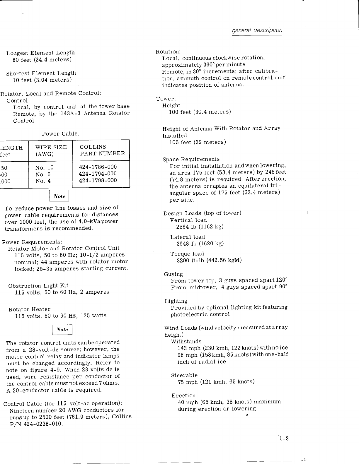
Longest
80 feet
Shortest
10
feet
Rotator,
Local
Control
Local,
Remote,
Control
ENGTH
eet
t50
r00
.000
reduce
To
power
over
cable
1000
transformers
Power
Requirements:
Rotator
115
volts,
nominal;
locked;
Obstruction
115 volts,
Rotator
115 voIts,
Element
(24.4
meters)
Element
(3.04
meters)
and
by control
the
by
Power Cab1e.
WIRE SIZE
(Awc)
10
No.
6
No.
4
No.
power
requirements
the use
feet,
recommended.
is
Motor
and
to 60 Hz;
50
amperes
44
25-35
Lighi
to 60 Hz,
50
Heater
to
50
Length
Length
unit
Control:
at the
Remote
143A-3 Antenna
COLLINS
PART
424-t786-000
424-7794-000
424-1798-000
line
losses
and size
for
of 4,0-kVapower
Rotator
Control
lO'lf2
rotator
with
amperes
Kit
60 Hz,
starting
2 amPeres
125
tower
Rotator
NUMBER
distances
Unit
amperes
motor
current'
watts
of
base
Rotation:
Local,
continuous
approximately
Remote,
azimuth
tion,
indicates
Tower:
Height
100 feet
Height
of Antenna
Installed
105 feet
Space
Requirements
initial
For
an area
(?4,8
the antenna
angular
per
sj.de.
Design
Vertical
2564 rb
Lateral
3648 lb
Torque load
3200 ft-lb
Guying
From
From
Lighting
Provided
photoelectric
clockwise
Per
minute
on
in 30o
360"
increments;
control
position of antenna.
(30.4
meters)
With Rotator
(32
meters)
installation
1?5 feet
meters)
space
Loads
load
(1162
load
(1620
tower
midtower,
by optional
(53.4
required.
is
occupies
1?5 feet
of
(top
of
ke)
kg)
(a42.56
3
top,
tower)
guys
4
kgM)
guys
control
rotation.
after calibra-
remote
andwhen
control
and
meters)
After
equilateral
an
(53.4
spaced
spaced
lighting
kit
Array
lowering,
245feet
by
erection.
tri-
meters)
apart
apart
featuring
unit
120"
90'
rotator
The
a
from
motor
must be
on
note
used,
the control
20-conductor
A
Control
Nineteen
up
runs
control
28-vo1t-dc
control
changed
figure
wire resistance
cable
Cable
number
2500 feet
to
P/N 424-0238-010.
units canbe
source;
relay
accordingly.
4-9.
must
cable
(for
115-volt-ac
20
operated
however,
indicator
and
Refer
28 volts
When
per
conductor
not exceed
7 ohms.
is required'
operation):
AWG conductors
(?61.9
meters),
the
lamps
dc is
Collins
to
of
for
Wind Loads
height)
Withstands
mph
143
mph
98
of radial
inch
Steerable
?5 mph
Erection
mph
40
during
(wind
veloci.ty
(230
kmh,
(158
kmh,
ice
(121
kmh,
(65
kmh, 35
erection
measured
122knots)withnoice
knots)with
85
knots)
65
knots)
one-half
maximum
or lowering
at array
1.)
t-u
-i,

general
descrrptrcn
r.5 EQUIPMENT
The equipment supplied consists
in table
r.6
The optional equipment available consists
1-1.
OPTIONAL
items listed
SUPPLIED
EQUIPMENT
in table 1-2.
the items
of
For operation of the rotator intempera-
tures below +10'F
mended that the rotator
changed
to a
Molub-Alloy or
Imperial Oil and
Wilshlre
The
optional Rotator
8605
t.7
ITEMS
a.
Site
BIvd, Los
alternative
-002.
REQUIRED
for antenna
(-12.2"C)
lighter
Artic
grade,
Gear
Grease
Angeles
would
be
Heater
BLIT
NOT FURNISHED
it is recom-
gear
oil be
such as
Oil.
Contact
Co.,
California.
to install the
Kit,
CPN 515-
Tabte
6505
1-1.
listed
of the
Equipment
b.
Concrete and
and anchor
C.
Coaxial
transmitter
Andrews He1iax recommended)
d.
Control
control
if remote
dc operation)
Coaxial cable flange,
EIA
Power
f .
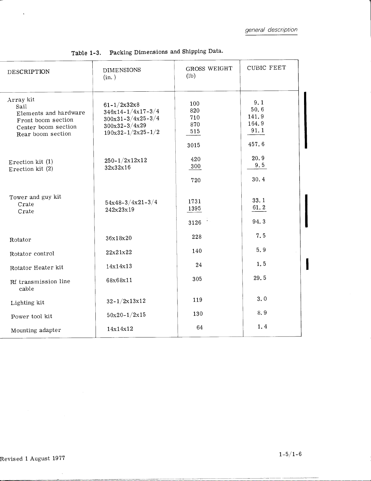
r.B PACKING
Packing
nished in table
r.9
SERYICE INFORMATION
Inquiries
be
directed to: HF Antenna Product Line Pro-
gram
International, Dallas,
2
14-690-5029.
-
t,
+:_.2
a,A
Ert:-
iil-
..:
Supplied.
cable
dimensions and shipping data
concerning the
Manager,
.i,o
.z
tl
'.:
reinforcing
assembly encasement
rf transmission
and
antenna base
cable, 18-conductor,
unit
and antenna
steel for tower base
line cable between
(1-5/8-inch,
between remote
(20-conductor
base
control unit is modified for 28-volt-
1-578-inch
to antenna.
DIMENSIONS
1-3.
Collins
*_:
i
;
',
:
l- u
\Lu-.
AND
SHIPPING DATA
237B-3
Radio
Texas
l/,.l.-'l.r;i-
;
Group, Rockwell
,
Antenna
75207. Phone
standard.
fur-
are
should
COLLINS
758-
758
-
515-8012-001
515-8551-001
515-85?6-001
5
15- 8600-00
COLLINS
51 5-8453-001
515-8601-001
51 5-8524-001
51 5-8605-002
51
5
-8606
PART NUMBER NAME
5346-002
5346- 00 1
PART
-001
1
NUMBER
2378-3 Antenna
Antenna array
Tower,
Rotator
Rotator
Rf transmission
Table 1-2.
NAME
Lighting
Power tool kit
Erection kit
Rotator heater
Rfi kit
kit
guy,
md anchor
kit
control kit
line kit
Optional Equipment.
kit
kit
(to
meet MIL I 26-6)
kit
PARTS BREAIOOWN
KIT
REFER TO FIGURE
2-13
,
2-L0
2- 10A, 2- 11,
,
2-12,2-L2A
2-l
2-6
2-7, 4-9
2-9
KIT PARTS
REFER TO FIGURE
2-8
2-3,
sheet
2-3, sheet 1
OR
2-t9
BREAKDOWN
2
1-4
I
Revised
1 December
1975
general
descrrptton
DESCRIPTION
Array
kit
SaiI
Elements
Front
Center
Rear
Erection
rection
E
Tower
boom
boom section
boom
kit
kit
guY
and
Crate
Crate
and
section
section
(1)
(2)
kit
Table
hardware
1-3.
Packing
DIMENSIONS
(in.)
6l-l/2x32x9
346x14-
300x31-3/4x25-3/
3gg1tl-t
190x32-
250-l/2xl2xl2
32x32x16
54x48-3/
242x23x19
Dimensions
t/ 4xl7
i
4x29
-3/
t/2x25-t/2
4x2l-3/
and Shipping
4
4
4
GROSS
(rb)
100
820
710
870
515
5
301
420
300
720
1
173
5
139
3126
Data'
WEIGHT
CUBIC
1
9.
50.6
9
141.
164.9
91.1
6
457.
20.9
9.5
4
30.
33.1
6t.2
94. 3
FEET
Rotator
Rotator
Rotator
R.f transmission
control
Heater
cable
Lighting
Power
Mounting
kit
tool
adaPter
kit
kit
line
Bx20
36x1
22x21x22
14x14x13
68x68x11
32-l/2xl3xl2
50x20-l/2x15
l4xl4xl2
228
140
24
305
119
130
64
7.5
5.9
1.5
29.5
3.0
8.9
1.4
Revised
1
August
1977
r-5
/t-6

seetion
2
installation
ZT GEMRAL
This section
the 2378-3
selection and
Site
should be
contains
Rotatable
performed
installation. Installation
form of
ings
possible,
procedures
ment. In making the
written, step-by-step
pictures.
and
in
are
are
drawings and emphasis
procedure
the
steps. Refer
identification, and
optional
22
Site
factors; only
will
a.
equipment.
SITE SELECTION
selection
be
covered
for
those
Physi.cally, the antenna requires a clear
area,
meters) for
operations.
pies
175
feet
a space
triangle 1?5
installation instructions for
Directional HF Antenna.
training of installation crews
prior
to starting antenna
instructions are in the
procedures,
procedures,
The
chronological
as nearly as
order. Installation
also listed for optional equip-
installation, refer to the
notes
which
to table 1-1 for kit
table 1-2 for a
the
antenna
directly
in this section.
(53.4
meters)by 245 feet
initiai installation and lowering
When
erected,
in the form
(53.4
feet
depends
relating tothe237B-3
the
antenna occu-
of
an equilateral
meters) on
To facilitate accurate vertical
guy
of
should be 1evel
anchor
tower base and
2-L,
sheet
tion in
plans
tion in
2-2,
It is
1,
3000-psf
and construction
1000psf
desirable to
site in order
Other
are ease
of
compllance
tions
airfield
agency.
in
considerations
of
the
antenna
covering
zoning of
possible,
If
locations
access
on or near anairfieldrequires
with
lateral airfield
where
loops,
within
to
guy
anchor
were designed
soil; however,
soil are
to maintain this firmness.
and
civil
the airfield operating
avoid
wind ducting
ground
the
percent.
t2
plans
for
details for installa-
furnished in figure
well drained
choose
in
a
selecting
routing. Siting
cable
or military regula-
clearance
siting
the antenna
may
dralv-
line
accompany
listing
on
placement
selected
of
many
(74.8
side.
a
Antenna
in figure
installa-
alternate
the site
and
occur.
Wind ducting
and./or
antenna structure. Typically,
multipty the
occurs near
can cause severe
wind
effect
cliffs, canyons,
turbulence
on
an exposed
wind
built up
ducting
areas
or rugged terrain.
b. For
the
best site selection electrically, avoid
obj ects in the immediate vicinity
antenna
flect radiated energy such as large
woods,
The balanced
minimizes
good ground
vertical angle of
conductivity in
for the antenna, its transmission
as sociat ed
ure to
base for lightning
the lightning stroke seeking
where
quate
which would tend to
absorb
trees or
other antennas and steel buildings.
design
the radiating
of
the dependance of the antenna on
conductivity
radiation.
providing
for
control
Consider
lightning
protection
line and
r e
ceiver
provide
in the
lightning
and/ or transmitter.
good ground
a
protection
communication system. Ade-
protection
can
the
at
could
ground
a
be
result in
gained
of
or de-
array
of its
ground
Fail-
antenna
attaching one of the tower legs to a
ground,
portions
at the same
length and
transmission
rf
minimum.
115-vo1t
winch
far
base.
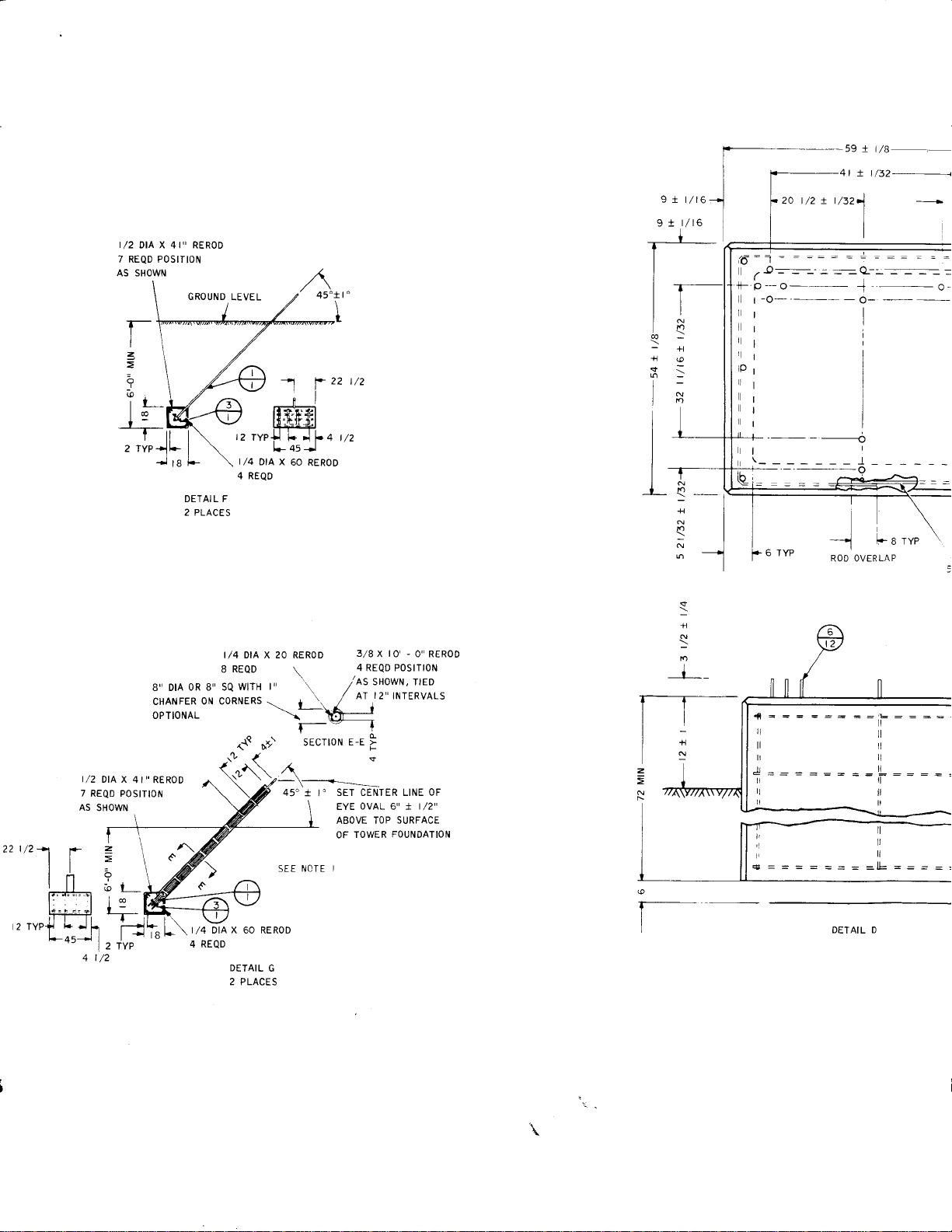
2.3 FOUNDATION AND
POINT CONSTRUCIION
The tower foundation and
first items installed
requirements
figures
mended
these items.
through a large
the
of
antenna
potential.
dc
routing
of
line cables
power
losses
and
For added convenience,
convenience outlet near the erecting
foundation
to unswitched
end
for
GUY ASSEMBLY ANCHOR
at
these
for
2-1 and 2-2.
configuration and layout information
(Reinforcing
The figures
conductor, as all
tower structure
Carefully
power,
control, and
to reduce
to keep
power
power
guy
the
cable cost at a
install
tool use.
cable
anchors are
Connect
at tower
site. Installation
items are shown in
provide
steel and concrete
recom-
ac and
the construction of these assemblies are
supplied
with the
antenna kits.)
the
any-
by
good
are
plan
a
the
for
for
not
2-7

tnstallatlon
It is imperative that
bolt locations be
with
and
guy
the
ment
guys
ing
anchors.
will
anci/or
and lowering
In constructing
the foundation
well
as absorb horizontal loads
erection
28-day
or
stowage
concrete
around foundations
In acid, alkaline
with
anchor
The
rods
concrete
blies should
erection
of the tower assembly.
guy
the
cause excessive
tower during antenna
the tower
can support
strength
or salty
bituminous
the
in
foundation
be aged at least
the tower base
in
Even a smallmisalign-
with
line
attachment
strain
each other
points
on the
rais-
operations.
foundation,
the tower
process.
is 3000-psi,
should be
installations,
soil
wrap,
The recommended
well
andanchor assem-
make sure
weight
due to the tower
Back
compacted.
14 days before
on
cover
as
fill
zontally and
loops
sheet
b.
A
be
foundation. This support shouldbe ofwoodwith
to within
1, detail
support for the bottomtower
placed
a large surface area. The
support
pivot
to form
should be above the leve1 of the base
shaft.
this
Assemble
position.
Attach
and right
It
tower
i.s
necessary to install the bottom
vertically with side anchor
+1/2 inch.
G.
about
(Wooden
support.)
15
crossties
See
sectionshould
from the tower
feet
top
surface of
may be stacked
figure
the tower in a horizontal
members to
pivot
vertical
assemblies.
horizontal brace on the inside of the
tower
vi.ew B-8.
as shown in figure 2-1,
sheet
the
2-1,
the
leftc.
2,
The side anchor
in the
be
planes
equidistant from
See
remaining five anchor
located
shown in figure
locate anchor
Iy can
and
lowering
ASSEMBLY
2.4
In
assembly
torque
limits:
3/8-inch bolts
1/2-inch bolts
3/4-inch bolts
a. Install the
of items
sheet
the nuts
level
14
same
as
figure
2-1,
at the
cause
buckle
the tower
operations.
OF THE TOWER
of the tower,
tower
10,
2) on the
on
tower
the
(figure
the tower
2-1,
Centerline of
terminating loops
vertical
and horizontal
pivot
the foundation
sheet
1, detail
points
distances
2-1, sheet
terminating loops
guy
cables
to overtighten
during raising and
use the following
pound-foot
25
pound-foot
90
pound-foot
320
pivot
assembly
11, 12,13,14,
and19;
concrete
the
foundation
pivot
assembly,
sheet 2) as a
pivot,
item 14,
MUST
shaft and
center.
The
G.
should be
and angles
1.
Failure
proper-
(consisting
figure 2-1,
foundation.
anchor
bolts to
using item
reference.
up hori-
Iines
to
Use
Place the
d.
support. Attach the lattice
two members
Place the third tower vertical member atop
e.
the
completed tower side.
f,
At either end of
erect lattice bracing
tower vertical members on the
bracingto
cross
the
completed
(four
in figure 2-1,
tower
braces) for the
as shown
third member.
o
h.
i.
j.
k.
I.
m.
and bolt the third
Lift
position.
Attach lattice bracing
to either
Lift third member into
place.
into
Attach
Attach tower
view B-B,) to tower.
Check
quately greased
greases:
aco
or
To
sheet
sheet
nut from cable
the center of
large
cable
tached, through
remaining
that
lattice bracing.
(item
1eg
winch
and
with
ANG-25; CPN
Unitemp; Beacon 325;
Super
attach hoisting cable
Mi1 ?2832
1) to
cable
winch,
2. Remove setscrew and
dog.
the
cable
hole in the
dog
setscrew,
hollow
with
the hollow axle of
vertical
member
end of
position
15, figure 2-1,
tackle block is
any of the following
005-0423-000;
Air
Shell
(American
(item
3, figure
see figure 2-3,
its
Insert
cable dog into
winch reel through
reel
core.
securing nut at-
the
sheet
side,
into
tower.
and bolt it
sheet2,
ade-
Tex-
No. ?A
Oit
Co.).
2-3,
securing
Insert
the winch
2.
I
2-2
Revised 15 JuIy 1971
4t
! t/32+
t/2+1
22
,r"r{
I/zDIAX4I"REROD
7 REQD POSITION
AS
[
t-L
*
1.,.
i, *l
L-lL
Lo.--,1 l
'-l
t/2
4
t/2
otA x 4r,, RERoD
7 REQD POSITION
AS SHOWN
z
=
o
b
SHOWN
z
=
o
bi
lo
t___
+
--1
I
2 TYP
GROUND
LEVEL
)M
,z
t/4
4 REQD
DETAI L F
2 PLACES
t
/4
REQD
I
oR 8" 5Q
B" DtA
cHANFER 0N C0RNERS
oPnoNAL
I t\
I,/4 DIA X 60 REROD
t*
re
4
wlrH
REQD
DETAIL
2 PLACES
A
'
45"
-l
4
rvelfL
DtA x
DIA X 20 RERoD
t'
-
!f
60
RERoD
\
r /
+ ,n
\-\&j
I-t
SECTION
45'
t I'
SEE NCTE
G
22
t/2
3/8
to'
x
0" RER00
4 REQD PoSlTloN
/'es
Ar
E-E >
SET CENTER LINE OF
EYE OVAL 6' t I /2"
ABOVE TOP
TOWER
OF
I
-
sxowN' ttEo
12"
INTERVALS
d
F
$
SURFACE
FOUNDATION
9 t r/16
r/16
91
N
S
+t
+1
I
:
I
N
l
n
l
I
I
I
I
I
NI
I
_1
*l
-l
nl
-l
N
6 --l
+l
N
l
t_
1--T---
tt
t-
i+
N
z
=
N
;--
I
,,6:1
I
l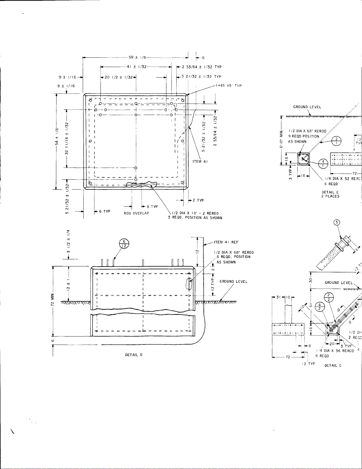
I
s
+t
i
l
I
I
I
9 t t/16
r/16
9 t
N
n
+t
I
:
n
>-i
+l
-t
nl
>t
ol
'l
zo trz t
trczl
+_b_o___J,_6-,
lll'
I
-!
I
I x t/32
1
r*,
,,,
t/2 )tAx
REQD,
5
2 53/64
I
l*,
lB' -
POSITION
!
-1---
n
,*
t
/32
+l
2 RERoD
AS
SHOWN
TYP
N
n
+t
@
o
l+45
t5
TYP
I
|
/2
z
9
o
@
lr-
lo
t_
L+
c
F
n
GROUND
)tA x
REQD POS
LEVEL
68,'
ITION
RER0D
t/4
DtA X
REQD
6
DETAIL
2 PLACES
52 RERC:
E
z
=
N
N
I
=-
I
+l
N
D
I
t_
ITE[,4 4I REF
I /2 DIA X 68" REROD
.8
REQD,
P0StTt0N
(-
3
++6
T-^
I
I
2 TYP
lq
6
GROUND
1.,' r\
/
't
-ln-J
otn
REQD
DETAIL
LEVEL
;JI
D]
l+\\
\ \
3 TYP\
x
56 REnoO
C
|
/2
2 REoc
Dt;
a
rlll
1l!l
lrll
J:::::=:--[
tlll
rr,ll
DETAIL D
F
N
I
GROUND
LEVEL
a,-l
r
r
L_
l*
'o

3rl
L-
r0
___r
72
li
JI
QTY
R EQD
SEE
DETAIL
F
\
d
n
{
q
a
\
\/"I
\
-,.
\,/
SEE DEIAIL D
6 REQD
DETAIL
E
2
PLACES
T
o
GROUND
?
LEVEL
SEE
j
z
@
NOTE
SEE DETAIL F,-
l\
__a_\/
a4',
ta
i-
_ i ,___)--
\
\
'*
,'-r\
.,. I
sEE DETATL E
325-O
A
PLAN
U..-
VIEW
-sEE
oETnrL
DETAILS
c
25.a
35.0
t/2
BENT
L
t/4
9 REQD
DtA x t4'-a
AS
SHOWN
/2
TYP+rP I
DtA
x
20 RERoD
SECTION
ROTATED
+
[sl
[a-----
45'
l+ r0 REF
i
N
i
D-D
CW
ANCHOR AND FOUNDATION
2 TYP
)/2
DtA
X t0'-0
RERoD
2 REQD
t
/4
I
DIA
X
6 REQD
l
t2
TYP
56 REROD
DETAIL C
/2 ltA x 68' RERoD
4 REQD P0StTt0N
ITEM
N0.
4
4
4
4
I
t2
3
I
I
2
I
I
I
I
I
6
t8
6
t2
I
I
2
I
9
I
I
I
2
2
I
8
4
4
B
3
3
3
3
I
2
I
2
3
4
6
7
I
9
t0
il
t2
t3
t4
t5
t6
t7
t8
t9
2A
2l
22
24
25
26
27
28
29
3t
32
33
34
35
36
37
38
39
40
4t
42
44
45

QTY
R EQD
4
4
4
I
t?
325.O
3
5
I
I
2
I
I
I
I
I
6
t8
6
t2
I
2
9
2
2
8
4
4
8
3
3
3
3
25.4
35.0
installation
PART
I
2
3
4
5
6
1
I
9
t0
il
t2
t3
t4
t6
t7
t8
t9
20
2l
22
23
24
25
26
27
2A
29
30
3l
32
33
34
35
36
37
39
40
4l
42
43
44
45
COLLINS
MBE R
NU
r
0
5-0856-000
0r5-t064-000
JIU-U)ZI-UUU
r
3
0-0523-000
766-2356-004
0r3-r324-040
432-r09r-000
766-2364-00
0t3-1891-040
766-2352-Aa3
1 66-2352-004
766-2362
766-236
-003
l -003
766-2366-00
-
2365
766-
766-2
003
367- 005
766-2354-O04
326-r53r-000
r 282-000
334766-23ss-00
t271 -AOa
334-
0r9-r313-000
766-2377
0
0r9-l3t
-Oa3
I 9-0279-000
t-000
0t9-0129-000
t 222-A2a
oa5-
I 5-2702-000
0
766-2369-00
I 2-000
332-07
338-0096-000
0t9-1314-000
r s-2352-000
0
0t5-4136-000
0r5-4t97-000
r
0
5-4235-000
I 5-2354-000
0
0t5-4r39-000
0t5-4r98-000
r
5-4237-000
0
-2448-000
t
42
788-6275-00
42r-r020-000
774-633r-001
-0994-OO3
3
or
DESCRIPTION
ROD,ANCHOR-34XIOFT.
ROD,ANCHOR-IXIOFT.
WASHER-4X4Xl/2THK.
WASHER.6X6X3,/8THK.
BRACKET,
BOLT,
WINCH
ANCHOR
STRAND,GUY-38(FT)
I
I
UPPER
GUY,
SECTION,
LEFT
PIVOT,
RIGHT
PIVOT,
BRACKET,
BRACKET,
PIVOT
SHAFT,
LEG. TOWER
ROTATOR
PLATE,
BRACKET,
scREW,
TOWER
BASE
CENTER
LOWER
CAP
NUT.HEX.-34.I0
U -BO
LT
r
NUT.HEX.-3E-16
JUNCTIOIT
BOX,
CONDUIT-NIPPLE
ARM,
NUT,
BREATHER,
LOCK
-
CONDUIT
CONDUIT.34X
COMPOUND,
KIT, STRAPPING
-
CONDUIT
I
3
PLUG,PIPE-34
COTTER
PIN,
JUNCTION
BOX,
STRAND
GUY,
TURNBIJCKLE-58X12
SHACKLE
THIMBLE
GLY,
TURNBUCKuE-34XlB
SHACKLE
THIMBLE
WIRE, ELEC
I
5TRAP,
WIRE
INSTRUCCLAMP,
-
-
STRAND
.
- I 2
GROLi\i]INC
{FT)
O\
HOSE
3 t
5 3
-
4 - l0 X2
3
3.1
IOFT.
SEALING
4
.
DEAD
2
.
DEAD
IFT'
;.ATE
(TUBE)
ENO
END -
NOTES:
LOWER SIDE
I.
2. IN
3. EARTH
4. IN
5.
l.tz
6. SAFETY
WITHIN
SHAFT
HORIZONTALLY
AND
ACID,
ANCHOR
SHOWN
ALL SPLIT
AND
ITEM
LEVEL
TOWER
I/2 INCH
HOLES
FORMED
ARE
ITEM
USING
7. ANCHORS
TOLERANCE
8.
9.
IO.
I I. END
FIE O
CI
SPE
OVERALL
OTHERWISE
LACING
VIEW
MAIN
LOWER
OF
WITH TUBE
OF CABLE
I INCH
I2. COAI
.
3.8
I3.
ALL
4I
ITEM
ROD FOR
SUITABILIW
STORMS
I4. GROUT
I 2
AFTER
ANCHOR
GUY
OF
IN BASE
ALKALINE
WITH BITUMINOUS
RODS
ANCHORS
PREFERRED
BALLOONS
BOTTOM
I4
BEFORE
ALL TURNBUCKLES
WIRE
ITEM
FOUNDATION
AND
ON FRACTIONS
OIMENSIONS
SPECIFIED
TOWER
OF
AND VIEW
GUY BRACKET,
SECTION
SHOULD
EXPOSED
CONDUIT
REF, TO
LIGHTNING
DEPENDS
AND GROUND
UNDER
SPACE
LEVELING
LINE
BRACKETS
OR SALTY
FIGURE
43
ON CONCRETE
MUST BE
B-B
AS SHOWN
THREADS
BE CONNECTED
AND STATIC
ON FREQUENCY
CONDUCTIVITY
BRACKETS,
MUST
LOOPS
PASSING
SOIL
WRAP
TO MINIMUM
TOP FIGURE
IS
QUANTITY
RAISING
DESIGIIED
I,/4 UNLESS
t
ASSEMBLED
INSURE
TO
I7. ORIENT
ITEM
IN SECTION
VISIBLE
BE
WITH SEALER,
BE
THROUGH
ITEM
COVER
DIMENSIONS
IS MATERIAL
TOWER
AFTER
FOR 3OOO
ARE
PROPER
WiTH
SUITABLE
TO
DRAIN
OF
ITEMS
LOCATED
PIVOT
I2, VERTICALLY
EXPOSED
LIST
PLUMBING
PSF
OTHERWISE
OPERATION
ITEM
A-A
27
ITEM
GROUI'ID
ELECTRICA'L
I3
8104
UNLESS
IN
I7
564
MINIMUM
AS SHOWN
A MINIMUM
PROTECTION.
I2 AND
SOIL
OF
6
IT EM
N0.
I
I
I
I
I
I
I
I
z
Figure
Revised 1
2-1"
Anchor and
(3000-PSF
December 1975
Foundation
(Sheet 1 of
Soil)
Details
2).
2-3/2-4

I
D
\ta/ lo
IIX|.J
-
_l
THIS ANCHOR
PLACE ONLY
I
ROD
\^
/'_\ 4
A )o) v-
\::Y-r*-JL.S
\\
rl
LIGHTING
PART OF
(OPTIONAL
N0. 515-8453-001
PART
\f\
EQUI
\.cV
\:\
-/
\.:\
_.t\
DETAIL
PLACES
3
P)
(
6iK--
-
A
KIT
COLLINS
sEcTtotr A-A
rF
II
le
ITEM 4I
IIOTE
SEE
REF
I3
t/2
20
B.B
VIEW
SEE NOTE I O
.E NOTE 12
DETAIL A
SEE
(2
ANCHOR RODS)
DETAIL E
SEE
t/2
t
_/
SEE DETAIL

inst
allation
i-
I
\
)
!1E!t-9:9.
ROD
ANCHOR
THIS
I PLACE ONLY
DETAIL
PLACES
3
PART OF LIGHTING
(OPTIONAL
PART N0.5r5-8453-001
SEE NOTE
SEE DETAIL A
(2
ANCHOR
KIT
EQUIP) COLLINS
12
RODS)
SEE NOTE
A
DETAIL B
PLACES
4
DETAIL B
SEE
I I
€
,EE
i
't
-j
,
NOTE
4 I
ITEM
sEE iloTE
REF
13
20 t/2
vtEt/Y B_B
SEE tiOTE
tt/2
IO
DETAIL B
SEE
SEE DETAIL
ELEVATION
?
PLAN VIEW
\;-
Figure 2-1.
sEE DETAIL A
Anchor and Foundation
(3000-PSF
Soil)
(Sheet 2 of.
Details
2).
2-5/2-6

I
N
n
+l
@
:
n
4'-lrJl.8
tl
4l
@
>
+1
o
-
n
+l
o
o
PT-A.
/^ I
\
"o,-.
c \ t.
l.)o)*:,
I
,?o
,O
ur".
>-_
''ti'-=t{*f
-ci
,.\
*o\
d-q') I
'i'--f--(o
/32'
J
o
OF
F<
o
I
-,,
\
-,+)
tu"__{-,uV
,"ykJ*
|
I
/".,
"
-n
\"
--
-,'-<
..6-
P.
50'r3"
EYE
/42
OVAL
I\
Ai F.2
1-
(TYP,)
2 53/64!l
_5
2t/32tt,j?_ l\P.
o
''-
V
n
rl
@
+l
N
m
3
N
ll
NOTES
Dta
3/4"
ANCHOR
n
o
j
BOLTS
CHAM
N
a
n
N
n
_\
N
FER
-..
;
I
L__
3'. Ct.
I
I TYP.
l_._L4
o<
FJ
llo
bu
o>
I
N
n
t]'I
_
4L
WiRE
REF
NO.2T
25 ELEC
ITEM
u
I
THRU
,
DIA
---,1
;
!lOLES
ANCHORS
I
(2E.W.
IN
/.r'
r0
N0.
WINCH
BRAC KE T S
)
{+
/
t'"( I
I
4 E.W.
L,.
4-N0.4-6"X36
POSITION
N0.3
BR ACKE T
AT 24',1
f--
].--
r-"
xxi
- N0.
4
4n E.W.
FINISH
GRADE
N0.
3UAr 24"1
N0.
3 AT
I
16 NO.
SIDE BARS ACROSS ENDS
NO. 3L.J AT 24"1
25,
24"1
4 - BSND
ELEC W]RE
TE[/ 4i REF
ALT.
E LEVATION
FOUNDATION F-
DETAIL D
6'X6"X3l8"
WA
SHERS
I
2',-C"
X t0'-0,,
ELEVATIOI\
FOUNDATIC
DETAIL C
\

f\ P
I
53/64+
/32
2t
/32].t,82
I
I
I
LJ
-T----
f^
J_\
l{1
rp
!n-
16
!N
1
:5 ELEC
TEIVl
-
,4
FINISH
r-l"yx-ge'--
-
lto. s nt
I6 NO. 4
SIDE BARS ACROSS
'N0.
25
\
I-TEM 4] REF
'
so'tr
gyal
6yg
W RE
4I REF
N0.
4n E.W.
GRADE
NO. 3U AT 24,,1
24,t
.
BEND ALT.
ltl Ar 21't
ELEC WLRE
, AT
,
F-2
ENDS
x 6"
6'
WA SHERS
(TYP,)
x
3/
I
o
9
lT-
I]
i
t-
lZ)
I'
l+
lt
il
+i
li
l.__
4 - N0. 4 - 6"
POSITION
BR ACKE T
N0.3Ar24t
I
o
i
3'
cr.
I
tl*o'
i
L
2'_0"
THRU I]OLE5 IN
I
r-
I
I
L-
t-
I
L=3
2',-0"
x t0,-0,
__.1
X 36"
.
DIA
-T
)
,l
I'DIA
(2
ANCHORS
I
I
/r"
)
a
t0 N0.4
WINCH BRACKEIS
ANCHOR
WINCH
BR
E.!v.
/:,,.
;rLl
E.w.
NOTES
ALL
IN
t.
AI\D
IlEfuI
iTE\4
AiL
?.
TIGURE 2-I SHEET
Tc
NO. 2
TIES
2
ACKE-T S
r.
l,
.3JAi
_-
8'-0 x 2,-0
E LE
VAT ION
FOUNDATION F-3
C
OETAIL
t]ALI-OONS
SPLIT
BOTTOI\1
NI]I,'lBERS
AT IB 1
4
N0.
.1
)
<,/"'(\
'
/.>l
\$l
zal
.ldl
'\.i
l
l1'llr
r
--]-
tl
lrl
i--
1--
aaa
24
TOP FIGURE
IS
FIGURE
AND DEiAIL REFERENCES
I
AI
IOO T3"TO CENTER
le.
9., >
,
-YJ
---J
't
I
-
--l
-
l-
IS
QUANiIT\
2 PAGE'., 2--7/2
T
riz
B
-
-|
r---+
!
I,IAiERIAL
REFER
1
LINE F-I
J
I
-T
L',<i
-_I
a
N
I
l
FINISH GRADE
/
FINISH
GRAD
4" \4' X
WASHE R
6'X6
WASHER
X3l8'
E
4 NO. 3
,*to-rri.
',
N0.3AT24t
/2'
EXTEND
\[--1
*, + N--l
-L[q!J
CHAMFER
8"7
\_
NO,2
H AIV]FE R
C
\
TIES
T-
f-
I
,,'
I
L
I
I
I
3'-o'
l-
ELEVAT
ON
FOUNDAT
ON
DEIAILF_2PLAC:
DETALG_ZPLAC
I
DIA
4',-0
ELEVAT
FOUNDAT
DETAIL E-2
-_
x 6'-0'
F_2
ANCHOq
x 6
ON
ON
-0
F- 4
PL:
Figure
2-2.
Revised 15
July
Ar
(1
19

4NO.3EX
I
2
lNTo F'
TEND
TG.
tr
C H AIVIFE R
T0 REF.
50 13'
PT. A AT F.I
3/4,,DIA ANCHOR
rnstallatt;on
I
L
o
I
INISH
_/
GRADE
FIN IS H
cnnog\
t'vAS:ER
\
N0.
N0,3
b
3
CHAI\,4
AT
AT
24',r
NO.2
24
t
FE
R
i-
t-
L,'
l-J
r.J
i*-.
ELEVAT
FOL,NDATIoN
DETAiLF-2PLACES
DETAILG_2PLACES
f-
TIES
/_
. ,.-o
ON
F-2
CHAM FER
t7
---]'
q,
NOTE
IO
NO.
SIDE
BARS
N0,
3UAT
3'CL. TYP._
IOOIt3'
q.
16 NO.4 -
SIDE BARS
N0.
SET CENTER LINE
OVAL61I,/2 ABOVE
TOP SURFACE OF
FOUNDATION
CASE
ANCHORS
DETAIL
G ONIY
-
4
BEND
ACROSS
24"1
TO CENTER LINE F-I
1r
o
{
[
---/
3L_l
AT
AT
CENTER
ENDS
rrrursn
caaor
BEND ALT,
ACROSS
24"1
TOWER
ENDS
OF EYE
X6
6
WASHER
X3l8
t_
Figure
Revised
t
ELEVAT]ON
FOUNDATION
DETAL
4
-0"
E-2 PLACES
2-2"
15
JuIy 1971
x 6'-0"
F-
4
Anchor
(1000-PSF
_l
n
I
and
Soil).
Foundation
B
04
Details
2-7
/2-8
705
6

QIY
REQD
4
2
4
2
2
4
M
ITE
N0.
I
334-
0r5-2r28-000
I
I
I
I
I
I
I
I
I
2
4
5
6
7
9
t0
I
t2
r3
t4
l5
r6
t7
764-7259
0 |
0r5-4r98-000
ot5-086t-oo0
ot
at5-42a7-OOO
766-235
326-124t-OOO
76A-244s-OO
766-2446-OO3
764
333-0444-000
326-2293-OOO
3
PART
COLLINS
NUMBER D ES CRi PTI ON
r 279-000
-40 t
5-2364-000
5-2354-OAO
I
-O05
-7262-OOt
NUT, SELF.LKG-
WINCH,
CABLE
HOISTING
CABLE-
TACKLE
BLOCK,
SHACKLE-
wlRE
cltP,
DEAD-END.
THIMBLE.
MAST, ERECTION FIXTURE
scREW,
t
CAP
BRACKE T
COUNTER
HANDLE, EXTENSIOiI
NUT, HEX -
scREw 5/t6
ro-0762-Or0
WASHER, I/2
SEE
I,/2-I3
5/8
-t/2
ROPE
GUY.STRAND.
I/2
- t/2-t3X2
WEIGHT
5/t6
-
- rSxr
DETAIL
B
t8
3/8.
I/2
SEE
NOTE
4
NOTES:
I.
IN ALL SE
2.
GREASE
5 .2.2.
3. TO ATTAC
CABLE DC
HOLL0Yr
H0t.L0\,,
T HE LIF-i
HOLE IN:
T HR 0
CABLE DC
(200
WARIIINC:
4.
REFI.]SE]
CAIJSI\G
5, DRIVE EX'
E. LOCATE
(ASSUT'lrI
BLOCK, I-
CLIPS, IT
WARNIN
WITHOU
cAUTl0l\:
8.
ri
6r-r
PcL'
,'
!
I
i
G,
i
IT SHOUL:
El\'4ERG Er'
ITEM 3
'e@
EXISTING
CABLE
TOWER
SEE WARNING NOTE
CETAIL
SEE
q+-
DETAIL A
@
DETAIL
AFTER ERECTION
VIEW
A
GREASE
FITTING
Rev,

t'nstallatlon
NOTES:
I. IN ALL SPL.IT BALLOONS,
2. CREASE
3. T0
4.
WINCH AND
ATTACH
CABLE
CABLE DOG
HOLLOW
HOI.LOW AXLE OF THE
THE
HOLE IN THE
THROUGH CABLE DOG.
CABLE DOG
(2OO
WARNING: ONCE THE DEAD-END, ITEM 7, HAS
REFUSED. REUSE
CAUSING DEATH OR INJURY TO PERSONNEL AND DAMAGE
INTO THE CENTER
REEL
CORE
LIFTING CABLE THROUGH THE SMALL
CABLE DOG,
(I5O
POUND FEET).
5, DRIVE EXTENSION
6. LOCATE DEAD-END, ITEI\,4
(ASSUMING
BLOCK, ITEM 4, AND
CLIPS, ITEM 6.
WARNING: D0 N0T ATTEMPT
WITHOUT
CAl.lTl0N: THE
8.
IT SHOULD
EI\.4ERGENCY
LEVEL
COUNTERWEIGHT.
WINCH BRAKE lS
NOT BE USED IN
BRAKE, APPLY FORCE SLOWLY
TOP FIGURE
PULLEY, ITEMS
T0WINCH,
INSERT CABLE DOG
WINCH REEL AXLE
ALLOWING APPROXII\,'lATELY SIX INCHES
TIGHTEN SET SCREW
POUND FEEI). TIGHTEN
IO 2OO
A DEAD-END
OF
HANDLE, ITEM
7, SO THAT TYE IS
GROUND).
PULL
UP
NORMAL LOWERING OF THE ANTENNA. IF USED AS AN
IS ITEI,l
2 AND 4 USING GREASE CALLED
SEE SHEE'r
OF THE CABLE
SET SCREW
AND
RESULT
CAN
I4, ONTO SHORT BRAKE
EXTEND CABLE,
TENSION BEFORE
T0 RAISE ANTENNA
AN E[IERGENCY BRAKE 0R STATIC H0LDING DEVICE.
NO. AND
BOTTOM
FIGURE IS
QUANTITY,
OUT IN PARAGRAPH
2, RElrovE SCREW FR0t\,1 CABLE D0G, INSERT
TVINCH REEL THROUGH LARGE HOLE IN THE
WITH
SECURING
LOOSELY INTO CABLE DOG. INSERT
SCREW
HOLE
THE REEL CORE AND THROUGH THE
IN
UNTIL CABLE IS TIGHTLY SECURED IN
CABLE DOG
BEEN INSTALLED
IN SLIPPAGE
TO
HANDLE
NUT THROUGH THE
OF
CABLE
SECURING
IT
SHALL
THE
OF
EQUIPMENT,
OF ITEIVl
TO EXTENT)
NUT TIGHTLY
NOT BE
DEAD-END
2.
I34 FEET FROM UPPER END OF GUY
ITEM 3, FROM WINCH, ROUTE THROUGH
ATTACHING TO ANCHOR WITH ROPE
WITH U/INCH/BLOCK AND TACKLE
TO PREVENT SUDDEN STOPS.
@
SEE DETAIL
A
SEE NOTE 6
lfne'e"'
ELEVATION VIEW
Figure
2-3,
Revised 1 December
NOTE 6
Installation
(Sheet 1 of 2).
1975
.i/
Blo4
of Erection Kit
2-e/2-L0
668
4

inst
alla
f---
o
I
ADAPTER
SEE DETAIL
errurolr
@
A
sHowN
paRTrALLy
INSERTED
DETAIL
CAELE
II{SIDE
A
ENO L
WINCH
DRUT
SECURING NUT
QIY
REQD
CABLE DOG
OT
N
I. REMOVE ANCHOR ADAPTER
REEL
3.
Figure 2-3.
SET SCREW
ITEM
COLLINS PART
N0.
NUMBER
I
I
I
I
ES:
CAUTION: CHECK CONDITION OF I/4 20 X 3 SCREW,
ITEM
DRI
CAUTI0N:
POSITION ONLY
PINION BY A SPRING
CAPTIVATED
758-529 r
2
or5-3049-0r0
4
326-2274-OAa
5
333-O428-000
AND
ITEM 2
CABLE WINCH,
4 AND NUT,
VE R.
-00 I
REPLACE WITH ITEMS
ITEM 5 BEFORE EACH
POWER
USE
(PINION
LOADEO DEIENT). PINION
IN LOW RATIO
Installation
(Sheet
2
of.2).
NOI'ENCLATURE
DESCRIPTION
ANCHOR ORIVER
P INION
scREw-
t/4-20x.
NUT,SELF.LKG-I4
FROIlI ANCHOR
3,4,
USE
TOOL lN HIGH RATI0
IS CAPTIVATED IN
POSITION.
of Erection
DRIVER
AND
PlNl0N
HIGH RATII
OR
ASSY
AS
5 TO
OF ANC
IS NC
Kit
z-LL/2

installation
I
--___!
I
)
,
ANCHOR
6)
6',
SEE
PrNloN
DEIAIL
O
A
sHowN
PARTtaLLY
INSERTEo
l.IIGH
RATIO
PINION POSITION
(
SECURING
I\IUT
@
CABLE DOG
Figure 2-3.
5ET SCREW
!TEM
QTY
REQD
NOT
ES:
I.
REI\,IOVE ANCHOR
ITEIil 2 AND
CABLE
2.
CAUTION:
ITEM 4
DRIVE R.
3. CAUTI0N:
P05tTt0N
PINION
CAPTIVATED IN
COLLINS
N0.
2
3
4
5
WINCH.
AND
0NLy
BY A SPRING
PART
NUMBER
7
t -OO I
58-529
015-3049-Ot0
326-2274-OOa
-0428-000
333
ADAPTER
REPLACE
CHECK
CONDIIION OF
NUT,
ITEM
POWER
USE
(ptNt0N
LOW RATIO
Installation
(Sheet
2 of.2l.
ANCHOR
P
scREW- t/4-20X3
NUT, SELF-LKG
FROIU ANCHOR
WITH
ITEMS
5 BEFORE
T00L
lN HtcH
ts cApTtvATED
LOADED
DETENT).
POSITION.
of
Erection
NOMENCLATURE OR
DESCRIPTION
DRIVER
INION
DRIVER
3,4, AND
I/4
20 X
SCREW,
3
EACH
RATTO
tN HtcH
PINION
UsE
ptNtON
OF ANCHOR
Kit
ASSY
-
-
I'4
?A
ASSY,
5 TO POWER
RATIO
IS NOT
2-1L/2-L2
rnstallatlon
reel and screw
Insert one
the small hole
the hole in
mately six inches
cable
drum.
until cable i.s
(tighten
dog
torque
screw
Do
or
ReeI a minimum
reel before
hoisting cable.
cable
the
Attach counterweight
block
erecting
weight will allow cable
ravel
value).
to
a
not stand
lowering
will
not be
hole.
and tackle
tower. Failure
the
and
loosely into
end of the hoisting cable
in the reel core and
the
Tighten cable
tightly
to
Tighten securing
torque
under
the tower.
applying
dog, allowing approxi-
cable
of
cable
150- to 200-pound-feet
a
value of
torver
two turns onto
of
any tension
This ensures
damaged by the edges of
to
prior
tower to drop.
the
to
extend
dog setscrew
200
when
in the cable
rarsrn€l
secured
that the
erecting
to its use in
to use
preform
counter-
cable
dog.
through
through
inside
nut on set-
pound-feet.
the
to the
winch
to un-
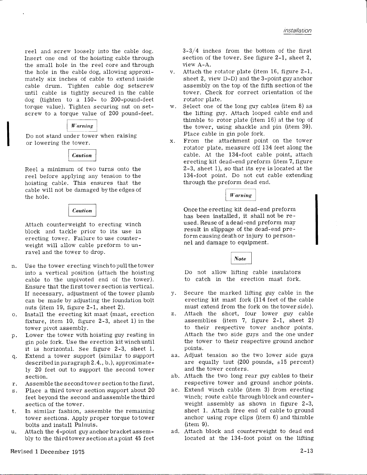
3-3/4 inches from the bottom of the first
section of
view
Attach
v.
sheet
assembly
tower.
rotator
w.
Select
the
thimble to rotor
the tower.
A-A.
the rotator
2,
view
on
Check
plate.
one of
lifting
plate
D-D) and the 3-point
the top of the fifth secti.onof
for
correct
the
long
guy.
Attach
plate
the tower, using shackle and
pole
gin
in
measure off
the 134-foot
dead-end
that its
point.
Do not
preform
kit dead-end
of the dead-end
death or injury
to equipment.
x.
Place
From
rotator
cable
the attachment
plate,
cable. At
erecting kit
2-3,
sheet 1), so
134-foot
through
Once
has been installed,
used. Reuse of adead-end
the
the erecting
result in slippage
causing
form
nel and damage
figure
See
(item
guy
looped cable
(item
fork.
point
cable
preform
eye
cut cable
dead end.
it shall
2-1,
16, figure
orientation
cables
16) at the top of
pin
on
134 feet along the
point,
(item
islocated at
preform
be re-
not
preform
person-
to
sheet
2-1,
guy
anchor
the
the
of
(item
8) as
end and
(item
39).
the tower
attach
7, figure
the
extending
may
pre-
2,
n. Use
the tower erecting
into a vertical
cable
Ensure that the first tower section
If
can be
nuts
to
necessary,
made by adjusting
(item
position
the unpivoted end of
adjustment
19.
figure
o. Install the erecting
fixture, item
pivot
tower
p.
q.
Lower
gin
it is
Extend a
des
ly
section.
the tower
pole
horizontal.
cribed
20 feet
r. Assemble
Place
s.
feet bevond
secticn of
a
10, figure
assembly.
fork. Use
tower support
paragraph
in
out to
the s
econd
third tower section
the second andassemblethethird
the tower.
winchtopullthetower
(attach
of the tower
the foundation bolt
2-1, sheet 2).
kit mast
2-3,
with
hoisting
the erection kitwinchuntil
figure
See
(similar
2. 4., b.), approximate-
support
tow er
the second
ection
s
support about
t. In similar fashion, assemble
tower sections. Apply
bolts and install
u.
Attach
bly to the thirdtowersectionatapoint
the 4-point
proper
Palnuts.
guyanchorbracketassem-
the hoisting
the tower).
is vertical.
plumb
(mast,
sheet
guy
erection
1) in the
resting
2-3. sheet 1.
to support
tower
to
the first.
remaining
the
torque
totower
45 feet
20
in
Do not a1low
to
catch
Secure
v.
erecting kit
must
z.
Attach the short, four lower
assemblies
the marked
extend from
lifting cable
in the erection
lifting
mast
(item
(114
fork
the fork on thetowerside).
7, figure
to their respective tower anchor
Attach
the
points.
aa,
Adjust
are
and the tower
ab.
Attach
respective tower
Extend
ac.
winch; route
weight
sheet
anchor using rope
(item
ad.
Attach
the
tower
tension so the two
equally taut
the two long rear
assembly as shown
1.
9).
block and
located
two side
to their respective
centers.
winch
cabie
cable
Attach
at the 134-foot
guys
and
(200
pounds,
guy
ground
and
(item
throughblockand
free end of
(item
clips
counterweight
point
insulators
mast
guy
feet of the
fork.
cable
Cuy
in the
cable
cable
2-1, sheet 2)
points.
the
ground
lower
+15
cables
anchor
3) from erecting
in
cable
6) and
on the lifting
under
one
anchor
side
percent)
to their
points.
counter-
figure
ground
to
thimble
to dead
guys
2-3,
end
Revised
1
December
1g?5
2-13

tnstallatron
guy.
Pull
up slack in the winch
guy
cable.
winch
The
two wraps
taining
to the
will
cable
of
the
hole.
Do not stand
or lowering
must
of
cable
hole
before tension is applied
cable. This
not
be
under tower
the tower.
ae. The builder should
and
installation by erecting and
tower
prior
to installation of the rotator,
array and accessories. To
1. Ensure that all
to the upper
attached to the
2.
Be sure
two
side
shaft) and the tower
guys,
side
that
the tension is
guys (in
and
have a mi.nimum
past
the
cable
ensures
damaged
the towerassembly
check
except
of the
lowered tower, are
correct anchor
line
that
by the
raising
when
lowering
erect
thoseattached
equal on the
with
edges
the tower:
facilities.
is centered.
re-
the
the
lifting
of
the
pivot
Meropa
Check
greased
to
ANG-25; CPN
No. 7A; or
Oil
Co.). See
1
No.
see
with
or
that the
of the
any
005-0423-000;
Super
Ml1. 72832
section 5 foralternateoils.
005-1269-020.
CPN
rotator has been
following
The rotator heater kit is recommended
for operation
below +10'F
where
(-12.2"C).
temperatures fall
See
figure 2-5.
If the rotator heater kit is not used and
temperatures
+10oF,
drain
are
rotator
Motub-Alloy Artic Gear
Oiland Grease Co.,
Los Ange1es, California).
a.
b.
Install the
figures
InstaII
on the
2-7 and
rotator to the rotator
2-4
and
the
rotator
gear
case. See
read
expected
oi1
6505
2-6.
motor
pertinent
to falI below
replacewith
and
OiI
Wilshire
andswitch assembly
figures
emphasis notes.
greases:
Air
She1l
(American
(Imperial
Blvd.,
platform.
2-4,2-6, and
See
Vvvl
The back
come
3.
Use the
fork of the
pull
4.
Check
vertical
adjust
5. Adjust
percent,
200
assemblies.
6.
Lower
procedure.
the
array and
INSTALLATION OF ROTATOR KIT, CON'TROL
25
KIT AND RF
Before installing
gearcase
plug (approximately
gallon).
a
guy
assembly
taut
before tower is
upper
g".ry
must not be-
fully erect.
cable assembly
tower erecting
the tower
the tower
(x1/2
the
guy
on
pounds,
the tower
base of the tower in order
up to
inch).
guy
turnbuckles.
tension to
the
upper
percent,
*15
by reversing the
Place
a support 60 feet
an erect
to be
sure
If out of tolerance,
1300
guy
assemblies,
on the
support the lowered tower.
TRANSMISSION
the
with
oil up to the
LINE
rotator
seven-eighths
figure 2-4. lJse
See
ki,t mast), to
KIT
oil ievel
(in
position.
that it
pounds,
lower
erection
to
clear
filI the
of
Texaco
the
115
and
guy
from
the
motor drive key slides
If
wedging results. Motor must fit freely
rotator
into
with thread
recess. Coat
lubricant
toward
mounting bolts
and insert and
motor,
tighten to 25-pound-foot torque value.
Install the
the tower.
of
is
facility J-box at each end and
place
in
conduit
with
figure 2-1, sheet
on the hinged, lower side
The conduit has
a
is
the steel straps
2)
furnished
with the tower
clamping
fastened
(item
28,
kit.
(45),
d.
Attach
the breaker box
rotator control box, item
figure
See
Use a
cable
2-7.
fish tape
assembly through
at both ends using the
the
f.
Connect
electrical
in the J-boxes and
switch assembly.
o
h.
the obstruction
If
stalled,
Apply
see figure
power
and operate
facility on the rotator
that the rotator functions
rotator with the key
person
a
and
standing
facing the rotator.
pull
to
the rotator
the
cable
wires
to the rotator motor and
figure 2-7.
See
lighting
2-8.
controlJ-boxtoensure
slot located
at the top end of
item 20, and
2, tothetowerlegs.
control
conduit.
clamping
to theterminals
kit is
the
properly.
C1amp
J-box.
be in-
to
local control
the
Stop
to the left of
the tower
it
2-14
Revised 1
December
1975
rnstallation
i.
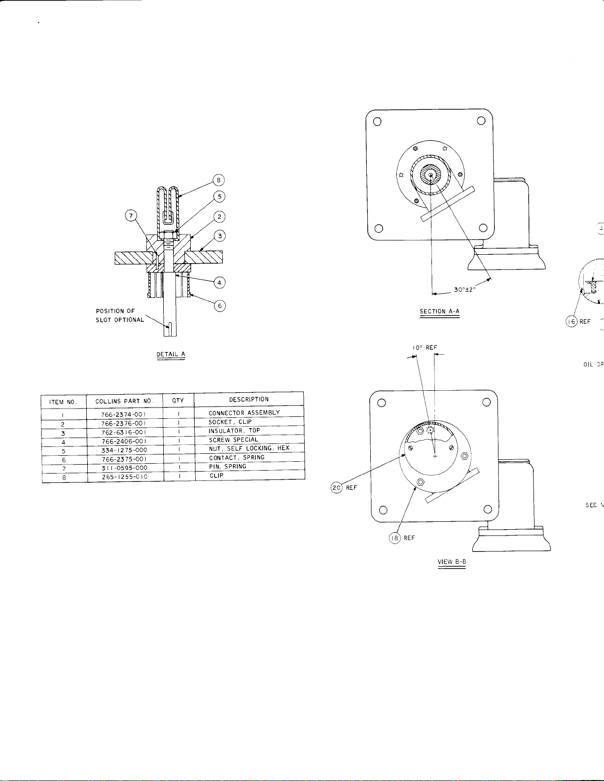
Attach
input
the rf transmission
the rotator.
of
inch reducer
1
506-000 and 01 3-1
transmission
2 and 3.
Strap transmission
straps
(item
Use a 3-l/8- to 7-Sf8-
and a
coaxial elbow
30 1-020) furnished
line kit.
See
line to the
figure 2-9, items
coaxial
(CPN
with
013-
the
Use O-ring supplied with reducer.
line to tower with steel
28, figure 2-1).
Revised
1 December 1975
2-L4A/2-t4B
POSITION
OPTIONAL
SLOT
,,.
-
(*-
,lb-t
'-r-
OF
qljAlll
i O"
SECTION
:
REF
A-A
I
(.]
/
s) ner
tTEl\,1 N0 .
I
2
3
4
5
6
7
B
PART
COLLINS
7 66-2374-OO
756-2376-00
-63 I 6-00
762
7
406-00
66-2
334-r275-000
766-2375-00
-O595-O00
r
I
3
t255-O
265-
NO QTY
I
I
I
la
DESCRIPTION
SPECIAL
SELF
SPRING
ASSEMBLY
CLIP
TOP
LOCKING,
SPRING
HEX
VIEW
:
B-B
I
CONNECTOR
SOCKET,
INSULATOR,
SCREW
NUT,
CONTACT,
PtN,
C LIP

SEE
DETAIL
A
SECTION A.A
REF
I O"
VIEW B.B
OiL
SEE
REF
DRAIN
SEE NOTE 4
SEE NOTE
SEE
NOTE
OIL LEVEL
SEE NOTE
PLUG
PLUG
7
REF
6
At_
5
NOTE
9
SEE NOTE
Bt
CROSS HATCHED SECTION ROTATED 6O'
CCW
-00t
A5 VIEWED FROIU BELOW
IO
1_JA
\T:,a
'l
-->@
)-i\
a?
@see
u
+
r,B -o',
-@
tt' *0"
r.rore
SEE
z
NOTE
'
3
Revised
August
1
1l
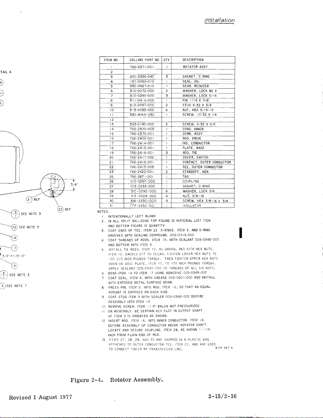
t nst
al
I
atl
on
A
TAIL
D
E
:\
,
\
l
-re
.--o
f
+
3,6,,
(,
a\
sEE
i
srr rtrore
Q
SEE
sEE NorE 3
ra
-0,
r
NoTE
3
z
NOTE 3
T
3/4'
_t
ITEM NO COLLINS
I 766-237 t
2
3
4
5
6
7
9 3
0
2
3 343-0
4
6
7
8
9
20
2t
22
23
?5
?6 0 5-0257-000
27 or 3-0233
28 310-0292-OOO
29 3
30
3l
NOTES:
I . INTENTIONALLY
IN ALL SPLIT
2.
AND BOTTON,,I
ENDS
COAT
3-
GROOVES
WITH
4. COAT THREADS
AND BOTTOI\,1
TIE RODS,
iNSTALL
5.
6, BOND
7
8
9 COAT
O
I2.
13, ITE]\4S 21
IC, BACKED OFF
ITEN']
IOO tIO INCH
DO\\,N ON BASE PLATE,
APPLY SEALANT
ITEI\,4
SEAL,
COAT
EXPOSED
WITH
PRESS PIN, ITEM 8, INTO
AN']OUNT IS
STUD ITEI\,1 9
ASSE]\1BLY INTO
REI\,4OVE SCREW,
ASSEMBLY, BE CERTAIN
I ON
OF ITEM 5
ROD, ITEI\,1 6, INTO
INSERT
ASSEMBLY OF CONDUCTOR
BEFORE
ANO SECURE COUPLING,
LOCATE
FROI\,1 PLAIN
INCH
ATTACHED
TO
,28,29,
CONNECT
PART NO.
-00 r I ROTATOR
-040
-2338
2 00
r
37-0083-0
990-0927-0
3
3
3
330-4053 - 530
766-23 70 -003 COND, INNER
766-2374-OO CONN,
7
7
7
7 66-24 6-00
7 66-24
766-24 8-00 r CONTACT, OUIER CONDUCIOR
7 66-24 9
766-2422-40
766-?a7
325 -2330-OOO
774-6332-OOl
OF TEE,
-000
0-0072
0-0290-000 3
-04 r
-000 l PtN r/r6 x 3/a
9
-000
-0097
2
3-0033-000 6
r
90-000
66-2405-04
4-00
66-24
-O0
66-24 5
-O02
7
-003
-OOl
-OOO GASKET, O
L3
-
O004
BLANK
LEFT
BALLOONS
IS
FIGURE
ITEI,4 22,
SEALING
OF RODS,
ITEI\,1 5,
INTO
ITE['1
TO CLEAR,
TORQUE.
POUNDS
OO5-054i-T
I4 TO ITEM
WITH
ITE1\,1 4,
EXPOSED
IS ORIENTED
TO OUTIR CONDUCTOR TEE, TE[4
Ni]ETAL
ITEIM
ITEM
END OF
1O\\IR
SURFACE DOWN,
ON EACH SIDE.
WITH SEALER
I8
AND
RF
QTY
3 GASKET,
I SEAL, OIL
r 0
r
I
0
2
2
I scREW, r0-32 X l/4
2
r
r ROD TIE
t STANDOFF,
2
6 WASHER, LOCK
-000 6 NUT,
6
FIGURE IS
TOP
QUANTITY
O-RINGS, ITEM 3,
COI\,IPOUND,
I9, WITH SEALANT
ITEM
I9,
AS SHO\\N,
THEN TIGHTEN UPPER
I3,
TE]\,]
TO
TO THREADS
'OO
I7
ADHESIVE OO5-0569-OOO
USING
GREASE
ROD, ITEII
OO5-O548.OOO
]I IF BALUN NOT
SLOT
KEY
AS SHOWN.
INNER CONDUCTOR,
ITEI\,I
ROD.
3C ARE
SHIPPED
TRANSI,IISS
DESCRIPTION
ASSY
O RING
REDUCER
GEAR,
WASHER, LOCK
WASHER, LOCK
STUD
B-32
NUT HEX 5/I6-IB
scREw,
B-32 X 5/B
ASSY
ROD,
DRIVE
INS, CONDUCTOR
PLATE, BASE
COVER, SWITCH
OUTER
TEE,
TAG
COUPLI NG
3/8
r6
-
HEX 3/A-t6x
scREw,
N SULATOR
MATERIAL LIST ITEM
O-RING
AND
OO5.O3I8.OOO
OO5.O54B-OOO
AND T'!']TH HEX NUTS,
HEX NUTS IO
LO\\ER
TIGHTEN
IOO INCH POUNDS TORQUE.
OO5-O2O
]6, SO THAT
IN OUTPUT
INSIDE
25,
ON LiNE
ALL
OF
SIX
AND INSTALL
I-OOO
AN EQUAL
BEFORE
PRESSURIZED
SHAFT
I4,
ITEI\,1
ROTATOR
AS SHOWN
IN A PLASTIC BAG
SHAFT.
-],/I6
22, AND ARE USED
NO 8
5/I6
X
3/4
CONDUCTOR
HEX
RING
3/8
NUTS
HEX
NUIS.
8ro4
3/4
T
I
667 6
Revised
1 August
L97
Figure
7
2-4.
Rotator
Assemb1y.
2-L5/2-16

_J=s
r
lt
tl
lt.
rtV
''\.
i
r.i
SEE DETAIL B
i,-L
i_;
/
'
--T
5'
TEM
QTY
REQD
NO
l
)
I
c
2
3
4
VTROTATOR
I
T
I
6
NOTE
SEE
A
SEE NOTE
I
DETAIL
SCALE
COVER
B
NONE
5
6
7
8
9
(
t0
o!
il
t2
r3
t4
t5
t6
t7
t8
t9
20
NOT
ES
t.
REI\IOVE
INSTALL
2.
INSTALL
3.
TIGHTEN 2
4.
INSTALL
LOCATE
SHOWN IN OETAIL
AS
6.
COAl
NOT
ATTACH SEALING
7,
SHOWN
IN ALL
AND BOTTOM
9. LACE
IO. PHANTOM
]NSTALLED
DRAIN
ADAPTER,
COVER,
DRAW
HEATER,
HOLE
THREADS
SUPPLIED
IN DETAIL
SPLIT
POWER CORD
LINES IN
AND NOT
PRIOR TO INSTALLING
PLUG
ITE[4 2O
I9. USE
ITEI\,'I
STRINGS
I
ITEM
POSITIONS
WITH
BALLOON5
FIGURE
ON ROTATOR
A AND DRILL
COIVIMERCIAL
WASHER
A
UNDER
TOP
IS
QUANTITY
TO TOWER
MAIN VIEW
SUPPLIED IN THIS
HEATER
ZIPPER TO CLOSE.
CONTROL
TO SIZES INDICATED
PIPE THREAD
iTEI\,'l NO,6
HEAD
OUTSIDE BOX
OF SCREW, ITEM
FIGURE IS MATERIAL LIST ITEI\I
AS
SHOWN USING
TNDICATE
BOX
SEALANT
AS
5
ITEIU
EQUIPMENT
KIT
9
PREVIOUSLY
173 DtA
DRILL-.\
FIELD
sEE NorE ,
2 t/4
l--_._
r-T---
I
SEE NOTE 4
GROUND CABLE
SHIELDING
THIS POINT
o
AT
DETAIL
SCALE
5/I6
SEE
A
l./2
DIA, FIELD
NOTE
DRILL
2
Figure
2-5.
Rota
Revised
15
JuIy
19

installation
OETAIL B
SCALE NONE
G)
-%
QTY
REQD
0! 0
ITEM
0
NO
PART
I
7t
2
o t9
3
20r
r50- r546-000
4
5
343-0I89-000
6
3
7
310-0048-000
I
333
9
435- t074-000
r0
439- t268-000
il
304
t2
0r9-
r3
267-0258-0I0
t4
0t9- r537-020
t5
0r9- r537-030
t6
019-t537-r70
t7
304
r8
304 -0250 -000
t9
or I
774-6276-OOt
20
COLLINS
NUMBER
-0t66-010
I
-
I 087 -070
-000t
-000
r0 -0442 -000
-038 I -000
-0907 -000
t560-060
-0252
-AOA
-0t50-oro
OESC
RIP TIO N
HEATER
CONNECTOR
G ROMIlIET
CLAMP
SCREW
8-32
WASHER,
WASHER,
NUT, SELF-LOCKING
CLAMP,
CABLE
NUT, WIRE
REDUCER,
SWITCH,
FITTING
COVER
GAS
KET
LUG, TERMINAL
LUG, TERMINAL
COVER,
HEATER ADAPTER
UNC X I/2 PPH
SEALING
FLAT-NO.
CABLE TIE
(FT)
THREADED
THERMO
ROTATOR
8
8-32
X
\TED
ALANT
AS
5
LIST
ITEM
.t!1 9
I PREVIOUSLY
.r73 DtA
FIELD
NorE ,
sEE
DRILL\
r-1---
? t/4
t/4
2
i
-t--._-
t5t
a
SEE NOTE 4
GROUND CABLE
SHIELDING AT
THIS POINT
o
DlA,
5/ t6
NOTE
SEE
2
3/8
I
A
OETAIL
I
SCALE
/2
Figure 2-5.
Rotator
Heater Kit
Installation.
8r04 673 4
Revised
15
July
1971
2-L7
/2-L8

QIY
R
I TEM
COLLINS PART
{,)
Nr]
EO
a
4
to
8
.
NUMBER
766-237
326-t532
2
334 - 095 5- 000
3
166-2425-Oa I SHIM
4
SEE NOTE
c05" r
269-C20
|
0-0762-O30
7
3
r -00 |
oOO
I
DESCRIPTION
rATOR ASSY
SCREW,
I
KEY
crL
WAS HE R- FLAT
rE(.3
4- OX23
L0aKlNG-3./4-
4
r0
TOWER KIT
r 5-3C
5
I 2-C0 r
sre rore r
@
sEEN.TEu@@@,
SEE NOTE
NOTES:
l.
usE KEY, CPil 766-2440-00t
KEY,
USE
IIT
2.
ALL SPLIT
SHIM
3.
NOT SET FLAT
4. TEMPORARILY ATTACH
ITEM I, PEiIDIt{G
5, FILL GEAR BOX TO
IN
UPRIGHT
PLACE WASHER, ITEM 7,
6.
AND UI{DER HEAD OF SCREW.
IIGHTTH I{UTS
7.
\i
7
\
CPN 764-72'18-00I
BALLOONS TOP FIGURE IS
AS REQUIRED
BETWEEII TOWER AIID
OIi TOWER.
FURTHER ASSEMBLY.
CIL
POSITION
EV€IILY
NOTE
@sre
l?(isrE
oil AilTEt'/ilAS MFG
ANTEI.II,IAS
OIi
KEY, ITEM 5, TO SHAFT OF
LEVEL PLUG WITH
BEFORE
ATTACHING
BET\,l/EEN ROTATOR MOUNIINC BASE AND
TO 320 LB,
ITEM NO, AND
ITEM
OIL,
TO TOWER.
FT TCRQUE,
5
NOTE 4
pRloR
MFG SUBSEQUENT
T0 SEpT. t966.
BOTTOM
I,
USING ITEM 4, IF
ROTATOR ASSEMBLY,
ITEM 6, WTH ASSEMBLY, ITEM
TO SEPT. I966.
FIGURE
IS
QUANTITY
DOES
ITEM
NUT ITEM 3,
r
.il
\
\| i
]+
Y[
-_1]l-
-
I
,r,
i
I
*--lt-=----'
.
Figure
Revised 1
2-6"
Installation of
December
I
1975

inst
allatiorl
HE\-3/4, 0X2
-
S'LF-LOCKING.3,'4. I
,
,:S HiR-FLAT
Hore
@see
.!@sre
r\TEfiNAS
'rrTENtlAS
tE IS
ITEM NO. ANO
q
AND
ITEM I,
: TO
SHAFT
JLY,
WITH
;
OIL, ITEM 6, WITH ASSEMBLY,
TO TOWER.
CHIIIG
ROTATOR IUOUNTIN6
trT
ToReuE.
s
ruorr a
MFG PRI0R
MFG
SUBSEQUENT
BOTTOM
USING ITEM 4" IF
ROTATOR
OF
3/4
O
T0 SEPT. 1966.
T0 SEPT.1966.
FIGURE IS
ASSEMBLY,
BASE AND
NUT ITE[.4 3,
QUANTITY-
ITEM DOES
ITEM
TO\ryER
KIT
|
5
5-3C I
2-00 I
.N
_.
_._
N\
1
l' .
\
t,,
I
l
I
4
B 04 665
Figure 2-6"
Installation
Revised 1 December
1975
of
Rotator
Kit.
2-19/2-20

QUAiiT
R EQD
r2.0FT
2
6
4
8
8
I
4
4
8,0 FT
4
2
2
I
2
2
I
I
I
4
4
4
4
ITY
IT
EM
NUMBER
I
I
l
I
2
4
5
6
7
9
to
lt
t2
t3
t4
l5
r6
t7
IB
r9
0
0
2A
2t
22
23
24
25
26
27
28
29
NU MBER
766-2379-00
766-2378
-00
766-2389-00
766-2390-00 I
018-tcB9-c00
766-2428-00
0
| 9-0599-000
766-23s5-00
334- I
277-000
3 r0-o292-000
230-O55r-0r0
304-02 5 2
343-0
3
-000
r 68-000
r 0-0282-000
0t8-1c88-c00
0
l9-0598-000
0 I 9-0700-000
-O2
304
53-000
256-0r86-0t0
-
r
439
564-000
459- r
550-000
264-0 r 70-000
266-0 r 86-020
766-2437
-0A I
343-O266-000
r 0-o288-000
3
r
3
3-0082-000
r o-o050-00c
3
I
l
r
t
r
COLLINS PART
DESCRIPTION
SWITCH ASSY
BOX, ROTATOR
PANEL,
44
REMOTE
CONIROL
CONTROL AI
CABLE ASSY
CONOUIT, FLEXIBLE.3/4
ERACKET, MOUNTING
FITTING,
CONDUIT
U.BOLT
NUT, HEX
WASHER,
MOTOR,
-3l8-
LOCK-3/8
ELEC
I
6
LUG, TERMINAL
scREW,6-32 x
WASHER, LOCK
CONDUIT,
FITTING,
5/r6
NO,
FLEXIBLE-
CONDUIT.l/2
FITTING, REOUCER
LUG TERMINAL
BOX,
BREAKER 45
wtRE,
Al4PC00X0Xxx
wrRE,
At4PC00X9XXX
FUSE,
SOAMP
A08,3/4
PLATE, I\,lOUNTING
l/4-20
scREw,
WASHER,
NUT,
WASHER, FLAI-]i4
r
/4-20
X 5/8
LoCK-|/
6
I /2
42
DIA.
ROTATOR. R
DIA.
(FI)
(Fr)
Ll=_
-:Jr
JUNCTION BOX
(
UPPER)
b
11
(
L0wER
BOX
)
JUNCTION

\
)
___/
#1-
I5F_
ls l--
il
|-;1-
l"l
----l
I
9
to
I
I
I
ANTENNA TOWER
I
I
I
I
T_
I
r
I
-.,*.16*-eor-l
lr
A3
ASSEMBLY
1S?
swlTcH
A4
I
I
ROTATOR,
a,)
-*
,'?^
--<!)
--,'_-rr^
\'i(,
'.'"'^
\,
---
,oira",
*a,
RE F
ff
I
l
99L
_l
ROTATOR CONTROL
37
30
36
I
I
2A
I
I
?6
I
33
I
?t
20
r9
?4
22
34
L-
BOX
A2
-r^***-
(LowER)
23
6
2
I
5
4
3
9
8
t4
29
r?
3l
)
I
J
alro
wrRES
.,crr,n,o
Nos
rs usao w,rr,
_ __l
15
*,.
I
I
I
I
I
I
I
I
I
I
I
L_
-;-l
\o
F)d
ll
r; Gt
I I
o
I
I
:3:i:
l_el
NEUTR
AL
--l
REMOTE CONTROL PANEL
I
I
I
I
I
I
I
I
I
I
I
oO-Noqo@N@oO
-NNNNNNNNNNN
'u'
|"'
I
I
-Nn9
nnno
L-
o@
AI
I
I
I
rG)
t,--tu
I
I
I
I
I
I
Figur,
Revised
Decembe
l-

t-
ANTENNA TOWER
I
lo'
r
I
I
I
i I
JUNcloN t
-r*c-r,o*
(,PPER)
Ir t
Ii"E-.tiH
tl
ffiti
rl
l' I I I r
lt___l
rl
t'
| [- ,^.r.* *,
ll
illl
s
-Lll
I
tffJ
t:
rL____-l
L--
\,-
o@N@ll
(LowER)
wrRES
I
I lruo ra usEo wrrq
LrGHrrNGKrr
rg
17
r*
Nos
-
---
,s
--l
lnst
allatlon
!\TIRINC
DATA
WIRE
N0.
I
-l
it
'l
ll
I I
I
ll
|
I
I
t0
ll
t2
l3
t4
t5
t6
t1
t8
l9
2a
2l
22
23
24
la
26
27
29
3C
3r
32
33
34
35
36
37
COLOR CODE FR0li, IO
I
2
3
4
5
6
7
9
A 2 OPB OOX
A2OPBOOX I XXX
A2OPBOOX2XXX
A 2 OPB
A 2 OPB
A 2 OPB OOX5 XXX
A
A 2 OPB
A 2 OPB
A 2 OPBOOX9XX X
A 2 OPB
A2OPBOOX9 I
A 2 OPB
A 2
A I 4PCOOXOXXX
A I 4PCOOXgXXX
A I 4PCOOX2XXX
A I 4POOOX5XXX
OOX3XX
OOX4XX
2
OP8 OOX6XXX
OOX
OOX 8XX
OOX9 OXX
OOX9 2XX
OPB OOX93XX
CXXX
TXXX
X
X
X
A4TB I.6
A4TB I -5
A4TB I.4
XX
A4TB I.3
A4TBI-I
A3TB I. I
A3TB I -2
A3TB I.3
A3TB I -4
AITBI-I
AITBI.2
AITBI-3
AITBI-4
AITBI.5
AITBi.6
AITBI.T
AITBI-B
AtTEl-9
AITBt-t0
AtrBt-lr
AtrBt-r2
AIT82-I
At
A I
At 182-4
A
A I 4PCOOXOXXX
A I 4PCOOX9XXX
A r r82-6
42Jr-r
A2Jt-2
A4r A2-7
A4T82-6
A4TB2-5
A4r82-4
A4TB2-3
A4I
82-2
44182- |
A4rA I -7
A4rBt-2
182-2
T82.3
I
TB2-5
A2r 82- 4
A2I 82-3
A2r
82-7
A2IS2-6
A2r
82-5
A2I82-2
A2TBI
-6
A2r82-9
42T82-B
-4
A2TB I
I.B
A2TB
A2TB I -9
42TBt-t0
A2rB2- t
FR EE
FREE
A2 T 83.4
A2 T 83.3
A2r82-7
A2I82-6
A2I82-5
A2182-9
42T83- I
A21
82-8
A2IBI-4
A2TBI.B
A2TB I.9
A2TB I.6
A2rB3-2
42182-2
A2T83- r
T
A2
83.9
A2T8r-t0
A2 T82- l
A21A2-4
A2r82-3
-2
A5
O
C
0
,
Revised 1
Figure
December
2-7. Installation
1975
of
Rotator
Control
Kit"
677 6
8104
,-91 /r-r9
4 4L/
4
42

SEALING COMPOUND
PART OF TOWER
5t5-80t2-001,
KtT
TYP
OI TOWER
PART
5TRAP
5r5-BC!2-00i,
KtT
PART OF
TTJWER
Krl 5 5-80 i 2-C0 I
TYP
TOWER
ITEI\,1
BI-ACK
tTEt\,,1
WH ITE
NO. IO
N0. ll
\,,
ITEM NO
WHITE
tTEr,4
BLACK
WHITE
,,
I
N0
IC
STRAP PART OF
KtT
5r5-80r2-CCr
TOWER
PART OF TOWER
KrT
5r5-8012-OOr
oi
N0. I
lTEi,,!
BLACK
tTEi,4
WHITE
N0.
\
,,-l
\r
i0
60
$_-€
vAC
M
HZ
WIRING DIAGRAM
',t
'
--4
;./
ti
/
1/
I
Ir
I
I
ll
pART
wrRES,
ii*
i, t-urr.-oo,
*l o.
oF
xvl
PART OF TOWER
K rT 5t5-80t2-OOr
RorAToR
QIY
r3.0
13.0
NO,
I
2
3
4
5
6
7
9
r0
tl
t2
t3
t4
t5
S:
TE
INTERPRET
I,
PRESCRIBED
IN
2.
ITEM
COLLINS
NUI\,1BER
262-2t18-Ot.
766-2371
0r3- r34-CCl
262-06
019-1468-0c1
Cl9-0160-0Cl
0i9-0r6r-0c
0r9-0t74-cc
r
0
9-02 79-0c
428-000r-0c
428-0002-0c
0r9-r263-0C
304-0253-C:
766-2377-ac
019-t560-l
SPLIT
ALL
BOTIOII
AND
-AC
I 5-0Cl
DRA\{I\
BY
BALL
I
I,1I
lTFlvl
2
2
I
2
I
I
I
I
9
I
2
I
I
NO
PAR
Figure
Revised
2-8.
Installati
Lighting
December 1975
1

installatlon
\lsrRAP
\rowe
,,/t<tt
PART
KtT 5r5-8Cr2-00r, TYP
n
'ART
KIT 5
5-80 i 2-C0 I
STRAP
PART
5ts-eatz'cat
o' TowER
oF
TowER
OF
TOWER
ITEM NO, IO
PART OF
KrT
5r5-8012-OOt
rTEM
N0. t 0
BLACK
ITEM NO.
WHITE
BLAC
K
ITEII N0.
WH
ITE
TOWER
I I
i0 I
60
lt
NO
.ITEful
WH ITE
I I
1'
'
-/4
,/
tTE[]r N0
BLACK
.
WI]ITE
B LACK
WIRIS, PART
cot\rRol
l0
ROTATOR
OF
5 r 5-8576-00r
i'/
-a:'
r\
i
li
vAc
l5
HZ
WIRING
DIA6RAM
(t
\1)l|,/
PART
OF
K rT
5r5-80r2-OOt
TOWER
QIY
r3. 0
t3.
!TEt"1
2
2
I
2
I
I
I
I
9
0
I
?.
I
I
NO,
I
2
3
4
5
6
7
B
9
l0
lt
t2
l3
t4
t5
COLLINS PART
NUI',4BER
262-2t78-atA
766-23
77-00 I
0t3,
r34-0c0
262-06 I
5-000
0r9-t468-000
0r9-0r60-000
Dt9-0r6t-00c
019-0174-000
0 I 9-02
79-000
428-000 r -000
428-0002-000
0t9-r263-O00
304-0253-000
766-2377 -A02
0t9-1560-t
LIGHT,
ARM,
CONTROL,
LAtltP-ll rw, r5v
TEE,
COVER, CONDUIT
GASKET,
ADAPTER,
NUT, LOCK.3
WIRE,
WIRE, ELECTRICAL
ELBOW,
TERII,IINAL,
ARIVI,
t0
BUSHING,
PART
NA[NE
OBSTRUCTION
CONDUIT-LONG
PHOTO
CONDUIT-3 4
CONDUII
CONDUIT
4
ELECTRICAL
CONDUII-3,4
LUG
CONDUIT-SHORT
REOUCER
ELECTRIC
(FT)
(FT)
S:
NO TE
I. INTERPRET DRAWING
PRESCRIBED BY
ALL
IN
2,
ITEI\,1 AND BOTTONl
Figure
2-8" Installation
Lighting Kit"
Revised 1 December
lvllL-D-70327
SPLIT BALLOONS
FIGURE IS
l-975
ACCORDANCE WITH STANDARDS
IN
QUANTITY
IS NNATERIAL LIST
I
04
TOP FIGURE
of Obstruction
2-23/2-24
571
ft
4

rnstallatron
QTY
REQD
tT El\il
N0.
I
I
I
I
2
3
COLLINS PART
M
NU
BER
0t3-t878-020
0 t3- I 506-000
0t3-t30t-020
li
DESCRIPTION
LINE,
ADAPTER, COAX
ELBoW,90'
PART OF
sts-esst-oot
/rrr
PART
KrT
515-80t2-00t
RF TRANSN,lISSION
ROTATOR
OF TOWER
STRAP PART
KtT 5t5-80t2-001
SPACEO AT
OF TOWER
5'-O
TEE
STREET
ANDREWS 3022
t-1- o70l-000
cPN-o
I-5,'B ELBOW
cPN-o
| -5l8 GAS
AN DR EWS
t26
APPROXII/1ATELY
INDICATE ITEM
LINES
SOLID
RF TRANSMISSION
PART OF
Krr, CPN
LrNE
PRESSURE GAGE
ANDREWS
00
35
l3-0366-000
cPN-0
r3- rsc r-ozo---j'
rB
515-8600-O0r
\
\
\
,!
r!
rl
rl
INLET VALVE
GAS
ANDREWS
3a t7
cPN-0t3-0365-000
OETAIL A
SHUT-OFF
ANDREWS
4949
I 3-0730
cPN-0
/4
COPPER TUBING
'
VALVE
NOTE
SEE
DETAIL
GAS
(87-G)
THIS
A
BARRIER
T0 BE
END
a\
CON NECT OR
LOCATED AT
Figure
2-9.
It is recommended that the
balun
surized 5-
line is not
screw
pipe plug
end of the transmission
end fitting so that the 1/8-inch
acts
rf transmission
and
to ?-psi.
to
bepressurized, loosen drain
(item
11, figure 2-4) andl/8-inch
on lower end fitting
as a moisture
line be
the transmission
If
end.
line
drain.
N
OTES:
Installation of RF Transmi.ssion
26 ANTENNA
In
antenna
pres-
assembly
torque limits:
10/32-inch bolts 8
l/4-inch
5/16-inch
of lower
Rotate
hole
*3/8-inch
3/B-inch bolts
secure
The
a.
plastic parts
boom of
three sections.
I. TYPTCAL
I.5/B'
COAXIAL
CONNECTION
COAXIAL
FEED.
2. DASHED LINE ITEMS
IF
3.
LOOSEN
CABLE SO THAT HOLE IS ON BOTTOM OF
CABLE
LINE IS NOT
COAXIAL
I/B INCH PIPE PLUG AND TURN
(FOR
MOISTURE
OF
CABLE TO
NOT FURNISHED
PRESSURIZED,
DRAIN).
PRESSURIZED
ANTENNA
COAXIAL
Br04
Line Kit.
ARRAY
of
bolts ?5
bolts
INSTALLATION
the antennaarray, usethefollowing
pound-inches
pound-inches
bolts 132
that 250
the
antenna array
The
pound-inches
pound-feet
25
pound-inches
is
shipped
center section, with its
662
3
in
*On
center boom
assemblies
with Modification Kit A
those
that secure
Revised
1 December
plastic parts.
1975
manufactured
(CPN
620-1317-001),
subsequent to 11 December
use 600
On the 3l'B-inch
pound-inches
bolts that secure
1970
torque
on aII
plastic parts,
that have
or
3/8-lnch
use 250
been fitted
except
bolts
pound-inches.
2-25
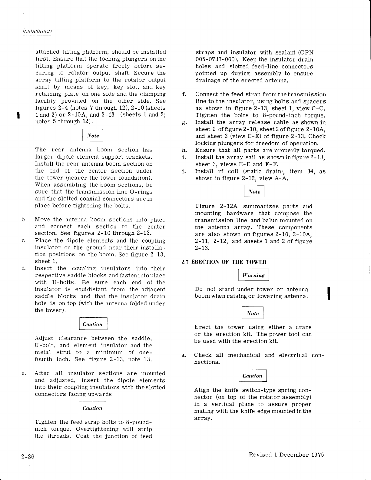
installatlon
attached tilting
platform.
first. Ensure that the
tilting
curing
array tilting
shaft by means of key. key
retaining
facility
figures 2-4
1 and
notes
platform
to roiator
platform
plate
provided
(notes
2-10A,
2) or
5
through
operate freely before
output shaft,
one
on
on
7 through
and
12).
The rear antenna
larger dipole
Install the rear
the
end of the
the tower
When
assembling the
sure that the
b.
and the
place
Move the
slotted
before tightening
and connect each
section.
C.
P1ace the dipole
i.nsulator on the
positions
tion
sheet 1.
d.
Insert the
respective
with
U-bolts. Be sure each
insulator is
saddle blocks and that the
hole is on top
the
tower).
element support brackets.
antenna boom
center secti.on under
(nearer
antenna boom
See
the tower
transmission
coaxial connectors are in
figures
elements and the
ground
on the boom.
coupling insulators
saddle blocks
equidistant
(with
should be installed
locking
piungers
Secure
to the rotator output
slot, and key
side and the
clarnping
the other side.
l2),2-L0
2-13
(sheets
boom sectior-r has
section on
foundation).
boom sections, be
iine O-rings
the
bolts.
secti.ons into
section
2-10 through 2-13.
to
the
near their
figure 2-13.
See
coupling
installa-
into
andfastenintoplace
end
from the adjacent
insulator drain
the
antenna folded under
onthe
se-
See
(sheets
1
and
place
center
their
of the
the
straps and insulator
005-073?-000). Keep
holes and
pointed
drainage
f. Connect the
Iine
to the insulator,
slotted feed-line
up
during assembly to
of the
feed strap fromthetransmission
as shown in figure 2-13,
3;
g.
Tighten
Install
sheet
and
locking
the
2
offigure
sheet
plungers
the
3
h. Ensure that
Install
i.
sheet
j.
Install
shown in figure 2-12,
Figure
the
array sail as showninfigure2-13,
3, views E-E
rf coil
2-l2A
bolts to
array release
(view
all
mounting hardware
transmission line
the antenna
are a-lso
2-ll, 2-12,
2-13.
27 ERECTION
Do
not
boom
when raising
array.
shown on figures 2-10, 2-10A,
and sheets
OF THE TOWER
under
stand
with
sea-lant
the insulator
erected antenna.
using
bolts and spacers
sheet
8-pound-inch
cable as shown in
2-
10,
E-E)
for
freedom of operation.
parts
and
(static
summarizes
and balun mounted
These
2
sheet
offigure
figure 2-13. Check
of
properly
are
F-F.
drain),
A-A.
view
that
compose
components
1
and 2
tower or
or
lowering
(CPN
drain
connectors
ensure
1,
view C-C.
torque.
2-10A,
torqued.
item 34,
parts
antenna.
and
the
on
of figure
a:rtenna
as
Adjust
clearance between the
U-bolt. and element
metal
strut
fourth inch.
e.
After all insulator
and
adjusted, insert the dipoie
into their
connectors facing upwards.
Tighten
inch torque.
the threads.
2-26
to
See
coupling insulators with
the feed
Overtightening wiII
Coat
saddle,
insulator
a minimum
figure 2-13,
and
of one-
note
sections are mounted
strap bolts to
junction
the
8-pound-
of feed
the
13.
elements
the
slotted
strip
Erect
the tower using
or the erection kit. The
be used
Check
nections.
Align the
nector
in
a vertical
mating
atray.
the
with
mechanical.
all
knife
(on
top
the
with
erection kit.
switch-type spring con-
the
of
plane
knife
rotator assembly)
to assure
edge
Revised 1
either a crane
power
and
tool can
electrical con-
proper
mounted inthe
December
1975
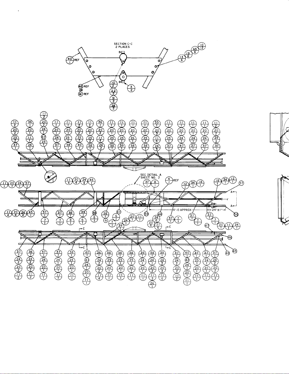
/fj\
x
x
!z
/ s8\
v
sEcTroN c-c
PLACES
2
SEE DETAIL A
,zSrEeiruo. z
./. aA

SECIION
2 PLACES
VIEW A.A
B-B
PART
COLLINS
N0.
QTY
ITEM
PART NAME PART
N0.
764-9034-00 r 2 2 WASHER
r
0
3-0994-000
r
0
3-0999-000
r3-
0
30r-020
305-r25t-OO0
253-000
305
4 3
2 CLAMP HosE 3-rlr6-4
I MITER
2 6
6
CLAMP
5
RIVET
7
RIVET 3/8X t-t/8
305 254-000 3 I RIVET
305- r 255-000
|
3
0-0050-000
0-0052-000 80
9-3254-000 2
3 0-02 88-000
3 0-0290-000 4 t4 WASHER
3 0-0486-000
3 0-0487-000 4 t6 WAS HER
3 3-0033-000 4 t7
333-0379-000
r
3
3-0082-000
3 I 3-0235-000 70
326-226 r -000
326-0932-000 4
326-2293-OAO
r
326-23
6 000 5l 24
326-23 r 8-000
326-232 9-000 2
326-2367-000 2 27
32 6-2369-000
326-2370-000 4 29
326-2446-000
333-042
8- 000 4
333-0442-000
334-0279-000 t2
343-0 r 90-000 2 34
548-3269-002 2
I
9 R IVET 3/8 x t-3/8
28 r0 WASHER
il WASHER
t2
20
t6 I
2
t2
I 2t
4
t7
8 28
2 30
2 32 NUT
CLAMP
HER
WAS
5
WASHER
NUT HEX
I
NUT SELF LKG 8-32
t9 NUT
20 NUT HEX
SCREW
22 SCREW l/4-20x t-t/4
23 SCREW
SCREW 3/8- t6 X r
SCREW 3/8-l6X t-t/4
26 SCREw
SCREW l/2-t3x
SCREW
SCREW t/2-t3x
SCREW 3/4-tAX2-3/4
3l NUT LF-LKG I /4-20
33 NUT tlEX t/2-13
SCREW
35 BRACK ET
549-0783-002 4 36 BRACKET
549-0926-002 2A
549-092 8-002 4
t -aoz
549-266
549-2 708-003
549-2798-O04
549-2799-044
549-2 84
0- 005 43
549-288 t -002
549-2882-OO2
549-9304-004
0r3-r209-030
549-9338-002
764-8065-00 r
764-8066-00
764-8067-00
764-8068-00
764-80?0-00
r
764-8072-AO3 I
764-8074-00 r I
37 ANG LE
38 BLOCK
4 39 BRACE
4 40
2 49
2
2
2
I
BRA CK ET LINE,
4t
SUPPORT RF
42 SUPPORT
PR
S
44
SUPPORT
45
SUPPORI ELEM NO.
46 LINE
47 LINE RF
48 LiNE
PLATE
5C ANGLE
5l GUIDE
52 INS
53
GASKET
54 LAT
ANG
55
EA DER
RF
RF xMsN,
CH ASSY
LE
DESCRIPIION
HosE r,
2-9lr6
3/8x7/8
t-t/4
3/8x
FLT-t/4
-
FLAT
3/8
CABLE
LocK - r/4
LocK -
5/t6
Ftaf - t/2
.3/4
FLAT
5/t6-r8
HEX t/4-20
3/8- I 6
|
X
5/8
/4-20
5/t6-t8x
t-3/8
3/8-t6X t-t/2
t-t/4
t/2-t3x
t-t/2
t-3/4
SELF LKG 3/4- I
8-32 X 5/8
ELEM, NO. I I
ELEM, N0.9, IO
LACING
T I
GHTE NI NG
SUPPORT
SUPPORT
LINE NO. I
RF LINE NO.2
SECTION.TOP
ELEM NO. I
I
9, IO
XMSN, LOWER
N0. 2
S HIM
MTG,
COAX
WIRE ROPE
SPECIAL NO, 2
O
NO. 2
I
764-8076-003 I
764-9022-OOt t2
56 S PR EADER
PREADER
57 S
58 ANG
764-9022-OO2 59 ANGLE
764-9023-00 I 60
764-9026-00 I
764-7279-Ot
754-8063-00
O 62 PLAIE M
r
764-8063-002
326-2262-OOO t2 65
326-2368-000
766-2872-OO4 I
200- r I 98-000
NOTES:
I. IN ALL
BOTTOM IS
t.5
BALLOONS TOP FIGURE 15 LIST OI
SPLIT
QUANTITY
FITT ING c
6r BRACKET
63 ANG LE NO
64 ANG LE NO
SCREW
66 SCREW
67
ANG
NCAilNF
68
2. LIQUID STAKE ALL SCREW THREADS
WHEN NO OTHER
BOND
3.
GASKET,
APPLIED TO OUTER DIA, ONLY
LOCKING MEANS
ITEM 53, TO PLATE,
4. ITEM 48 CONSISTS OF:
r
549-9535-003,
r
549-93t0-002,
I 549-9328.003, LINE
5. CONFIGURATION
I!!ANUFACTURED
L|NE
SECTToN,
Lll,lE
SECTT0N,0UTER
SECTION, ASSEMBLY
OF CENTER BOOM
PRIOR
TO I I DECEMBER,
LE
LE
WITH
PROVIDEI
ARE
ITEM 62,
rNtiER N0. 2
ASSEMBLIE]
srl
S
I
I
SEAL
\
N0.
I9?
Revised
Figure 2-L0.
1
August
197?
Boom Assembly,
Center
(Sheet
1
o1

rnst
allatron
ITEM
QTY
2
4
2 4
I 5
2 6
6
I 9
28
80
2
20
4
t6
4
4 l7 NUT
2
PART NAME
N0.
WASHER
2
3 CLAMP
CLAMP
MITER
RIVET
7 R IVET
RIVET
8
RIVET
r0 WASHER
WASHER
ll
I CLAMP
r3 WASHER
WASHER
t4
WASHER FLAT
t5
WASHER
t6
t8 NUT
t9 NUT
70 20
8
4 22 SCREW
4
5l
NUT
2t SCREW
23 SCREW
24 SCREW
t7 25 SCREW
2 26 SCREw
2 27 SCREW
8 28 SCREW
4 29 SCREW
2 30 SCREW
4 3l
2 32
t2 33
2
2
4 36 BRACKET
20 37
4
4
4
NUT
NUT SELF
NUT
34 SCREW
BRACKET
ANG LE
BLOCK
39 BRACE
40 BRACK ET
4t S U PPORT
42 SUPPORT
PR
43 S
44 S UPPORT
45 SUPPORT
2
46 LINE RF
LINE R F
47
48 LINE RF
2
2
2
2 52 INS
I 53 GAS
I
I
PLATE SHIIU
49
50 ANGLE
GUIOE
5l
54 LAT CH
ANG LE
55
EA DER
KE T
PART DESCRIPTION
|
2-9/ t6
HOSE
,
HosE 3-rlr6-4
3/8x7/8
t-t/8
3/8x
l-t/4
3/8X
-3/8
x t
3/8
- t/4
Fl-Ar
.
FLAT
3/8
CABLE
LocK - r /4
-
LocK
5/r6
- t/2
-
FLAT
3/4
HEX 5/r6-r8
SELF LKG 8.32
tlEX I
/4-20
r
HEX 3/8-
|
/4-20
6
X 5/8
t/4-20x t-t/4
5/r6-t8X
3/8- t6 X
3/8-l6X
3/8-t6X
r-3l8
r
l-t/4
t-t/2
t/2-t3x t-t/4
t/2-t3x
t-t/2
t/2-t3x t-3/4
3/4-tax2-3/4
ELF.LKG I /4-20
3/4- I
LKG
HEX t/2-13
x
8-32
5/8
ELEM, NO.
ELEM,
LAC ING
TIGHTENING
SUPPORT
LINE,
RF LINE
RF LINE NO. 2
SECTION-TOP
ELEtVt N0.
ELEM
XIVSN, LOWER
xr\4sN,
MTG,
WIRE ROPE
ASSY
SPECIAL
I I
NO, 9,
SUPPORT
NO. I
il
NO. 9, IO
N0.2
COAX
NO.
O
I
O
NO. 2
764-8075-003
764-8076-003
764-9022-00
1ea-a.,))-ao)
764-9023-00
764-9026-00
764-7 279-Ot
764-8065-00
764-8063-002
,26-226?-OOO
326-2368-000
766-2872-OO4
200- I I 98-000
NOTES:
ALL SPLIT
I. IN
BOTTOM
2. LIQUID
WHEN NO OTHER
BOND GASKET,
3.
APPLIED
ITEM 48
4.
I
549-9335-003,
r
549-9310-002,
I 549-9328-003,
CONFIGURATION
5.
l\,IANUFACTURED
I
I 57
l2 58
I
I 59
I 60 FITT
I
I 6r
I
I 62
0
I 63
I
I 64
t2
2 66
I 67 ANG
-5
BALLOONS
IS
QUAIiITITY
ALL
STAKE
LOCKING
ITEM
TO OUTER OIA,
CONSISTS
OF CENTER
SPREADER
56
SPR EADER
ANG LE
ANGLE
ING
BRACKET
PLATE
ANG LE N0.
LE
ANG
65 SCREW
SCREW
LE
68 CHANNEL
TOP FIGURE
THREADS
SCREW
MEANS ARE
TO PLATE,
55,
ONLY
OF:
LINE SECTI0N,
LINE SECTIoN,0UTER
LINE SECTION,
BOOM ASSEMBLIES
PRI0R T0
I I DECEMBER,
SIDE,
stDE,
LACING
PECIAL
S
c0Ax
SPACING
MTG,
N0.2
|
/4-20
t/2-t3x
RUBBER
LIST OF
IS
WITH SEALANT,
PROVIDED
WITH
ITEM 62,
NO. 2
lllNER
N0.2
ASSEMBLY
1970
NO.2
r{0. I
ANTENI{A
I
X 3/4
t-3/8
MAIERIAL
CPiI
ADHESIVE,
AND
ITEM
OO5-0547-OOO,
OO5-9042-OOO
Br04 672 6
Figure
Revised 1 August
?-LO.
1977
Boom
Assembly,
Center
(Sheet 1 of
2).
2-27
/2-28

UF
FU
OU
zaz
6O
zo
cl
oO
ox
zdi
r+
o@
IF
rnstallation
o
e
d
U
o-
<o
ao
i-
FF
o
GO
go
ot
f@
ON
oz
oc
co
o
oQ
;
5H
F
+o
o
z
qD
U
U
,;
eZ
B3
Ir1
;I
Se
2?
-N
tQ
9H
oc
f@
OF
Zz
oo
o9
@@
L
oe";
oii<
E>L
33gQ
dUF=62
=
o-'io?e=ts
EfuS
6
o ,,,
H=E=
dFzF
F
Hol
.r
-l
-i3
*6D*
-z
lYa6
El
alts
",'
Figure
2-10. Boom Assembly,
Center
(Sheet
2
ot2),
?i=5
3H.i
FQd>
6U
=
oo=o
-?aE
z-oF
E85o
6
".'1
E+=F
5H33
r"ER=
;-iH
;Fo-
,eOt
oqN=
o&?=
o=nz
@o+u
^'-
u==o
=
..=Y5F
U.
F-
o
z
z\
NF
o
-
N
Revised 15 July 1971
2-29

lnstallatt'on
Pull
b.
up the tower
erecting kit mast
Simultaneously,
one
with
(figures
man
array from under the tower. See
Use
care
array
or
When
C.
perpendicular
interference, it
The
array tilting
prevent
to
theboom,
sail from draggingalongtheground.
the
array can be moved into
to the tower
shouldbe
platform
perpendicular position
spring-actuated lockpins. These
retracted by
(at
bottom of
pins
retracted
position
the array into
Visually
Use
the
d.
position.
tension is equal.
guy
does
erect.
guy
lower
to its
anchor
lower
pulling
the
and then
check
winch to
Check
not become
When the tower is
cable,
termination. Adjust tension on
guy
to 1500
the lockpin release cable
array,
while
release the
position.
fu1l engagement of
pull
side
Ensure that the lower rear
taut before the tower is
winch
on the
Bolt the unhinged leg
position.
winch
Transfer
the
to
2-3, sheet 1,
the
of
upper
anchor
guys
the upper
termi.nation.
2-14.
and
to2600pounds,
For future antenna
ienced
placard,
to theunhingedtower leg. See
e.
Check
personnel
which
the installation
tower is vertical and
properly,
tions
f.
Safety-wire
g.
details
Grout
figure
A and B
space
2-1.
may use
should
turnbuckles as
all
in
figure
under brackets, items
the
winch facility and
2-14
and
2-15).
will wa-lk out
figure 2-16.
elements, and/
position
a
without
locked
ground
intoposition.
is kept in
to the tower by two
pins
can be
cable,
figure
Keepthe
locking
2-17.
pins.
under saii).
moving
the array into
See
the tower to an erect
guys
to
ensure
erect,
side of the
pounds,
of the tower into final
Adjust
fasten the
tower,
percent.
+15
guy
from
figures
See
the tension
*15percent,
servicing, exper-
the
check-1ist
be steel-strapped
2-18.
figure
to be sure that the
that the rotator func-
shown
2-1.
12
and
the
that
the
the
in
13,
2.9 T$A-3
a.
b.
ROTATOR
Run
an 18-conductor
facility to the
Wire
into the
leads from the rotator
rotator
COMROL
antenna tower.
LI}{IT
cable from the remote
control box
control
panel
as shown
in
figure 2-7.
c.
Calibrate
pointer
the
a
the antenna
calibration details.
ZTO RADIO FREQUENCY
KIT INSTALLATION
Install
in
2-19
CPN 515-8606-001
accordance
to meet the MIL
Perform the
a.
Remove conduit from breaker box
box from
(item
conduit
boss of filter
box to
lower conduit to suit.
b.
Mark face of
four holes,
sink
enclosure
control
rerouting
fne 3/4-inch flexibie
c.
below is required
Collins as
d.
3/4-inch
A
remote
control building and be
wall
Remove
breaker box
before disconnecting
control
the rotator
the
on
position.
with
notes
following:
tower.
1eg of
1) to top
fitting.
tower
of breaker box after removing
Reinstall
assembly and attach breaker
leg at a lower
front
0.203
82" to 0.390
panel (item
panel
with
control cable
part
of
flexible conduit must extendfrom
control
panel
or outside of
power
from
or
panel.
control
azimuth
See
INTERFERENCE
Radio Frequency Kit
and drawings in
I 26-6 requirements.
Attachfilterassembly
panel
inch in diameter
inch in diameter.
2) to back
screws
through
conduit called out
but not
the RFI kit.
to outside
grounded
the wa11.
antenna system at
prior
to breaker
wires
panel
control
section 3 for
conduit
fitting intop
position.
as shown
and
(item
conduit.
furnished
wall
eithertothe
from remote
so that
parallels
figure
remove
and
Shorten
and
counter
Attach
of remote
3), after
of
remote
box
drill
d.
in
by
j
-
2.8 STOVING OF
procedures
For
antenna,
2-30
refer to section 3,
ANTENNA
to use
in loweringandstowingthe
paragraph
3.5.
e.
In
all split
is material
quantity.
f.
Before assembly
s ealer.
balloons
item
list
coat all
(figure
2-I9), top figure
and bottom
pipe
Revised
figure
threads
15 July
is
with
1971

sEcroN c-c
PLACES
2
SEE OETAIL A
SHEET NO. 2
1_

SECT ION
2 PLACES
VIEW A.A
B.B
PART
COLLITIS
ilo.
764 9034 00r 2 2
0994 000 4 3 CLAMP
0r3
r
3-0999-000 2 4 C LAMP
0
0r3-r30r-020
305-125t-000 6
305- r 253-000 6
305- r 254-000 3
305- r 255-000
r
3
0-0050-000
r
3
0-0052-000
r 39-3254-000 2
r
3
0-0288-000 2a
0- 0290- 000 4
0- 0486- 000 t6 I WASHER FLAT - t/2
r
3
0-0487-000 4
r
3
3-0033-000 4
333-0379-O00
r
3
3-0082-000
333-r450-O30
r -000
326-226
326- 0932-000 4 22
52 6- 2 2 93- 000
326-t99t-OO0 39
326-r993 -
O00
326-r995-OOO
326- 2367-000 2 27
32
6-2369-000 8 28
32 6- 2 37 032 6-
000
24 46-
000 2 30
333- 042 8- 000 4 3r tI
333- 0442-000 2 32
7
334- 02
9- 000
343-0 r
90-000 2
5 4 8-32 6 9- 002 2 35
49-
7 83-
5
0
5 49- 092 6-
5 49- 092
002
002
8- 002
549-266 r -OO2
795-65
r
2-OO I 4
798-004
549-2
549-2 799-OO4
549-2 840-OOs
r
549-288
5 49- 2
-O02
882- 002 2 45
549-9304- 004
0r3-r209-030 I
549-9338-002
764-8065-00
764-8066-00
764-8067-00
764-8068-00
764-8070-00
764- I 07 2-
003
764-8074-00 r
IT
EM
N0.
PART
WAS HER
NAME PARI
QlY
HosE t,2-9,/r6
I
I
28
r4c ll
MITER
RIVET
7
R IVET
I RIVET
9 RIVET
r0 WAS HER
WASHER
2
I
C LAMP CABLE
r3
WA5 HE R
t4
WASHER LocK
5
r6
WAS HER
t7
filUT HEX 5/r6-r8
r8
NUT LF LKG 8-32
HoSE 3-l/16-4
3i8X7/8
3/8X
3/8
FLAI
FLAT
LocK
FLAT - 3,/4
t2 t9 NUT HEX t/4-20
7A 2a I{U T
2l
I
4
21 25 SCREW 3/8
I 26
4 29
t2
4
2a 37 ANGLE
4
4
I
I
I
2 49 PLATE
2 50 ANG
2 5l
2
I
I
I
SCREW
EW I
SCR
23 SCREw
24
SCR EW 3/8
SCREW
SCREW
SCR EW
SCR EW
SCREW
UT
tt
UT SELF LKG 3/4
33 NUT HEX l/2-r3
SCREW
BRACKET ELEM,
56 BRACK
38 B LOCK TIGHTEIiING
39 BRACE SUPPORT
BRA CK
4t SUPPORT RF LtilE tio. r
42
SUPPOR I
43
PR
S
44
46 LIIiE
48 LINE
52 rts
53
54
55 ANG L SPECIAL NO. 2
EA
SUPPORT
SUPPORI ELEM
RF XMSN, LOWER NO. 2
LINE
R
R F xMSil,
LE
GUIDE WIRE ROPE
GASKET
LATCH A
SELF
,4-24
t
t4-20
5/16-l8X
3/8-?4Xt-t/2
t/2-t3x t-tt4
l/2-t3X l-l/2
t
i2-
3/4-
SELF.LKG I /4-2O
8-32 X 5/8
T ELEM, tio. 9,
E
LAC ING
LINE,
EI
RF Ltt{E ilo. 2
SECTION.TOP
OER
ELEM NO.
F
SHIM
MTG,
SSY
DESCRIPIION
r-r/4
r -3l8
X
-
r/4
.
3/8
- |
/4
-
5/16
LKG 3/8_24
X
5/8
X I t/4
l-3/8
24X1
-
?4Xt-
-
t3
t -3/4
x
ta x 2-3/4
ItO. I I
SUPPORT
I I
t{0.
9,
N0.
2
COAX
t/4
r0
764-
8 07 5- 003 56 S
764-8076-005
764-9022-OO t
764-9022-OA2
764-9025-00
764-9026-00
|
|
764-7279-Ot A 62 PLATE
764-8063-00 r
764-8063-
002 64
326-2262-OOa 65 SCREW
l2 6- 2 368- 000 66 SCREW
PREADER stoE,
PR
57 S
EAOER sroE,
58 At.G LE
ANGLE S PE CI'
59
60 FITT ING c0Ax
6r
BRACKET
63 ATIGLE
ATIGLE tio. 2
sPACti
MTG,
N0. I
|
/4-2(
l/2-l
766-2872-OO4 67 AI{GLE
r98-ooo 5 68 CHAN N
200-l
EL RUBBI
r0
ri0TEs:
I- It{ ALL SPLIT EALLOOIIS TOP FIGURE IS LIST OF
IS
r0
BOTTOM
2. LIQUIO STAKE
WHEN t'O OTHER LOCKING
3. BOTIO GASKET,
APPLIED
4. rTEM
r
r
I
CONFIGURATION OF
5.
MANUFACTUREO SUBSEQUENT
QUAI{TITY
ALL SCREW THREADS WITH SEALANT
ITEM
TO
OUTER DIA. Ot{LY
48 C0NSTSTS OF:
549-9335-003,
|
549-93
0-002
549-9328-003,
MEAI{S
TO PLATE, ITEM 62, WITH
53,
ARE
PROVIDEO
LNE SECilol, INNER
Lrr{E SECTToN, oUTER tio.
,
LINE
SECTIOI'I,
ASSEMBLY
CENTER BOOM
I I DECEMBEF
TO
MA
tao. 2
2
ASSEMBLIE
Figure
Revised
2-10A. Antenna
Installation Details
1 August 1977
Array Center Boom Section and
(Sheet
1
of
2).
Latc

rnstall;i
1)
-/
:\ B.B
-ACES
PART
COLLINS
ilo.
764-9034-00
r
3-0994-000
I 3-0999-000
0
0r3-r301-020
305-I25l-000
I
253-000
305-
I
254-000
305-
I
255-000
305-
r 0-00s0-000
3
r
3
0-0052-000
I
39-3254-000
r
3
0-0288-000
r
3
0-0290-000
r
3
0-0486-000
r
3
0-0487-000
r
3
3-0033-000
9- 000
3- 037
r
3-0082-000
3
33-r450-030
r -000
326-226
326- 0932-000
000
6- 2 2 93-
32
326-r991-OOO
326-r995
-
326-r995-OOO
526-2367-000
6- 2 369-
32
2 37 0- 000
32 6-
46-000
326-24
042 8- 000
333-
333-0442-000
7
9- 000
334- O2
3-O I 90-000
326 9- 002
s 4 8-
83- 002
49- 07
5
6- 002
5 49- 092
549- 092 8- 0C2
I -002
549-266
795-65 r
2-00
2 79 8- 004
5 49-
549-2799-Aa4
549-2840-00s
r -002
549-288
549-2882-002
s49-9304- 004
0r3-r209-030
549-9338-00
764-
8065-
764-8066- 00
764-8067-00
764-8068-00
764-807 0-00
2-
764- 8 07
764-8074-00
I
OO0
000
00
003
QTY
2
4
2
I 5
2
6
3
I
28
143
2
20
4
t6
4
4
2
t2
70
8
4
4
39
?3
8 26
2
8
4 29
2
4 3l
2
t2
2 34
2
4
2a
4
4 39
|
I 44 SUPPORT
2
I 46
I 41
I
2
2
2
?
I
I 54
| I
ITEM
PART
N0.
HE R
WAS
2
LAMP
3
LAMP
M ITER
T
IVE
6
T
!VE
7
IVET
8
RIVEI
9
r0 WASHER
WAS HER
!
CLAMP
t2
r3 WAS
HER
t4 WASHER
WASHER
r5
r6 WASHER
t7 NUT
NUT
r8
r9 NUT
NUT
SCREW
2t
22 SCREW
23 SCREW
SCR EW
24
SCR EW
25
SCREW
SCREW
27
28 SCREW
SCREW
30 SCREW
Ii
UT
NUT
32
ti
UT
3l
SCREW
BRACK
35
BRACK ET
36
AIIG LE
37
BLOCK
38
BRACE
BRA CK ET
40
4l SUPPORT
PPORI
42 S U
PR
S
43
45 SUPPORT
LINE
LINE RF
LINE RF
PLATE
49
ANG LE
50
GUIDE
5l
fts
52
53 GASKET
LAT
ANG LE
NAME
T ELEM,
E
EA OER
RF
CH
PART DESCRIPTION
l6
l, 2-9r
HOSE
3-l,/16-4
HosE
3/8x7/8
l,/8
!-
X
3,/8
X
3/8
-3l8
I
x
3/8
- I/'4
FLAT
FLAT - 3/8
LE
CAB
r
LocK -
/4
-
LOCK
5/16
.
I
FLAT
.
3/4
FLAT
HEX 5/16-18
SELF LKG 8-32
I
HEX
/4-20
3/8.24
LKG
SELF
5/8
t 4-20x
1.,4-20x
s/r6-r8x
3/8
3/8
-
-
t-t/4
l-3l8
?4Xt
?4Xl
3/A-24X1-l/2
t-t/4
t/2-t3X
t/2-t3X
t
/2-t3X
3/4-tOX
SELF-LKG
SELF
HEX
8-32
ELEM,
LAC
T IGHT E
SUPPORT
LINE, SUPPORT
RF LIttE NO.
RF LINE
S ECI
ELEM
ELEM
xMsN,
xMsN,
SHIM
MTG,
WIRE
ASSY
SPECIAL
LKG
t/2
X 5/8
I NG
I ON.T
COAX
ROPE
I
t-3/4
2-3/4
I
3/4.
t3
NO.
N0.9,
TIING
NO.
OP
I I
I{0.
t{0. 9,
LoWER
N0. 2
NO. 2
t/2
/4-20
I I
I
2
l0
I
IO
tiio.
PR EADER
S
I
5
BALLOOXS
QUATITITY
ALL
LOCKING
ITEM
l0-002,
56
SPR
57
At{G
58
AT{GLE
59
FITT It{G
60
BRACKE
6l
P LATE
62
At{G
63
ANGLE
64
SCREW
65
SCREW
66
Atrlc
67
CHAN NEL
68
FIGURE
TOP
THREAOS
SCREW
MEAi{S
PLATE,
TO
53,
OI{LY
DIA.
OF:
sEcTloli,
LltaE
SECTlotl,ourER
LlliE
sEcrlott,
LltaE
CENTER
OF
SUBSEOUENT
EADER
LE
LE
LE
ARE
BOOM
8 07 5-003
764-
764-8076-O05
764-9022-Oa
I
764-9a?2-oo2
27 9-O
I
I
1
0
I
764-9023-00
764-9026-00
7
64-7
754-8063-00
764-8063-002
326-2262-OOO
368- 000
6-2
32
766-2872-OO4
198-OOO
200-r
O
NOTES:
I. IN ALL
2.
3.
4.
SPLIT
IS
BOTTOM
STAKE
LIQUIO
t{O OTHER
WHEN
GASK€T,
BONO
TO OUTER
APPLIED
48 CONSISTS
ITEM
I
549-9535-003,
I
549-93
I 549-9328-003,
CONFIGURATION
5.
MANUFACTUREO
2
Stut,
stDE,lr0.
LACII{G
SPECIAL
c0Ax
PA C II{G
S
MTG,
tt0.
N0.
t
/4-20
|
,'2-
RUBBER
OF
LIST
IS
WITH SEALATIT,
PROVIDED
62,
ITEM
t{0.2
lltNER
tto.2
ASSEMBLY
ASSEMBLIES
II OECEMBER,
TO
At{TEI'ttA
I
2
\ 3/4
t3 X
MATERIAL
ADHESIVE'
WITH
I
-3/8
t
ITEM
OO5-0547-OOO'
CPX
I97O
AND
CPN
OO5-9'i
Figure
Revised
2-10A.
August
L
Antenna
Array
Installation
1977
Center
Details
Boom
(Sheet
Section
1 of-
2\.
and
Latching
Assembll-
2-30A/2

JART
NAI.iE
PARI
/nstalli)tion
OESCRIPIION
-5R
rEr
SIER
a*
?$
itl
ia*
I
E'*
a!!
aA
FW
E,r
C(ET
(
<ET
'.RT
fRr
ADER
CRI
PF
9F
tr
VP
qER
ET
R
R
WIRE
HosE
t,
HOSE
3-
3i8x7/8
r-!
3
8r
3/8X
t-t/4
3/8
X t -3/8
FLAT
.
FLAT
3/8
CABLE
LocK -
LocK
-
5/ t6
FLAT
I /)
-
FLAI
-
3/4
HEX
5/t6-t8
SELF
LKG
HEX
t
/4-2O
SELF
LKG
|
,,4-2a
x
1.,4-2AX
5/t6-l8x
3/8
24\,t
-
3te-zqxt-tri
3/a-
24Xt-t/2
l/2-t3x
t/2-t3X
t/2-t3x
3/4-tox
SELF-LKc
SELF
LKG
HEX
t/2-t3
8-32
X 5/8
ELEM,
iio.
ELEM,
NO.
LACIHG
T
IGlil
E t{ll{G
SUPPORI
RF
LII{E
NO.
RF
LINE
IiO.
s EcT
I 0ri-T0
ELEM
IiO.
ELEM
I{0,
xMsil,
xMSi{,
SHIM
MTG,
9, IO
LoWER
tio.2
COAX
ROPE
2-9l16
t,/
t/4
l/4
8-32
5/8
t-t/4
t-t,,4
t-t/2
t-3/4
2-3/4
t/4-20
3/4. I
I I
9, IO
2
P
II
t6-4
8
3/8-24
t-3il8
I
ilo.
/64-8075-003
764-8076-003
76+9022-OO2
764-9023-00
764-9026-00
764-7
?79-a
764-8063-00
764-8063-002
262-OOO
32
6-
2 368-
i
98 -
0oo
oo
766-2812-OO4
200-t
t
o
I
56
PR
S
I
51
t2
58
I
I
I
o
I
59
60
6t
62
63
64
t2
65
2
66
I
67
1.5
68
PR
S
AT{G
A tIG
FITT
BRACKET
PLATE
AIiG
LE
AiIGLE
SCREW
SCREW
AI{G
LE
CHAN
EADER
EA
LE
LE
IiIG
N
OER
EL
srDE,
srDE.I0.
LAC
IiiG
SPECIAL
c0Ax
PACIIIG
S
MTG,
Ai/IENI{A
[0.
I
rio.
2
|
/4-20 x
Ii2-t3x
RUBBE
ilo. 2
I
3/4
I-3/8
R
t
O
2
ti0TEs:
I.
II{
ALL
BOIIOM
2.
LIQUIO
WHEI{
3. BOI{D
APPLIED
tTEM
r
549-9335-003,
|
549-93
|
549-9328-003,
CONFIGURATION
IYIANUFACTURED
SPLIT
IS
STAKE
NO
OTHER
GASKEI,
TO
48
Cot{stsIs
t0-002,
BALLOOIiS
QUAI{TITY
ALL
LOCKING
IIEM
OUTER
OF
SUBSEQUENT
SCREW
53,
OIA.
oF:
Ut{E
LtriE
LnE
CENTER
IOP
FIGURE
THREADS
MEAiIS
TO
PLATE,
OI{LY
SECnOT{,
sEcflor{,
SECTtOil,
IS
LIST
WITH
ARE PROVIOEO
ITEM
triltER
ouTER
ASSEMBLy
BOOM
ASSEMELIES
To
II
oECEMBER,
OF
SEALAI{T,
62,
WITH
[0.
2
t{0.
2
MATERIAL
CPN
AOHESIVE,
I97o
ITEM
AND
0O5.O547-OOO,
CPN
OO5.9O42
ooo
ASSY
SPECIAL
l-10A"
August
I{O
Antenna
Array
Installation
197?
Center
Details
Boom
(Sheet
Section
I
ot
2).
and
Latching
Assembly,
2-30A/2-B0B

,to,
-3771
I
o_\
cr
,. lZ
B
=
s
irtr)'r
,'g'ALrl*
1:bb,,c(b
G
t6't*
; i
3
''#{1
'l'tuk,l,
(J
il
i
I
I
(l
=
=
)vt'w'
bL.(,')
-
''
.l
t,,
=
t,llt.\
,,,1
c,
Zcl
,
=
'*J-r;Elrp=32,,f[':3''l'
r()=3J")lc,{{'---dr.;
,i
7il1
--
k-
n-1 i
/
!
7
J{,
t-
,{L5-
=
l
Q,
A
t-
Wt'""^:-
-*;-*
I
:
j
-.=---*---<-
'T
i
'
{
I
t/
,
//"9
t
i
!
:(
i
I
)(,/
{f
'7^'
1l

t'
.J
Ltlj,A'
'*;
23
c)
ry
s't)/'lr5
/ .,>
).,t
,^) ,,il
')
wlr)
Lt
,r-+3
%
I
's'&d,t-1
Lol
\t
13
,27
lL,"
9'i
t
5o
=
tj
I
l1--I
:G.,7:*r,'
t/
,
Pe
L \f'^l&L-u'-Al
n
I
\-l
r\-: t
-*--!t=*
"\
t\
i:
'rl
I
//'K
*
t
-r/
i
I
l(
i
I
)(,/
rf
7*
7c,'
1
*---
)
)
i
I /^
lv,
t
,n<
l4
;;;
..)
0,
L
rl
,l
r/
l. i x.
*-
ri
';ri
\.\,
-'J
r-tr
sr-r
uv
'
I
lraa
.h
'\
,\-
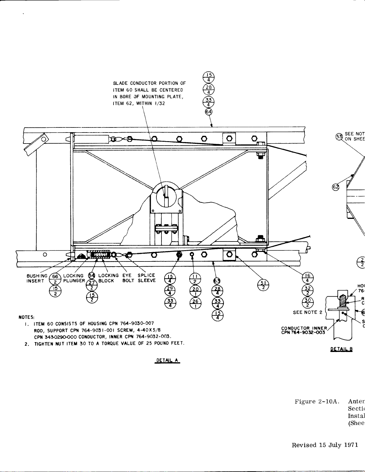
ELADE CONDUCTOR
6O SHALL BE
ITEM
IN BORE CF
tTEM
MOUI|ITING PLATE,
62, WITH|N l,/52
\
PORTION
CENTERED
OF
NOT
SEE
ON SHEE
BUSHING
INSERT
I{OTES:
t. |TEM 60 Col{slsTs
suPPoRT
R0D,
3430290{00
cPil
2. TIGHTEI{
I{UT
LOCKING
PLUNGER
CPt{
cottDucToR,
ITEM 30
Houslttc
0F
764-903
TO A
LOCKING
BLOCX
l-00 I sCREW,4'4OX5/8
TORqUE VALUE OF
EYE SPLICE
BOLT
764-905G007
cPt{
lil,{ER cPf{
SLEEVE
764-9032-OO3'
25
FEET.
POUI{D
.gEJd'IA
NOTE 2
SEE
CONOUCTOR
?6/t-9032-OO3
cPN
Figure
INNER
2-10A.
a
\3
!r.IA!Le
Anten
Secti<
Instal
(Shee
Revised
15
July
1971

lnstallatrcn
BLADE CONDUCTOR PORTION
ITEM 6O SHALL
IN BORE OF MOUNTING
tTEM 52, WtTHtN
BE CENTERED
PLATE,
t/,32
OF
o
SEE NOTE 3
ON
SHEET I
EYE
SPLICE
BOLT
SLEEVE
764-9030-007
cPt{
0t scREw, 4-44x5/8
It{ilER
QUE
764-9032-003.
cPr{
VALUE OF 25
POIJT{D FEET,
.EEICIA
b
NOTE
SEE
COilDUCTOR
?6.1-9032-003
CPil
Figure
Revised
2
INNER
'
eEJAlt-E
2-10A.
15
July
ROO
SUPPORT
764-905t-OOt
cPN
SEE NOTE
scREw.4
cPN
343-0290-OOO
SPACER,
I
-40x5/8
Antenna Array
Section
and
Latching Assembly,
Instailation Details
(Sheet 2 of. 2).
19?1
Center
2-30C/2-30D
Bto4 779
Boom
4


l'l
$_
ViEW
A.A
or
A_J
lnst
allation
COLLINS
PARI
N0.
I
0
3-0994-000
I t2-c00
013-t
-s-!,Q:!91!:9-QQ
3 r
0-0050-000
3 r
0-0052-000
r
3
0-02 84-000 I
3 r
c-0288-000 l8
r
5
3-0082-000
3 l 3-0235-O00
325-O053-000
i26-2262-OAa
2-000
326-23 r
6-
326-23 r
8-000 t9
333-0428-000
548-3267-002
549-0784-002
5 49-0926-
002 t2
549-0927-O02
5 49-
2
09
8-002
5 49- 2655 -002
5 49-265
8-002 2
5 49- 2663-002
s49-2669-002
5494706-OCa-
549-27
08-OC3
549-2798-a04
5 49-2
837-
I
5 49-2
005 I
B 84-002
549-9306-004
5 49-9339-003
766-2353-003
QTY
I
6
I
I
42
99 7
B6
I 2
8 3
6 4
61
6 7
9
24
3 2t
6 22
I 2
I
I
i
6 2A
3 29
2
I
I
I
iTEM
.:
PART NAI\,4E
N0.
2
SPREADER
3
C
4
SEA L
WASHER
5
6 WASHER
WAS HER
B WASHER
9 WASHER
t0
NUT
I
NUT
SCREW to-32
SCREW
SCR
5
SCREW
6
SCREW
NUT
I
BRACKET
9
BRACE
2a
ANGLE
ANGLE
BLOCK
BRACKE
4
BR ACKE T
BR
26
LEAD
aRACKtr
BRAC KE T
SUPPORT
30
S PR
BR ACKE T
LAI\,I P
EW 1.4-24
ACKE
EAD ER
32 SECTION
33
SECTION
34
PR
S
EADER
T
T
-
PART
OESCRIPTION
HOS
E
END,
COAX
FLAT
NO. IO
.
FLAI
I/4
FLAT -
3,/8
LocK
N0. t0
LocK
- t,,4
HEX
t,'4-24
HEX
3/8- I 6
x 3i4
I
x
3i4
i4-24
t-t/'4
X
3.'B-t6 X r
3tB-16
X l-lt4
SELF-LKG I
ELEM,
SPREADER
LACING
BRACE
TIGHTENING
SPECIAL-ELEM
ELEM NO.8
LEFT
E LEC
nf-gLfnf
SUPPORT,
LINE,
TOP
ELEI,!, NO. I
LINE,
LINE,
SIDE NO.
/4.20
NO. I -7
END
NO.2
flO.2
LINE
RF NO.
LOWER
UPPER
I
NO.3
I
NO.
NO.3
3
NOT
ES;
r.
LTQUTD STAKE ALL
WHEN NO
2.
3. ITEM
OTHER LOCKING MEANS
IN ALL SPLIT BALLOONS TOP
IS
QUANIITY
33 CONSISTS OF:
I
549.9322-002, LINE
r
549-9334-003,
r 549-93 r2-004,
Figure z-LL.
SCREW THREADS
SECTION ADAPTER
LrNE SECTt0N TNNER
LrNE SECIl0N 0UrER
Boom
WtTH SEALANT,
ARE PROVIDED
FIGURE IS IIIATERIAL
Assembly,
N0. 3
N0. 3
CpN 005-0847-000
LIST ITEIVI AND
8lo4
Front.
2-3L/2-32
BOTTOM
676 4
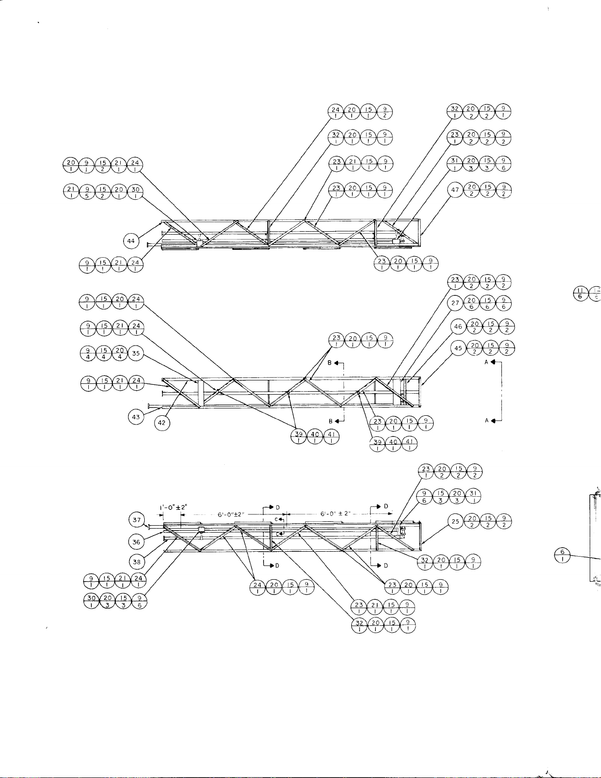
r'-o"a2"
a'-o
xz'
r-l
'l *
@€
Aer
I
I
I
a<l
D

r:nstallation
SECTION
2
SECTION
PLACES
C-C
D.D
COLLINS PART
N0.
or 3-0232-OOO
r 3-0994-000
0
r 3-0999-000
0
0t3-r500-o00
0r3-130t-020
3 I
0-0049-000
3 r 0-00s0-000
3 r
3 r
3
3
3
000
005 2-
0-
0-0284-000
r
0-0288-000
r 0-0290-000
r
3-0033-000
3 I 3-0082-000
3 I 3-0235-000
325- 00s3-000
326-2262-O00
-
6- 093 2
32
000
326-2293-OO0
r
6-000
326-23
r
B-000
326-23
333- 042 B-
000
549-4784-aoz
49- 092 6-
5
549-O927-Oa2
549-092
5 49-
549-2652-OO2
O02
B-002
2 63 8- 002
s49-2654-402
549-2657
s49- 2 69 B-
54
549-2
549-2 87
5
-OO2
003
9- 2 708- 003
800-004
I
-003
49- 2 88 0- 002
549-9302-O04
0t3-r209-020
7-
49- 933
5
I
39-3254-000
002
333-0379- 000
343-0t90-000
766-
35 9- 003
2
766-
766-2357
2 35 B-
003
-aO
764-8078-00
764-8079-00
r-00r
766-24r
r I 96-O00
200-
ITEIU
NO,
20
2l
22
23
24
25
26
21
28
29
30
3t
32
33
34
35
36
39
40
4l
42
44
45
46
47
48
to
ll
t2
t3
l4
l5
r6
t7
r8
t9
2
3
4
5
6
7
B
9
PART
KE T
GAS
C LAMP
CLAMP
CONTACT
I\,1 IT ER
WASHER
WASHER
WASHER
WASHER
WASHER
WASHER
NUT
NUT
NUT
SCR EW
SCREW
SCREW
SCREW
SCR EW
SCREW
NUT
BRACE
LE
ANG
ANGLT
BLOCK
SUPPORT
TUBINC
LINE
BRACKET
BRACK E
CK ET
BRA
SUPPORT
L
c0r
SUPPORT
LINE
LINE
LINE
LA I\,1P
C
NUT
SCREW
SPREADER
SPREADER
EADER
SPR
LE
ANG
ANG LE
ANG LE
CHANNEL
QTY
2
4
3
2
2
I
2a
70
I
t2
B
t2
59
I
t2
4
B
5t
B
4
t2
9
I
4
I
I
I
2
2
4
2
I
I
I
I
I
3
3
3
I
I
I
t
I
r
|
I
I
NAME
T
PART DESCRIPTION
HOSE
HOSE
ELEC
I
FLAT.NO,
O
FLAT. I /4
F LAT -3lB
L0cK-NO. I 0
t
L0cK-
4
/
I 6
L0cK-5/
HEX
5/'16-lB
HEX I 4-20
I
HEX 3/B-
6
to-32 x 3'4
X 3,/4
|
/4-24
l6
X
NO.
REAR
N0. t2
NO,
FREQ
N0.
LOIVER
t-t/4
r-3
I
t-1,',4
I,4.20
I3
ALLOY
I3
LINE
NO.3
t2
NO.
NO.
8-32
t,4-2OX
5/r6-rBX
3,',8-
3,',8-l6X
SELF-LKG
SPREADER
LACI N G
BRACE END
TIGHTENING
ELEM
COPPER
XIVISN
ELEt,4
ELEII
SUPPORT
RF LINE
RADIO
ELEI,4
XI\1SN
XIlISN UPPER
CABLE
SELF.LKG
a-32 X 5 iB
REAR NO, 2
REAR NO.
REAR
BOTTON4
]\,1TG SAIL
BEVELED
RUBBER
I
TOP
REAR
B
VIEW A-A
SECT
ION B.B
NOTES:
I. IN ALL
IS
2. LIQUID
WHEN
COIL,IIEM
3.
INDICATED
ITEI\I
4.
Figure
Revised
QUANTITY
STAKE
NO OTHER
34
ALL SCREW
LOCKING
CONNECTED
BALLOONS
SPLIT
3t C0NS|STS 0F:
r LINE 5ECTl0N, INNER
I LtNE
SECTt0N,
0UTER N0 I
2-72.
15
JuIy
1971
TOP FIGURE
THREAOS
I\,1EANS ARE
I\,4ITER, ITEI"1
TO
N0 I
549-9336-OC3
549-9,308-0C4
Boom
IS i\,IATERIAL LIST ITEM
WITH
PROVIDED
SEALANT,
CPN O05-0547-OOO,
FLANGE BOLT
6,
Assembly,
AND BOTTO[i
BEHIND
8ro4 65s
Rear.
2-33/2-34
POINT
4

lnstallatlon
tTtsrs]14
FRONT BOOM ASSEMBLY
B
-f-------lr+r
r--'-i\E
fF
u)
I
SET
CENTER BOOM ASSEMBLY
I
,. t?
, Lo"
I
lc
rsEr
:l:
REAR BOOM ASSEMBLY
[l-o
I t
-\-
\6
ITE I\,1
2
B
B
B
3
c
c
c
c
4
5
6
7
8
9
D
D
D
D
t0
il
t2
E
PART
COLLINS
QlY
I
764-9023-00 I
I
3
4
326-226 I -OOO
4
0 t3-
I
3 t0-0290-000
4
3 r 3-0033-000
4
326-2
4
013-r209-030
I
0 t3-0232-000
I
3
4
3 t3-0033-000
4
326-2293-OOO
4
013-r500-000
I
0 t3- I 209-020
I
0t3-t30t-020
I
0t3-t500-000
I
549-2652-O02
I
549-2654-O02
I
0
2
3
8
3 t3-0033-000
8
26-2 293-000
3
8
ot3-t500-000
I
0 t3- t30
I
49-9337
5
I
0 t3-0232-000
I
N UIV]BE R
I 0-02
88-000
t-020
t30
2
93-000
r 0-0290-000
t3-0232-000
t0-0290-000
r -020
-002
DESCRIPTION
FITIING, COAX
wAsHER, LoCK- l/4
r/4-20x5l8
scREw
rflTER 90'
WASHER,
LOCK-5/I6
NUT, HEX 5/16-18
5/16- l8X r 3/8
scREW
LINE,
RF
GA SKET
wAsHER, L0CK-5,/t6
NUT, HEX 5/16-t8
scREW 5/t6- t8X I
CONTACT,
LINE,
ELEC
RF
MITER,90'
CONTACI,
TUBING,
ELEC
COPPER ALLOY
LINE, XMSN, REAR
GASKET
wAsHER, LoCK-5/t6
NUT, HEX
scREW 5/16-
CONTACT, ELEC
MITER 90'
LINE,
GASKET
5/16-t8
XMSN,
18X
UPPER
'
3/8
3/8
NO
I NST BOOK
F
ITEM
2-
0
2-
0
0
2-
0
0
0
2-
0
0
2-
3
2-
3
2-
2-
3
2-
3
2-
2
2-
2
2
2-
2-
2
2-
2
2-
2
2-
2
2-
2
2-
2
2-
2
2
2-
3
QTY
COLLINS
N
IVIBE R
U
3
0-0290-000
I
3
I 3-0033-000
32 6- 2 293-000
549-2612-AA2
5 49-9338-002
0 r
5-0232-000
3 I 0-0290-000
3 I 3-0033-000
32 6- 2 293-000
549-267 t-OA2
s49-9339-003
0t3-t I t2-000
5 49-2 669-00
3 I 0-0049-000
3
I 0-0284-000
32
5-0053-000
sqg-groe-oo+
0 l3-0706-000
549-9304-004
0 I 3-0706-000
549-9302-004
549-2 87 I
3 I 0-0049-000
3 I 0-0284-000
32 5-0053-000
-003
DESCRIPTION
WASHER,
NUT HEX 5/r6- t8
scREw
LoCK-5/r6
5,/16-
IBX I 3/B
BULLET, CONNECTOR NO 3
LINE, X[/lSN,
GA SKE T
WASHER, LOCK 5/I6
NUT, HEX
scREW
5/16. IB
5,/t6-
UPPER NO
r8X
BULLET, CONNECTOR
LINE, XI\,,ISN, UPPER NO
END SEAL, COAX
2
LEAD, ELEC
WASHER,
WASHER,
FLAT NO IO
LOCK NO IO
scREW to-32x3/4
LINE, XMSN,
COU PLI N G
LINE, XMSN
COU P LI NG
LINE, XMSN
LO,ryER NO 3
LOWER
LOWER
COIL, RF
WASHER,
WASHER,
scREw
FLAT
LOCK NO IO
ro-32
x3l4
NO
I
IO
tT E tvl
60
t3
2t
5
t4
l7
23
47
I
7
9
E
E
E
t3
l4
F
F
F
F
l5
t6
t7
3
37
5
5
28
29
2
t2
t3
l9
5
6
38
I
t8
G
G
G
l9
20
2t
23
24
H
H
H
3/B
NO 2
NO I
NO
2
2
3
I NSI BOOK
FIG IT EM
t3
2-
2- t3
2-lo
2-13
2-t3
2- t3
2-t3
2-13
2-t
I
2-t
I
2-t
I
2-t
I
2-t I
2-t t
2-t
I
2-13
2-r0
2-t3
2-
t2
2-t2
l-lz
2-12
2-12
Bro4
7
9
t3
24
48
I
7
9
l3
23
33
4
26
8
t2
5Z
2
46
2
36
34
7
t0
t6
78r 4
PART
Revised 15 JuIy
Figure 2-124. Antenna Array,
1 971
Transmission
and BaIun Components.
2-34A/2-348

vrEwc-c
\
F+r
SEE
SHEET
INSTALL
3
DETAIL
INSTALL
UIIDER
SEE
DRAIN
NOTE
HOLE
D
SPACERS,
FEED
4
AS
STRAP
SHOWN,
ITEI\,4S
AS
SHOWN,
TYP
I6
I3
OR
t7
:
26
PLACES
PLACES
REF
oRe
0Re
/a
l
SEE
rH
Ln
SI{EET
Gq
.J
jtEE
3
SHEET 3

vtEwc-c
c
F
--l
SEE SHEET
INSTALL
DETAIL
INSTALL
UNDER
SEE
DRAIN
FEED
NOTE 4
HOLE
D
SPACERS,
STRAP
AS SHOWN,
ITEI/1S I6
AS SHOWN,
TYP I3
OR
26 PLACES,
REF
PLACES
rH
LH
SEE SHEET 3
G+
.J
jsEE SHEET 3

t
nstailation
.
QII
IIEV
NO.
3
2
I
29
t4
22
t2
22
2
3r
to
4
ll--.-
0
lr-t
2
9
20
t4
t2
6
2
2
2
2
2
2
2
2
2
2
2
2
2
2
2
2
t2
I
I
I
I
l
I
I
28
3
I
6
7
2
t8
6
t9
6
2a
4
2t
4
22
I
23
I
24
25
26
27
28
29
30
3l
32
33
34
35
36
31
38
4a
4t
42
43
44
45
4(.
47
4B
49
50
I
52
54
55
56
57
58
59
60
6r
COLLINS
I
2
3
4
5
6
8
9
NUIUBER
0r 3-0232-OOO
r
0
3-0706-000
0.3-
3 I
0-0052-OOO
3 |
0-0284-OOO
s r
o-ozes-ooo
3 r
0-0290-
3 i
0-0292-OOO
I : r
r-oos:-ooo
3 I
3-0235-OOO
i
:zs-ooss-ooo
I
500-ooo
326-2262-Aoa
3
a
4
326-23
324-06
I
I
5
54t-6I23-OO2
54.t-6I67_OO2
548-326s-0a2
54
8-3266548-3268548-327
A-aa2
549-078
549-267
t
549-2672-oo2
scg-zeaz-oo3
549-269
t
5
49-
2
692-
scs-zosl--43
549-2
694_
549
2
695-
549-2696-003
549-
2
69 7-
5 49-2699-003
549-2700-003
543-270t-oo3
543-27
a2-oa3
549-27
03-
543-2704-OO3
543-2705-AA
54)-27a7-oo3
549-2794-oo4
54)-2794-AO4
s+s-z
es
o:ooE
sql-zEs
rlos
5 49-
2
85
2-
3-2
2
285
2
85
85 9-
OO5
85 3-
6- 005
005
r -oos
""-
549-
549-2854-AO5
541
54
549-285
5
s49-
sqg-zeso-oos
s49-286
5 49- 2 R6 2- On5
-..-- ---.
76r-9027-oo
=reors-on-t
761-9029-OO
rcrcoso-ooo-i
i
=i:0418-ooo--i
76A-2 4.,a-
PAR
T
6-OOO
s-ooo
002
OO2
-oo2
-o03
OO3
003
003
003
ao3
e ler,rrrr,
]
i ffi
L
:;'::::'":
I I
BooM
I
eOOtl
;A5HER,rLAT
@
GAS
-COU
WASHER,
wAsHER,
+
SCREW
SLEEVE,
u-aolr,
ffi
u-eoLr,
auLLer,
aLocx,
gLoCr,
BLOCK,
BLOCK,
BLOCK,
B0r
U-BOLT
U.BOLT
SECTION,
@
e lEr,lerur,
ELEMENT,
rrer,re
rur,
tlel,telr.
ELEMENT,
e len,trrur,
ASSEMBLy
aSSt[,teL}
PART
NAME
KE
T
Pt
ll'tG
rUr -
:Zg
LocKlr/4
SPACER
Elel,tTrur
-
eleiva\-lNo.
coNNEaioRlNo.z
sADDLE-_iloJ
saooLe_
SADDLE
SADOLE
SADDLE
NO.
NO.
NO.
-
NO.
-
NO.
-
NO.
3
5
ELEi,'EI\II_==-
lrureruruaIr-ue
ANTEIVM
nrurerrunEwo
alrettra
ANrENrua
arrrrErurrrn
arurerrua
':!i
ClLJED
Ct-UeO
cr_ueo
nrvErio-_
nrlEiEi-ruo-J
r::NN
-
cer,rren....-.-....-.'_.--
-
-
r 4
r,ro ri--_
r r,r,
q--
5
6
7
o-]
ru0.
-
NO.
-
ru6.-r
-
NOlT
--ili'ii
i6J
g-
QTY
ITEM
--.-_No
2,d2
2
2
2
I
66
I
67
24
68
2
69
4
70
4
7t
I
72
I
73
NOTES:
I
I
I,
THIS
I
2.
lN
i.
.
s.
E-E
vtEw
6.
COAT
ASSEI\,IBLIES
Do
ncHrENrNG
7.
IIGHTEN
8.
ON
C L
LUBRICATE
9.
SPRAY
B.RE
ALL
,s
QUANTTTY
LIQUtD
orHER
::1]...lrlRE
HAR,*ARE
MouNr
pAss
F-F
THREADS
Nor
ASSEIUBLY
EA
N
0F
rxE
)
J
.l
]
I
I
I
I
I
I
,.
frrjl
I
l.
,,
I3.
t4.
INSIALL
SEALANT,
x€y
;?iJ
WHEN
ASSEIVIBLIIIG
ADJUST
tNSULAT0R
THE
ANTENNA
R0TAT.R
RETAINER.
0pEN.
HEA'
APPLY
AN
AND
THE
I
O'
l-
t330ffi
63
64
65
005-03
333-If,5t-ooo
326-23-.
343-0
3 I
005-t366-0to
005-t365_0to
FIGURE
APPLIES
SpLtT
sTAKE
LOCKTNG
AREA
wtrH
LATcH
cABLE
WITH
ovER
,GHrEr{..::Lrs,
couLD
NUTS
INDICAIED
OF
R OTA
T
OR,'il
WITH
LIGHT
COAT
ANTENNA
LowER
TtLTli!c
ITEM
suppLIED
THE
ELEMENTs
Do
Nor
ARRA'
0urpuT
*EDGE
rHE
AXIAL
FORCE
ANTENNA
COLLINS
PARI
tiutrlgen
r
3
3-0082-OOO
326-226
I
-OOO
005-0547-ooo
005-0737-0oo
I
8-OOO
I
87-OOO
0-007
TO
BALLOONS
ALL
cABLE
OF
TOp
scREw_rHREAos
MEAi{S
ARE
ARour{D
SEALER,
BRAcKET
THRU
ALL
BOLIS,
THREAD
REsuLT
IN
ANTEI
TJ,
IIE|\,ll
67
OF PRIMER,
TTLTTNG
6
rNcHEs
pLATFORM
73,
THROUGH
wtTH
RorAToR
ELEMEI{TS
so
THAT
coME
wrrHrN
,LTTNG
By
'HAFT
THE
sLor
ANTENNA
TILTING
,LTTNG
BETWEEN
PLATFORI\,I
scR
SEAL
#fi"'::T
ANTENNAS
,TEM
ITEMS
LUBRICANT,
rN
TJfJ
pLATFoRr,
oF
AND
'LATF.RM
rHE
FIGURE
PROV|DED
ENDS
oF
66,
(pARr
cLAMps
I2
fil':T,
sERrous
VIE.W
G.G
YJ'I,
ITEM
RorAroR
ROTATE
KEY
SLOT
wtrH
ONIO
BOOM
rHE
r,/4
FoLLowr*a,
rN
THE
ANTENNA
pLArFoR,
,,.
IuANUFACTURED
,r
ustNG
FEED
,'
,*iar,
oF
AN,
ANO
ITEM'67'"'
ooroi.
'O
i:
72,
oaao*
orrrrr-r-rir
THE
sEALANT,
,oooia.
,rc,
,o,
O*"A'O
BORE.
PART
ttIAME
LocK
-
N0.
,ra,
*rr-r-a,
SEALANT,
srRAps
*i
;i;;
;r);
r*ra*
o,oroaa,
15,
IHAT
vrEw
cc,
ii,i.^or.
O.
,,.
'U
JiIT
J
ON
ROTATOR
io
o*r.
SHAFT
BRACKETS,
r_roar,
o,
,*a
,iroL
,a
*ir-ora,
*iroui'rra
,lir,*i
,*a'io
*O,O'O*
I
PRIOR
ono
trEM
AND
DETAIL
rrEM
ARE
"
FrcuRE
K'J}
OUTPUT
wrrH
ADDTNG
trEM
73,
IAKE
o*o
srRur
,.orroa,
450.
0",,,
TP;
IO
SEPT
SEPT
rorror
rTOM
65,WHEN
WHEN
rHEtR
MouNnN
MOUNTING
D
pER
58
PER
or
rro*r,i
sHowtr/
USED
ON
ON
ELEMI
ELEMET{T
2_r3.
3.
-855
i
I3;i,,
IM
iI,;:'
AND
SHAFT
;HAFT
'EALANT,
ADOtilOtiAL
AND
rNsrAL
CARE
TO
aaaraM
sEcao
FRoM
THE
LocKrNG
KEy
,ore
t
50..
,,O"
BrO4
I9
t966
FIGURE
*f
ttlo
ltlO
vrg
VIEW
tN
ovEr
OVER
t -000,
AII
AND
ON
679
(-1j
s.
E@@(
@@c
@@(
@(
/a\
14
\t/
s
G
Figure
2-13.
Installation
of
Antenna
Array
(Sheet
1
of
B).
2-35/2-36

DETAIL
D
INSTALL
SPACERS,
UNDER FEED
SEE NOTE
4
THRU
STRAP
ITEMS
AS
SHOWN,
I6
OR
:
26
PLACES,
REF
VIEWC.C
r,
Lr
SEE SHEET 3
.!,.sEE
B+r
BJ
:l
SEE
F
-J
SHEET
INSTALL
SHEET
3
DRAIN
HOLE
AS
SHOWN,
TYP I3
PLACES
3..

6
0R t7
WN,
26 PLACES,
6-"
I
PLACES
3
2rV8Y68 e Vi zVr z\./r l
2
2
)@@@
@@
YE
/
\:_/
il
t)
2 2
4
rT
rvl
E
QTY
REF
VIEWB-B
2
2
COLLINS PART
NO
NU[IBER
0 r
3-0232-000
|
0
3-0706-000
cr3-r500-000
r
0-0052-000
3
3 r 0-0290-000
i
3
0-0292-000
I
3
r0
r |
t2
r
3 326-a?93-000
r4
3-0033-000
3r3-0235-000
325-0053-000
326-2262-OOa
r6+C0
326-23
t5 324-06r5-000
54r-6123-002
541-6167-AA2
r
8 548-3265-002
r
9 548-3266-002
548-3268-002
2t 548-3270-OO2
22 549-C785-002
23 549-267 t -OO2
549-261?-OO2
25 549-2687-003
27
549-?692-Oa3
_
?8 549-2693-003
29 549-2694-003
30 549-2695-003
32 549-2697-003
33
549-26-c9-003
-2
34 549
35
37
38
39
40
4t
42
43
44
45
46
47
49
50
5l 539-2858-005
52
53 54-o-2360-005
54 549-236 r
55
59
6l
700 -O03
70 r -O03
549-2
549-2 7C3-003
-2
704 -003
549
549-2 705-003
549-2707-003
5a?-2184-OO4
54?-2794-A04
-2
8 50
-00
5
.OO5
I
549
549.285
549-2852-005
549-2853-005
549-2854-005 E
549-2855-005
549-2456-005
5:?-2457
549-2t59-005
5 49-2 3 62
744-9427
764-9028-00
764-9C29-00
3
333
-A05
-005
-C0
-aA
a-cc50-000
-000
-C
42 8
5
t
r
r
766-2409-005
GAS
KE T
CO
UP LI NG
CONTACT,
WASHER
WASHER,
WASHER,
WASHER,
WASHER,
NUT, HEX
NUT, HEX
S CREW
SCREW
-
SCREW
.
SCREW
.
SCREW
SLEEVE, SF
SLEEVE, SF
U-BOLT, EL
U-BOLT, EL
BLOCK, SAC
U.BOLT,
BLOCK, SAD
BULLET,
BULLET,
SECTION, Ei.
BLOCK, SAD
BLOCK,
SAD
BLOCK,
SA'
BLOCK,
SAi
BLOCK, SA]
BLOCK, SAD
BLOCK, SAD
U.BOLT NC
U-BOLI NC
U-BOLT NO
IJ.BOLT NO549-27A2-Oa3
U-BOLT NO
U.BOLT NC
u-BoLT NC
BL0CK,SAD
SECTlo\ :_
SECTt0\,
ELE[.1ENT,
ELEMENT,
E
LEi'ENI
I.,4E
E LE
N T
I\,4E
LE
NT
I\,,tE
E LE
NT ,
ELEti.4ENT.A
ELE\,,rE\r
ELEr\4ENT,A
ELEMENT,
ELEI\,4ENT,
ELEMENT,
ELE[,IENT
BOOiV ASSE"'
B00l\.,1 ASSE','57
BOOfuI
ASSE','
WASHER, F
NUT, HEX
SAtL
'
t'
L:
L:
5
3
3
EL
CC
C:
:_
A
A
,
1
a
A
A
A
A
Revised
Figure
1 August
2--
197i

ITEM
OTY
3
2
I
?9
t4
22 6 3
t2
2?
l2 9 3
3l
t4 i
2a 2 326-226?-OOO
12
29 4
2a
l4 6 54
t? 7
2 B 548
6
6 2a 548-3268-002 BLOCK, SADDLE
4 2t 548-3270-OO2 U.BOLT, ELEMENT
4
I
I
6 25 549
2 26 549-269
2 27 549-2692-003
2 549-2693-003 BLOCK, SADDLE
2 29 549-2694-003 BLOCK, SADDLE
2 30 549
2 3r 549-2
2 32 549-2
2
2
2
2 36 549-2702-OA3 U-BOLT NO. 4
2 37 549-2
2
2 39
2
2 4t 549-2784-OA4 SECIION,
t2 4
I
COLLINS PART
NO
2 0
3
4
5 3
7
8
t0
r9
22 549-O785-OO2
23 549-267
24 549-2672-OO2
NUMBER
I
r
0
3-0232-000 GASKET
r3-0706-000
0r3-r500-000
r 0-0052-000
3
r 0-0284-000 WASHER,
r 0-0288-000 WASHER,
3 I 0-0290-000
r 0-0292-000 WASHER,
3
r
3-0033-000 NUI HEX.-5lr6-r8
r
3
3-0235-000 NUT, HEX.
32 5 -0053 -000
6-4rl93-000 scREW-5/t6-t8Xl3/8
3 32
5 324-06
r6&0 scREW-3/B-t6Xr
326-23
r
r -6 r
23-002 SLEEVE, SPACER
54 t -61
67-OO2
-3
2 65
544-3266-OO2
-2
68 7-003 SECTION, ELEI,llENT
COUPLING
CONTACT, ELECTRICAL
WASHER,
WASHER,
scREW-to-32X3/4
SCREW t/4
5-000 SCREW 3/B-t6Xtt/4
SLEEVE, SPACER
-002
U-BOLT, ELEI'ENT
U.BOLT, ELEfu!ENT - NO. 8,9,
BLOCK, SADDLE
-OO2
t
r -003 BLOCK, SADDLE - NO. I
BULLET,
BULLET,
BLOCK, SADDLE
-003
-2
69 5
BLOCK,
696-003 BLOCK, SAODLE
33 549-2699-003 U-BOLT
69 7-003 BLOCK, SADDLE
54
35 549-270
38
40
700-003
549-2
r
703-003
-O03
U.BOLT
U-BOLT
U.BOLT
549-2704-OO3 U.BOLT
549-2705-OO3
549-2707
-OO3
U-BOLT
BLOCK,
549-2794-OO4 SECTION, ELEIV1ENT - NO. 8.I5
43 549
44 549-285
45
46
-2
850-005 ELEI\.4ENT, ANTENNA
r -005
ELEIUENT, ANTENNA
549-2852-OO5 ELEIVENI,
-2
853
-00
5
ELEI.ltENT, ANTENNA
549
47 549-2854-OO5 ELEI\,IENT, ANTENNA
-00
85
549-2
5
-2
858-005
859
5 ELEMENT, ANTENNA GLUED
ELEiVIENT,
-00
ELE['ENT, ANTENNA
5
ELEMENI, ANTENNA
-005
r
ELEMENT, ANTENNA RIVETED - NO. 6
49
549-2 856-00 5 ELEIUENT, ANTENNA RIVETED
549-2457 -OO5
50 ELEMENT,
549
52 549
-2
53 549-2860-005
54 549-286
PART
FLAT
LOCK
LOCK
LOCK
LOCK
-
3/8
-
CONNECTOR
CONNECTOR
SADDLE
NO. I
NO. 2
NO. 3
NO.
5
NO. 6
NO. 7
SADDLE
ELEIVENT
ANTENNA
ANTENNA
ANTENNA
NA\4E
-
3/8
.
NO.
-
I/4
-
5/I6 24 68 333-t35t-000
.
3/B
-
r6
x
2a
3/4
.
NO. I5
-
NO. 8,9,
-
NO.
-
NO. I I,I2
-
NO.2
-
NO.3
.
NO. 4
.
NO, 5
-
NO. 6
.
NO.
-
NO. I3
GLUED
GLUED
GLUED
GLUED. NO I
GLUED
RIVETED - NO. 2
RIVETED
RIVETED
RIVEIED
549-2862-O05 ELEI\,4ENT, ANTENNA RIVETED. NO.
764-9027
56
764-9028-00
57
764-9029-O0 I
58
28 59
28 60 333-042 8-000 NUT HEX., SELF-LOCKING
I 6l
3 I 0-0050-000
766-2
-04
t BOO[.4 ASSEIUBLY -
r
BOOIU
B0Ol\,,t ASSEI\rBLY - REAR
WASHER, FLAT
-00
409
5 SAI L
ASSEI\,4BLY
-
FRONI
.
CENTER
I/4
IO
.
NO.2
NO. 3
7
IO
I I,I2
-
-
-
-
-
IO
N0. I
NO.9
NO. IO
NO 2
NO
-
NO. I
-
NO. 3
.
NO. 4
.
NO,
t/4
rTEr\,,r
oTY
.
NO NUI\,^BER PART
2 62
2
2
2 65
I 66
I 67 005-03
330-3862-000
63 3 r
64
PART
coLLtNS
3-0082-000
326-226 I
-000
005'0547-000
005-o737-OO0
r
8-000 THREAD
sET SCREW s/16
NUT, HEX.
-
scREW- t/4-20X5/8
SEALANT
SEALANT
(IO
(2
LUBRICANI
NUT, HEX.. SELF
2 69 32 6-2332-000 scREw-3/8-t6X2t/4
NOTES,
I. THIS FIGURE APPLIES TO ANTENNAS
SUBSEQUENT
2, IN ALL SPLIl
AND BOTTOM
LIQUID
3.
ITEM
COAT ENTTRE AREA AROUND ENDS OF FEED SIRAPS
4,
THEIR
TO SEPT.
BALLOONS TOP FIGURE
FIGURE
STAKE
6'WHEN
MOUNlING HARDWARE WITH
I966.
IS
QUANTIIY.
ALL SCREW IHREADS USING SEALANI,
NO OTHER LOCKING MEANS ARE PROVIDED.
IVANUFACTURED
SEALER,
26 PLACES, SEE DETAIL D.
I\,4OUNT LATCH
5.
ITEM 58
AND UNDER
PER
VIEW E-E
4 ANGLES
CABLE
6. COAT THREAOS OF BOLTS,
ON
USED
ELEMENT
ITEM 67-
DO NOT OVER THIGHTEN BOLTS, ITEM 6, VIEW G.G,
FIGURE 2-I3. OVER IIGHTENING COULD RESULI IN
SERIOUS DAMAGE TO ARRAY.
7. TIGHTEN NUTS
BEFORE ASSEI\,lBLY OF
8,
9.
I
CPN 5
5-855
ANTENNA TILTING PLATFORM AND
POSITION
INSTALL THE TILTING
ASSEMBLIES
INDICATED IN VIEW G.G
I.OO I
CLEAN
,
KEY
IN ROTATOR OUTPUT SHAFT
IO. COAT SET SCREWS, ITEM 62,
AND TIGHTEN AGAINST
I I. WHEN ASSEI\,4BLING ELEI\,{ENTS ONTO BOOM BRACKETS,
TO ADJUST THE ELEI\,IENTS 50 THAT THE SADDLE,
CARE
(PART
BRACKET
PASS CABLE
AS
SHOWN
THRU
IN VIEW F.F.
ITEM I2 AND I5, THAT ARE
WITH THREAD LUBRICANT,
CAUTION
ANTENNA ARRAY WITH ROTATOR KIT
ROTATOR SHAFT AND BORE OF
LUBRICATE WITH ITEM 67.
PLATFORM
KEY AFIER
WITH
UNTIL
SEALANT,
ASSEfu!BLY.
U.BOLT, AND ELEMENT INSULATOR DO NOI COME WITHIN
LESS THAN
5
7
20
I/4
INCH OF THE
IVETAL
TRUSS SECTION.
inst
NAME
-
t8
X 3/8
t/4 -
20
CC BTL)
OZ TUBE)
(8
OZ JAR)
L0CKING 3/8
IS ITEM NUMBER
ITEM 66,
ALL CLAMPS
LB. FT
25
KEY
SLOT
ITEM 65,
TO
OF ITEM 57)
TO
IT BOTIOMS OUT.
allation
AND
AND
TAKE
8l04
t6
700 6
I
Revised
Figure
1 August
2-13.
L977
Installation of Antenna Array (Sheet
2 of 3).
2-37
/2-38

ROTATOR KIT
cPN 5r5-8sst
-00t
SEE
NOTES
7
THROUGH
cauTl0N.
DO
NOT
TIGHTEN
2
OVE:
GUY. ANCHOR ANO TOWER
5r5-80t2-00t
cPN
VIEW H-H
ROTATED
ANTENNAS I,,!FG
SUBSEQUENT
SEPT
ANCHOR AND TOWER
GUY,
5r5-80r2-00r
cPN
KIT,
I
966
KIT
90'CCW
TO
ROTATOR
KIT
cPN 5t5-855t
-00r
KEY
PART OF ROTATOR
cPN 5t5-855t -O0t
KIT
VIEW
H-H
ROTATED
ANIENNAS
PRIOR
TO
9O CCW
MFG
SEPI. I966

NOTES
THROUGH
7
CAUTION:
NOT
DO
TIGHIEN
OVER
KIT
TOWER
AND
ANCHOR
GUY,
515-8012-001SEE
12
ROTATOR
KIT
cPN
-l
G.G
VIEW
ROTATED
9O
I
|
I
r---1_A
*----1-
O-..
OR
6)*.,
\,-/
OR
/a:\---
q
/
,HEr-
f
OR
TYPICAL ELEMENT
DETAIL
/al\^--
f?*"
CW
5
NOTE
SEE
56,
lTE[4
OF
PART
,€l/
ae\L
atr-
\3)
PART
OF
ITEI\4
57,
SEE
NOTt
5
Figure
2-L3.
Installation
of

ANCHOR AND
UY,
PN
5t5-80t2-001
TOWER KIT
@*.,
oR-
lnstallatlon
[-----f---1,
G')*.,
OR
@*"
v_ffi:
REF
(ratnEr
di*,.
OR
-1
/
T\PICAL
-l
,
ELEMENT
*-.1
DETAIL
REMOVE
THIS
BRACE,
PART
ITEM
58,
AND
INSTALLING
I
SEE
NOTE
VIEW
E-E
5
REINSTALL
SAIL
ASSEMBLY,
OF
AFTER
ITEM
6I
Figure 2-L3"
Installation of
Anterura Array (Sheet
3
of
B).
Bi04
675
2-3e/2-40
1r
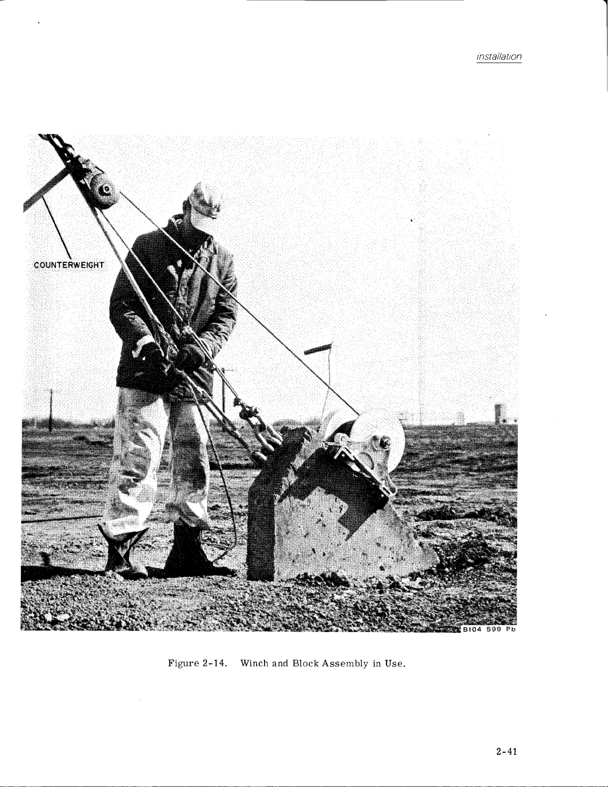
COUNTEfrWEIGHT
lrtstallaton
4
Figure 2-14.
Winch
Block Assembly
and
in Use.
2-41

lnstallailon
qb
2- 42
Figure 2-15. Antenna
Lowered
in
Pc;sitiou With Erecting Mast
lnstalled.
BlO4
597
Pll

: ..-..^;.*,",".,"e"*'"'r,"-
l#ry'
\..
r!..- .a
\.
*)@f*":@
" '"..-?l
;"i4i:t'
, ..;
A
lnstallatt'on
.&
.;
:,,
:$
Md
&.
.
Ji{
i,&
!t.
i l.r
iri
1t i
il;
.jrt'
Figure 2-16.
Antenna During Erection
Array Hinging
With
.i
h
Detail.
2-43

rnstallatlon
2-44
Figure 2-1?.
Antenna
During
Erection
With Array Locked.

COLLINS RADIO COMPANY
A
v
I
DO NOT RAISE
-
2.
CHECK
PULLEY.
3.
CHECK
4- GREASEWINCH AND
PREFORMED
IF
cPN
LOWER:
TO
I. ROTATEARRAY
2. DISCONNECT
3. REDUCE MIDDLE
OBTAIN
4. DISCONNECT
REMOVE
5,
INCREASE TENSION
6.
7. LOWER
MAKE SURE
8.
CHECK
IF THE GUY
I
/2
PROPER TENSION
CROSS.WIND. UP.WIND
C. DO NOT SIAND UNDER
CAUIION
OR
CONDITION
MUST
ALL
ALL ERECTING
GRIP
r
0
5-2354-00.
SO
COAX
FOR
'FEEL"
MIDDLE
2 TOWER
ARRAY USING
CABLE ENTERS
MIDDLE SIDE-CUY
ANCHOR
THE GUYS
INCH
LOWER ANTENNA
OFWINCH,
THAT FRONT
AT BASE OF
SIDE.GUY
BASE NUTS
[/UST
PROCEOURE
ERECTI0N
-
THE FOLLO
CABLE,
BE USED.
BOLTS FOR TIGHTNESS.
KIT
AT ALL FITTINGS.
PULLEY
HAS BEEN
THIS TENSION.
ON WINCH
LOOPS ARE
CAN
REMOVED,
OF BOOM
TOWER.
TENSION
TOWARDSWINCH.
GUY
BELOW
CABLE AND
HAND CRANKOR
GIN-POLE
TENSION
NOT IN LINE
OVER-TIGHTEN
MAINTAINED TO BRACE
ALSO BE
MAY
GUY
WHEN
TOWER
ROTATABLE
FOR
Klr, cPN
WINDS
IN
COUNTERWEIGHT,
TO APPROXIMATELY
SEE NOTE.
LEG EXTENSION.
POWER
SLOT.
CONTINUALLY DURING
DEVELOP
RELEASING ARRAY
LOG
LOWERING
TURN OFF A.C.
OR
5 I s-8s24-O0
4O
ABOVE
NOT RE-APPLY.
DO
LINEWITH TOP GUY
IS IN
REMOVE SHACKLE
TOOLKIT. CPN 5I5.B6OI-OOI.
WITH THE TOWER
A TOWER
CAUSING
LBS. MAX,.A
6OO
ANTENNA
PERIODIC
WITH
RAISING
I
MPH.
PREFOR[,lED
POWER TO ROTATOR.
2OO
GRIP,
NEW
USE
TOWINCH'
LBS. SHAKE GUY
PIN FROM
LOWERING.
OR
RAISING
TOWER
LATCHES,
HINGE
LEG
4O
WITHIN
TO BUCKLE.
AGAINST
N/]PH WIND.
t:nstallatlon
237B-3
.
AND
GRIP
TO
TURNBUCKLE.
A STRONG
RAISE:
TO
WEIGHT OF
ON WINCH CABLE
INCREASE
L
TENSION
ADJUST
2.
RAISE
3.
OR LOOSE.
SWING
4.
SWING
LATCH PLUNGERS
TENSION
LIFTING
IN
MIDDLE SIDE GUY
IVIAKING SURE
TOWER
ARRAY INTO
ARRAY
POSITION.
INTO FINAL
ARE
GUY CABLE
TENSION
POSITION, RELEASE
FULLY ENGAGED
5. RAISE TOWER T0 VERTICAL
RECONNECT
6, TENSION
7.
REPLACE
B. SAFETY.WIRE
RECOMMENDED
CHECK TOWER,
3,'4
I,/2
/8
3
5/I6
I,,4
IO-32BOLTS
NOTE: USE IN.LINE DYNAI,IOMETER OR CLAI\,4P-ON DYNAIVOMETER NO. AT.6896
25[ICABLE-
FOR I/2
TURNBUCKLES
BASE NUTS
TO 26OO
ANO COAX.
TOP GUYS
ALL TURNBUCKLES.
MAINTENANCE:
ROTATOR, AND
LB-FT
DIAMETER
DIAMETER -
DIAI\,IETER
DIAMETER
DIAMETER
GUY,
- 320
90 LB-FT,
.
25 LB.FT
I32 LB-IN
-
LB-IN
- 75
.
BLB-IN
(OBTAINABLEFRO|\,llGRAYBARELECT.CO.).
(OR
A SUITABLE
SUBSTITUTE).
SO THAT
I2,OOO LBS. MAXIMUM
IS
2OO LBS.
TO
I\,'IIDDLE SIDE GUY
PULL LATCH CABLE
TENSIONS DO
LATCH CABLE
IN TILT
P0SlTl0N. PLUMB TOWER
AND RELIEVE TENSION
LBS. MIDDLE GUYS
RE.PRESSURIZE COAX.
THREE MONTH INTERVALS
ARRAY FOR FOLLOWING
(GALV.
BOLIS),
ANTENNA IS ON
AT THIS POINT.
NOT BECOME TOO
TO RETRACT
PLATFORI\,4 EAR.
WITHIN
ON WINCH.
I5OO. RE-CHECK
TORQUE
45 LB-FT
IOMSCALEFOR3,,BGUY,25M
USE
LATCHES AND
AND
CHECK
l12 INCH WITH TRANSIT,
PLUii]B OF TOWER.
VALUES ON BOLTS:
(STAINLESS
TOWER.
TIGHT
THAT BOTH
STEEL BOLIS)
CALIBRATED
FOR
804 674
4
Figure
2-18.
Antenna
Raising
and
Lowering
Checklist
Placard'
2-
45
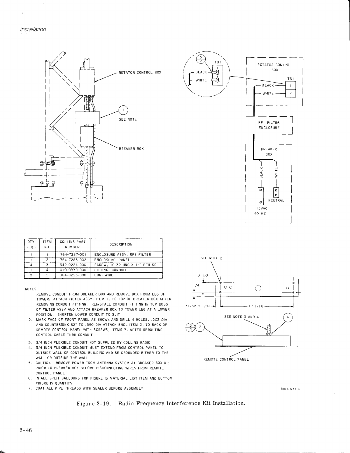
trtstallation
l_---l
tI
r{-1
f1h-
(
I I ,/
I
L--'
RorAroR
coNTRoL
Box
ROIATOR
CONTROL
BOX
-t
I
I
I
_l
SEE NOTE
BREAKER BOX
I
J
1i
-
X-
I
RF I
FILTER
ENCLOSURE
_l
;-;^-_l
i-
I
I
I
I
I
I
L
BOX
OF
<=
J=
m>
tl
tt
r"l rit
l|bl
l^ I NELTTRAL
t9l
r r
5vAc
60 HZ
I
I
I
I
I
I
_l
REQ D
NOT
N0.
I
I
I 2 764-7243-O02
4
I 4 0
2 5 304
E S:
I. REMOVE CONDUIT
TOWER:
REI"4OVING CONDUIT
OF FILTER
POSITION.
I\,4ARK FACE
2.
AND COUNTERSINK 82'TO.39O
REMOTE
CONTROL
3/4 INCH
3
INCH FLEXIBLE CONDUIT MUST EXTEND FROM
4
3/4
OUTSIDE WALL OF CONTROL BUILDING
WALL OR
CAUTION
5.
PRIOR TO BREAKER BOX BEFORE DISCONNECTING
CONTROL PANEL
IN ALL SPLIT BALLOONS
FIGURE IS
7. COAT
ALL
NUI\,,1BER
764-7287 -OO
342-O224-OO0 SCREW, IO-32
r
9-0330-000 FITTING, CONDUIT
-0
ATTACH FILIER
t ENCLOSURE
ENCLOSURE, PANEL
-000
2 53
FROM BREAKER BOX AND REMOVE BOX FROI\,4
LUG,
ASSY, ITEM I, TO TOP OF BREAKER BOX AFTER
FITTING. REINSTALL
ASSY AND ATTACH BREAKER BOX
SHORTEN
CONTROL PANEL
CABLE THRU CONDUIT
FLEXIBLE
OUTSIDE THE WALL
-
REMOVE POWER FROI\,4 ANTENNA SYSTEM AT BREAKER BOX
QUANTITY
PIPE THREADS WITH SEALER BEFORE ASSEMBLY
LOWER CONDUII TO
OF
PANEL A5 SHOWN AND
FRONI
CONDUIT NOT SUPPLIEO BY COLLINS RADIO
DIA ATTACH
WITH SCREWS,
TOP FIGURE IS ]\4ATERIAL LIST
COLLINS PART
ITEM
QTY
Figure 2-19. Radio
DESCRIPIION
ASSY, RFI
WIRE
CONDUIT
TO TOWER LEG
SUIT
DRILL 4
ENCL ITEI\,I 2, TO
ITE]\,lS
AND
BE GROUNDED EITHER TO THE
FILTER
X I/2 PFH SS
UNC
FITTING IN TOP BOSS
HOLES,
AFTER
3,
CONTROL
WIRES FROM REMOTE
ITEM
Frequency Interference
LEG
AT A
,203 DIA,
BACK
REROUTING
PANEL
AND BOTTOI\,1
OF
LOWER
OF
TO
SEE NOTE
2
Tl
til,z)
r
3t/32
SEE
NOTE 3 AND 4
REMOTE
OR
CONTROL PANEL
Kit
Installation.
BtO4
678 6
2-46

seetion
3
3.T GENERAL
Point
the antenna
velocity exceeds
when winds of 143 mph
98 mph
of
ice)
are expected.
(with
Above caution
manufactured
Antennas manufactured after that
equipped
which
237B-3
The
sents a 50-ohm loadatanyfrequencyinthe 6.5- to
40.0-MHz
trolled
antenna is designed for a maximurn input
of
Iocally
50-kw-pep., or 25-kw average.
with
contain a load-relieving slip clutch.
Rotatable Directional HF
range. The
into thewindwhenwind
65 mph.
one-half inch of radial
Stowthe
(no
ice), orwinds
refers only to
prior
from a remote facility.
or
to
January 1967.
Type
CT-1410
antenna azimuth canbe con-
rotators,
antenna
antennas
date
are
Antennapre-
The
power
operating
power
The
position
ON
must
operation
tator
returned to
the antenna
indicated on the 143A-3
Control.
REMOTE OPERATION
3.3
ANTENNA ROTATOR CONTROL
Perform
of the antenna from
Control. See
trols and
a. Refer
graph
b. Positi.on
desired
indicator
positioned
The antenna
c.
3.4 T#A.3
CALIBRATION
switch must be in the REMOTE
and the breaker box switch
be in
Control.
the
from
ON
the
When
the REMOTE
will
return to the
the following
the 143A-3
figure 3-2
indicators.
to note following
3.2.
the antenna azimuth control
antenna
will
to
direction. The IN MOTION
light
the
selected
is now ready for operation.
ANTENNA ROTATOR CONTROL
instructions
position
1434-3
the
FROM
procedures
for identification of
when
for remote
Antenna
power
ON
Antenna Rotator
THE I43A-3
Ro-
switch is
position,
position
for operation
Antenna Rotator
d.
step
the antenna
direction.
of
con-
parato the
is being
LOCAL OPERATION
3.2
Perform the
base) operation ofthe antennas. Refer
and table
jacks
are
local
a,
b.
c.
(tower)
Positionthe
Positionthe
Hold
following
for
3-1
provided
and remote operating
power
the
position (spring-Ioaded
will
begin to rotate.
and the IN
cator
d.
Antenna
antenna is
Release
Rotator
in motion.
the
is in the desired
return to the
procedures
control
for local
identification.
for communication between the
power
breaker box switch to
switch to OFF.
switch in the
switch). The antenna
The POWER
MOTION indicator
Control)
power
OFF
switch
position.
position.
will
when
The switch
to
figure 3-1
positions.
ON.
LOCAL ON
ON
(on
143A-3
when the
light
the antenna
(tower
Phone
indi-
will
Calibrate
using the following
the 143A-3
Antenna
procedures:
Rotator Control
a. Position one man at the antenna
b. Position one man at the remote
position.
c. Check
between
d.
Ensure
REMOTE ON
switch is in the
indicator
The antenna sail is on the rear of the
antenna.
e.
Use a compass
to see that
the two
that
should light.
to determine
compass for local magnetic
phone
positions.
the
position
ON
(or
true north
jacks
are operational
power
position.
other
switch
and the breaker box
The
acceptable
(correct
variation).
is in the
POWER
magnetic
tower.
control
ON
means)
3-1

operatt
ng t nstructt ons
F
r
o
I
J
r
LI
o()
z
&J&
o
JF
t--
u2
o6
3
tc)
g
a
F
r
a
o
ti
Eco
o
FJ^,
flpr
Op
E2
(J
Ir-uL
NNN
z
J
OTL
(}
oLL
rO
J
(\l
CI
5;O
Btr
o3
o-
a
d
o
0r
ttl
-
6=
-n
5r
z
f,
-
X
:a
(t
O
?
UJ
Z
o
I
o_
tl:i X
O
f,ri{)
COn
r*
9; 9o
::4
4a
.i
LtJ
rd
:
mrm
o
O
€
J
o
E,
Ji
F
coi
z
c)
()
UI
t
J
(tr
O
\
\
rf)
\
\
\
ao
i8
z
aJ,
u
t2
i u-t
3=
g3
Figure 3-1. Local
Control Unit, Controls and Indicators.

operatt ng t nstructt
ons
Table 3-1. Local
CONTROL
Power switch
PHONE
Breaker box
Fuse A5F1
Fuse A2F1
Fuse A2F2
Fuse A2F3
switch
(Tower
Base) Controls,
INDICATOR FUNCTION
Fuses, and Indicators
LOCAL ON
OFF
REMOTE ON
POWER ON
Indicates
Used
Applies
Protects motor, tower lights, and control
Protects
Protects control circtdts.
Protects
(See
Local
-
muth. Permits
rnuth to any
30o increments.
Prevents
-
remote
position.
-
remote
from
when
remote
or
control
control of antenna
positioning
direction.
control
Permits
position.
power
Not
of antenna from
control
is
applied
units.
for communication between
location and antenna
power
circuits.
12 amperes,
264-4070-000.
cPN
amperes, CPN
5
to antenna system.
30-amperes,
motor
photocell
and control circuits
CPN
tower.
CPN
264-0656-000.
tower lights.
and
264-4090-000.
Figure 3-1).
antenna azi-
of
restricted to
of
antenna
to the local
remote
264-0170-001
2 amperes,
azi-
Table
CONTROL
Antenna
3-2.
azimuth
143A-3 AntennaRotatorControl,
control
PHONE
f. Use local control
north.
g.
h.
1. If
knob on remote control
Set
Position switch on
REMOTE. Antenna
or rotate to
tion
the antenna remains in
(east) position.
to
knob
E
INDICATOR
IN MOTION
READY
to rotate antenna
to N
local control
will
new
a
either
remaininposi-
posi.tion
position,
Antenna
and
to true
(north).
unit
stop.
rotate
should
to
Controls
FUNCTION
Selects
Indicates
andlndicators
antenna azimuth in 30'
when
antenna is
trol indicates rotation
operated locally
Indicates
selected
Used
that antenna is
azimuth.
for
communication
location and antenna
rotate 90' clockwise
thatthe
and
,
If the antenna rotates
antenna
requires no further action.
stops, remove switch
at base of rotator. Loosen
switch assembly coupling
figure
2-7).
(See
Figure 3-2).
increments.
rotating. This con-
when the antenna is
or remotely.
positioned
between
tower.
rotator controlis calibrated
to
remote
and stop,
to
a new
cover
set
(item
indicating
position
from switch
screws
number
and
in
1,
3-3

operatt
ng
t nstr
uctton
s
c
(o
$
o
.l*
,
iP
s
*-'
2
3
f{(.,i
*ii
J.
G
(
lt
z
o
u
#*
a
o
t*
,(
F
o
&
r(
z,
Z
Ll
F
z
st
{
0t

operatt ng t nstructtons
3. Use
4.
&5 STOWING
Check
ually
the
with
inch. the
a tower
be
strong
develop
40-mph
Do not
the
local control switch
antenna to
After
retighten set screws in switch
replace
true north.
antenna has stopped at true north,
switch cover.
OF ANTENNA
middle
side
guy
during raising or
guy
anchor
loops are not in line
the tower hinge
guys
leg.
maintained to
crosswind. Up-wind
pounds
600
wind.
stand
overtightenandbuckle
can
Proper tension must
brace
maximum tension in
under
tower
ing array latches or lowering
and antenna array.
tension
lowering. If
within
tower
against
when
to rotate the
coupling
contin-
one-half
also
a
guy
may
a
releas-
tower
and
a.
Rotate array
top
power
guy
to winch.
coax at base of tower. Turn
to
rotator.
with
b. Disconnect
ac
c. Reduce middle
mately 200
this
"fee1"
d. Disconnect
e.
Remove the two tower
extension.
f.
Increase tension on
shackle
Lower array
5.
tool kit.
high
Make
h.
i.
Slowly
of tne
Release
J.
on the
k.
Continue lowering
ously
tower.
l.
Support
as shown in figure 2-15.
for
middle
pin
from turnbuckle.
CPN
gear
ratio at all times.
sure cable enters
lower the
antenna
the
antenna array
release.
cable
folding
the
antenna in
so that boom
guy
side
pounds.
tension.
guy
toward
winch
using
515-8601-001.
can
hand
tower until the
be reached.
See
the towerwhile
front is in
tension to
Shake
base nuts below
cable and remove
crank
erecting
latches
figure
the antenna array
the
horizontalposition
guy
to
winch.
or
winch
Use
mast
back
by
2-16.
simultane-
under the
line
off
approxi-
obtain
leg
power
in
slot.
(sail)
pulling
I
To stow the
cedures:
antenna,
perform
the
following
pro-
Revised
1 December
19?5
s-5/3-6

seetion
I
4.T GEMRAL
Antennas, in
relatively
general,
narrow
from the requirement
ating
element
frequency of operation.
antenna
length
for
an antenna is
independent,
or the frequency
proper
iength is specified.
entirely
Iarge,
this
has a
will
deteriorate
operation.
to be
its
by angles
condition
operate
frequency
that
particular
deviates from that required
It follows,
truly
geometry
If the antenna
and ratios and
is
are several structures
quency
independent
structure. Log-periodic
of
such a structure.
infinitely large
That is,
on its feed lines
the
currents
elements are
length long. In
on the transmission line is
currents are carried
performance
the
r
emoving
elements
that
longer
forward end of
antenna to its
the
log-periodic
to
built
Antennas having
been built.
237B-3
bandwidth
frequency
of dipole elements,
are
cover
determined in accordance
periodic
accomplished
supported
length
of the antenna boom.
transmission
an extremely large
Rotatable
ratio of 6:1
range. The antenna consists
principle.
dielectric
in
alternately strapped
anced
transposing the
transmission line,
operation
These antennas
because
untii
they
are
carried
they reach a region
approximately
this area, ali
the rear
to
of the antenna is not altered
part
bf the strrrettrre
'than
one-half
the structure simply
principles,
a bandwidthin
Directional HF Antenna
in the 6.5-
the lengthandspacingof
Excitation of
a balanced
by
to the two
balanced
satisfactorily over a
range.
the
performance
The
This results
the
length
relatj.onship to the
of
radi-
of
rapidly as the element
therefore, thatif
broadband,
must be such
or frequency
that no
is described
is
infiniteiy
met. Fortunately,
provide
which
antennas
will
with
a flnite sized
are an example
exhibit
radiated. Therefore, no
no end effect.
along
one-ha1f
the energy
(largei)en6?nd
.whi
wavelength.
matches the
Therefore,
line.
an antenna
frequency
excess of
to
with
the dipoles
transmission line
fittings extended
The dipoles
sides
giving
line
the effect
betweenthe
there
fre-
need not
the antenna
where
wave-
present
ch ioiitains
using
may be
range.
30:1 have
has
40.0-MHz
ofaseries
which
the 1og-
the
the bal-
of
dipoles.
the
be
Ff:
The
fu11
are
is
of
theory of
In figure 4-1,
description angle and is 60". R.
from
apex to
the
element. R(n+t;
the next
of R1.r*t;
of frequency
parameter
the log-periodic structure
impedance and radiation
ically
input impedance and
with
istics of
logarithm
characteristics
where the
the shape
are such
radiation
smaIl,
then
and the antenna
independent.
negligible, the antenna
beam in the
in the direction of the taper
quency
longest
wavelength long at 6.5
limit
element,
limit is obtained at
approximately S/8-wavelength long at 40
The impedance of the
ohms.
80
converts
0
ohm unbalanced transmission line. Fi
5
-
a
through 4-? illustrate radiation
over the
perfect
angle versus frequency characteristics
23'lB-3
4.2 L(XAL ROTATOR
4.2.7 General
ground.
Rotatable Directional HF Antenna.
(TOWXR
The local control
antenna azimuth
parameter
antenna apex
(tip)
is the distance from the antenna
dipoie element. The
parameter
over
r,
smaller
defines
Rn
(f)
is defined in terms of
range f to rf. The
by
pattern
the logarithm
the
structure
of frequency,
also
frequency
of the
that the
structure
variations
characteristics
will
they
will
Since
direction
of frequency.
radiation
repeatperiodicallywiththe
any variation
repeats at each
is
changed
anddesignparameter
in any one
be small for all
essentially frequency-
be
the antenna end-effect
produces
the
of
of the antenna is
which is approximately one-half
MHz. The upper frequency
the shortest dipole,
23?8-3 is
wideband, tapered-1ine transformer
A,
the impedance to 50 ohms
Figure 4-8
BASE)
range of
CONTROL CIRCUIT
permits
unit
the towerbase. Theantenna
from
entire
operation
is the
o
to the
is such
of the impedance and
centerline
p1ane.
the
illustrates the vertical
dipole
length
is the distance
center
r
geometry
that the
repeat
pattern
of an
ratio
period
. A
design
input
period-
Since
character-
in those
interval
by the
ratio r
period
periods
unidirectional
a
radiating
The low
determined by the
approximately
fre-
which
MHz.
to match
gures
patterns
antenna assuming
taken
of
control
of
the
.
are
4
the
the
of
If
z
is
is
a
-2
4-1

theory of operatton
Figure 4-1. 2378-3 Directional
positioned
be
can
power
position.
OFF
of the
antenna from the 143A-3
4.2.2
Power
switch in
The
when
released. The
switch
Operation
(115
volts, 50 to 60
a 30-ampere fused breaker box
and 2 of
(115-vo1t
A2TB1
LOCAL ON
to motor
the
Antenna Rotator Control
A1DS2.)
energized relay A2K1
power
position
the
can be
POWER
is applied to the remote
4,3 REMOTE
4.3.7 General
The 2378-3 Rotatable Directional HF
A2TB1. Refer
ac) is
power
to
position,
control
control signal
Power
switch
when released. With the
REMOTE ON
controlled
indicator A2DS1
ON
CONTROL CIRCUIT
be controlled
to any
the
spring-loaded switch
permits
azimuth by holding
LOCAL ON
REMOTE
remote
Antenna Rotator
cps)
(momentary
control
isapplied through
to terminals 1
to figure 4-9. Power
routed
switch
relay
from terminal board
A2S1.
With
a control signal is applied
A2K1.
(Simultaneously,
is applied to the 1434-3
IN MOTION indicator
is applied
will
automatically
position,
from the remote control unit.
remotely
through the
to the rotator motor.
returntothe
power
the antenna
willlightwhenpower
control
using
unit.
143A-3
will
return
position
ON
of the
Control.
in the
A2S1
contacts of
switch
azimuth
Antenna can
Antenna
the
on)
to
The
OFF
in
HF Antenna,
Rotator
Rotator
(tower
must
breaker box switch inthe ON
from the
The 1434-3
antenna
Monitor
the
positioned
4.3.2
Refer
through terminal
A1TB1
When the antenna
to
to
switch
MOTION
routed
indicator and
is
motor
A4S1.A'
antenna.
position,
Design Parameters.
Control.
Control
rotator
base)
in the
be
143A-3
Antenna Rotator
azimuth selection in 30' increments.
circuits are
antenna is in
to the
Operation
to figure 4-9.
to
contact
a selected
switch A4S1B
applied
control
azimuth, the
A4S1A
(motor
indicator
through switch
to motor
through the
relay to the rotator
and
A4S1E}
When
the
control
is
REMOTE ON
Antenna
selected azimuth.
the
IN MOTION indicator
Simultaneously,
through
A4S1B
the
to the
Power
for
143A-3
supplied through the
control box. The
power
position
position
Rotator Control.
for operation
Control
provided
motion
Control
1
of
A2TB3 and
(common
10
azimuth
(READY
control
control).
A4S1A
control relayA2K1. Power
contacts of the energized
rotate
simultaneously
antenna
signal
and
to indicate
when
and
power
terminal
contact)
control
control
indication control) and
The
is
signalisrouted
relay
A2K1 and
control
to the
motor.
reaches
the selected
is removed from
motor
control
control signal
READY
indicator.
Antenna
loca1
switch
the
and
provides
when
antenna is
is routed
5
of
A1S1.
positioned
IN
signal is
IN MOTION
Switches
with the
the
re1ay.
is applied
of
l-:
4-2

theory
of operation
Figure
4-2. 6.5-MHz Elevation Plane
3.4.5.6.7.8
RELATIVE FIELD
Patterns
237B-3
INTENSITY
Antenna.
Figure 4-3.
10-MHz
2,t.a.5
?ELATIVE
FIELD
Elevation Plane Patterns, 2378-3
,a
.7 .!
INTENSIT
Antenna.
Y
4-3

theory of
operation
.a .l
.l
RELATIVE
FIELD
Figure
4-4.
20-MHz
Elevation
PlanePatterns,
237B-3 Antenna.
4-4
Figure
4-5.
30-MHz
Elevation
Plane
.t .t .a
REL AT IVE
Patterns,
.g .3
FIELD
23?B-3
.7
INTENSITY
Antenna.
.a

RELATIVE FIELD
INTENSITY
theory
of operation
oo
Figure 4-6.
40-MHz Elevation Plane Patterns,
RELATIVE
2378-3
FIELO
Antenna.
300
INTE'{SITY
Figure 4-7.
Azimuth
Plane Patterns,
2378-3
Antenna.
897
934
4-5
Bx

theory
operation
of
U
)
I
2
J
9
F
c
U
250
200
I5o
Figure
4-8. Plot of
30
FREAUENCY
(MHZ)
Vertieal Ang1e Versus
Frequency.
4-6
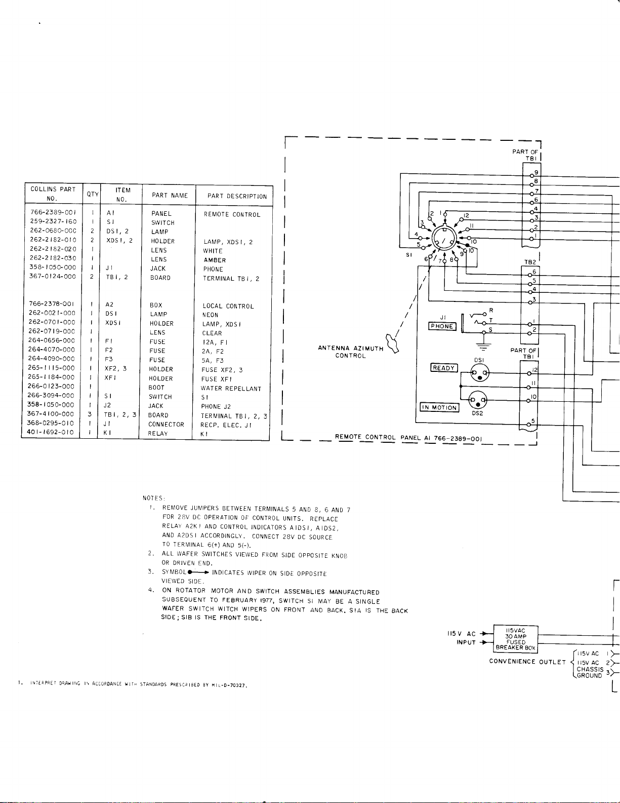
r
I
PART
OF .
TBI
-t
I
COLLINS PART
N0.
766-238e-oc
I
259-2327-t6a I I
262-o6eO-occ
262-2
tlz-ata
262-2182-o2a
262-2t82-a3a
358-r05o-ooc
367-0t24-Oaa
766-2378-00
262-002
262-07a
262-A7
2
64-
264-4C7
2
64-4
26s-t
265-
266-0
t9-aoc
065
09 0-
r
ts-000
r
I 84-000
I 23-000
t-000
t
-aaa
6- 000
a-aa0
000
I
266-3094-000
358- r
050-000
367-4 r
00-000
368-0295-0
I
0
40r-r692-0I0
I
I 2
I 2
I t
I t
I
|
QTY
I
I
I
I
ITEM
N0.
I
AI
SI
DS I, J
XDS I,
I
JI
2
TBI,
I
A2
I
DSI
I
XDS
I
I
I
FI
I
F2
I
F3
I
xF2,
I
XFI
I
SI
J2
TBI,
JI
KI
PART
NAME
PANE
L
SWITCH
2
LA I\,1P
2
HO LD
ER
LEN
S
LENS
JACK
2
BOAR
D
BOX
LAMP
HO LDER
LENS
FUSE
FUSE
FU
3
2
SE
HO LDER
HOLDER
BOOT
SWIT
CH
JACK
3
BOARD
CON N
ECTOR
RELAY
PART
REI\,1OTE
LAI\,1P,
WHIT
E
AMBER
PHONE
TERI\,4INAL
LOCAL
N
EON
LAMP,
C LEAR
I2A,
F I
2A,
F2
54, F3
FUSE
XF2,
FUSE
XF I
WATER
SI
PHONE
J2
TERMINAL
RECP.
ELEC.
KI
DESCRIPTION
CONIROL
XDSI,2
TB I,
CONTROL
XDS I
3
REPELLANT
TB I, 2,
J I
I
I
I
I
I
I
I
I
I
I
I
I
I
I
L
ANTENNA
REMOTE
AZIMUTH
CONIROL
(
L
M[FPRtI
DUwtrc t\
ACC0RDANCT
!]rB
NOTES:
I.
2.
3.
VIEWED
4.
SIDE;
STANDAROS
REIUOVE
JUIVPERS
FOR
28V
RELAY
AND
r0
ALL
OR
DC OPERATION
A2K I
A2DSI
TERMINAL
Ti/AFER
DRIVEN
ACCORDINGLY.
SWITCHES
END.
SY[ilB0Lo-+
SIDF
ON ROTATOR
SUBSEQUENT
WAFER
SWITCH WITCH
SIB lS THE
pRESCatSEO
BETWEEN
AND
CONTROL
6(+)
AND
5G).
VIEWED
INDtCATES
]\4OTOR
AND
TO FEBRUARY
FRONT
8y
ftL_0-70327.
TERI,1INALS
OF
CONTROL
INDICATORS
CONNECT
WtpER
SWITCH
WIPERS
SIDE.
FROIV]
ON
1977,
SWITCH
ON FRONT
5 AND
UNITS.
REPLACE
AIDSI,
2BV
DC
SOURCE
SIDE
OPPOSITE
StDE
OppOStTE
ASSEMBLIES
SI MAY
AND
8,
6 AND 7
AIDS2,
KNOB
MANUFACTURED
BE A SINGLE
BACK.
SIA
IS
THE
BACK
l15
v
ac
INPUT

theory
of
'
T
I
lr-
I82
TBI
r
I
l-=
l-
-no-raroi-uoroT-aF6-s-wrcrif
6SE-MBLy-A4]Gi-zizg-o6i
LET
[r:vac
I,5VAC
<
I CHASSIS
(oRouuo
t-
I
I
;------.]
2>-+----.-J
r
-r
t/--
L
L
-l
oNl
lPowER
pxore
I
I I
r:l I
I
f
+
:3\-R0-
12m.tq
F3
Fr
avo
5
2 AMp
BOX A2 766-2378-O0t
lLocAL-bNl
_l
-G
r2
t-
I
TI
PHOTO
_J
CELL
L_
OBSTRUCTION
5r5-8453-00
LIGHTS 43
I
Figure 4-9.
Revised
1
August
1434-3
1972
Antenna
Rotator Control,
Schematic
Diagram.
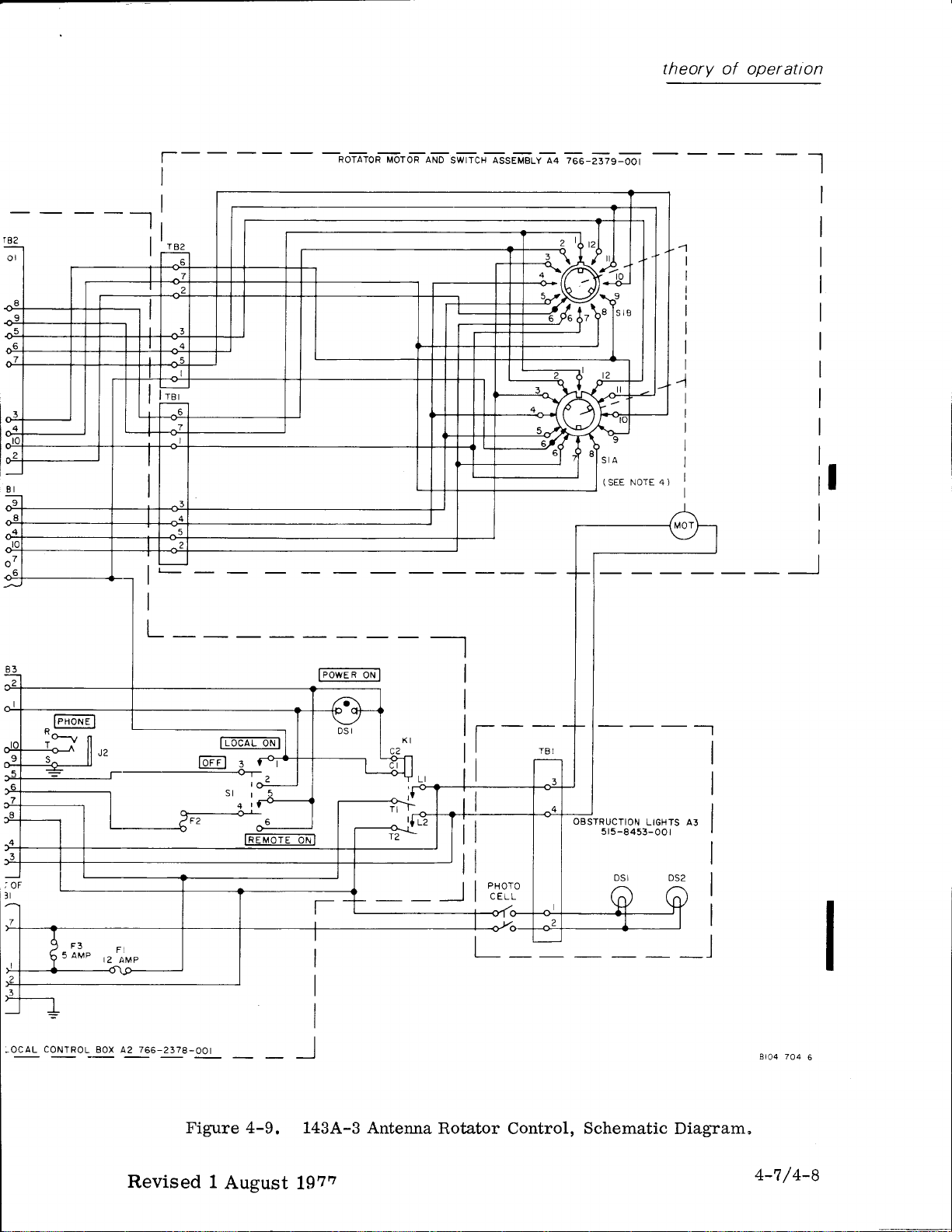
theory
of operatton
t82
rl
lr
l-
I
r
I
jro-raron-]il-oroT-ail6-swr-rcriGseTE'uv-rq-zso-lIg-i6'i
I
I
I
I
I
I
I
I
I
I
lr
I
I
__i
i,ot
;
-ocAL
F3
5 AMP
coNTR0L
L
-
F
t2 AMP
Box A2 766-2378-O0t
l'LitIL
loFEl
:
-,.:-
fa
oN
R
oN
lFowE
I
I
I
I
'I
T
T]
?
pxoro
t I
|
cELL
|
OBSTRUCTION
5r5-8453-00
LIGHTS A3
I
Br04 704
6
Figure 4-9.
Revised 1
August
1434-3 Antenna
1972
Rotator Control,
Schematic
Diagram.
4-7
/
4-8
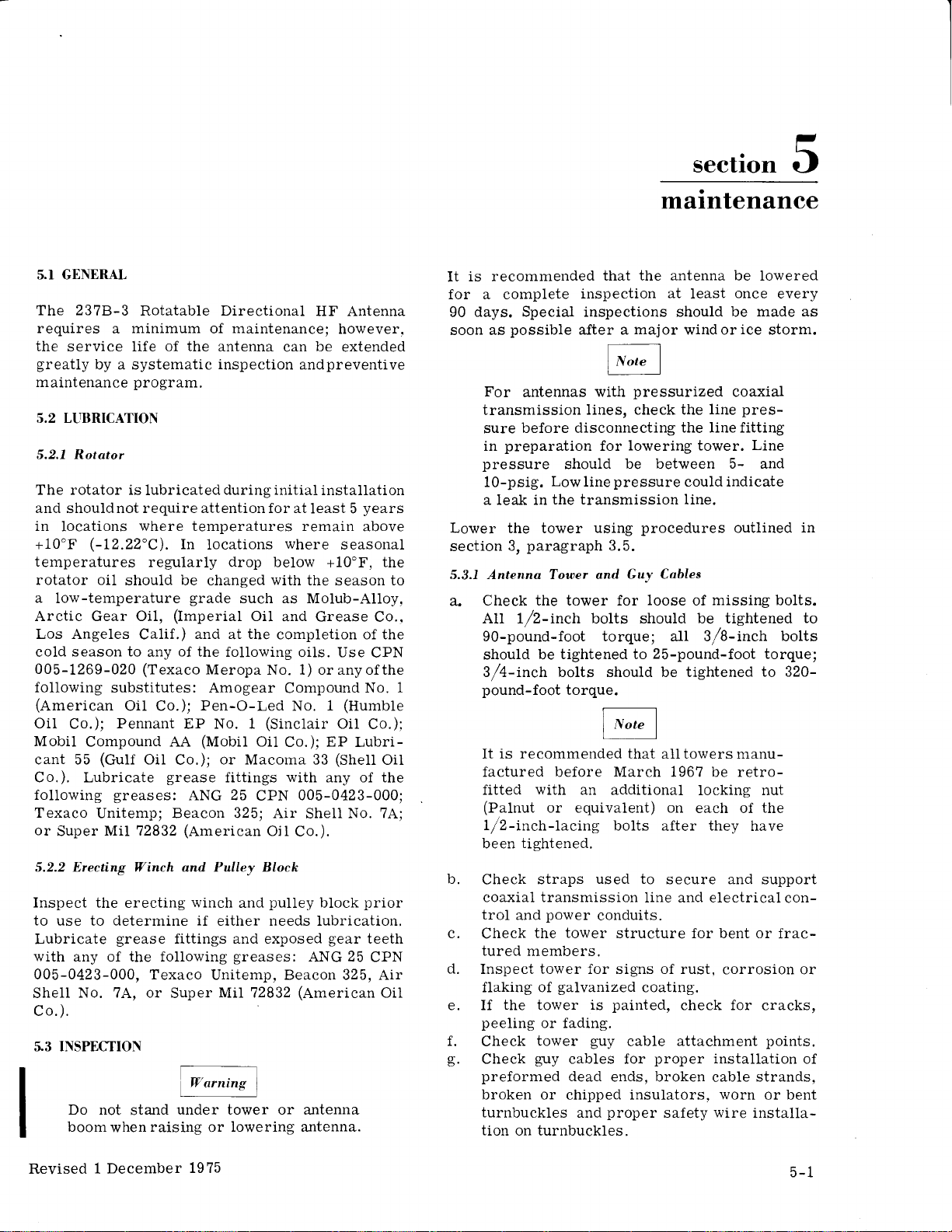
section 5
maintenance
5.T GENERAL
The 2378-3
requires
the
service life
greatly
maintenance
5.2 LLIBRICATION
5.2,7 Rotator
The rotator is
and shouldnot require attentionfor at
in
locations
+10'F
(-12.22"C).
temperatures
rotator oil
a
low-temperature
Arctic Gear Oil,
Los Angeles
season to
cold
005-1269-020
following
(American
Oil
Co.);
Mobil
Compound AA
cant 55
Co.). Lubricate
following
Texaco
or
Super
5.2.2 Erecting Winch and Pulley Block
Inspect the
to
use to
Lubricate
with
any of the following
005-0423-000, Texaco
No. 7A, or
Shell
co.).
INSPECTION
Rotatabie Directional
minimum
a
of the
by a systematic
program.
lubricated
where
In
mai.ntenance;
of
antenna
inspection
during initial
temperatures remain
locations
can
where
regularly drop below
should be changed
grade
(Imperiat
Calif.)
any
(Texaco
and
of the
Meropa No. 1) or any of the
substitutes: Amogear
Oil Co.);
Pennant
Pen-O-Led
EP No. 1
(Mobil
(GuIf
OiI
grease
greases:
Unitemp; Beacon 325; Air
MlL72832
erecting
determine if
grease
or Macoma
Co.);
ANG 25
(American
winch
ei.ther needs lubrication.
fittings and exposed
with
such as Molub-Alloy,
Oil
and
the
at
following
completion of the
Compound
(Sinclair
Oil
Co.); EP Lubri-
fittings
and
with
CPN
Ojt
pulley
greases:
Unitemp, Beacon 325, Air
Super
MiI 72832
No.
'3
V
arnins
i
Do not
boomwhen raising
under tower or antenna
stand
or
I
lowering antenna.
HF Antenna
however.
be
extended
andpreventive
installation
least 5
years
above
seasonal
+10'F,
the season to
Grease Co.,
oils. Use
33
005-0423-000;
Shel1
Co.).
block
ANG
(American
CPN
No.
(Humble
1
Oil
Co.);
(Shell
any of the
No. 7A;
prior
gear
teeth
25
CPN
Oil
the
Oil
is recommended
It
for a complete
days. Special inspections should be
90
soon as
possible
For
antennas
transmission
before disconnecting
sure
preparation
in
pressure
10-psig.
a leak in
Lower
section
5.3.7 Antenna Tower and
Check the tower for
a.
Low
the transmission line.
the tower
paragraph
3,
All \/2-inch
that the antenna be lowered
inspection
aJter a
with
lines, check the
for
should
pressure
line
using
3.5.
bolts
at
least
major
wind or
pressurized
line
the line fitting
lowering tower.
be between 5- and
could indicate
procedures
Cuy Cables
loose
should be tightened
missing
of
once
every
made as
ice
storm.
coaxia-l
pres-
Line
outlined
bolts.
in
to
90-pound-foot torque; all 3f8-inch bolts
should be
tightened to
3/4-inch bolts should be tightened
1
pound-foot
It is
torque.
recommended that
25-pound-foot torque;
to 320-
alltowers manu-
factured before March 1967 be retro-
fitted
(Palnut
1/2-inch-lacing
been
b.
Check
coaxial transmission
trol
c.
Check
tured
d.
Inspect tower for signs of rust,
flaking of
e. If
peeling
f.
Check
g.
Check
preformed
broken or chipped insulators.
turnbuckles
tion
with
an additional
or equivalent) on
tightened.
straps
power
and
the
members.
the
tower
or fading.
tower
guy
on turnbuckles.
used to
tower
galvanized
is
guy
cables for
dead
and
locking nut
each of
bolts
after
they
secure and support
line and electrical
conduits.
structure for bent or
corrosion or
coating.
painted,
cable
ends, broken
check for
attachment
proper
installation
cable
worn
proper
safety
wire
the
have
con-
frac-
cracks,
points.
of
strands,
or bent
i.nstalla-
Revised 1 December
1975
5-1

matntenance
h.
Check obstruction light fixture for
lens,
clogged
or bulbs that
recommended 6-month interval.
i.
Check
at
ductor
The following inspectionprocedures
tain
grounding
ground
should be
to the antenna tower andguyassem-
blies but
erecting the antenna and afterinspection
of the
After
l.
front
use the turnbuckles
until
When
the tower
rotator
the
guys
all slack is removed.
tightening
If tower is out of
tighten
tension and verticality.
k. Place
guy
pounds,
lower front
pounds,
to
2600
to
opposing
reaches 1500
aII
tolerance.
5.3.2
Rotator
Perform
tower in the
a.
Check
opposing
a strand dynamometer on the upper
and adjust
+15
front
pounds,
lower side
guys
to ensure that their tension
the following rotator
lowered
the tightness of the four 3/4-inch-
drain
holes, burned out bulbs
have not been replaced at the
connection at
electrode,
only be
can
and
antenna has been erected and the
connected to their
(ground
number
performed
antenna
to hand tighten the
guys,
continuously
tower
strap or con-
4 AWG or larger).
array.
groundanchors,
for any out-of-plumbtendency.
percent.
+15
percent.
upper
guys,
plumb,
guys
to maintain
front
Move dynamometer to
guy
and adjust tension
Move dynamometer back
guy
and increase tension to
percent.
t15
guys.
Alternating
increase the tension until it
pounds,
position:
+15
alternately
guy
tension to 2000
Movedynanometer
percent.
inspections
rotator mounting bolts. Torque onthesebolts
gear
tightness
pound-feet.
the
box
of
mounting
25-pound-feet.
eight 3/8-inch-
bolts.
ot S/t6-t8 nuts onthetie
these nuts should be
on
should be 320
b.
Check
rotator
these
c.
Check
rods.
+10
the tightness
bolts should be
the
Torque
pound-inches.
cracked
1eg and
per-
after
guys
watch
equal
to 1500
between the
Recheck
within
is
withthe
Torque on
100
d.
Remove switch
by 9/16
pressurized
removed if
surized.
Disconnect
e,
(item
S/t6-incn by
the adapter.
transmission
access
presence
permit passage
transmission
no
hole exists, dril1
the
Teflon insulator
screw is installed for
Replace switch
2, figure
to the
cover and check
coaxial
the transmission
the transmission
2-9) by removing the
18
nuts holding the 90"
figure
See
line to one side to
adapter. Inspect
of
an air hole in the Teflon to
of dry
line and boom assembly.
before reconnecting
the
adapter.
f.
Carefully inspect
signs of oil
oil
leakage is
leakage. If evidence
Product Line
Radio
las,
Check
C.
and
h.
Check
signs of
i,
After antenna i.s erected,
check rotator operationusingthe
Group, Rockwell
Texas 75207,
power
the
loose fitting.
the
rotating
wear
entire
discovered,
Program
Phone
and
control cables for fraying
or
binding.
control box and the 1434-3
Control
tween
sound-powered or other
instruments.
5.3.3 Antenna
With the
inspection
a. Inspect the
signs of arcing,
cracked
b.
Check
hardware
mum
insulator
will
Element number
notch be filed
c.
Check
mounting
should
Do not overtighten.
(remote).
local and remote
Aruay
antenna
of the
boom and
Coordinate operations be-
lowered,
antenna array:
and for
components.
that
each element
clears
the
of one-fourth-inch.
mounting
permit
this
bolts and
clearance
9 may require
in its adjacent
all feedline-to-element
bolts for tightness.
be
tightened to 8
that 10/32
antenna
transmission
line
cover.
line from adapter
2-9.
(or
air
1/8-inch
a
for air or
the transmission
rotator
lines or
is
elbow
Position
adapter for
gas)
hole through
gas
passage
body
of severe
contactHFAntenna
Manager,
International,
214-690-5029.
coaxial
guyed
Antenna Rotator
positions
suitable telephone
perform
element insulators
loose, broken or
and
boom
lacing by a mini-
Repositioning
elementU-bolts
with
pound-inch
joint
cable
andplumbed,
local
plug-in,
with
the
following
its
associated
one exception,
that
a curved
lacing strap.
jumper
These
with
unpres-
four
the
provide
between
to
line
for
Collinsl
Dal-l
for
rotator
for
of
strap
bolts
torque.
to
If
I
5-2
Revised
1 December
1975

matntenance
d.
Check continuitv
element.
0.1 ohm.
e.
Check
connect contact
Resistance
the tilting
between feedline
should be less than
platform
spring
assembly
tightness.
for
contact is loose, it may be retightened
removing
ing the shaft on the
item 15, figure 2-4.
See
f.
Check
removing the 90"
by
balun. Raise
assembly slightly
moisuture is
drained
prior
sembly. If
balun are not
or
low
condensation
the
bottom of
The
tower
hole
the 90"
the antenna is
o
Prior
outer mating surface
conducting
DC-4
leakage.
h.
Erect
paragraph
in
the contact assembly
opposite the
side
the interior of the balun for moisture
elbows at the rear of the
the
forward end of the boom
to
assist drai.nage. If any
present
purged
and
to reconnection
the transmission
to
power
drain
the
boom andbalun are invertedwhen the
is in the lowered
elbow
to
erecting
be
which
erected.
should
in thebalun, itshouldbe
with
dry
air or nitrogen
the
of
line system and
pressurized (for
be
operation only) a 1/8-inch-
hole
should be
lower 90"
elbow.
position.
drilled
in the
will
be lowest
the
antenna, be sure the
of the tilting
gasket
silicone
the antenna using
2.7
is
liberally
grease (to
procedures
of. section 2.
prevent pressure
and each
rf dis-
tighten-
and
spring.
90"
elbow as-
receive
drilled
The
bottom of
when
platform
coated
outlined
If the
by
in
with
for the
position.
see that it
position.
change of the azimuth
indicator
goes
control
3.4,
5.3.5 Obstruction Light
Inspect the
dirty
photocell
sensing unit
The obstruction
cover
off. To make
electric
which
at
Optimum light
candle
The
the rear
s.4 ANTENNA TOWER COATING/PAINTING
Antenna towers such as that
often require
added
or
warning
involved: surface
cation,
cation.
mended methods of applying these
antenna to rotate to
the
Check
corresponds to the
Observe that
actual antenna direction
with
control,
lights for
off, and the
needs recalibration, refer to
approximately 5 seconds;
READY indicator
Control
photoelectric
glass
cover.
operation by
Make a daylight
with
a dark
covering
lights should
and observe that the
more accurate
a
control,
lights
power;
control
of
observe the time
come
level
for turn-off,
sensitivity
the
control.
onatduskandgo
for
adjustment
See
coating/painting,
protection
to
comply
and,/or
primer
The followingprocedures describe recom-
against environmental
with
civil
clearance
preparation, pre-primer
application,
and stop at each
azimuth control
each 30"
the
IN MOTION
lights. If
control for broken or
the
cloth or other
go
on. Remove the
obstruction lights
check of the
and light 1eve1
turn-on is 35
light
58 +5 candle
is
figure
5-1.
ofthe2378-3antenna
either
or military
criteria.
Four steps are
and top
coatingstonew
or in-service towers.
rotation
paragraph
check of
photocell
cover.
photo-
dawn.
off at
power.
located
to
conditions
aircraft
appliappli-
coat
to
the
the
go
t5
in
give
When
middle
200
in
middle
unequal
to
5.3.4 The 1,13A.3 Antenna
raising the
guy
side
pounds.
with the
line
side
and increase to such a
cause buckllng
tensionof approximately
If side anchor loops
base hinge
guy
tensions may
of the tower.
antenna, maintain a
Rotator
After erecting the antenna,
accuracy
143A-3
Observe that the antenna
the
stopping
Revised 15
of the rotator
Antenna Rotator
control by
Control
rotates
north. Rotate azimuth
long enough
July 1971
at each
pivot,
point
Control
check
positioning
to N
to or
control
the 12
of
not
are
the
become
as
calibration
(north).
points
clockwise,
positions
the
to
SurJace
5.4.7
5,4.7,1 New Towers
rusty
Any
Preparation
surface should be
The entire surface should
water
5.4.1.2 In-Seroice Towers
Old
usi.ng
surfaces
brushing or
to remove dirt
paint
surfaces should
solvents or
should be taken to
power
and other contaminants.
light sand blasting.
sanding. The entire
should be washed with
dirt
or other
contaminants.
wire-brushed
washed
be
be completely
steel
bare
water
clear
clean.
with
clear
stripped
rusty
Any
wire
by
surface
to remove
5-3
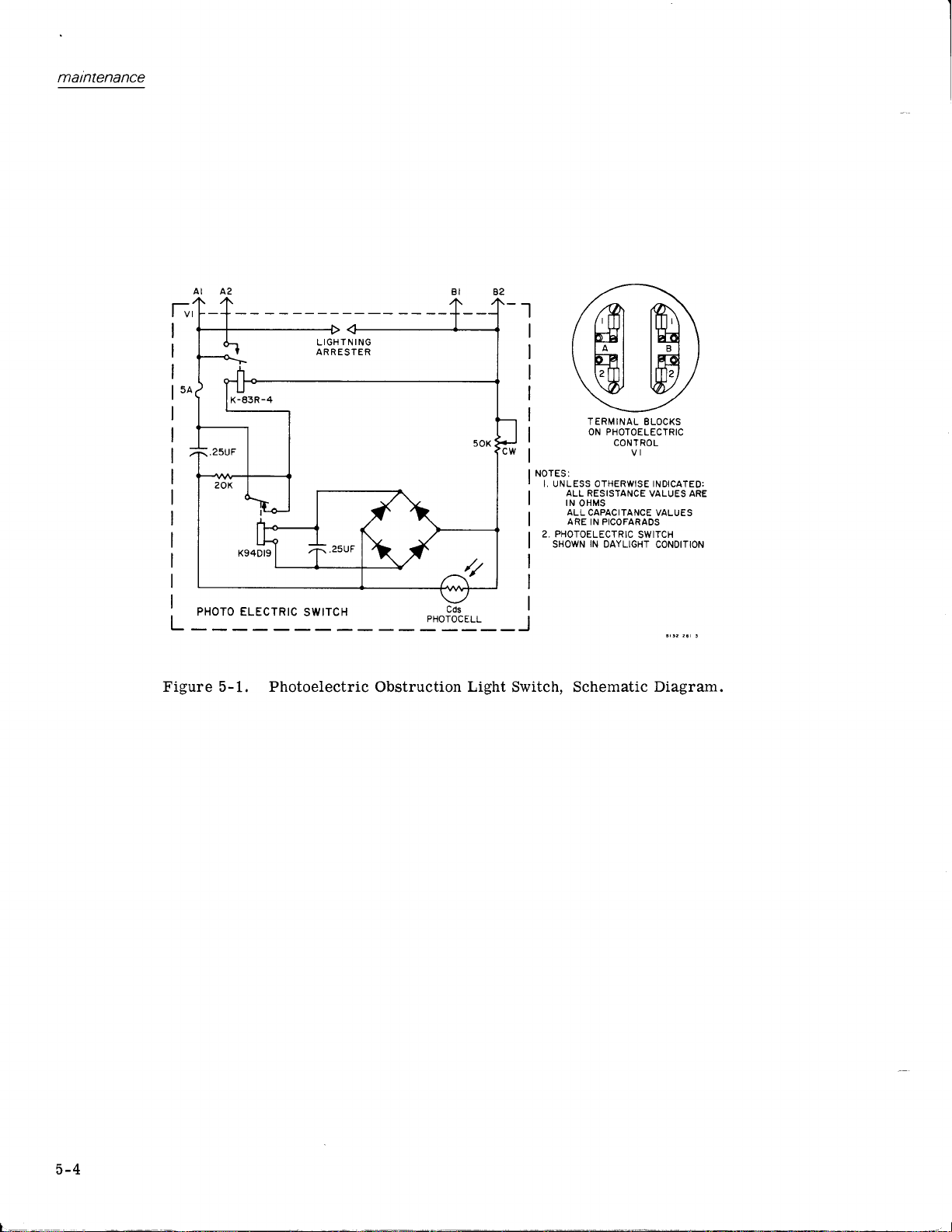
matntenance
L
PHOTO
ELECTRIC
IGHT N ING
L
ARR ESTER
SWITCH
-t
I
I
I
I
I
I
r*l
I NOTES:
I
r. ur'tLess orHERwrsE rNorcarED:
I
I
1
I
2, PHOTOELECTRIC
I
I
I
I
I
ffil
ffit
\dJ
TERMINAL
ON
ALL RESISTANCE
tt't oxus
ALL
CAPACTTANCE
ARE
IN PICOFARADS
rN
ssowru
DAYLTGHT
PHOTOELECTRIC
CONTROL
SWITCH
m
tffi
BLOCKS
VALUES
VALUES
coNotloN
ARE
Figure 5-1. Photoelectric
Obstruction
Light
Switch, Schematic
Diagram.
5-4

matntenance
@
table
See
coating
5.4.2 Pre-Primer Coat
pre-primer
The
general purpose
preparing galvanized
in
application of a
tower.
Pre-primer base
for suitable
5-1
coat
primer
primer
(Carboline
that is especially eff ective
and
(labeted
a separate container
(labeted
after mixture
the
only
5.4.2.1
Miring
Mix thoroughly
(labeled
Thin as required
using up to one-half
#
21,
5.4.2.2 Cooerage
The
180
of 2 mi1s.
The 23?8-3 tower has a surface area of approxi-
mately 410
pre-primer
of
5.4.2.3 Application
Temperature
coat should
40.56'C
a.
A)
005-1494-040,
CPN
pre-primer
square feet
Wet
).
Spraying
1. Thin,
application,
cPN
2.
For
spray equipment listed
3. Use adequate
operation of spray
4.
Hold
and
at
5. Use a 50
of the
Pot
B).
life of
is 24
amount
to be usedinthatperiod.
by volume, four
to one
square
be between 40' and
as
005-1494-040.
best results use
the spray
a right angle to, the surface.
gun.
part
for
spray
gallon
per
will
coat
gallonforadryfilm
per
application should be 8
feet.
Approximately
required.
is
during
application
required, for conventional spray
using Polyciad Thinner
air volumesupplyfor correct
gun
percent
materials for
1037 WP) is a
steel structures for
top
coat.
packedin
is
A)
from its
the
hours at 75'F.
of
catalyst
catalyst
pre-primer
Mix
parts
of
(labeled
or brush application
of
Carboline
gallon
cover
of
approximately
Thinner
pre-primer.
thickness
mils thick.
gallons
3
pre-primer
of
110'F
(4.44"
the recommended
in table
gun.
to 10 inches
8
overlap
with
5-2.
each
base
B).
and
#21,
from,
pass
coats.
t
hour at 75"F before
6.
Allow
applying
to dry for
other
b. Brushing
1.
Thin,
using Polyclad
7494-040.
2.
Use natural bristle brushes
full strokes. Avoid
If necessary in hot
stightty
5.4.3 Primer
primer
The
rust-inhibiting,
crete, and inorganic
required, for brush application,
as
#21,
and apply
workability.
Primer
for steel,
surfaces in
to
obtain
(CPN 005-1494-010)
Coat
(Rustbond
coat
universal
Thinner
rebrushing the material.
weather, thin
proper
primer
zinc-primed
CPN
material
#6C)
005-
with
is a
con-
corrosive areas.
5,4.3.7
Stir
a uniform
blixing
or mechanically shake until
consistency.
Thinning
primer
may
be required
achieves
for conventional spray or brush application.
Thinning
spray application. If
Polyclad Thinner
or
windy conditions),
PN 00
C
appli
quart per gallon
1
5.4.3.2
The
square feet
2
of
Approximately
required.
5.4.3.3 Application
Do not apply
below +40'F
tion
used may be increased.
a.
1.
2.
3. HoId
is not normally required for airless
#8,
CPN
5
1 494-060
-
ed solvent-s ensitive
Coaerage
primer
Wet
mils.
(below
Spraying.
coat
ventional
+60oF,
may
(for
primer.
of
will
coat
per
gallon
appiication should
gallons
3
primer
(+4.44"p).
coat
+4.44"C) the
Spray
performed
be
or
airless method of application.
thinning
005-1494-050
or
Carboline Thinner
appli cation over
paints
cover approximately 200
for a
of
when temperatures
For cool
application of
using either
required,
is
(for
previously
thinner up to
Us e
).
dry
be
primer
weather applica-
quantity
thickness
film
8 mils thick.
coat are
thinner
of
primer
the
the
For best results use the recommended
spray equipment
Use adequate air
operation
(conventional
the
of spray
gun
8to l0inches fromthe surface
spray), or
listed
volume
gun.
in table 5-3.
supplyfor correct
12 to 15 inches
use
hot
#25,
are
con-
5-5

maintenance
COLLINS
PART NUMBER
005-1494-010
005-1
494-020
005-1494-030
005-i494-040
005-1494-050
005-1 494-060
005-1494-070
005-1494-080
005-1494-090
005-1494- 100
Table 5-1. Recommended
DESCRIPTION CARBOLINE
Primer
Paint
Paint
orange)
Thinner
Thinner
Thinner
Wash
Paint
(international
(international
primer
(medium gray)
white)
Tower
TYPE
Rustbond
Carboiine
Carboline
Polyc1ad thinner
Po1yclad thinner
Carboline
Carboline
Carboline
(gray
*Paint
*Paint
kit:
Consists
following
the indicated
volume.
-070
-010
-020
-030
-040
-060
kit:
following
the indicated
volume.
-070
-010
-080
-040
-060
materials in
Wash
Primer
Paint
Paint
Thinner
Thinner
Consists
materials in
Wash
Primer
Paint
Thinner
Thinner
of the
ratio by
primer
(int
white)
(int
orange)
of the
ratio by
primer
(gruy)
N/A
Coatings.
primer
1294
1294
thinner
1037 WP
1294
724)
#6C
#21
#8
#25
OF
UNIT
MEASURE
(06)
cal
(06)
GaI
(06)
ca1
(06)
Ga1
(06)
Gal
(06)
cal
(06)
Gal
(06)
cal
Pieces
3
4
3
3
1
(07)
2-L/2
3
4
6
1
2-1/2
WT
(Ib)
10.5
11
11
10.5
10.0
10.0
10.5
11
N/A
*Specify
container
(airless
surface,
spray),
4. Use a 50
gun.
the
of
5. Coat
the edges of beams and
surfaces
b. Brushing. Use
apply
with
size in addition
percent
first, making another
natural bristle brushes and
fuIl strokes. Avoid
the material. If necessary
thin material slightly
ability.
5.4.3.4 Drying
Ailow
(23.89'C)
5-6
a
Time
t
before top coating.
minimum drying
hour
and at a
overlap
to
obtain
right
with
in hot
proper
to vendor
angte
each
irregular
pass
rebrushing
weather,
time
at 75'F
to the
pass
later.
work-
part
number.
5.4.4 Top Coat (CPN 005-1494.XXX)
See table
and
The top
for
coat
complete Collins
coat
protection
5-1 for
(Carboline
It is resistant to dirt
gloss
color
tection, two
5.4.4.1 hlixing
Stir
achieves a
and
coats are
or mechanically shake until top coating
uniform
desired
Part Number.
1294) is a
of surfaces in
pickup
retention. For
required.
consistency.
coIor,
quantity,
generalpurpose
corrosive
and has excellent
maximum
Top coat
Revised
15
JuIy 1971
areas.
pro-
may
be

matntenance
Table
TYPE
Conventional
5-2. Spraying
OF
TYPE OF
Conventional
Airless
SPRAY
SPRAY
Equipment,
GUNS
Carboline
Binks #18 or #19
DeVilbiss
Tab1e
GUNS FLUID
Binks
P-MBC
5-3. Spraying
or
#18
#19
or JGA FX
DeVilbiss P-MBC or JGA
DeVilbiss
Graco
JGA 5026
205-762
1037 WP Wash Primer
FLUID TIP
638 63PB
Equipment,
638
FX
a
Use
psi.
2000
AIR CAP AIR HOSE
704
Rustbond
TIP
AIR CAP AIR HOSE
63PB
704
0.013orifice
and
Carboline
ID
b/16
d/t6
Primer 6C.
ID
5h6
5/16
and
3/8
(in.)
(in.)
1294
Top
MATL HOSE
(in.)
ID
3/8
3/s
MATL
(in.)
ID
3/8
3/8
t/4
Coat.
HOSE
thinned with up to 1
Thinner #21,
or spray
5.4.4.2 Coaerage
The
feet
application
gallons
6
5.4.4.3 Application
application.
top
coat
per gallon
should
are required for the two
quart per gallon
005-1494-040, for
CPN
will
cover approximately
for 3-mi1 dry-film thickness. Wet
be 8 mils thick.
Temperature during application of
be between 40'and
a..
Spraying:
1.
Thin as
required
110'F
(4.44"
and 43.34'C).
for conventional
using Polyclad
eitherbrush
165square
Approximately
coats.
top
coat should
spray
application
cPN
2.
For best results use the recommended
spray equipment listed in table
3.
Use adequate air volume supply for
operation
4.
Hold
and at a
5. Use a
gun.
the
6.
Al1ow to dry for 4
before applying
b. Brushing
1.
Thin
using Polyclad
7494-040.
2,
Use a natural
full brush
rebrushing.
using Polyclad Thinner
005-1494-040.
gun.
8 to 10 inches from,
to,
the
surface.
overlap
hours
with
at 70'F
for brush application,
Thinner
#2L,
brush.
the
50
as
right
percent
the
of
spray
spray
gun
angle
second coat.
required
bristle
using short strokes and avoid
5-2.
each
(21.11'C)
CPN
Apply
#27,
correct
pass
of
005-
with
a
5-7
/5-8

I
ff.vrt{;{
e,t:
ri
.-J-
o i t ,' .s"t f,,.'-
/
*
Vt40
t"ll'ff
,;^l
t*
t'
or"u
,
ClS)_:
v.7
(,
{-
5;''rt
t-4,
{
:l
T
,I
 Loading...