

Collins 212G-1 Instruction Book
523-0033000-00141A
instruction
book
212G-l
Broadcast Console
This
manual
includes:
SP-144 Broadcast Console 2126-1 523-0155412
TO-323 Preamplifier
356A-l
520-5446000
TO-324 Program/
Monitor
Amplifier
3568-1 520-5447000
TD-325
Limiter
Amplifier
356£-1 520-5448000
TO-326 Cue
Amplifier
356Q-l
523-0034000
TO-327 Relay
Unit
274K-2 523-0036000
TO-328
Power
Supply
409X
-2 523-0035000
flJ
Collin
s R
adio Company
1960
. fl}62
Cedar Rapids Division I Collins Radio Company. Cedar Rapids, Iowa
p"n,.d.n
u.s
.~
I
,
j
1
SYSTEM INSTRUCTIONS
5P-144
4th
EDITION,
15
OCTOBER
1961
BROADCAST
CONSOLE
212G-l
©COLLINS RADIO
COMPANY
CEDAR RAPIDS,
IOWA,
U.S.A.
1960,
1961
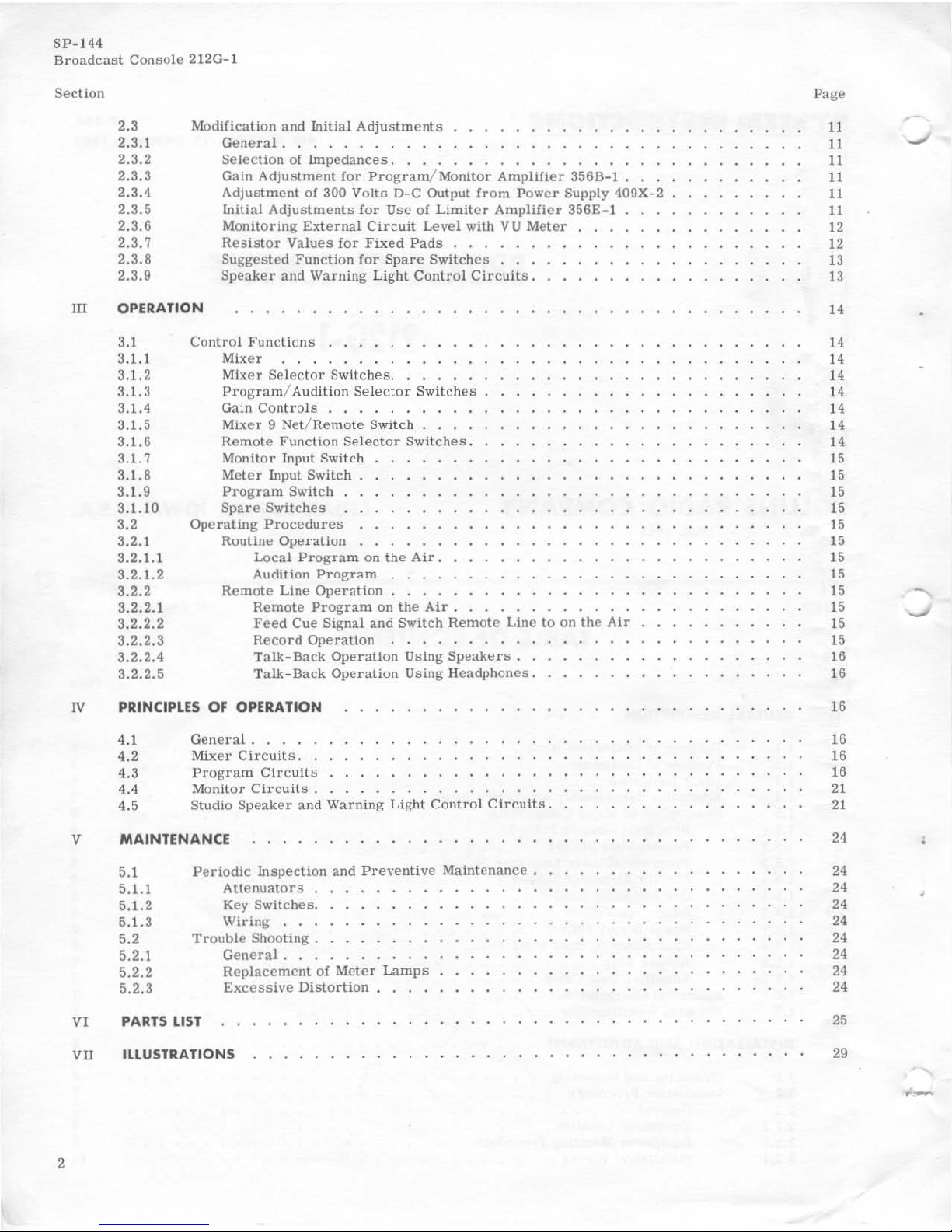
TABLE
OF CONTENTS
Section
1
II
GENERAL DESCRIPTION
I.I
1.2
1.3
1.4
1.5
1.5.1
1.5.2
1.5.3
1.5.4
1.5.5
1.5.6
1.5.7
1.5.8
1.5.9
1.5.10
1.6
1.7
Purpose
of
Instruction
Book
Purpose
of
Equipment.
. .
Basic
Equipment
. . . . .
Applicable
Subassembly
Instruction
Books.
Description
of
Major
Components.
. . .
Broadcast
Console
212G-l
....
.
Preamplifier
356A-l
......
.
Program/Monitor
Amplifier
356B-1.
Limiter
Amplifier
356E-l
Cue
Amplifier
356Q-l
...
Relay
Unit 274K-2 . . . .
Power
Supply
409X-2
. . .
Rack Mounting Shelf
499G-l
Jumper
Plug.
. . . .
Amplifier
Test
Cable
.
Electrical
Characteristics.
Physical
Specifications
.
INSTALLATION
AND
ADJUSTMENT
2.1
2.2
2.2.1
2.2.2
2.2.3
2.2.4
Unpacking and
Inspecting
Installation
Procedure
General
. . . . . •
Equipment
Location.
Equipment
Mounting
Procedure
Installation
Wiring
. . . . . .
Page
5
5
5
5
6
6
6
6
6
6
6
6
6
6
6
7
7
8
8
8
8
8
8
8
10
SP-144
Broadcast
Console 212G-l
Section
2
III
2.3 Modification and
Initial
Adjustments
...........
.
2.3.1
General.
. .
..
.
...............
.
2.3.2
Selection
of
Impedances
...............
.
2.3.3 Gain
Adjustment
for
Program/Monitor
Amplifier
356B-l
.
2.3.4
Adjustment
of
300 Volts D-C Output
from
Power Supply 409X-2
2.3.5
lnllial
Adjustments
for
Use
of
Limiter
Amplifier
356E-
l
2.3.6
Monitoring
External
Circuit
Level
with
VU
Meter
2.3.7
Resistor
Values
for
Fixed
Pads
.....
.
2.3.8
Suggested
Function
for
Spare
Switches
..
.
2.3.9
Speaker
and
Warning
Light
Control
Circuits.
OPERATION
3.1
3.1.1
3.1.2
3.1.3
3.1.4
3.1.5
3.1.6
3.1. 7
3.1 .8
3. 1.9
3.1.10
3.2
3.2.1
3.2.1.1
3.2.1.2
3.2.2
3.2.2.1
3.2.2.2
3.2.2.3
3.2.2.4
3.2.2.5
Control
Functions
Mixer
Mixer
Selector
Switches.
. . . . .
Program
/ Audition
Selector
Switches
Gain
Controls
. . . . . . . . . .
Mixer
9 Net/
Remote
Switch.
. . .
Remote
Function
Selector
Switches.
Monitor
Input Switch
Meter
Input Switch
Program
Switch .
Spare
Switches
Operating
Procedures
Routine
Operation
Local
Program
on
the
Air.
Audition
Program
. . . .
Remote
Line
Operation
. . . .
Remote
Program
on
the
Air.
Feed
Cue
Signal and
Switch
Remote
Line
to
on
the
Air
Record
Operation
. . . . . . . . . .
Talk-Back
Operation
Using
Speakers
..
Talk-Back
Operation
Using
Headphones.
IV
PRINCIPUS
OF OPERATION
4.1
General.
. . . .
4.2
Mixer
Circuits
..
4.3
Program
Circuits
4.4
Monitor
Circuits.
4.5 Studio
Speaker
and
Warning
Light
Control
Circuits.
v
MAINTENANCE
5.1
Periodic
Inspection
and
Preventive
Maintenance.
5.1.1
Attenuators
.
5.1.2 Key
Switches.
5.1.3
Wiring
...
5.2
Trouble
Shooting.
5.2.1
General
...
5.2.2
Repla
ceme
nt
of
Meter
Lamps
5.2.3
Excessive
Distortion
VI PARTS
LIST
VII ILLUSTRATIONS
Page
11
11
,....
..J
11
11
11
11
12
12
13
13
I.
I.
I.
I.
I.
I.
I'
I.
15
15
15
15
15
15
15
15
15
15
15
15
16
16
16
16
16
16
21
21
24
24
24
24
24
24
24
24
24
25
29
.-
•
,
Figure
1-1
2-1
2-2
2-3
2-4
3-1
4-1
4-2
4-3
4-4
4-5
6-1
6-2
6-3
6-4
7-1
7-2
7-3
Table
1-1
1-2
1-3
1-4
2-1
2-2
2-3
LI
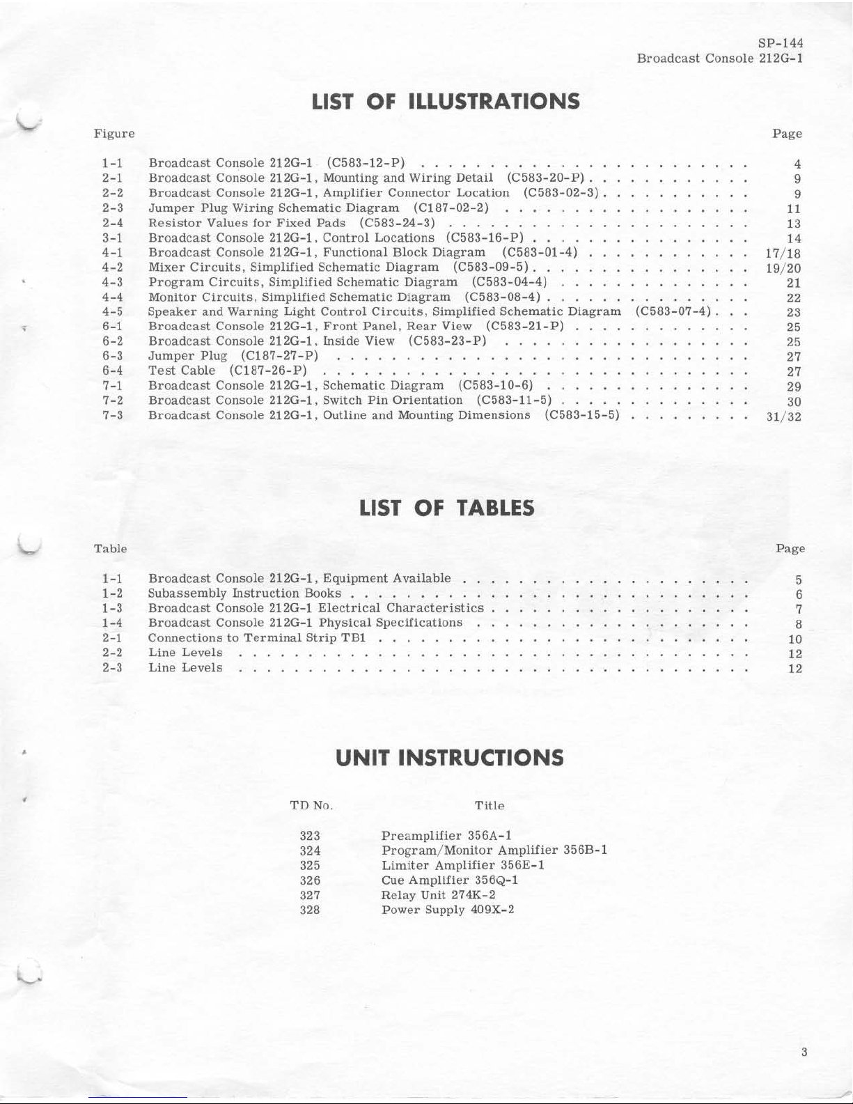
ST OF ILLUSTRATIONS
Broadcast
Console
2120-1
(C583-12-P)
.............
.
Broadcast
Console
2120-1,
Mounting
and
Wiring
Detail
(C583-20-P)
..
Broadcast
Console
2120-1.
Amplifier
Connector
Location
(C583-02-3).
Jumper
Plug
Wiring
Schematic
Diagram
(C187-02-2)
Resistor
Values
for
Fixed
Pads
(C583-24-3)
..
.
.....
.
Broadcast
Console
2120-1,
Control
Locations
(C583-16-P)
...
,
Broadcast
Console
2120-1,
Functional
Block
Diagram
(C583-01-4)
Mixer
Circuits,
Simplified
Schematic
Diagram
(C583-
09-5)
..
Program
Circuits,
Simplified
Schomatic
Diagram
(C583-04-4)
..
Monitor
Circuits,
Simplified
Schematic
Diagram
(C583-08-4)
.•.
SP-144
Broadcast
Console
2120-1
Page
4
9
9
11
13
14
Speaker
and
Warning
Light
Control
Circuits,
Simplified
Schematic
Diagram
(C583-07-4).
Broadcast
Console
2120-1.
Front
Panel.
Rear
View
(C583-21-P)
17/ 18
19/ 20
21
22
23
25
25
27
27
29
30
Broadcast
Console
2120-1,
Inside
View
(C583-23-P)
Jumper
Plug
(C187-27-P)
.......••......
Test
Cable
(CI87-26-P)
...............
.
Broadcast
Console
2120
-1,
Schematic
Diagram
(C583-10-6)
Broadcast
Console
2120-1.
Switch
Pin
Orientation
(C583-11-5)
Broadcast
Console
2.120-1, Outline and Mounting
Dimensions
(C583-15-5)
LIST
OF
TABLES
Broadcast
Console
2120-1.
Equipment
Available
..
Subassembly
Instruction
Books . . . . . . . . . .
Broadcast
Console
2120-1
Electrical
Characteristics
Broadcast
Console
2120-1
Physical
Specifications
Connections
to
Terminal
Strip
TBI
Line
Levels
Line
Levels
. . . . . . . . . .
UNIT
INSTRUCTIONS
TD
No.
Title
323
Preamplifier
356A-l
324
Program/Monitor
Amplifier
356B-l
325
Limiter
Amplifier
356E-l
326 Cue
Amplifier
356Q- l
327
Relay
Unit 274K-2
328
Power
Supply 409X-2
31/32
Page
5
6
7
8
10
12
12
3
I
I
I
4
SP
- 144
BrOadca t
s ConsOl e 212G
_l
~--';iii~"'
____
________
_
!&
II-~
••
: .
~
.
~
••
\"
\".
"
..
-4 ...
'
~
~
,
~
.I
.I
~
:~·s
•••••
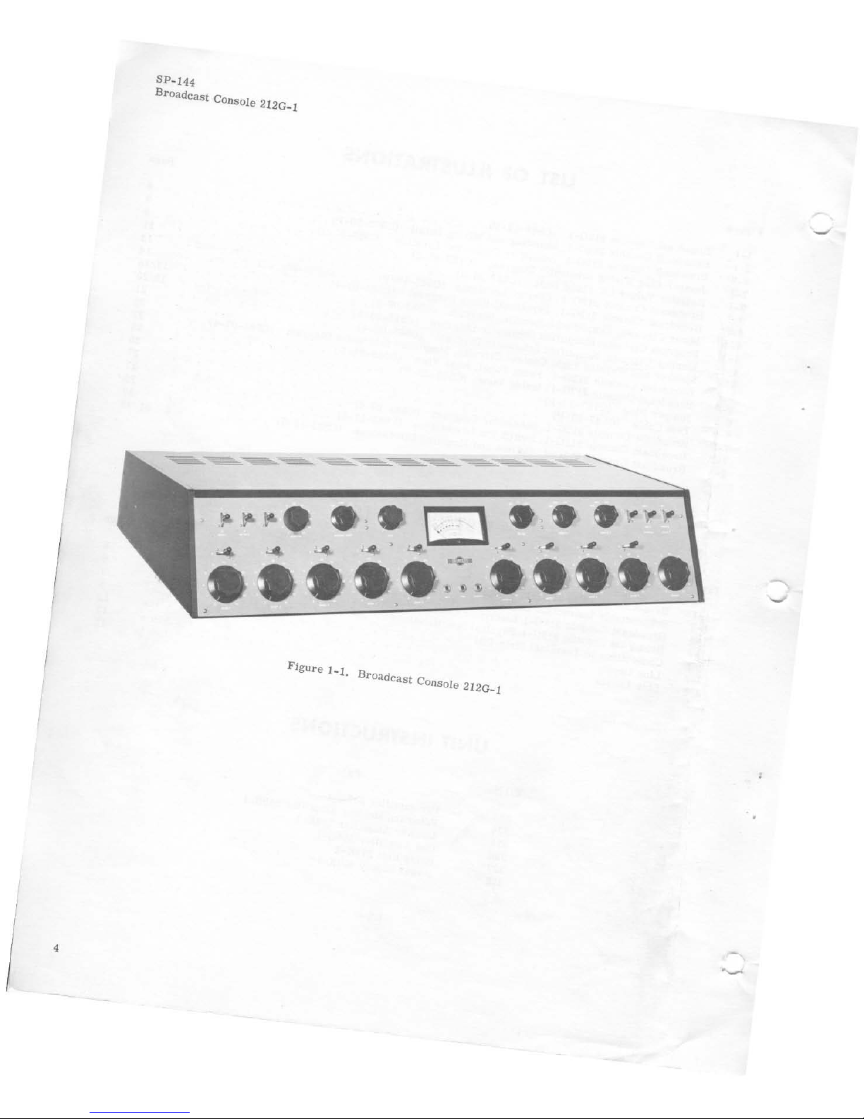
Figure
1- 1.
Broadca
t C
s OnSole 212G
_l
,
\
....
,-,.
SP
-144
Broadcast
Console
212G
-I
SECTION I
GENERAL DESCRIPTION
1.1
PURPOSE
OF
INSTRUCTION BOOK.
This
instruction
book
is
intended
to
serve
as
a guide
in
the
installation.
adjustment.
operation,
and
mainte-
nance
of
Broadcast
Console
212G-1.
1.2
PURPOSE
OF
EQUIPMENT.
Broadcast
Console
212G-l
is
designed
especially
for
use
in
high-fidelity
AM, FM,
or
TV
broadcast
instal
-
lations.
The
number
and
arrangement
of
amplifiers
may
be
selected
to
fit
Individual
requirements.
Simul-
taneous
mixing
facilities
for
auditioning
or
broadcasting
of
up to 9 of
13
possible
inputs
are
pro-
vided.
Ease
of
operation
is
assured
by
clearly
Identi-
fied
control
knobs.
The
number
of
functions
available
and
performance
are
determined
by
the
selection
of
preamplifiers
and
program/monitor
amplifiers
to
be
installed
in
the
conso
le.
1.3
BASIC
EQUIPMENT.
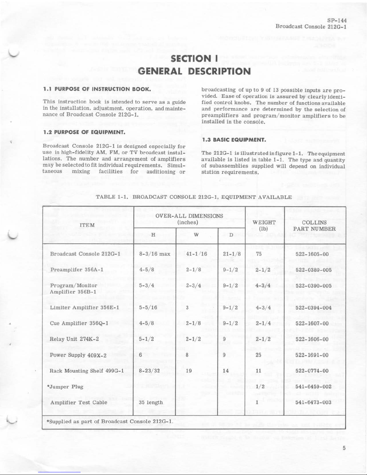
The 212G-l
is
Illustrated
in
figure
1-1.
The
equipment
available
is
listed
in
table
1- 1.
The
type
and
quantity
of
subassemblies
supplied
will
depend on
individual
station requirements.
TABLE
1-1.
BROADCAST CONSOLE 212G-
l.
EQUIPMENT AVAILABLE
OVER-ALL
DIMENSIONS
(Inches)
WEIGHT
COLLINS
ITEM
(lb)
PART
NUMBER
H W
D
Broadcast
Console
212G- l 8- 3/ 16
max
41-1 16
21-1/ 8
75
522-1605-00
Preamplifer
356A-l
4-5
/ 8
2-1/8
9-1/ 2
2-1/ 2
522-0389-005
Program/Monitor
5- 3/ 4
2-3/4
9-1/ 2
4-3/4
522-0390- 005
Amplifier
356B-l
Limiter
Amplifier
356E
-l
5-5
/ 16
3 9-
1/2
4-3
/ 4 522- 0394 - 004
Cue
Amplifier
356Q-I
4- 5/ 8
2-1/8
9-1/ 2
2-
1/ 4 522-1
607-00
Relay Unit 274K-2 5-1/ 2
2-1/ 2 9
2-
1/ 2 522- 1
606-00
Power
Supply
409X-2
6 8 9 25
522-1691-00
Rack Mounting Shelf
499G-l
8-
23/32
I'
14
11
522-0774-00
*J
umper
Plug
1/2 54
1-
6459-002
Ampl
ifier
Test
Cable 35
length
1
541-6473-003
*Supplied
as
part
of
Broadcast
Conso
le 212G-1.
5
SP-144
Broadcast
Console
212G-l
1.4
APPLICABLE
SUBASSEMBLY INSTRUCTION
BOOKS.
Applicable
subassembly
instruction
books
are
listed
in
table
1-2
and
suppUed
following
section
VII
of
this
instruction
book.
TABLE
1-2
SUBASSEMBLY INSTRUCTION BOOKS
PUBLICATION
COLLINS
PART
NUMBER
Preamplifier
356A-
l
520-5446-00
Program/Monitor
Amplifier
520-5447-00
356B-l
Limiter
Amplifier
356E-l
520-5448-00
Cue
Amplifier
356Q-l
523-0034-00
Relay
Unit
274K-2
523-0036-00
Power
Supply
409X-2
523-0035-00
1.5
DESCRIPTION OF MAJOR COMPONENTS.
1.5.1
BROADCAST CONSOLE
212G-1.
The
2l2G-l
utilizes
modular
type
construction
to
provide a choice
of
plug-In
amplifier
units
which
will
meet
individual
installation
requirements.
The
front
panel
and
top
are
hinged
to
allow
easy
access
to
all
parts.
The
2l2G-l
may
be
serviced
from
the
front
allowing
the
cabinet
to
be
almost
flush
against
a
wall
or
window.
There
should
be
about 1/2-inch
clearance
behind
the
console
to
allow
ventilation
and
to
provide
clearance
for
the top
when
open.
Slots
in
the
bottom,
back,
and
top
provide
cooling
by
con-
vection.
Space
Is
provided
for
up
to
eight
Pre-
amplifiers
356A-I,
two
Program/Monitor
Amplifiers
356B-l,
or
one
356B-l
and
one
Limiter
Amplifier
356E-l,
one
Cue
Amplifier
356Q-1.
one
Relay
Unit
274K-2,
and
one
Power
Supply
409X-2.
1.5.2
PREAMPLIFIER
356A
-1.
The
necessary
circuitry
for
two
stages
of
ampli-
fication
makes
up
this
plug-in
module.
It
provides
40
db
of
gain
from
low-level
microphone
or
trans-
cription
lines
to
feed
program,
audition,
or
cue
circuits.
Refer
to
paragraph
1.4.
1.5.3
PROGRAM/ MONITOR
AMPLIFIER
356B
-1.
The
356B
-l
has
an
over-all
gain
of
56
or
68
db
for
use
on
program
lines
or
speaker
operation.
The
de-
sired
level
is
selected
by
means
of a
toggle
switch
6
located
on
the
amplifier
chassis. The
outpu~
im
-
pedance
is
factory
wired
for
600
ohms
.
It
may
easily
be
changed
for 150-ohm
output
impedance.
Refer
to
paragraph
1.4.
1.5.4
LIMITER
AMPLIFIER
356E-1.
The
necessary
circuitry
for
two
stages
of
ampli-
fication
and a bias
rectifier
makes
up
this
plug-in
module.
It
has
an
over-all
gain
of 54 db.
The
com-
pression
ratio
is
adjustable
from a ratio
of 1.6: 1
to a ratio
of 5:1. A
choice
of
either
11
milliseconds
attack
time
and
0.9
second
release
time
or
62
milli-
seconds
attack
time
and
5.2
seconds
release
time
for
63
percent
recovery
is
provided.
Refer
to
paragraph
1.4.
1.5.5
CUE
AMPLIFIER
356Q-1.
The
necessary
circuitry
for
two
stages
of
ampli-
fication
makes
up
this
plug-in
module.
It
provides
up
to
55
db
gain
from
the
cue
line.
The
212G-l
console
provides a gain
control
for
the
356Q-l
and
a
speaker
for
the
output.
The
output
impedance
is
factory
wired
for
four
ohms.
Refer
to
paragraph
1.4.
1.5.6
RELAY
UNIT
274K-2.
The
274K-2
is a plug-In
module
which
controls
appli
-
cation
of
audio
power
tostudiospeakersanda-c
power
to
studio
warning
lights. The
four
12-volt
d-c
relays
are
mounted
on
rubber
to
minimize
noise.
Transient
suppressing
networks
across
the
relay
coils
minimize
arcing
and
radio
interference.
Referto
paragraph
1.4.
1.5.7
POWER
SUPPLY
409X-2.
The
409X-2
furnishes
power
for
filaments,
plate
cir
-
cuits,
and
relays
in
the
Broadcast
Console
212G-1.
Silicon
rectifiers
are
USed in
the
high
voltage
Circuit
to
eliminate
the
heat
associated
with
vacuum-tube
rectifiers
and
to
ensure
long
life.
The
output
of
the
409X-2
Is
as
follows:
250
to
300
volts
d-c
(adjustable)
at
250
ma,
6.3
volts
a-c
at 6 amperes,
and 12
volts
d-c
at 1 ampere.
Refer
to
paragraph
1.4.
1.5.8
RACK MOUNTING
SHELF
499G-1.
The
499G-l
consists
of a panel
and
chassis
assembly
for
use
in
an
RMA
standard
relay
rack.
The
front
panel
is a hinged
door
that
opens
downward: Base
perforations
provide
mounting
holes
to
accommodate
any
arrangement
of
small
modules
without
drilling.
A
variety
of
associated
connectors,
mounting
brackets,
and
cables
can
be
supplied.
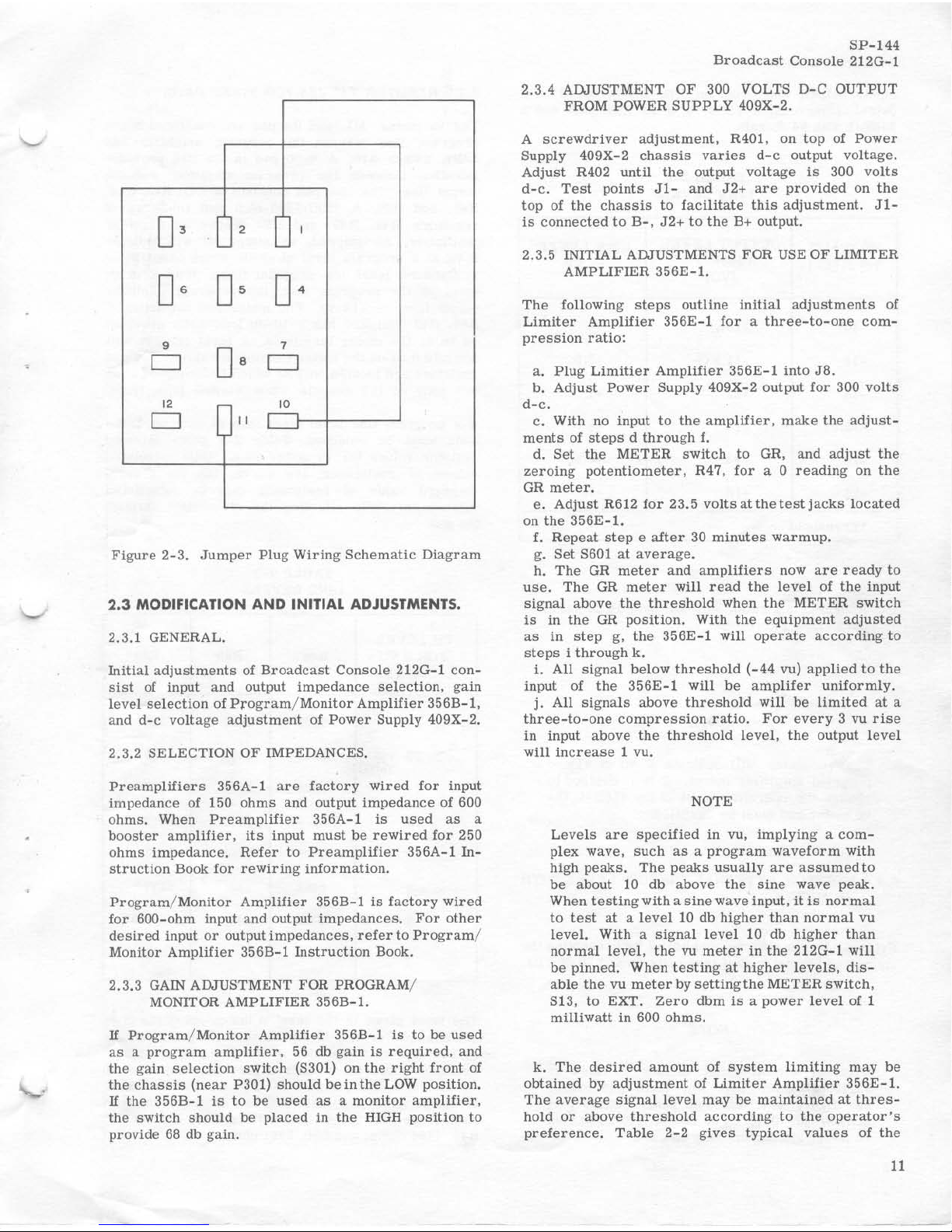
1.5.9
JUMPER
PLUG.
When
mixing
facilities
are
desired
for a program
source
that
has a self-contained
preamplifier,
it
is
necessary
to
insert a jumper
plug
into
the
jack
normally
used
for a Preamplifier
356A-l.
The
jumper
plug
wiring
schematic
diagram
is
shown
in
figure
2-3.
One
jumper
plug
is
supplied
with
Broadcast
Console
212G-1.
SP
-144
Broadcast
Console
2120-1
1.5.10
AMPLIFIER
TEST
CABLE.
' .6
ElECTRICAL
CHARACTERISTICS.
An
amplifier
test
cable
is
available
for
use
with
Broadcast
Console
2120
-1.
This
cable
is
35
inches
lon
g and
has a twelve-pin
plug
on
one
end
and a
twelve
-
pin
jack
on
the
other.
The
amplifier
test
cable
permits
operation
of
amplifier
while
it
is
out
of
the
console.
Electrical
characteristics
of
the
Broadcast
Console
2120-1
are
listed
in
table
1-3.
Thesecharacterlstics
are
measured
with
d-c
voltage
adjusted
to
300
volts.
TABLE
1-3.
BROADCAST CONSOLE
2120-1
ELECTRICAL
CHARACTERISTICS
CHARACT ERISTICS
Maximum
Number
of
Channels
Input
Impedance
Output
Impedance
Gain
Output
Level
Response
Distortion
Noise
Power
Source
DESCRIPTION
6
low-level
inputs, 2 medium
level
inputs, 1 remote
or
net
input,
1
program
channel, 1 monitor
channel.
and
one
cue
channel
when
provided
with:
8
--
Preamplifiers
356A
-l
1
--
Amplifier
356B
-l
or
356E
-I
1
--
Program/Monitor
Amplifier
356B
-l
1 --
Relay
Unit 274K - 2
1
--
Cue
Amplifier
356Q-l
1
--
Power
Supply
409X-2
Low
Leve
l:
20/
150
/ 250/ 600
ohms
balanced
or
unbalanced'"
Net/
Remote
Lines:
50/ 150/ 250 / 600
ohms
'"
Medium
Level:
600
ohms
(unbal
anced)
Line:
150/ 600
ohms
'"
Monitor:
600
ohms
Low
level
to
program
line
at
least
100 db.
Remote
line
to
program
line
at
least
53 db.
Medium
level
to
program
line
at
least
62 db,
Program
Line:
±18
dbm
(50 mw)
±1.5 db,
50-15,000
cps
at
program
line.
Less
than
1%
at
±18
dbm
at
program
line,
less
than
3%
at
+39
dbm
at
monitor
amplifier
output.
At
least
68
db
below
+18
dbm
program
outpu
t with - 50
dbm
low
level
Input.
(Equivalent
input
noise
level
-118 dbm
or
less.)
115
or
230
volts
a- c ±10%, 50/ 60
cps,
single
phase.
"'Shipped
wired
for
600
ohms
output
and
net/remote
line
impedance,
150
ohms
low-level
impedance,
and 115-
v
olt
power
source.
7
SP
-14
4
Broadcast
Console
212G- l
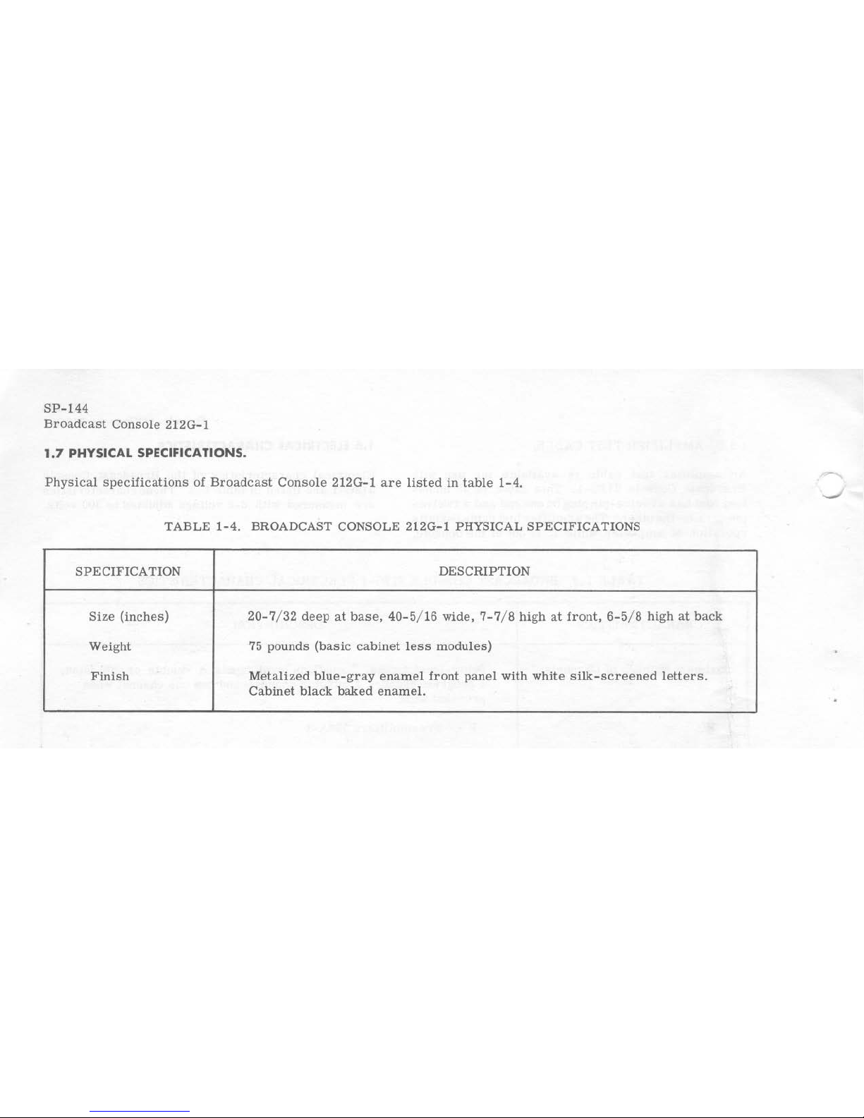
1.7
PHYSICAL SPECIFICATIONS.
Physical
specifications
of
Broadcast
Console
212G-l
are
listed
in
table
1-4.
TABLE
1-4.
BROADCAST CONSOLE
212G-l
PHYSICAL
SPECIFICATIONS
SPECIFICATION
DESCRIPTION
Size
(inches)
20-7
/ 32
deep
at
base,
40-5
/ 16
wide,
7-7
/ 8
high
at
front,
6-5
/ 8 high
at
back
Weight
75
pounds
(basic
cabinet
less
modules)
Finish
Metalized
blue-gray
enamel
front
panel
with
white
silk-screened
letters.
Cabinet
black
baked
enamel.
SECTION II
INSTALLATION
AND
ADJUSTMENT
2.1 UNPACKI
NG
AND
INSPECTING.
Remove
all
packing
material,
and
carefully
lift
the
units
from
their
crates.
Check
the
equipment
against
the
packing
slips.
Visually
inspect
the
units
for
any
apparent
damage
and
for
missing
components. Check
for
proper
operation
of
controls.
Any
claims
for
damage
should
be
filed
promptly
with
the
transportation
agency.
If
such
claims
are
to
be
filed,
all
packing
material
must
be
retained.
2.2
INSTAllATION
PROCEDURE
.
2.2.1
GENERAL.
The
location
in
an
Individual
station
will
be
deter
-
mined
by
the
arrangement
of
studio
and
control
room
facilities.
The
placement
of
equipment
and
wiring
should
be
planned
carefully
before
any
installation
work
is
started.
Low-
level
microphone leads
must
be
separated
from
high-level
audio
leads.
All
audio
leads
shou
ld
be
separated
from
the
power
and
control
wiring.
2.2.2
EQUIPMENT
LOCATION.
Broadcast
Console
212G- l
may
be
placed
within
1/ 2-
inch
of a window,
wall,
or
other
vertical
surface
without
sacrifiCing
maintenance
accessibility.
Outline
and
mounting
dimensions
of
the
console
are
shown
in
figure
7-3.
2.
2.3
EQUIPMENT
MOUNTING
PROCEDURE.
Lift
the
top
panel
and
swing
the
front
panel
forward.
Remove
the
three
wing
nuts
that
secure
the
terminal
strip
cover
and
remove
the
cover.
Refer
to
figures
2- 1
and
7-3.
Four
1-1
/ 2-
inch
diameter
holes
are
•
provided
In
the
console
base
plate
for
the
entry
of
external
wiring.
These
holes
are
located
directly
in
front
of
the
terminal
strip,
TBl.
a.
Drill
additional
holes
for
bolting
down
the
console
if
desired.
If
the
console
is
bolted
down,
the
rubber
feet
should
be
left
in pl
ace
for
spacers.
b.
Rewire
Preamplifiers
356A_l
to
be
used
as
booster
amplifiers
(J7
and
JI0)
as
follows. Move
the
lead
that
is
connected
toterminaJ4
of
transformer
T201 in
the
356A-1
to
terminal
5
of
T201.
This
reconnection
changes
the
input
impedance
of
the
pre-
amplifier
from
150
ohms
to
250
ohms.
c.
After
Broadcast
Console
212G- l
is
mounted,
the
modules
may
be
plugged
into
their
receptacles
according
to
the
following
steps.
Refer to
figure
2-2
for
layout
of
unit
connectors.
NOTE
To
remove
an
amplifier
module,
lift
its
rear
edge
clear
of
the
retaining
rail,
and
push to-
ward
the
rear
to
unplug.
d. Pl
ug
Preamplifiers
356A- 1
or
jumper plugs
Into
Jl
through
J6
as
determined
by
the
number
and
types
of
inputs
to
be
used.
If
a
mixer
is
used
with a source
whi
ch
does
not
require a preamplifier
(tape
recorder.
turntable
with
external
preamplifier)
use a jumper
pl
ug
in
lieu
of a 356A- 1.
Refer
to
figure
2-3
for
the
schematic
diagram
of a
jumper
plug.
The
input im-
pedance
should
be
600
ohms
(unbalanced).
If
an
attenuation
pad
is
needed,
refer
to
figure
2-4
for
correct
values
of
resistance.
e.
Plug
booster
amplifiers
(356A- l
modules
wired
for 250 - ohm
input
impedance)
into
J7
and
JIO.
L Pl
ug a Program/Monitor
Amplifier
356B-l into
J8.
Set
8301
at
LOW.

FOOT
FOOT
POSTS
SP
-144
Broadcast
Console
212G-l
RUBBER
Figure
2-1.
Broadcast
Console 212G-1, Mounting and
Wiring
Detail
g. Plug a Cue Amp
lifier
356Q
-l
into J9,
if
cue
speaker
LSI in
the
console
Is
to
be
used.
If
a
headset
or
an
external cueing
amplifier
is
to
be
used,
insert
a Jumper plug
into
J9
and
disconnect
cue
speaker
LSI.
h.
Plug a
Program
/ Monitor
Amplifier
356B
-l
int
o
Jil.
Set S301
at
HIGH.
i.
Plug
Relay
Unit 274K-2 Into
J12.
j . Plug
the
connector
on
the
pendent
cable from
Relay Unit 274K-2
into J13.
k. Mount P
ower
Supply 409X-2.
1.
Plug
J14
Into
the
plug on
the
409X-2.
m.
Wire
jumper
connections
on
TB4
as
desired
[or
the
specific
installation.
Use
insulated
wire
for all
jumpers.
Jumper terminals
CR
and
RELAY
l.
Jumper
other
terminals
as
desired
for
contro
l of
studio lights and
speakers. Refer
to
figure
4-5.
n. A cue
speaker
is loca
ted
in the
212G-l.
If
a
different location
is
desired
for
the
cue
speaker
, it
,.-,
,.-,
,.-,
,.-,
,.-,
~
~ ~
~
~
~
~ ~2
R\
'
Th,
'
~
<,<
"
"
~
(,b
J/o
~I
J"
OJ"
I 7
,
,
,
'BI
-
/J"
\)1
,
%~
~
;-
;-
j
..
,$
~
~
"
~
~~
I.
, ,
"
' ,
"
'"
,
y
Figure
2-2.
Broadcast
Console
212G-l,
Amplifier
Connector Locatio
n
9
SP-144
Broadcast
Console 212G-I
may
be
removed. A two-lug
terminal
strip
is
pro-
vided in
the
212G-l
for
making
the
necessary
con
nections.
o.
Close
the
top
and
front
panels.
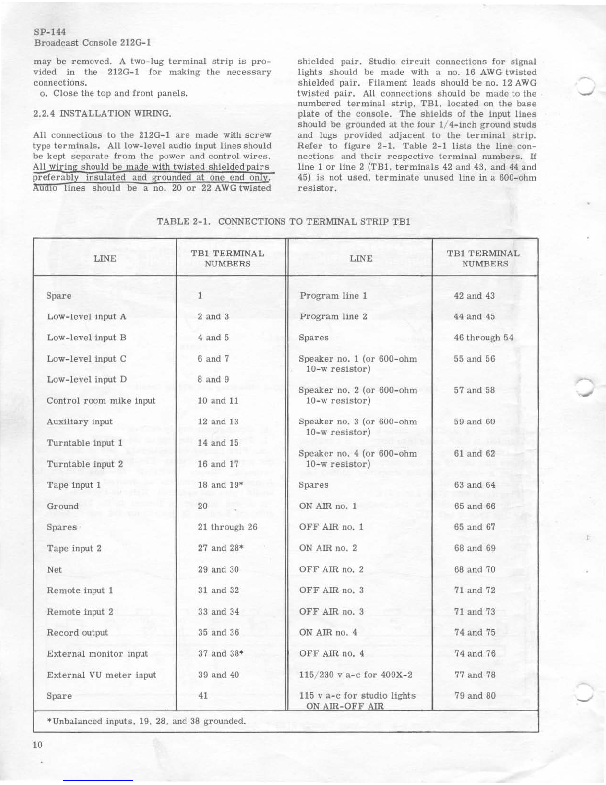
2.2.4
INSTALLATION WIRING.
All
connections
to
the
212G- l
are
made with
screw
type
terminals.
All low-level audio input
lines
should
be
kept
separa
te
from
the
power and
control
wires.
shielded
pair.
Studio
circuit
connections
for
signal
lights
should
be
made
with a no. 16
AWG
tWisted
sh
ielded
pair.
Filament
leads
should
be
no.
12
AWG
twisted
pair.
All
connections
should
be
made
to
the
numbered
terminal
strip, TBI , l
ocated
on
the
base
plate
of
the
console.
The
shields
of
the
input
lines
should
be
grounded
at
the
four
1/ 4- lnch
ground
studs
and lugs
provided
adjacent
to
the
terminal
strip.
Refer
to
figure 2-1.
Table
2- 1
lists
the
line
con-
nections
and
their
respective
terminal numbers
. U
line 1 or
line 2 (TBl.
terminals
42
and 43, and 44 and
45)
is
not
used,
terminate
unused
line
in a 600- ohm
resistor,
TABLE 2- 1. CONNECTIONS
TO
TERMINAL
STR
IP
TBI
LINE
TBI
TER
MINAL
LINE
TBI TERMINA
L
NUM
BERS NUMBERS
Spare
1
Program
line
1 42
and
43
Low-
level
input A 2 and 3
Program
line
2 44
and
45
Low-
level
input B 4 and 5
Spares
46
through
54
Low-
level
input C 6 and 7
Speaker
no. 1
(or
600-ohm
55
and 56
10-w
resistor)
Low-
level
input 0 8 and 9
Speaker
no. 2
(or
600-ohm
57 and 58
Control room
mike
inpu t
10
and
11
10-w
resistor)
Auxil
iary
input
12
and 13
Speaker
no. 3
(or
600- ohm 59 and
60
10-w
resistor)
Turntable
input 1
14
and
15
Speaker
no, 4
(or
600-ohm
61 and
62
Turntable
Input 2 16 and 17 10- w
resistor)
Tape
input 1 18 and 19·
Spares
63 and 64
Ground
20
ON
AIR no. 1
65
and
66
Spares
21
through
26
OFF
Am
no. 1 65
and
67
Tape
input 2
27
and 28·
ON
AIR no. 2
68
and 69
Net
29 and
30
OFF
AIR no. 2
68
and
70
Remote
input I
31
and
32
OFF
AIR no. 3
71
and 72
Remote
input 2
33
and 34
OFF
AIR no. 3 71 and 73
Record
out put
35
and 36
ON
AIR no. 4 74 and 75
External monitor
input
37
and 38· OFF AIR no. 4 74 and 76
External
VU
meter
input 39
and
40 115/ 230 v
a-c
for
409X-2
77
and
78
Spare
41
115 v a- c
for
studio
lights
79 and 80
ON
AIR-OFF
AIR
·Unbalanced
Inputs, 19, 28, and
38
grounded.
10
•
0'
,
}
D-
O,
0-
9
D·
7
0 0
"
10
0
"
LJ
Figure
2-3.
Jumper
Plug
Wiring
Schematic
Diagram
2.3
MODIFICATION
AND
INITIAL
ADJUSTMENTS.
2.3.1
GENERAL.
Initial
adjustments
of
Broadcast
Console
212G-l
con-
sist
of input and output
impedance
selection,
gain
level
selection
of
Program/Monitor
Amplifier
3568-1,
and
d-c
voltage
adjustment
of
Power
Supply 409X-2.
2.3.2
SELECTION
OF
IMPEDANCES.
Preamplifiers
356A-l
are
factory
wired
for
input
impedance
of
150
ohms
and oUlput
impedance
of
600
ohms.
When
Preamplifier
356A-l
Is
used
as
a
booster
amplifier,
its
input
must
be
rewired
for
250
ohms
impedance.
Refer
to
Preamplifier
356A-l
In-
struction
Book
for
rewiring
information.
Program/Monitor
Amplifier
356B-l
is
factory
wired
for
600-ohm
input and output
impedances.
For
other
desired
input
or
output
impedances.
refer
to
Program
/
Monitor
Amplifier
356B-l
Instruction
Book.
2.3.3 GAIN
ADJUSTMENT FOR
PROGRAM/
MONITOR
AMPLIFIER
356B-1.
U
Program/Monitor
AmplUier
356B-l
is
to
be
used
as a program
amplifier,
56
db
gain
is
required,
and
the
gain
selection
switch
(S301) on
the
right
front
of
the
chassis
(near
P30l)
should
be
in
the
LOW
position.
U
the
3568-1
is
to
be
used
as a monitor
amplifier.
the
switch
should
be
placed
in
the
HIGH
position
to
provide
68
db gain.
SP-144
Broadcast
Console
212G-l
2.3.4
ADJUSTMENT
OF
300 VOLTS
D-C
OUTPUT
FROM POWER
SUPPLY
409X-2.
A
screwdriver
adjustment.
R401. on
top
of
Power
Supply 409X-2
chassis
varies
d-c
output
voltage.
Adjust
R402
until
the
output
voltage
is
300
volts
d-c.
Test
points
Jl-
and
J2+
are
provided
on
the
top
of
the
chassis
to
facilitate
this
adjustment.
Jl-
Is
connected
to
B-.
J2+
to
the
B+ output.
2.3.5
INITIAL ADJUSTMENTS
FOR
USE
OF
LIMITER
AMPLIFIER
356E-1.
The
following
steps
outline
initial
adjustments
of
Limiter
Amplifier
356E-l
for a three-to-one
com-
pression
ratio:
a.
Plug
Limitier
Amplifier
356E-l
into
J8.
b.
Adjust
Power
Supply 409X-2
output
for
300
volts
d-c.
c. With no input
to
the
amplifier.
make
the
adjust-
ments
of
steps d through
f.
d.
Set
the
METER
switch
to
GR. and
adjust
the
zeroing
potentiometer,
R47.
for
a 0
reading
on
the
GR
meter.
e.
Adjust
R612
for
23.5
voltsatthetestjacks
located
on
the
356E-1.
f.
Repeat
step e after
30
minutes
warmup.
g.
Set
S601
at
average.
h.
The
GR
meter
and
amplifiers
now
are
ready
to
use.
The
GR
meter
will
read
the
level
of
the
input
signal
above
the
threshold
when
the
METER
switch
is
in
the
GR
poSition. With
the
equipment
adjusted
as
in
step
g,
the
356E-l
will
operate
according
to
steps i through
k.
1.
All
signal
below
threshold
(-44
vu)
applied
to
the
input
of
the
356E-l
will
be
amplifer
uniformly.
j.
All
signals
above
threshold
will
be
limited
at
a
three-to-one
compression
ratio.
For
every
3 YO
rise
in
input above
the
threshold
level,
the
output
level
will
increase
1
YO.
NOTE
Levels
are
specified
in
YO,
implying a com-
plex
wave,
such
as a program
waveform
with
high
peaks.
The
peaks
usually
are
assumed
to
be
about 10
db
above
the
sine
wave
peak.
When
lestingwith a sinewave
input,
it
is
normal
to
test
at a level
10 db
higher
than
normal
vu
level.
With a signal
level
10 db
higher
than
normal
level.
the
vu
meter
in
the
212G-l
will
be
pinned.
When
testing
at
higher
levels.
dis-
able
the
vu
meter
by
settfngthe
METER
switch,
S13,
to
EXT.
Zero
dbm
is a power
level
of 1
milliwatt
in 600
ohms.
k.
The
desired
amount
of
system
limiting
may
be
obtained
by
adjustment
of
Limiter
Amplifier
356E-1.
The
average
signal
level
may
be
maintained
at
thres-
hold
or
above
threshold
according
to
the
operator's
preference.
Table
2-2
gives
typical
values
of
the
11
SP-144
Broadcast
Console
212G-l
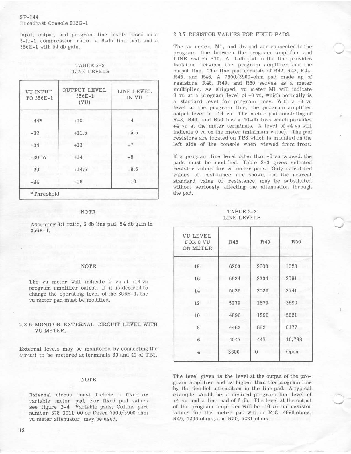
input, output, and
program
line
levels
based
on a
3-to-l
compression
ratio, a 6-db
line
pad,
and a
356E-1
with 54 db gain.
VU
INPUT
TO
356E-l
-44*
-39
-34
-30.67
-29
-24
*Threshold
TABLE
2-2
LINE LEVELS
OUTPUT
LEVEL
356E-l
(VU)
+10
+11.5
+13
+1'
+14.5
+16
NOTE
LINE
LEVEL
IN
VU
+.
+5.5
+7
+8
+8.5
+10
Assuming
3:1
ratio,
6 db
line
pad, 54 db
gain
in
356E
-1.
NOTE
The
vu
meter
will
indicate
0 vu
at
+14 vu
program
amplifier
output.
If
it
is
desired
to
change
the
operating
level
of
the
356E-1.
the
vu
meter
pad
must
be
modified,
2.
3.6
MONITOR
EXTERNAL
CIRCUIT
LEVEL
WITH
VU
METER.
External
levels
may
be
monitored
by
connecting
the
circuit
to
be
metered
at
terminals
39
and
40
of
TBI.
12
NOTE
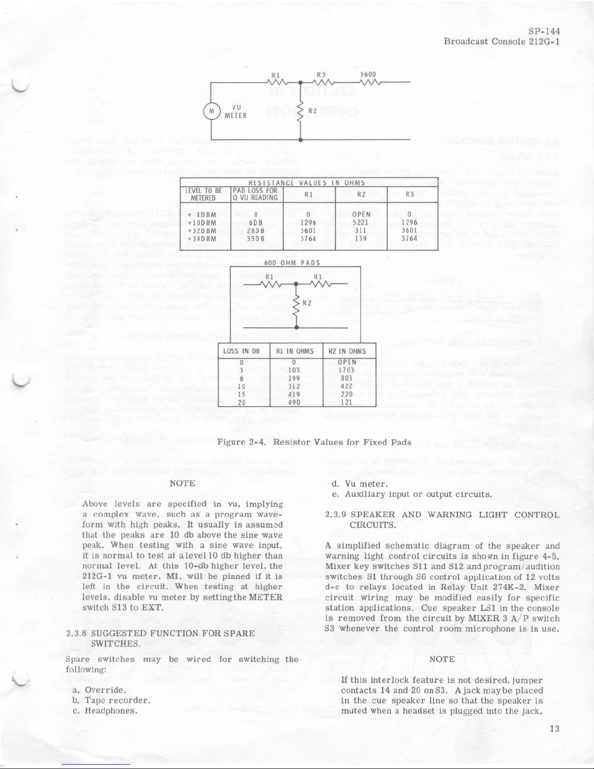
External
circuit
must
include a fixed
or
variable
meter
pad.
For
fixed pad
values
see
figure
2-4.
Variable
pads,
Collins
part
number
378 0011 00
or
Daven 7500/3900 ohm
vu
meter
attenuator,
may
be
used.
2.3.7
RESISTOR VALUES
FOR
FIXED PADS.
The
vu
meter,
Ml,
and
its
pad
are
connected
to
the
program
line
between
the
program
amplifier
and
LINE
switch
S10. A
6-db
pad in
the
line
provides
isolation
between
the
program
amplifier
and
the
output
line.
The
line
pad
consists
of
R42, R43. R44,
R45, and R46. A
7500/3900-ohm
pad
made
up
of
resistors
R48, R49, and R50
serves
as a meter
multiplier.
As
shipped,
vu
meter
Ml
will
indicate
o vu
at a program
level
of
+8
vu, which
normally
is
a
standard
level
for
program
lines.
With a
+8
vu
level
at
the
program
line,
the
program
amplifier
output
level
is
+14 vu.
The
meter
pad
consisting
of
R48. R49, and
R50
has a 10-db
loss
which
provides
+4 vu
at
the
meter
terminals.
A
level
of +4 vu will
indicate
0 vu on
the
meter
(minimum
value).
The
pad
resistors
are located
on
TB3
which
is
moonted
on
the
left
side
of
the
console
when
viewed
from
front.
If
a
program
line
level
other
than
+8
vu
is
Ilsed,
the
pads
must
be
modified.
Table
2- 3
gives
selected
resistor
values
for
vu
meter
pads.
Only
calculated
values
of
resistance
are
shown,
but
the
nearest
standard value
of
resistance
may
be
substituted
without
serious
ly
affecting
the
attenuation
through
the
pad
,
VU
LEVEL
FOR 0
VU
ON
METER
18
16
I.
12
10
8
6
•
TABLE 2-3
LINE LEVELS
R.8
R49
6203 2603
5934
2334
5626
2026
5279 1679
4896 1296
4482
882
4047
447
3600 0
R50
1620
2091
2741
3690
5221
B177
16.788
Open
The
level
given
is
the
level
at
the
output
of
the
pro-
gram
amplif
ier
and
is
higher
than
the
program
line
by
the
decibel
attenuation
in
the
line
pad. A
typical
example
would be a
desired
program line
level
of
+4
vu and a
line
pad
of 6 db.
The
level
at
the
output
of
the
program
amplifier
will
be
+10 vu
and
resistor
values
for
the
meter
pad will
be
R4B, 4896
ohms;
R49 , 1296 ohm
s;
and R50, 5221
ohms.
SP-144
Broadcast
Console
212G-l
HI
Rl
)600
LEV~_TO
8E
oYETEREQ
+
4D8M
+IOO8M
+32DBM
+39DBM
VU
M£HR
RESISTAN
~A.~
..
LOSS~~
o
VU
READING
0
608
2808
3508
600
OH
HI
,
"
"
VA
ur
IN
OHM
HI
"
Rl
0
OPEN
0
1296
H21
1296
3601
III
3601
3164
I"
3764
PADS
HI
-----'\I'v",
f"~
lOSS
IN
DB
Rl
IN
OHMS
R2
IN
OHMS
0 0
~;~~
)
IOJ
6
I"
.OJ
iO
Jl2
'"
"
'"
220
'"
..
0
l11
Figure
2-4.
Resistor
Values
lor
Fixed
Pads
NOTE
Above
levels
are
specified
in vu,
implying
a complex wave, such
as a program
wave-
form
with
high
peaks.
It
usually
is
assum~d
that
the
peaks
are
10
db
above
the
sine
wave
l>eak.
When
testing
with a
sine
wave
input,
It
is
normal
to
test
at a level
10
db
higher
than
normal
level.
At
this
IO-db
higher
level,
the
212G
-l
vu
meier,
MI,
will be
pinned
if
it
is
left in
the
circuit.
When
testing
at
higher
levels,
disable
vu
meter
by
setting
the
METER
switch
813
to
EXT.
2.3.8 SUGGESTED FUNCTION FOR
SPARE
SW
ITCHES.
Spare
switches
may
be
wired
for
switching
the
following:
a.
Override.
b.
Tape
recorder.
c. Headphones.
d,
Vu
meter.
e.
Auxiliary
input
or
output
circuits.
2,3.9
SPEAKER
AND WARNING LIGHT CONTROL
CIRCUIT
S.
A
simplified
schematic
diagram
of
the
speaker
and
warning
light
control
circuits
is
shown
in
figure
4-5.
Mixer
key
switches
S11 and S12 and
program'
audition
switches
SI
through
86
con
trol
application
of
12
volts
d-c
to
relays
located
in
Relay
Unit 274K-2.
Mixer
circuit
wiring
may
be
modified
easily for
specific
station
appli
cations.
Cue
speaker
LSI in
the
conso
le
Is
removed
from
the
circuit
by
MLXER
3 Al P
switch
83
whenever
the
control room
microphone
is
in
use.
NOTE
If
this
interlock
feature
is
not
desired,
jumper
contacts
14 and 20 on83.
Ajack
maybe
placed
in
the
cue
speaker
line
so
that
the
speaker
is
m>Jted
when a
headset
is
plugged
into
the
jack.
13
SP-144
Broadcast
Conso
le 212G
-l
SECTION III
OPERATION
3.1 CONTROL FUNCTIONS.
3.1.1 MIXER.
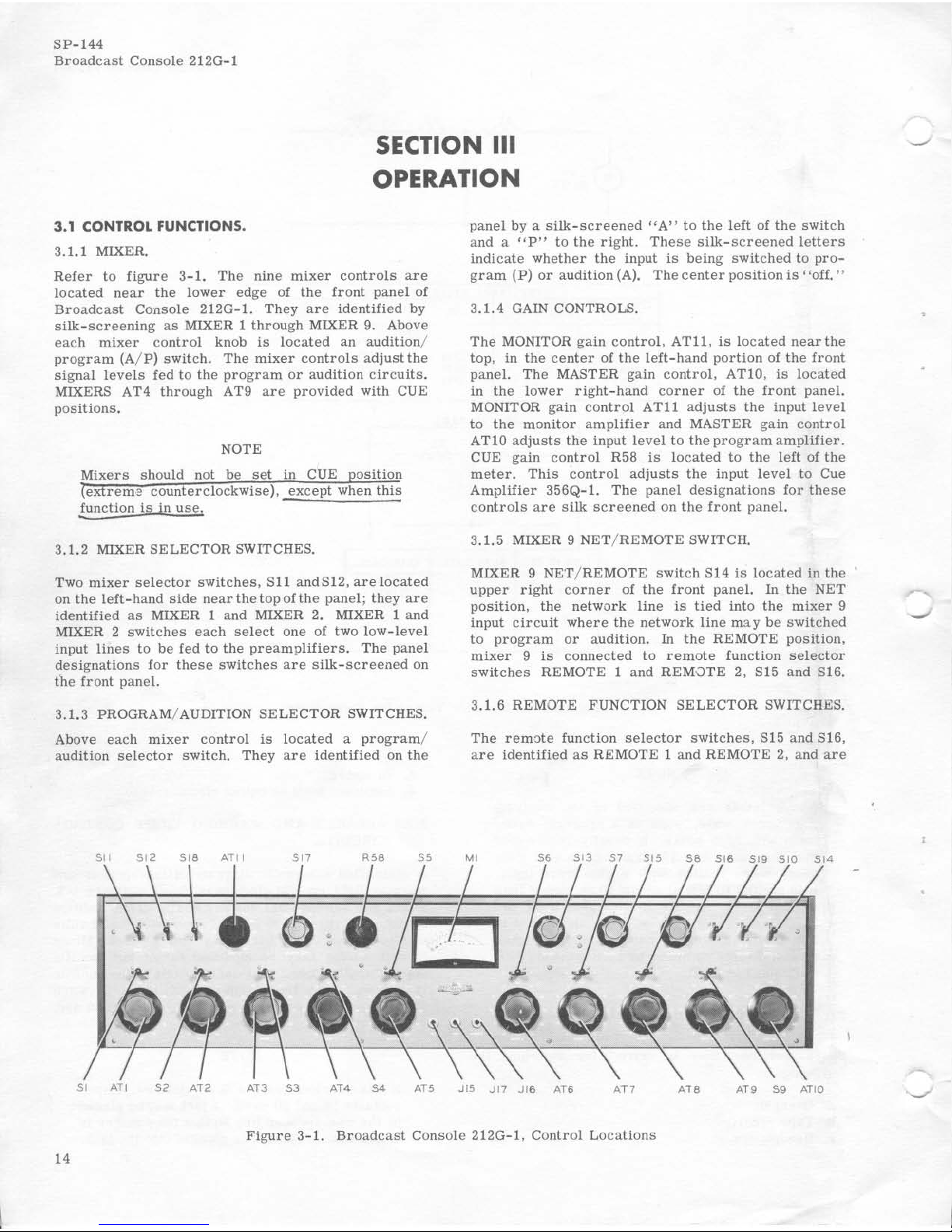
Refer
to
figure
3-1.
The
nine
mixer
contr
ols
are
located
near
the
lower
edge
of
the
front
panel
of
Broadcast
Console
212G
-1.
They
are
identified
by
silk-screening
as
MIXER 1
through
MIXER
9.
Above
each
mixer
control
knob
is
located
an
audition
/
program (A/ P)
switch.
The
mixer
controls
adjust
the
signal
levels
fed to
the
program
or
audition
circuits
.
MIXERS AT4
through
AT9
are
provided
with CUE
positions.
NOTE
!unction
is
in
use,
3.1.2 MIXER
SELECTOR SWIT CHES.
Two mixer
selector
switches.
S11
andS
12,
are
located
on
the
left
- hand
side
nearthetopofthe
panel;
they
are
identified
as
MIXER 1 and MIXER 2. MIXER 1 and
MIXER 2
switches
each
select
one
of two
low-level
input
lines
to
be fed
to
the
preamplifiers.
The
panel
designations
for
these
switches
are
silk-screened
on
the front
pane
l.
3.1. 3 PROGRAM/
AUDITION
SELECTOR SWITCHES.
Above
each
mixer
control
is
located a program
/
audition
selector
switch.
They
are
Identified
on
the
pane
l by a
silk-screened
"A"
to
the
left
of
the
switch
and a
"P"
to
the
right.
These
silk-screened
letters
indicate
whether the
input
is
being
switched
to
pro-
gram
(P)
or
audition
(A).
The center
position
is'
'off."
3.1.4
GAIN CONTROLS.
The
MONITOR
gain
control.
AT11,
is
located
near
the
top.
in
the
center
of
the
left-hand
portion
of
the
front
panel.
The
MASTER
gain
control,
ATI0,
is
located
in
the
lower
right-hand
corner
of
the
front
panel.
MONITOR gain
control ATll
adjusts
the
input
level
to
the
monitor
amplifier
and MASTER
gain
control
ATI0
adjusts
the
input
level
to
the
program
amplifier.
CUE gain
control
R58
is
located
to
the
left
of
the
meter.
This
control
adjusts
the
input
level
to
Cue
Amplifier
356Q
-1.
The
panel
designations
for
these
controls
are
silk
screened
on
the front
panel.
3.1.5
MIXER 9
NET
/ REMOTE SWITCH.
MIXER 9
NET/REMOTE
switch
S14
is
located
in
the
upper
right
corner
of
the
front
panel.
In
the
NET
position,
the
network
line
is
tied
into
the
mixer
9
input
circuit
where
the
network
line
may
be
switched
to
program
or
audition.
In
the
REMOTE
position.
mixer 9 is
connected
to
remote
function
selector
switches
REMOTE 1 and
REMOTE
2, S15
and
S1
6.
3.1.6
REMOTE FUNCTION
SELECTOR
SWITCHES.
The
rem:.te
function
selector
switches,
SIS
and S16,
are identified
as
REMOTE
1 and
REMOTE
2, and
are
Figure 3-1.
Broadcast
Console
212G- 1,
Control
Locations
14
v
located
near
the
top
, in
the
center
of
the
right-hand
p::>rtion of
the
Cront
panel.
Each
has
OFF,
MON, CUE,
and
MIX
positions.
When
both
the
audition/program
switch
and a
REMOTE
switch
are
set
at
OFF,
the
remote
line
is
terminated
in a resistive
load.
When
a
REMOTE
switch
is
in
the
MON
position,
its
remote
line
may
be
monitored
by
phones
connected
at
the
REMOTE
monitor
jack,
J16.
When one
ofthe
switches
is
In
the
CUE
position,
the
cueing
signal
from
the
m::>nitor
amplifier
may
be
fed
back
into
the
rem0te
line
for
remote
cue.
In
the
MIX
position,
the
signal
from
the
associated
rem'Jte
line
is
sent
to
mixer
9
input
when
SI4
is
in
the
REMOTE
position
.
3.1. 7
MONITOR
INPUT
SWITCH.
MONITOR
INPUT
switch
SI7
is
located
near
the
top
and
center
of
the
left
- hand
portion
of
the
front
panel.
It
has
AUD. PGM, and
EXT
positions.
The
AUDposi
-
tion
permits
the
MONITOR
level
control
and
monitor
amplifier
to
be
connected
to
the
monitor
booster
amplifier.
When
the
MONITOR
INPUT
switch
is
in
the
PGM
position,
the
program
line
is
connected
through a bridging
pad
to
the
MONITOR
level
control
and
monitor
am;Jlifier
input.
The
EXT
position
per-
mits a signal
connected
at
terminals
37
and38
of
TBI
to
be
monitored
through
the
MONITOR
level
control
and
monitor
amplifier.
3.1.8
METER
INPUT
SWITCH.
The
METER
switch.
SI3.
is
located
to
the
right
of
the
me
ter
near
the
top
of
the
front
paneL
It
has
GR, VU,
and
EXT
positions,
If
Limiter
Amplifier
356E-I
is
used,
the
GR
position
provides
indication
of
the
gain
reduction
in
decibels
above
threshold.
In
the
VU
posi-
tion,
the
vu
meter
is
connected
to
the
output
of
the
Program/Monitor
Am'Jlifier
356B-I.
In
the
EXT
posi-
tion,
the
vu
meter
is
connected
to
terminals
39
and
40 of TB1.
3
.1.9
PROGRAM SWITCH.
The
PROGRAM
switch,
SlO,
permits
switching
either
LINE 1
or
LINE 2
to
the
program
channel.
In
the
middle
position,
the
program
channel
is
terminated
in ,1
resistive
load.
3.1.10
SPARE
SWITCHES.
Two
spare
level
switches,
S18
and
S19,
are
provided
to
be
used
as
desired
in any
custom
wiring.
One
is
located
to
the
left
of
the
PROGRAM
switch
in
the
upper
right
portion
of
the
front
panel.
The
other
is
located
to
the
right
of
the
MIXER 2
switch.
Refer
to
paragraph
2.3.8
for
suggested
fUnctions
for
these
switches.
3.2 OPERATING PROCEDURES.
3.2.1
ROUTINE
OPERATION.
3.2.1.1
LOCAL
PROGRAM
ON
THE
AIR.
The
proce
-
dure
to
put a
local
program
on
the
air
is
as
follows:
a.
Select
desired
microphone
inputs
with
the
mixe
r
selector
switches,
if
applicable.
SP-144
Broadcast
Console
212G-l
b. Move
the
PROGRAM
switch,
SIO,
to
LINE I
or
LINE 2
as
desired.
c.
Set
MASTER
control,
ATIO.
to
24.
d.
Rotate
MONITOR
INPUT
switch,
SI7.
to
the
PGM
position.
e.
Move
mixer
key
switches
as
required
to
the
P
position
.
£.
Turn
up
applicable
MIXER
as
required
to
desired
level
as
indicated
on
VU
meter.
g.
Adjust
the
level
of
monitor
speakers
as
desired
by
use
of MONITOR
gain
control,
AT11.
3.2.1.2
AUDITION PROGRAM.
audition
program
is
as
follows:
The procedure
to
a.
Select
desired
microphone
inputs
with
the
mixer
selector
switches
if
applicable.
b. Move
mixer
key
switches
to
the A position.
c.
Turn
up
the
corresponding
mixer
controls.
d.
Set
the
MONITOR
INPUT
Switch,
S17,
to
AUD.
e.
The
audition
may
be
heard
over
the
monitor
speakers.
The
level
may
be
adjusted
by
means
of
the
MONITOR GAIN
control,
ATl1.
3.2.2
REMOTE
LINE
OPERATION
.
3.2.2.1
REMOTE
PROGRAM
ON
THE AIR.
The
following
procedures
are
necessary
to
put a
remote
line
on
the
air:
a. Move MIXER 9
NET/REMOTE
switch,
S14,
to
REMOTE.
b.
Set
associated
REMOTE
switch.
SIS
or
S16,
to
MIX
.
c.
Set
MIXER 9
program/audition
switch,
S9,
to
P.
d. Move PROGRAM
switch,
SIO,
to
place
program
on
desired
line.
e.
Adjust
MIXER 9,
AT9,
for
proper
leve
l.
3.2.2.2
FEED
CUE SIGNAL AND SWITCH
REMOTE
LINE
TO
ON
THE
AIR.
To
feed
cue
Signal
and
switch
remote
line
to
on
the
air,
set
up
as
previously
described
for
putting
remote
line
on
air,
except
set
REMOTE
function
switch
SIS
or
S16
to
CUE.
Thecue
signal
is
then
fed
from
the
monitor
amplifier
through
the
function
switch
to
the
remote
line.
When
the
cue
is
sent,
the
control
room
operator
switches
the
REMOTE
function
switch
SIS
or
S16
from
CUE
to
MIX,
and
the
remote
line
is
on
the
air.
3.2.2.3
RECORD
OPERATION.
For
normal
record
operation,
an
external
recorder
is
corrected
to
TBI,
connectors
35
and
36.
The
record
output
is
taken
from
the
audiqon
booster
amplifier
connected
to
JlO
when
MONITOR
INPUT
switch,
S17,
is
in
the
AUo
position.
NOTE
Disconnect
recorder
from
terminals
35
and
36
of
TBI
when
not
in
use.
15
SP-144
Broadcast
Console
212G-t
For
recording
network
program
while a
local
program
is
on the
air,
the
following
operating
procedures
may
be
used.
a. Move MIXER 9 A/ P switch, 89, to
A.
b.
Move MIXER 9 NET/ REMOTE switch, 814,
to
NET.
c. Adjust MIXER 9
for
desired
level
at
terminals
35
and 36
TBI.
3.2.2.4 TALK-BACK OPERATION USING SPEAKERS.
The following
operating
procedures
are
necessary
for
the
control
room
operator
to
listen
to a remote
line
when a
speaker
Is
used.
a. Move MIXER 9
AlP
switch, 89,
to
A.
b.
8et
MONITOR INPUT
switch,
S17, to
AUD.
c. Move MIXER 9 NET/ REMOTE
switch,
S14,
to
REMOTE.
d.
8et
applicable
REMOTE
line
switch,
S15
or
816,
to
MIX.
e. Adjust MONITOR gain
control.
ATll,
and MIXER
9, AT9,
for
desired
listening
level.
Jr.
The
following
operating
procedures
are
necessary
for
the
control
room
operator
to
talk
to
the
remote
operator:
Set
MONITOR INPUT
switch,
S17,
to
AUD.
Move MIXER 3 A/ P
switch,
S3,
to
A.
Set
Applicable
REMOTE
line
switch,
815
or
816
at
CUE. Adjust
MONITOR gain
control,
ATll, for
suitable
remote
listening
level.
/'
3.2 .2. 5 TALK-BACK OPERATION USING HEADPHONES.
The
following
operating
procedures
are
necessary
for
the
control
room
operator
to
communi-
cate
with a
remote
line
operator
when headphones
are
used.
/
a.
Plug
headphones Into REMOTE
jack,
J16.
b.
Set
MIXER 3 A/ P
switch,
S4,
to
A.
c.
Move MONITOR INPUT
switch,
S17,
to
AUD.
d. Adjust MONITOR gain
control,
ATll.
for
desired
listening
level.
e.
For
the
control
room
operator
to
talk
to
the
remote
operator,
move
the
applicable
REMOTE
line
swu.eq, S15
or
S16,
to
CUE.
For
the
control
room
operator
to
listen
to
the
remote
operator,
move
the
applicable
REMOTE
line
switch,
S15
or
S16,
to
MON.
SECTION IV
PRINCIPLES
OF
OPERATION
4
.1
GENERAL.
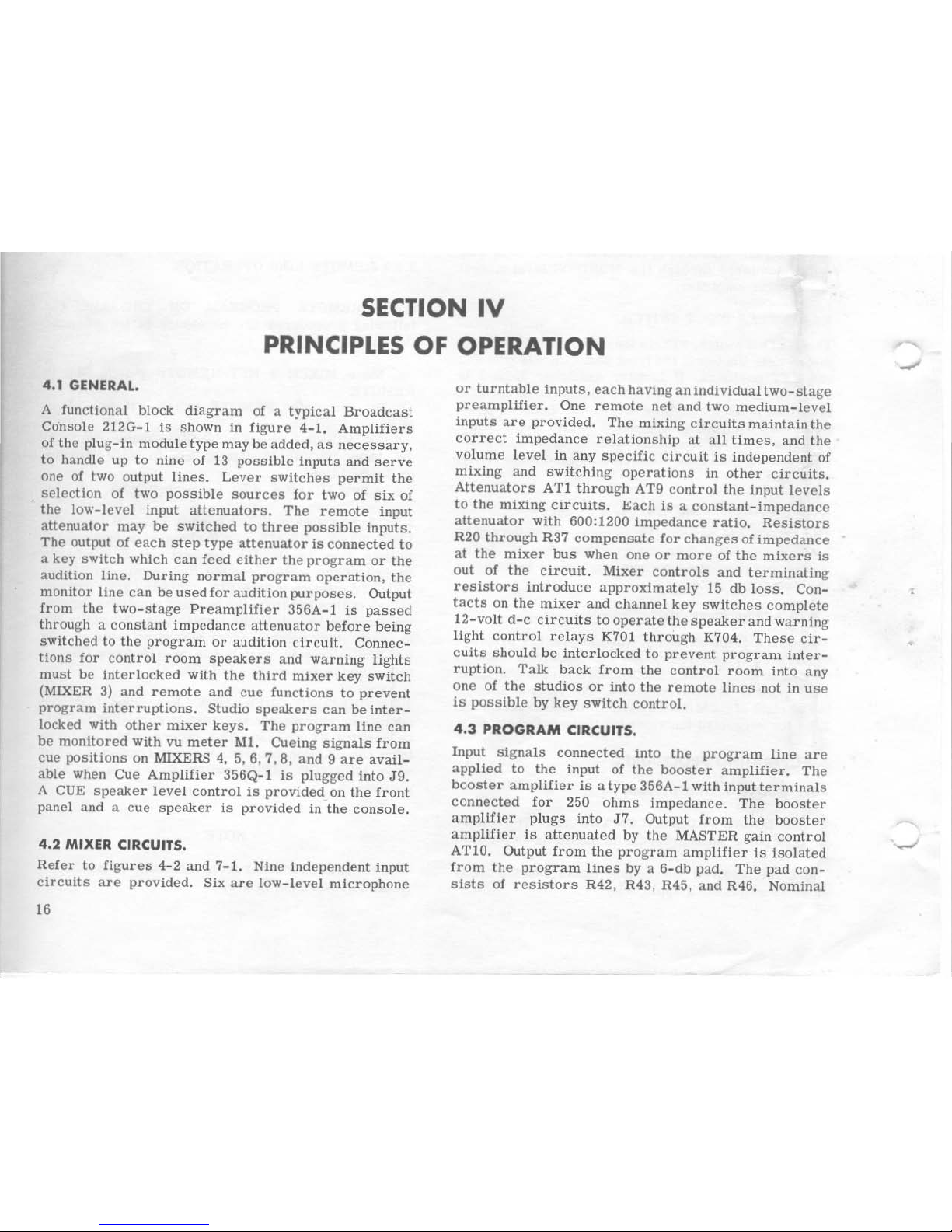
A functional block
diagram
of a
typical
Broadcast
Console
212G-l
is
shown in Cigure
4-1.
Amplifiers
of
the plug-In module
type
may
be
added,
as necessary,
to
handle
up
to
nine
of
13
possible
inputs
and
serve
one of two output
lines.
Lever
switches
permit
the
selection
of two
possible
sources
for
two of
six
of
the
low-level
Input
attenuators.
The
remote
input
attenuatOr
may
be
switched
to
three
possible
inputs.
The
output
of
each
step
type
aUenuator
is
connected
to
a key
switch
which
can
feed
either
the
program
or
the
audition
line.
During
normal
program
operation.
the
monitor
line
can
be
used
for
audition
purposes.
Output
from
the
two-stage
Preampl1f1er
356A-l
is
passed
through a constant
impedance
attenuator
before
being
switched
to
the
program
or
audition
circuit.
Connec -
tions
for
control
room
speakers
and
warning
lights
must
be
interlocked
with
the
third
mixer
key
switch
(MIXER 3) and
remote
and
cue
functions
to
prevent
program
interruptions.
Studio
speakers
can
be
inter-
locked with
other
mixer
keys.
The
program
line
can
be
monitored
with vu
meter
M1.
Cueing
Signals
from
cue
positions
on MIXERS 4,
5,6,7,8,
and 9 are
avail-
able when Cue
Amplifier
356Q-l
is
plugged into
J9.
A CUE
speaker
level
control
Is
provided
on
the
front
panel and a
cue
speaker
is
provided
in
the
console.
4.2
MIXER
CIRCUITS.
Refer
to
figures
4- 2 and 7- 1. Nine
independent
input
circuits
are
provided.
Six
are
low-level
microphone
16
or
turntable
inputs,
each
having
an
individual
two-stage
preampllIier.
One
remote
net
and
two
medium-level
inputs
are
provided.
The
mixing
Circuits
maintain
the
correct
impedance
relationship
at
ali
times,
and
the
volume
level
in
any
specific
circuit
is
independent
of
mixing
and
switching
operations
in
other
circuits.
Attenuators
AT!
through
AT9
control
the
input
levels
to
the
mixing
circuits.
Each
is a constant-impedance
attenuator
with 600:1200
impedance
ratio.
Resistors
R20
through
R37
compensate
for
changes
of
impedance
at
the
mixer
bus
when
one
or
more
of
the
mixers
is
out
of
the
circuit.
Mixer
controls
and
terminating
resistors
introduce
approximately
15
db
loss.
Con-
tacts
on
the
mixer
and
channel
key
switches
complete
12-volt
d-c
circuits
to
operate
the
speaker
and
warning
light
control
relays
K701
through
K704.
These
cir-
cuits
should
be
interlocked
to
prevent
program
inter-
ruption.
Talk
back
from
the
control
room
into
any
one
of
the
studios
or
into
the
remote
lines
not in
use
is
possible
by
key
switch
control.
4.3
PROGRAM
CIRCUITS.
Input
signals
connected
Into
the
program
line
are
applied
to
the
input
of
the
booster
amplifier.
The
booster
amplifier
is a type
356A- l with input
terminals
connected
for
250
ohms
impedance.
The
booster
amplifier
plugs
into
J7.
Output
from
the
booster
amplifier
is
attenuated
by
the
MASTER gain
control
ATIO. Output
from
the
program
amplifier
is
isolated
from
the
program
lines
by
a 6-db pad.
The
pad
con-
sists
of
resistors
R42, R43, R45, and R46. Nominal
•
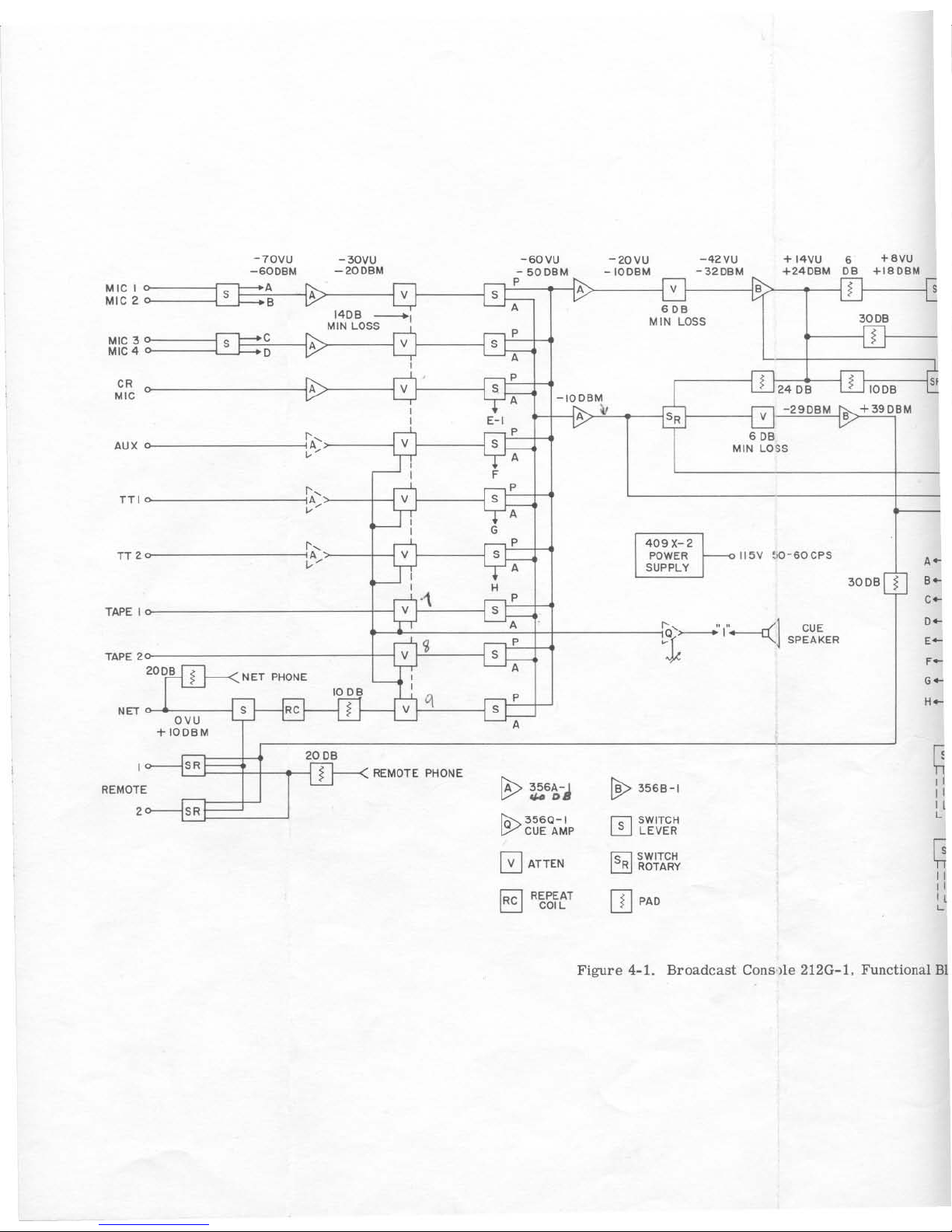
-701lU
-
30IIU
-SOIlU
-201IU
-4211U +
1411U
6
+811U
-6008M
-2008M
-
5008M
- 100BM
-:
~20BM
+2406M
OB
+180BM
MIC
1
A
P
A V
B
!
S
MIC
2
S
B
A
V S
A
60B
140B
-I
MIN
LOSS
3006
MLN
LOSS
P
!
MIC
3
C
S
A
V
S
MLC
4
0
A
P
! !
$I
CR
A V S
2408
100B
"IC
A
-10081.4
A
•
S,
V
-2
908M
B
+390BM
,-,
e,
p
60B
AUX 0
..
V
S
MIN
LOSS
.'
A
e,
p
TTlo
..
V
S
.'
A
e,
p
409X
-2
TT
20
..
V S
POWER
--011511
!,O-SOCPS
,-
v'
A
SUPPLY
H
300B
!
,-
'\
p
c-
TAPE
I
V S
A
:r'-----«:]
CO,
0-
i
P
SPEAKER
,-
V
S
F-
A
NET
PHONE
G_
q
P
H_
'"
V S
0'"
+
100BM
,
q
"
REMOTE
PHONE
REMOTE
B>
~S~-J
~
35SB-1
' I
"
"
2
"
,
[9>35S0-1
o
SWITCH
CUE
AMP
LEIIER
o ATTEN
~SWITCH
~
R
ROTARY
"
El
[]
PAO
"
REP£AT
"
COIL
,
Figure
4-1.
Broadcast Cons lle
212G-l
, FUnctional
Bl
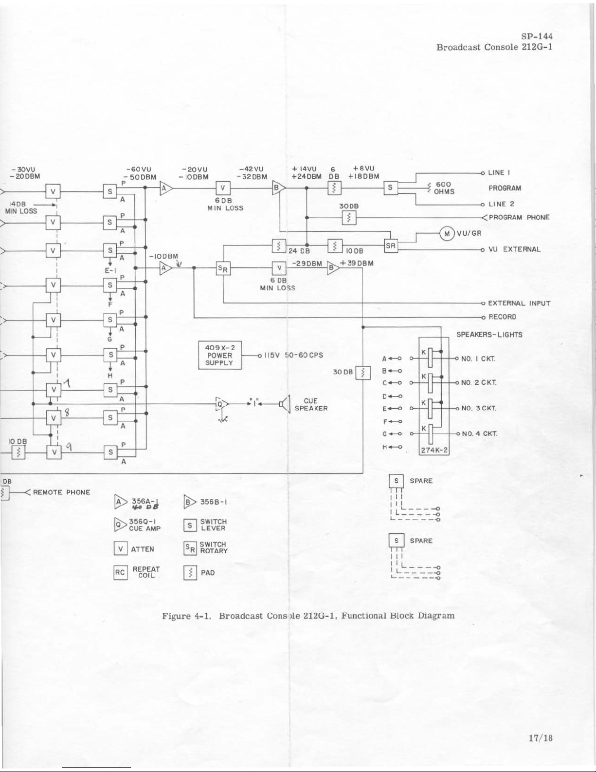
-30VU
-
60VU
-200BM
- ~OOBM
-2QVU
-IOOBM
-42VU
-320BM
SP
-144
Broadcast
Cons
ole 212G
-l
+14VU
6
}~+~.~V~U~~~::~=;~~~----O
+240BM
0IB
+180BM
LINE I
.00
S OHMS
PROGRAM
300.
L
________
~
LINE
2
V
)-----{sD=P~
I---I
A
>--------1
v
f-----I~
·
140B
_I
A
60B
M
IN
LOSS
M
IN
LOSS
v
)---------1~sQ::;=
H
1-
----1 j
1------------<
PROGRAM
PHONE
)--------~sJ:;:::tt
-IOOBM
.~--I
v
f---E~P=H
A
P
~-H
A
'~-+--1
v
)--
__
-{~St.
P
=ti
A
s
l
OB
D--<
REMOTE
PHONE
P
A
0ATTEN
REPEAT
COIL
A
>-''---.----1
s,
1------1 v
-290BM
B
+390BM
•
D.
MIN LO
SS
'--------------------------+----------------------~
EXTERNAL
INPUT
L
~~~~-----------------------~~========~===i:_~::::
RECORO
SPEAKERS-LIGHTS
409X
-2
POWER
~
II~V
~0-60C
PS
SU
PPLY
~
356B-1
r"S""l
S
WITCH
~
LEVER
Is:l
SWITCH
L:!!J
ROTARY
[]
PAD
CUE
SPEAKER
300B
~
o-l~r-l-+o
NO
. I CkT.
o-l~
'1=1
'-1-0 NO. 2 C K
T.
o-l'<IR'-I-ONO
. 3CKT.
r=-+~NO.
4
CKT
.
274K-2
~
SPARE
'"
,,,
I L'::.:.:.
:!
L
_____
-o
m
SPARE
'"
iIL----o
L
____
-o
L
_____
-o
Figure 4-1. Broadcast
Cons
lie
212G-l,
Functional
Block Dia g
ram
17/
18
 Loading...