

College Park Espire Elbow Hybrid, Espire Elbow Pro Technical Manual
Espire™ Elbow
Pro and Hybrid
technical manual

TABLE OF
CONTENTS
1 - System Overview
1.1 Introduction • • • • • • • • • • • • • • • • • • • • • • 1
1.2 Anatomy • • • • • • • • • • • • • • • • • • • • • • •2
1.3 Pre-Installation Checklist • • • • • • • • • • • • • • •2
1.4 Technical Specifications • • • • • • • • • • • • • • • • 3
2 - Batteries and Charging
2.1 The Battery • • • • • • • • • • • • • • • • • • • • • • 5
2.2 Battery Installation and Removal • • • • • • • • • • •5
2.3 LED Indicator • • • • • • • • • • • • • • • • • • • • • 6
2.4 Battery Charger • • • • • • • • • • • • • • • • • • •6
2.5 Charging the Battery • • • • • • • • • • • • • • • • • 7
3 - Inputs
3.1 Input Overview • • • • • • • • • • • • • • • • • • • •9
3.2 Input Connector Board • • • • • • • • • • • • • • • • 10
3.3 Connecting Cables
to the Input Connector Board • • • • • • • • • • • • • • • 11
3.4 Strain Relief Disc • • • • • • • • • • • • • • • • • • • 11
4 - A/C Myoelectrodes with
TruSignalTM Technology
4.1 Electrode Overview • • • • • • • • • • • • • • • • • • 13
4.2 Electrode Kits• • • • • • • • • • • • • • • • • • • • • 13
4.3 Electrode Placement • • • • • • • • • • • • • • • • •14
4.4 Myoelectric Input Labels • • • • • • • • • • • • • • •15
4.5 Electrode Installation Instructions • • • • • • • • • • • 16
5 - Axis Electronic Lock Actuator
5.1 Electronic Lock Actuator Overview • • • • • • • • • •17
5.2 Routing Cables Through the Shoulder Joint • • • • • •17
5.3 Outputs Located Above the Elbow • • • • • • • • • • • 18
6 - Measuring and Cutting Forearm
6.1 Measuring the Forearm • • • • • • • • • • • • • • • •19
6.2 Protective Foam Insert • • • • • • • • • • • • • • • •19
6.3 Cutting the Forearm to Length • • • • • • • • • • • •20

7 - Wrist Fabrication
7.1 Wrist Options Overview • • • • • • • • • • • • • • • • 21
7.2 Output Wires for Terminal Devices • • • • • • • • • •21
7.3 Quick Disconnect Wrist Installation • • • • • • • • • • 22
7.4 Motion Control Standard
Electronic Wrist Rotator Installation • • • • • • • • • • • •22
7.5 Ottobock 10S17 Electronic
Wrist Rotator Installation • • • • • • • • • • • • • • • • • 23
8 - The Lamination Collar and Clamp Ring
8.1 Orientation of the Lamination Collar
and Clamp Ring • • • • • • • • • • • • • • • • • • • • • •25
8.2 Internal-External Rotation • • • • • • • • • • • • • •25
8.3 Attaching the Lamination Collar
to the Elbow • • • • • • • • • • • • • • • • • • • • • • •26
8.4 Determining Proper
Orientation on Test Socket • • • • • • • • • • • • • • • •26
8.5 Final Adjustment with the User • • • • • • • • • • • •26
9 - Setting Up Counterbalance
for Hybrid Version
9.1 Counter Balance Overview • • • • • • • • • • • • • •27
9.2 Counter Balance Adjustment • • • • • • • • • • • • •27
10 - Maintenance and Troubleshooting
10.1 Troubleshooting • • • • • • • • • • • • • • • • • • •29
11 - Intended Use and Safety
11.1 Intended Use • • • • • • • • • • • • • • • • • • • • • 31
11.2 Safety • • • • • • • • • • • • • • • • • • • • • • • • 31

SECTION 1 SYSTEM OVERVIEW
Federal Law restricts that the Espire Elbow system is to be purchased,
configured and fit only by a board-certified prosthetist, licensed by the
state in which they practice. This device is intended for use in accordance
with the information contained in this document. Instruct the patient on
proper use of this device before transferring device to patient.
Intended Use Statement:
The Espire Elbow is to be used exclusively for external prosthetic fittings
of the upper limbs. The Espire Elbow processes the end-user’s input
signals to activate and control powered elbow movement.
1.1 INTRODUCTION
Thank you for purchasing the Espire Elbow system from College Park
Industries. The following pages will cover everything you need to know
about this system from setup to operation. If you have any questions,
concerns or comments, please contact our Technical Service team at
800 728 7950 (US/Canada), (+1) 586 294 7950 (International).
In the following document you will find information on everything from
fabrication to maintenance and care of the Espire Elbow system. Read
these instructions carefully and educate the end-user on all functions
of this product before final delivery. Espire is a tool designed to make
the lives of prosthetists and transhumeral (or above elbow) amputees
successful and productive.
The Espire Elbow is a state-of-the-art, internally powered, myoelectric
elbow prosthesis. Espire Pro uses electrical signals from muscles to
proportionally control a powered elbow and terminal devices, whereas
the Espire Hybrid uses electrical signals from muscles to control terminal
devices only. College Park does not recommend that the device contain
more than 3 degrees of freedom; the clinician should evaluate according
to the combination of terminal devices that are required by the patient.
The system’s versatility also allows many other control schemes such as
switches, linear transducers, pattern recognition systems, etc. Signals
from these inputs are processed by Espire’s internal microprocessor unit
and then sent to the respective devices.
1 | Espire Elbow Technical Manual
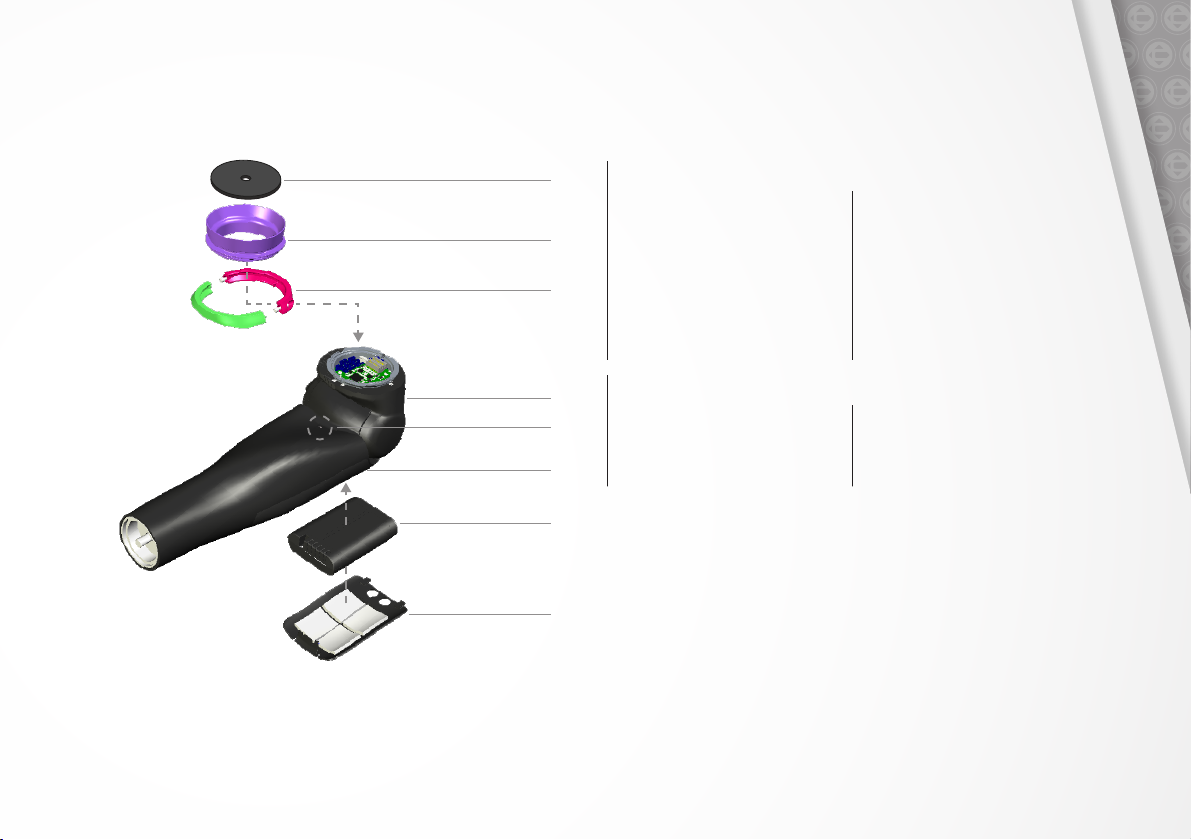
1.2 ANATOMY 1.3 PREINSTALLATION CHECKLIST
What’s in the box:
Sealing Cover
Lamination Collar
Lamination Clamp Assembly
(Clamp Ring)
Drive Unit
LED Indicator
Forearm
Battery
Battery Cover
Hardware
▪ Espire Elbow
▪ iPad (optional after first
elbow purchase)
▪ Lamination Collar and
Clamp Ring
▪ Strain Relief Disc
Instruction Manuals
▪ Espire Elbow Quick Setup Guide
▪ Espire Elbow Technical Manual
▪ Espire Elbow User Manual
▪ 2 Lithium-Ion Batteries
▪ Battery Charger with Adapter
▪ Selected Input Accessories
(electrode kits, linear
transducer, etc)
▪ Selected Terminal Devices
(hand, wrist, etc)
▪ Espire Elbow Fabrication
Instructions
▪ Espire Elbow Hub App Instructions
Espire Elbow Technical Manual | 2
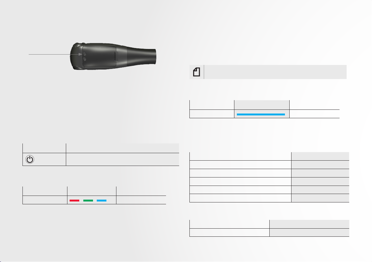
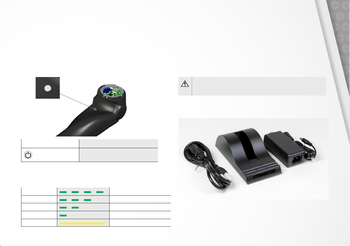
Powering on the Espire Elbow:
Power Button
Pairing Espire to iPad
The Espire Elbow will emit a Bluetooth signal for 2 minutes after it is
powered on, during which time it can be paired with the Espire Elbow
iPad application. Once a Bluetooth connection is established, the LED
indicator will display a blue light during the pairing.
Note: For information on use with the iPad, refer to the Espire Elbow
Hub App Instructions - Pro and Hybrid.
The power button is located on the underside of the Espire Elbow. To
turn the device on or o, press and hold the power button for 4 seconds.
When the device is powered on or o, a multi-colored light on the LED
indicator will flash for 1 second.
The system may also be configured with an external switch for turning
the Espire Elbow on and o. Pressing the switch will also turn the system
on or o.
Feature Description
Power Butto n Press and hold for 4 seconds to turn Espire ON or OFF
Elbow LED Indication - Power
Color Indicator Status
Multi-Color Blink Power ON or OFF
3 | Espire Elbow Technical Manual
Elbow LED Indication - Bluetooth
Color Indicator Status
Blue Solid Bluetooth connection
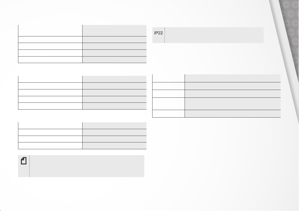
1.4 TECHNICAL SPECIFICATIONS
SPECIFICATIONS
Weight Limit 25 lb (11.3 kg)
Maximum Lifting Force 10 ft-lb (13.6 N-m)
Flexion Angle (preset control) -5 - 135⁰
Speed (preset control) 135⁰/se c
Max Cable Length (A/C Electrode Cable) 24” (609 mm)
Mode of Operation Continuous
CONNECTIONS
Inputs 12
Outputs 4
DEVICE OPERATION – INTERNALLY POWERED
Battery (removable) Smart Li-Ion
10.8 V, 3,000 mAh, 32 Wl
Time to full charge 3.5 hours
Voltage (elbow) 11.1 V nominal
Voltage (hand) 7.4 V regulated
Charger 100-250 VAC, 24 V, 2.5A DC
IP Rating
Protected from touch by fingers and objects greater than 12
millimeters. Protected from water spray less than 15 degrees
from vertical.
List of Currently Approved Terminal Devices
(contact CPI regarding any devices not listed here)
WIRELESS
Connection Bluetooth 4.2
Maximum Speed 24 Mbps
Maximum Range 330 ft (10 m)
Operating Frequency 2.402 - 2.480 GHz
BLE Power 4dBm
ENVIRONMENTAL USE CONDITIONS
Charging (temperature) 32F to 113F (0C to +45C)
Operating (temperature) 41F to 104F (5C to 40C)
Storage & Transport (temperature) -4F to 140F (-20C to +60C) *
Operating Relative Humidity 15% to 90%
Note: If storing device above or below operating temperature, allow the
device to return to within operating temperature range before using.
The device must be brought up to the operating temperature. Allow the
device to sit for 15 minutes.
Manufacturer Product
Hy5 Hy5 hand
Motion Control Electronic Wrist Rotator, ETD2
Ossur iLimb hands
Ottobock bebionic hand, Electric Greifer, Electronic Wrist Rotator,
SensorHand Speed
Taska Prosthetics Taska hand
Espire Elbow Technical Manual | 4
SECTION 2
BATTERIES AND CHARGING
2.1 THE BATTERY
The Espire Elbow system is supplied with two removable lithium-ion
batteries. This battery supplies 3000 mAh at 11.1 volts for the elbow and
7.4 volts for the terminal device(s). It is advised to rotate use of these
batteries, keeping one as a spare for backup power. For most users, one
battery will last an entire day*, depending on the prosthetic components,
condition of the battery and the frequency of use.
The batteries are shipped with a partial-charge (up to 30%). We
recommend charging both batteries to 100% upon receiving the Espire
Elbow system.
*based on average use during an 8-hour period
Caution: Use only the College Park Industries manufactured Espire
Elbow battery pack and the provided battery charger with the Espire
Elbow system. Always follow the manufacturer’s instructions for proper
removal of and replacement of battery pack.
Note: If storing the Espire Elbow for an extended period without using,
remove battery pack from the elbow before storage.
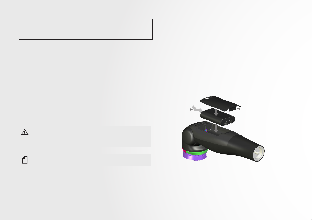
2.2 BATTERY INSTALLATION AND REMOVAL
Batteries can be removed and replaced as necessary. To remove the
battery, simply push the battery cover clip and gently lift it o the
elbow. Use the pull tab to remove the battery.
Installing a battery is the reverse process. Insert the battery into the
elbow, ensuring that the pull tab is accessible for future removal. Then,
apply the battery cover. The battery cover clip will “click” into place
when seated.
Elbow – Bottom View
Pull Tab
Battery Cover Clip
5 | Espire Elbow Technical Manual
2.3 LED INDICATOR
2.4 BATTERY CHARGER
The Espire Elbow is equipped with a state-of-charge indicator. This
indicator tells the user how much life is left in their current battery. The
Espire must be powered on to use this feature.
Press the power button for one second to activate the LED indicator light
on the forearm. The number of blinks indicates the state of the charge.
Feature Description
Power Button
Press and hold for 1 second to indicate
the battery status
Elbow LED Indications – Battery
Color Indicator Battery Status
4 Green Blinks 100% Charged
3 Green Blinks Less Than 75%
2 Green Blinks Less Than 50%
1 Green Blink Less Than 25%
Yellow Solid Critically Low - Charge Battery
Espire Elbow systems are supplied with a Smart Charger for the
lithium-ion battery. The charger is recommended for daily use and will
assure that the battery will receive a full charge and provide maximum
running time. There are two charger types (single-bay or dual-bay) and
three power adapter options (US, UK, or European) to match the needs
of dierent regions. There is also a car charger available.
Caution: Using a dierent A/C adapter than the one provided with
your battery charger may cause damage to the Espire battery or
battery charger.
Single-Bay Charger
(Also available in Dual-Bay)
Espire Elbow Technical Manual | 6
2.5 CHARGING THE BATTERY
Charging the Espire Elbow Battery
1. Place the charger on a flat, level sur face away from sources of heat and moisture.
Plug the A /C connector from the power supply into the back of the charger and
connect the power supply to the main A/C supply using the cable supplied.
2. If the battery you wish to charge is inside of the Espire Elbow, it must first be
removed from the batter y bay. Remove the battery cover via clip and remove the
batter y by using the pull tab.
3. Place the battery into the batter y bay ensuring that the 5-way connector is fully
seated. The LEDs in the status window will provide status information and the
charger will automatically begin charging.
Recharge time from empty is approximately 3.5 hours.
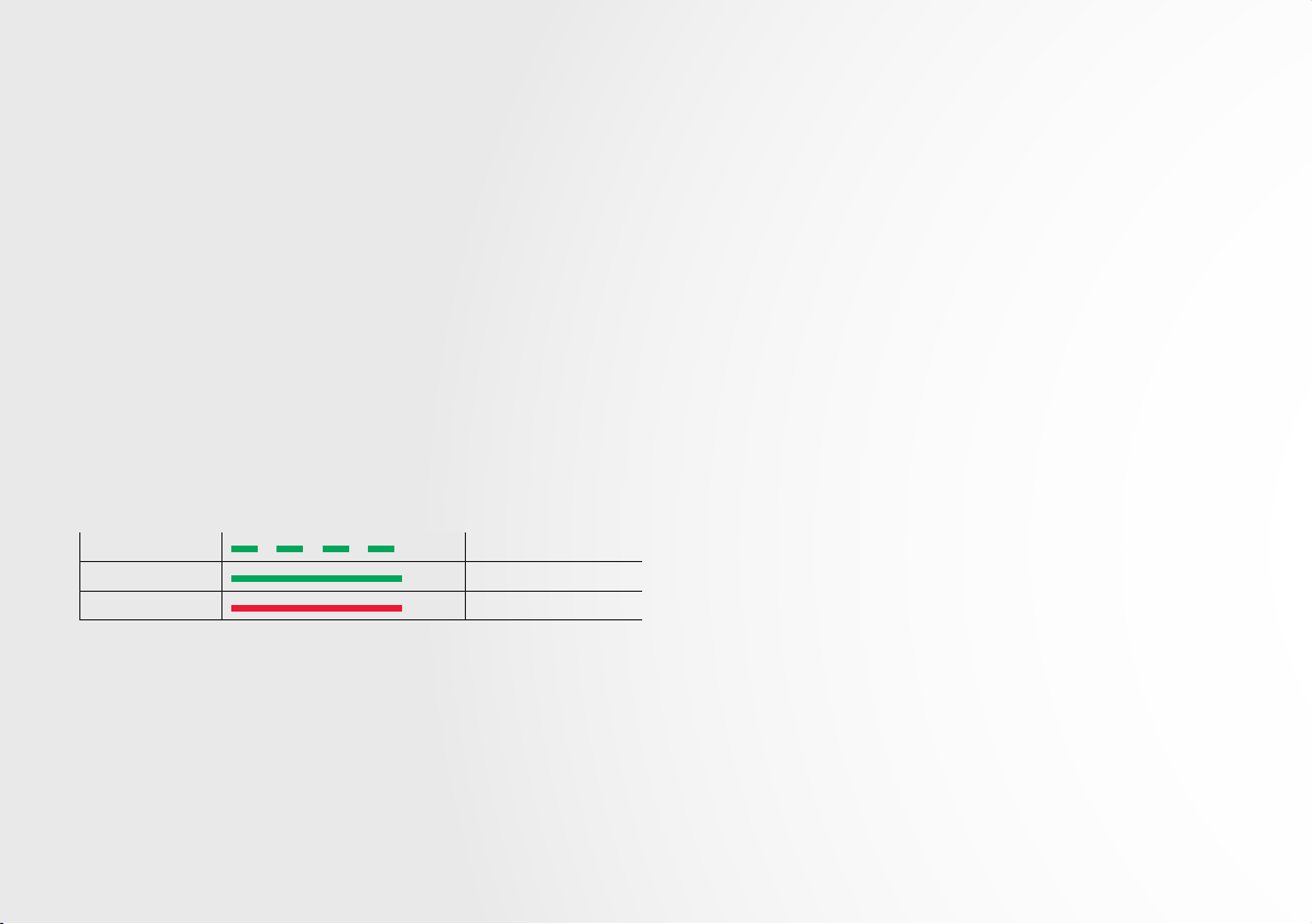
Battery Charger LED Indications
Color Indicator Battery Status
Green Blinking Charging
Green Solid Fully Charged
Red Solid Error
7 | Espire Elbow Technical Manual

Espire Elbow Technical Manual | 8

SECTION 3 INPUTS
3.1 INPUT OVERVIEW
The Espire Elbow is compatible with many types of inputs, which will be
installed with the configuration specified at the time of ordering.
List of Supported Inputs
Manufactured by CPI:
▪ A/C Electrodes (see section 4)
▪ Linear Transducers
▪ Touch Pads
Other Manufacturers:
Note: Input components from other manufacturers will require a unique
wire harness and must be installed and tested by CPI prior to delivery.
▪ D/C Cased Electrodes
▪ Switches (Single-State, Dual-State, Bump, etc)
▪ Remote Power Switches
Items Not Listed: Contact College Park for customized cable and
adapter options.
Other Inputs:
TMR
▪ Can utilize either A/C or D/C electrodes
CoApt Pattern Recognition
▪ Compatible with CoApt version 2.0
▪ CoApt controller used in place of input connector board
▪ Utilizes A/C electrodes:
- This setup requires up to 16 electrodes
- Unique cabling to fit their scheme
9 | Espire Elbow Technical Manual
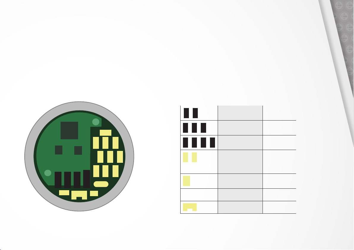
3.2 INPUT CONNECTOR BOARD
Every Espire Elbow will be shipped with the configuration specified at the
time of ordering. Dummy plugs will be placed into unused receptacles.
The included overlay displays the function of each input. Your current
setup can be viewed in the app under the diagnostics tab.
The table below lists the location, the type of input that can be used, and
its setup type.
Input Connector Board - Top View
7
6
A B C D
10
8
5
4
9
1
23
Board Location Input Option Setup Type
D
A +
A
+ B +
A
+ B + C +
1
9
-
10
D
A/C Myo 1-site or 2-sites
A/C Myo w/ TMR 4-sites
A/C Myo w/ TMR 6-sites
D
D/C Myo
Linear Transducer
Touch Pads
Switches
Remote Power Switch 1 input
Any combination
up to 9 inputs
12
11
Substitute with
CoApt controller
CoApt 8-sites
Auxillary Port
Espire Elbow Technical Manual | 10
3.3 CONNECTING CABLES
TO THE INPUT BOARD
When attaching cables, note the proper orientation. The connectors
are “keyed” or asymmetrical to assure proper alignment. The connector
should plug in easily and is held in place with friction.
When removing cables, pull close to the connector to avoid pulling on the
wires. Wires that become loose could cause intermittent operation.
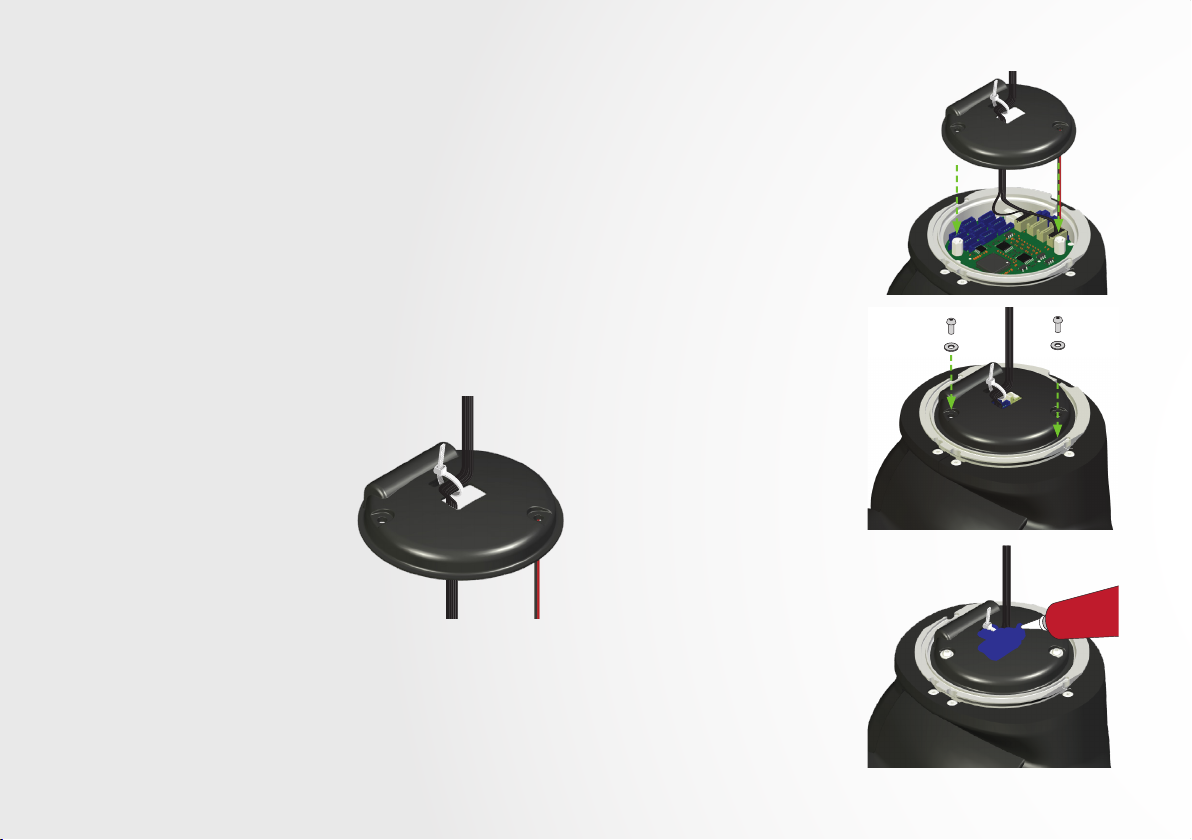
3.4 STRAIN RELIEF DISC
The strain relief disc prevents accidental disconnection of the input
wires and acts as a seal to prevent moisture and dirt from entering from
entering the area with the receptacles.
1. Thread the input wires through
the center hole of the disc, then
connect the wires to the board.
Apply silicone grease to the plug
connectors before inserting into the
board (see section 3.3).
2. Fasten the wires to the strain relief
disc using the provided zip-tie. This
is necessary to prevent accidental
wire disconnection.
Sealing the Input Board
3. Apply a small amount of silicone
grease at the perimeter seal
between the disc and the ring.
4. Line up the fastener holes on the
disc to the mounting threads on the
input board, then gently press the
disc to the board.
5. Use (2) M2 x 5mm fasteners and
washers to secure the disc to the
input board. A 1.3 mm Allen wrench
has been provided to tighten the
fasteners finger-snug
(2 in-lb / 0.23 N-m).
6. It is important to seal the holes
where the wires pass through
the strain relief disc before final
assembly of the socket. Apply RTV
silicone over the strain relief hole,
zip-tie hole, and wires.
E
N
V
O
C
T
I
L
I
R
S
11 | Espire Elbow Technical Manual
 Loading...