

Collcomm NCS-C151 Instruction Manual

NCS-C151
INSTRUCTION MANUAL
Rev B
Collcomm Inc.
d.b.a. NCS
Shipping Address
2310 Pendley Road
Cumming, Georgia 30041
Mailing Address
1595 Peachtree Parkway
Suite 204-123
Cumming, Georgia 30041
Toll Free Tel. & Fax : 888- 883-5788
Email : support@ncsradio.com
Web Site: www.collcomminc.com
collcomm inc
NCS-C151 Manual Rev B Page 2
Revision History
Rev
Description
Date
App’d
0
Initial Release
07/14/14
JFP
A
Corrected for Trunking Radio on RAD1;
Added Tx Audio Levels; corrected DC
wire size & current consumption
1/7/16
JFP
B
Removed 125mVpp AGC Reference
3/27/17
JFP
Model No.: NCS-C151
Serial No. : ___________________________
Accessory Kit
Item # Description QTY
1 10’ DC Power Cable (NCS-410-PSP-10) 1
2 Mounting Feet 4
3 Mounting Bracket Kit 1

NCS-C151 Manual Rev B Page 3
Table of Contents
Section Description Page
1.0 Introduction 4
2.0 Safety Information 4
3.0 Front Panel Controls 5
4.0 Radio Requirements 5
4.1 Receive Audio 5
4.2 Transmit Audio 5
4.3 PTT 5
5.0 Power Supply 6
5.1 Power Requirements 6
5.2 Power Connection 6
5.3 Polarity 6
5.4 Fusing 6
6.0 Opening Unit to Perform Adjustments 7
7.0 Internal Setup and Adjustments 8
8.0 Trunking Delay Operation 10
9.0 Radio Interface Cables 11
9.1 Radio Interface and AUX Jack Pin-outs 12
10.0 Troubleshooting 13
11.0 Contacting NCS 14
12.0 C151 Specifications 15
13.0 Warranty 16
NCS-C151 Manual Rev B Page 4
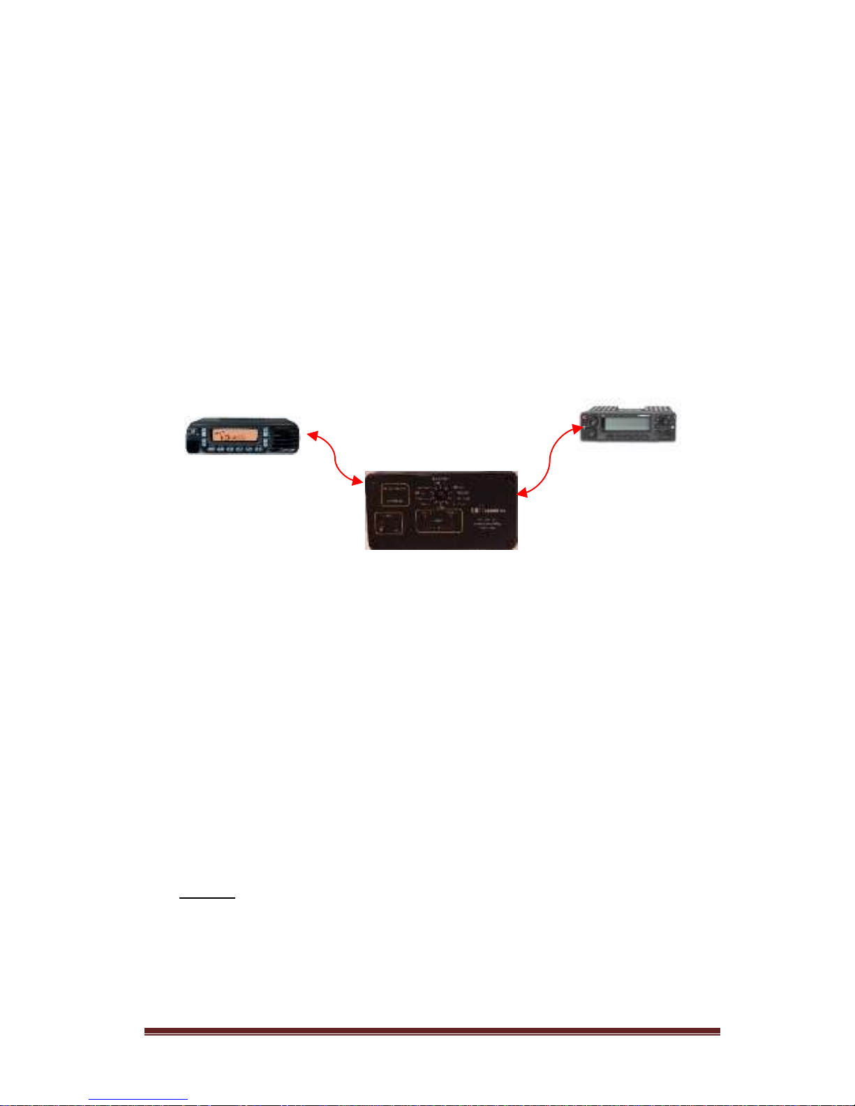
1.0 Introduction
The C151 provides a method of connecting two radios together for purposes of
in-band or cross-band repeating.
Almost any radio can be used with the C151. Either VOX or COR can be used
as a “busy” signal and COR polarity can be either + or -. Receive audio levels
do not need adjustment due to built-in AGC circuits for both radios. Transmit
audio levels can be adjusted independently for each radio.
A separate record output is provided that records audio transmitted on either
radio. A record control output is included to control an external recorder.
Typical Application
Conventional Radio – RAD 2 Trunking Radio – RAD 1
2.0 Safety Information
The C151 is an electrical device requiring appropriate safety measures during
installation and operation. The following safety precautions should be
observed:
When connecting the unit to a DC power source, a minimum wire size of
24 AWG should be used. When using in a mobile environment,
automotive grade wire should be used.
Do not route cables or wires through areas that may cause the insulation
to be worn resulting in shorting of the wires to ground or to each other.
Do not attempt to operate this equipment while driving a vehicle. For
safety, pull over to the side of the road when making adjustments.
NEVER connect this device to an AC voltage source. Death or injury could
occur and/or the unit can be badly damaged. Connect this device only to a
DC power source with a voltage output of 9-16 volts and a current
capability of at least 100 ma.
NCS-C151 Manual Rev B Page 5
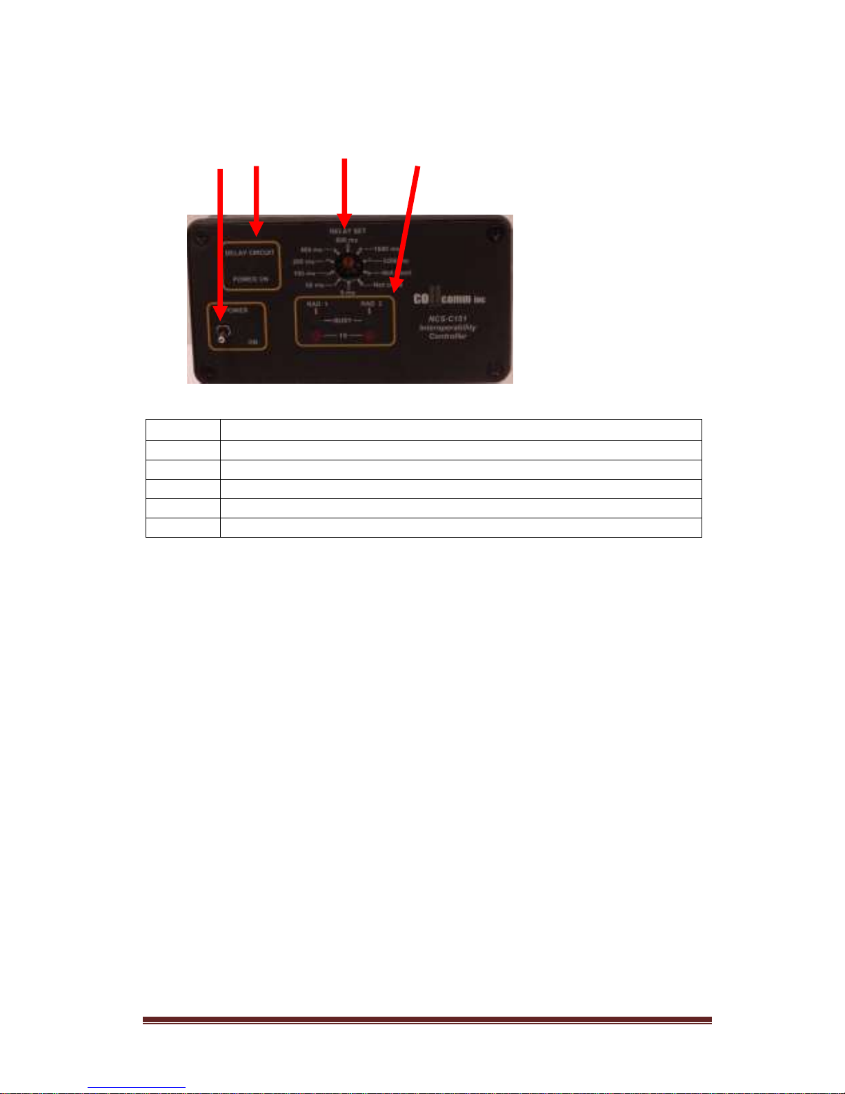
3.0 Front Panel Controls
4.0 Radio Requirements
4.1 Receive Audio
Receive Audio input levels from the radio are not critical. The Busy lights
activate (when using VOX) at approximately 150mV. Receive audio input
levels are automatically adjusted by an AGC circuit. The AGC circuit for
each radio will produce an output of 1.25Vpp.
4.2 Transmit Audio
Transmit audio levels are separately adjustable for each radio and
sufficient gain is available to drive nearly any radio.
4.3 PTT
PTT is via an Open-Drain output. This signal pulls the PTT line of the
radio low and will key any radio with a low-true PTT requirement.
Maximum switching capacity of the PTT output is 100V, 1.5A DC.
Item
Description
1
Power Switch with Green Indicator
2
Delay Circuit Power Indicator
3
Audio Delay Set Pot
4
Radio 1 & 2 Indicators: Red = Transmit and Green = Receive
1 2 3 4
 Loading...