

Page 1
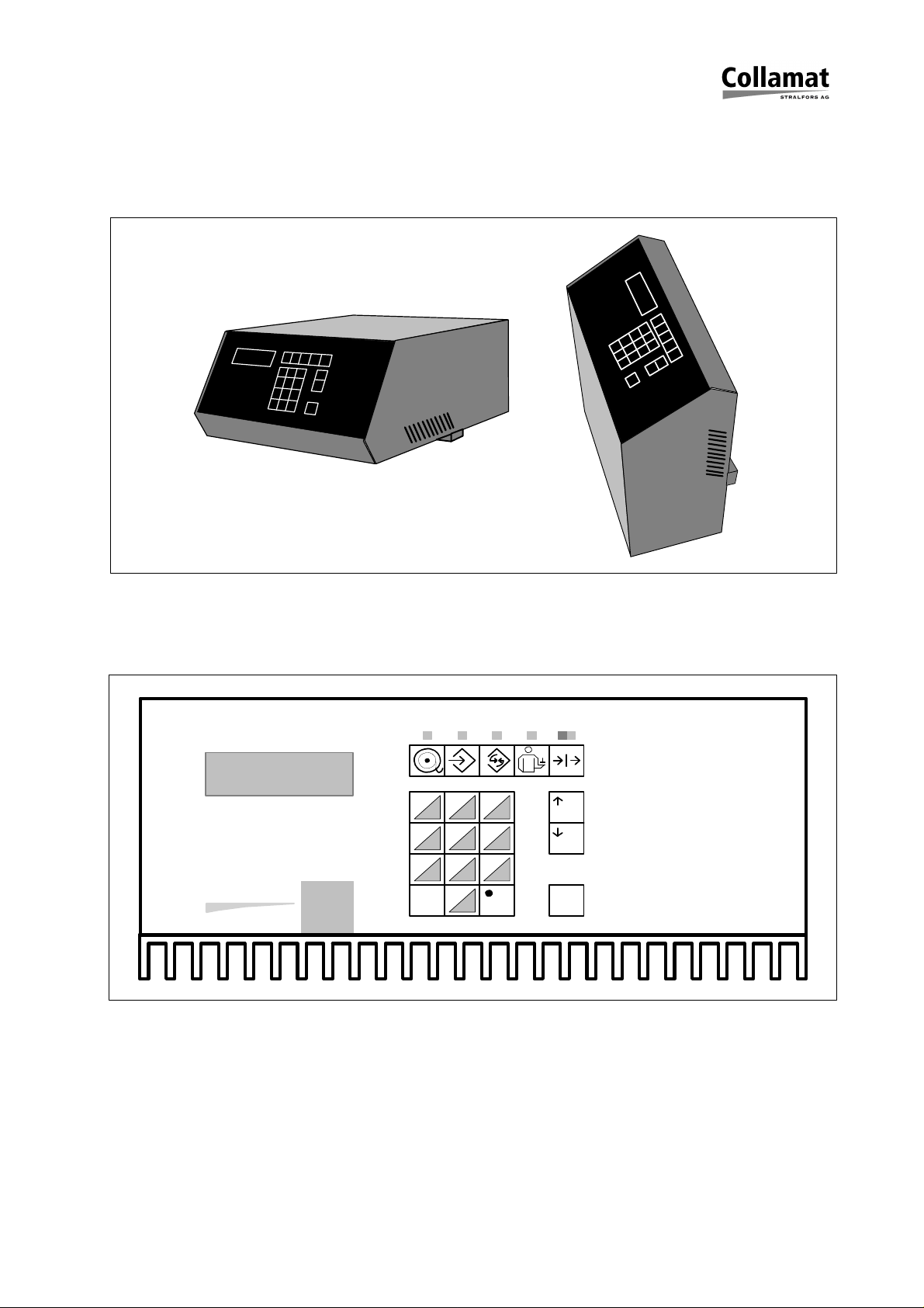
The Monitor Collamat® 8600 / 9100
Monitor installation
A B
Frontpanel
COLLAMAT
1 2 3
4 5 6
7 8 9
0
ESC ENTER
C91TR04E.SAM 10.09.98 WM Page 1 / 26
Page 2
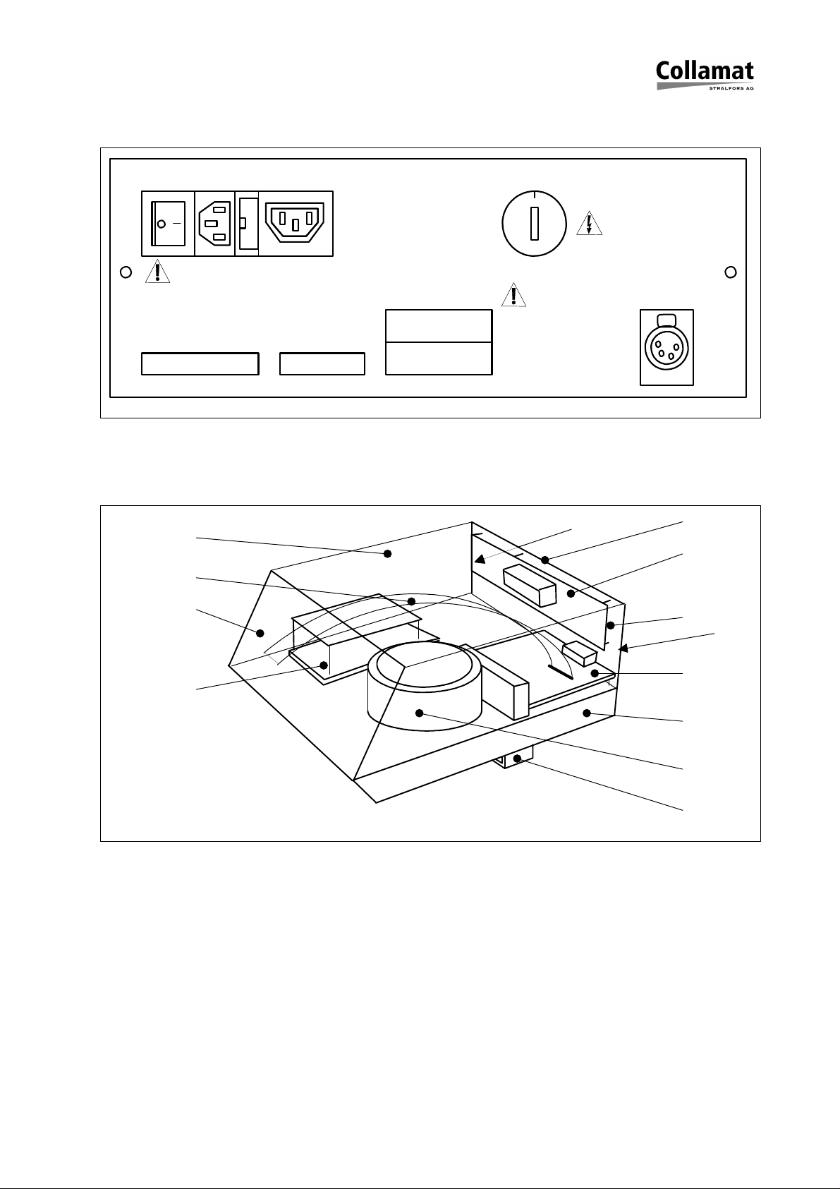
Rear Panel
CAUTION
FOR CONTINUED PROTECTION
AGAINST FIRE, REPLACE ONLY
WITH FUSE OF THE SPECIFIED
VOLTAGE AND CURRENT RATINGS
DISPENSER
GSC
CONTROL SIGNALS
Assembly parts of the monitor
VOLTAGE SELECTOR
CAUTION
DO NOT DISCONNECT ANY
PLUGS UNDER POWER ON
ACHTUNG
BEI EINGESCHALTETEM
GERÄT KEIN STECKER
HERAUSZIEHEN
ATTENTION
NE DEBRANCHER
AUCUNES FICHES SOUS
TENSION
WARNING
BEFORE OPENING, UNPLUG
POWER CORD, DANGEROUS
VOLTAGES INSIDE, SEE MANUAL
FOR SAFETY INSTRUCTIONS
MOTOR
PUSH
1
11
5
6
2
3
7
11
8
4
9
10
12
C91TR04E.SAM 10.09.98 WM Page 2 / 26
Page 3
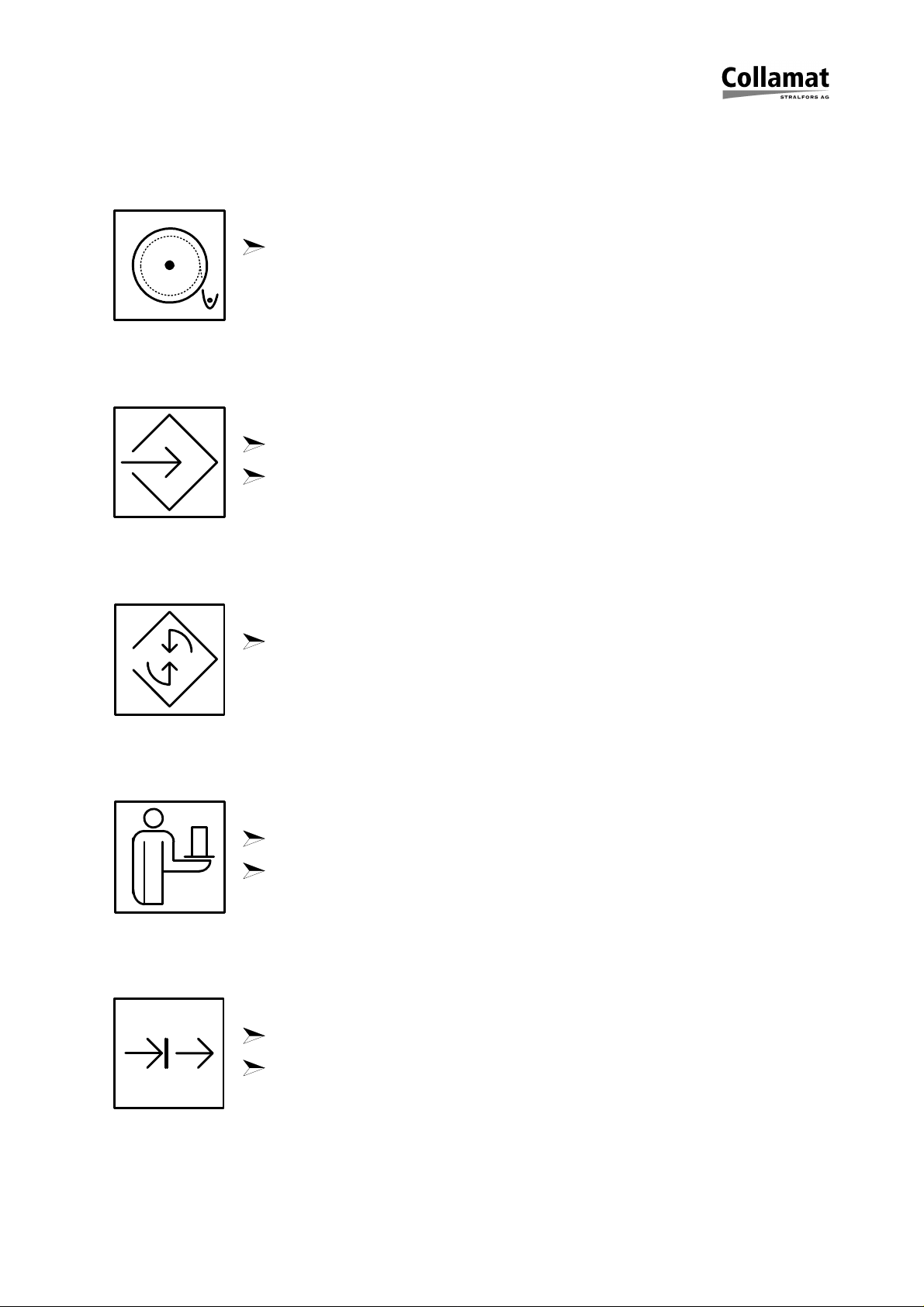
The keyboard of C8600 / C9100
Menu Labelling
Functions which are used during the normal
labelling mode.
Menu Programming
All settings for labelling
Handling of labelling Programs
Menu Configuration
All system parameters which normally are
set once.
Menu service functions
Common working data
Test functions
Key Run / Stop
Stop function is always active
Run function is temporary blocked
C91TR04E.SAM 10.09.98 WM Page 3 / 26
Page 4
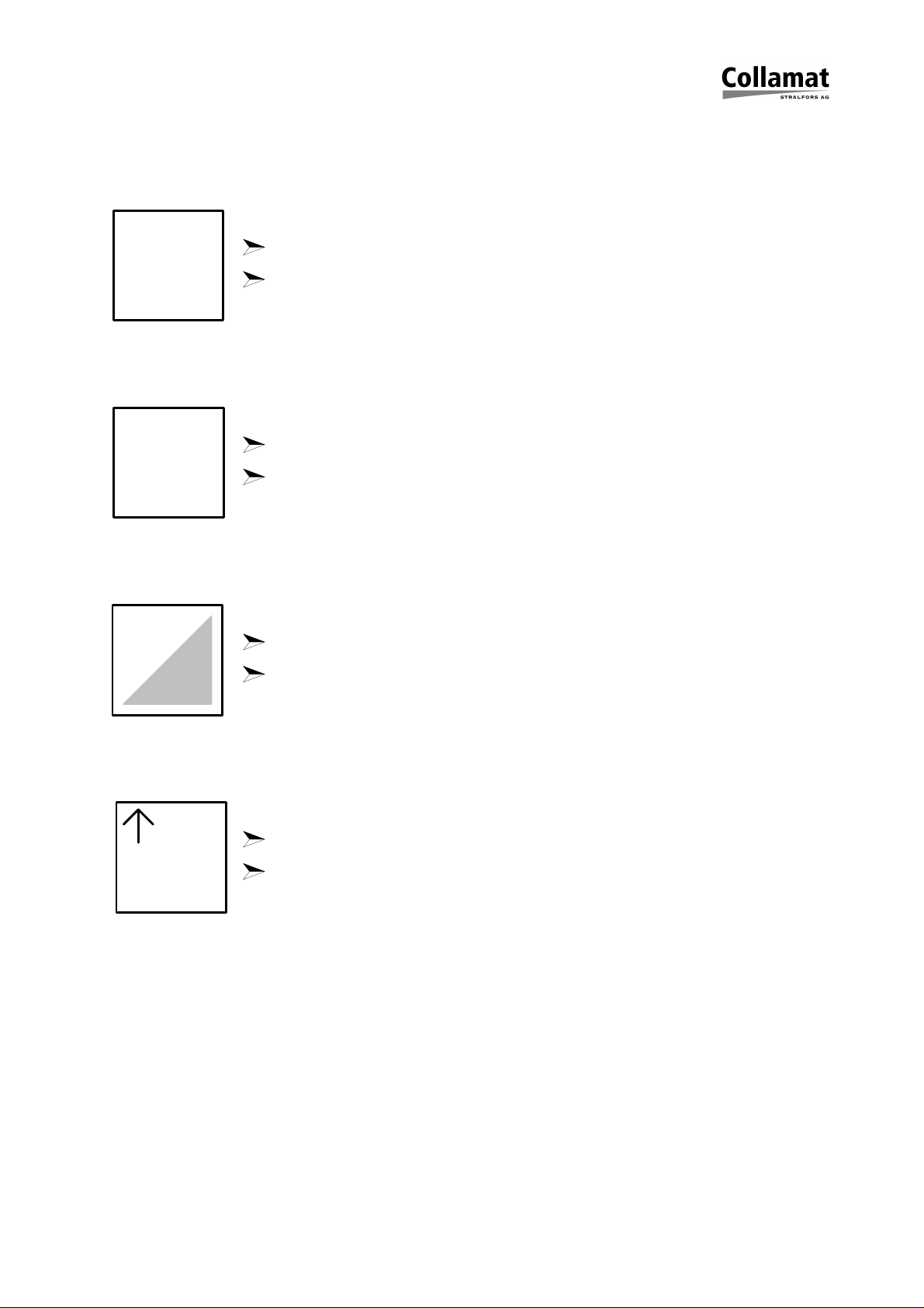
The keyboard of C8600 / C9100
Key ESC
ESC
Menu handling : One level higher
Number entry : Break of entry
Key ENTER
ENTER
Menu handling : One level lower
Number entry : Terminate entry
Number Keys and Period
0...9
Number entry
Special functions
Cursor Keys UP and DOWN
Selection of Menu Options
Selection of Functions
C91TR04E.SAM 10.09.98 WM Page 4 / 26
Page 5
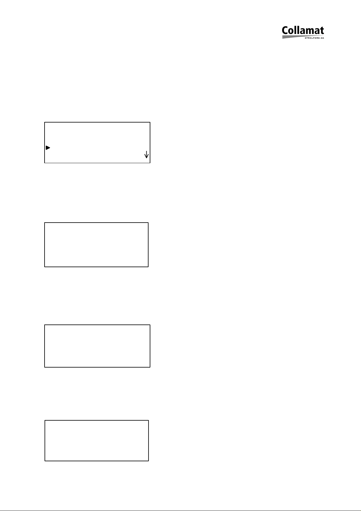
The menu types of C8600 / C9100
Four different types of menus are used:
1. Selection Menus
Selection of a menu option which is situated behind the activated line.
The arrow indicates more options available
LABELLING MODE
Label Jog
Select program
Information Displa
2. Function Menus
Selection of one function from several possible options.
Choice can be changed with the arrow keys.
SELECT COUNTER
Choice : Labels
3. Entry of Numbers
Numbers can be entered with the keys 0..9 and .
Change in steps of 1 are possible with the arrow keys.
PREDISPENSING
Value : 12.4 mm
4. Special functions
All menus with special functions show the handling on the LCD-display.
[UP/DOWN] Error-No.
[0/1] Continue/Stop
Continue at
Label Stock
C91TR04E.SAM 10.09.98 WM Page 5 / 26
Page 6
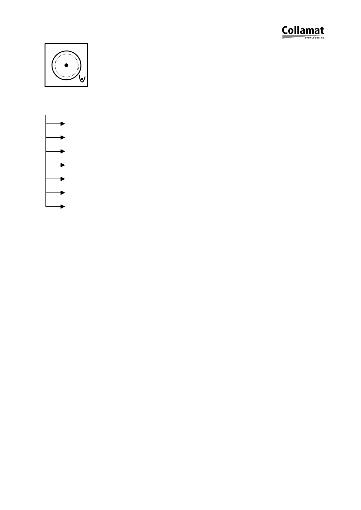
Menu tree Labelling
Labelling Mode
Label Jog
Select program
Information display
Reset Counter
Preset Counter
Select Counter (Labels / Goods / External)
Reset Nonstop
C91TR04E.SAM 10.09.98 WM Page 6 / 26
Page 7
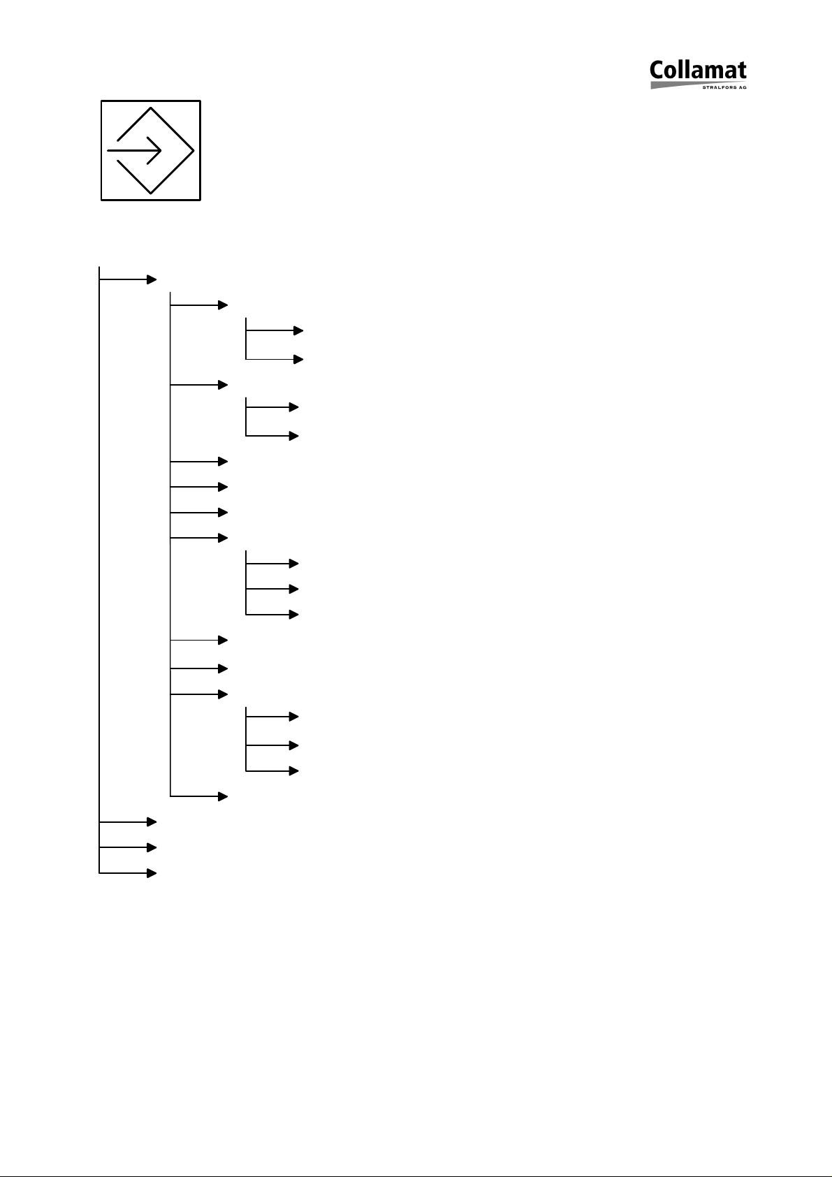
Programming
Change program
Menu tree Programming
Labelscanner Sensitivity
Auto adjust
Manual adjust
Label Length
Auto adjust
Manual adjust
Label Suppression
Predispensing
Position
Speed
Maximum Speed
Good Suppression
Labelling Mode
Profiling
Store Program
Program name
Program presets
Fixed Speed
Incremental Encoder
Measuring Scanner
Normal Labelling
Multiple Labelling
Delayed Predispensing
C91TR04E.SAM 10.09.98 WM Page 7 / 26
Page 8
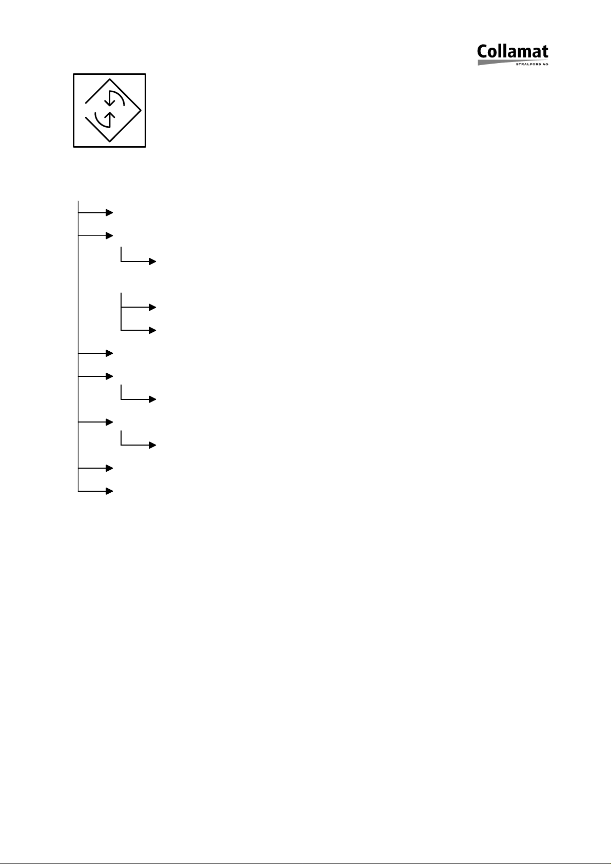
Menu tree Configuration
Configuration
User Menu
Language
Language (German / English / French / Italian)
User Level
Change Level
Enter Password
Error Handling
Nonstop-Labelling
Function (OFF / MASTER / SLAVE)
Adaptermagnet (OFF/ ON)
Adaptermagnet Release Delay
Motor direction (Right / Left)
Polarity IFEED (Normal / Inverse)
C91TR04E.SAM 10.09.98 WM Page 8 / 26
Page 9
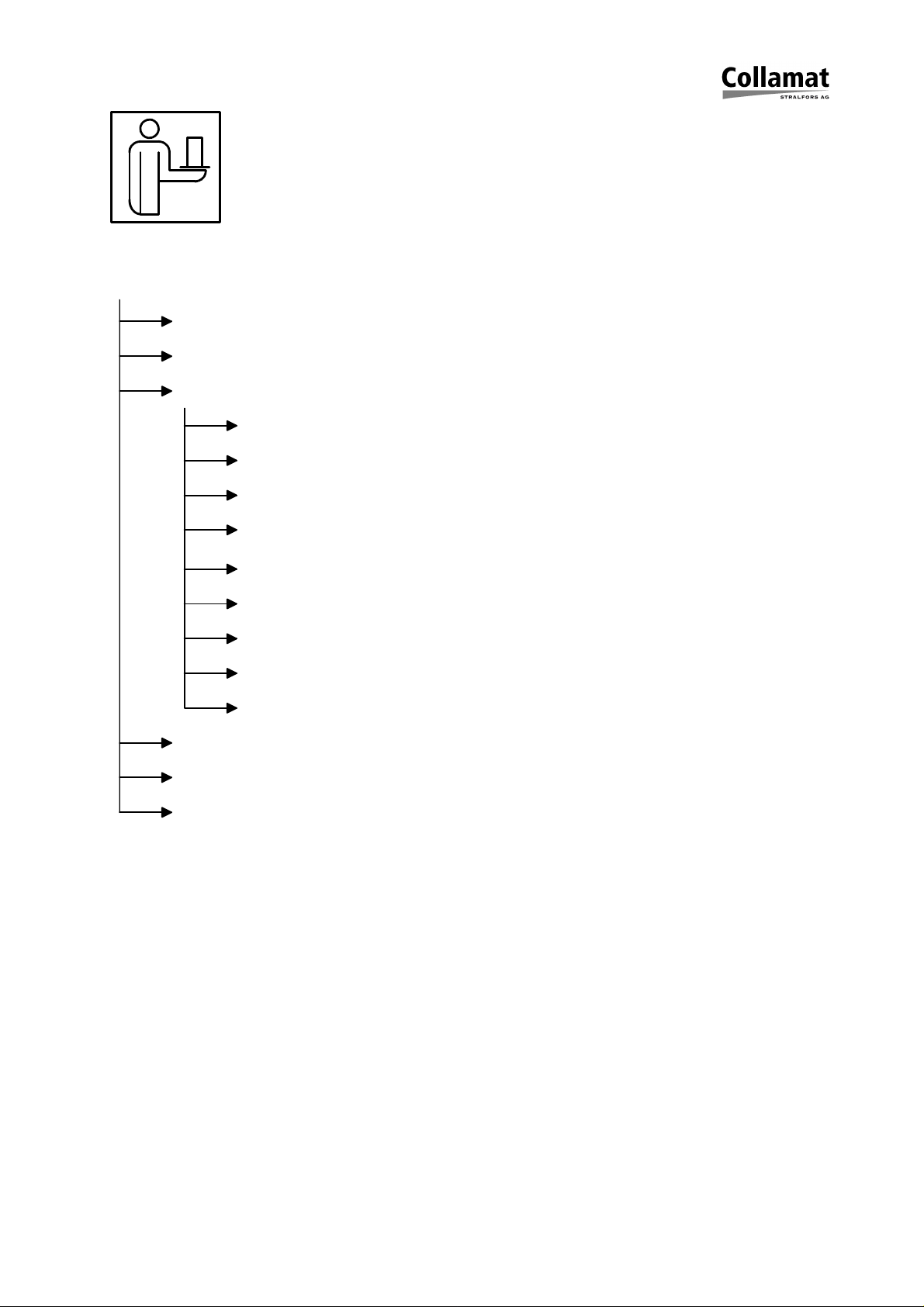
Menu tree Service Functions
Service functions
Software Version
Error Sequence
Selftest
RAM
EEPROM
Keys
LED
LCD
Backlight
IO Controller
IO Monitor
Drive
Working Time
Motor running
Remote Control
C91TR04E.SAM 10.09.98 WM Page 9 / 26
Page 10
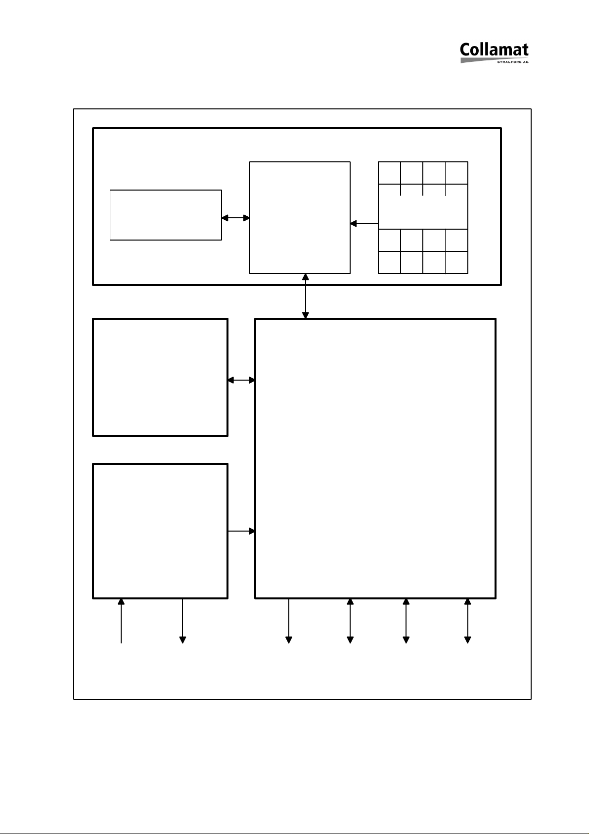
Block diagram of the monitor C9100
Controller Board
LCD-Display
4 Lines
20 Characters
Stepping Motor
Controller
3 Phases
Controller
Interface Board
- Power supply
- Signal conditioning
Keyboard
20 Keys
Supply Board
- Main switch
- Filter
- Voltage selector
- Transformer
Mains
Input
Mains
Output
switched
Stepper
Motor
- Connectors
Dispenser
GSC Control
(C9100)
Signals
C91TR04E.SAM 10.09.98 WM Page 10 / 26
Page 11
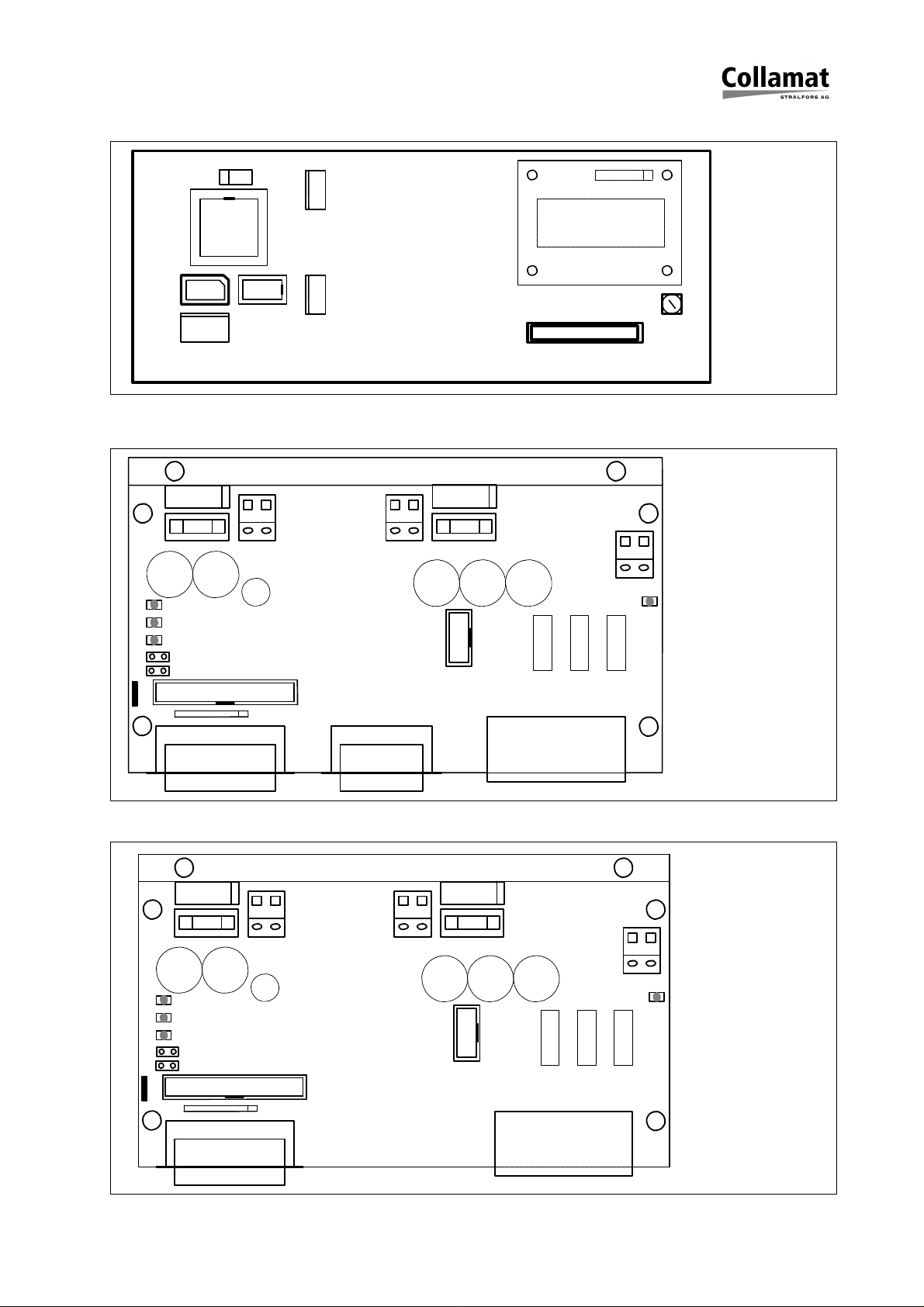
Controller board
IC3
IC9
IC6
IC5
Q1
IC1
IC7
Interface board C9100
F2
X14
+
LD2
LD3
LD4
GL2
X9
J1
~ ~
2 * violet 2 * orange
+
X1
X6
X11X12
X2
LCD DISPLAY
CONTRAST
RP1
X1
GL1
~
F1
~
+
X2
+
+
K1 K2 K3
X13
+
LD1
-
X3
Interface board C8600
GL2
F2
X14
+
LD2
LD3
LD4
X9
J1
~ ~
2 * violet 2 * orange
+
X1
X6
X3
X5
X7
X11X12
~
GL1
~
F1
+
X2
+
+
K1 K2 K3
X13
+
LD1
-
X7
C91TR04E.SAM 10.09.98 WM Page 11 / 26
Page 12
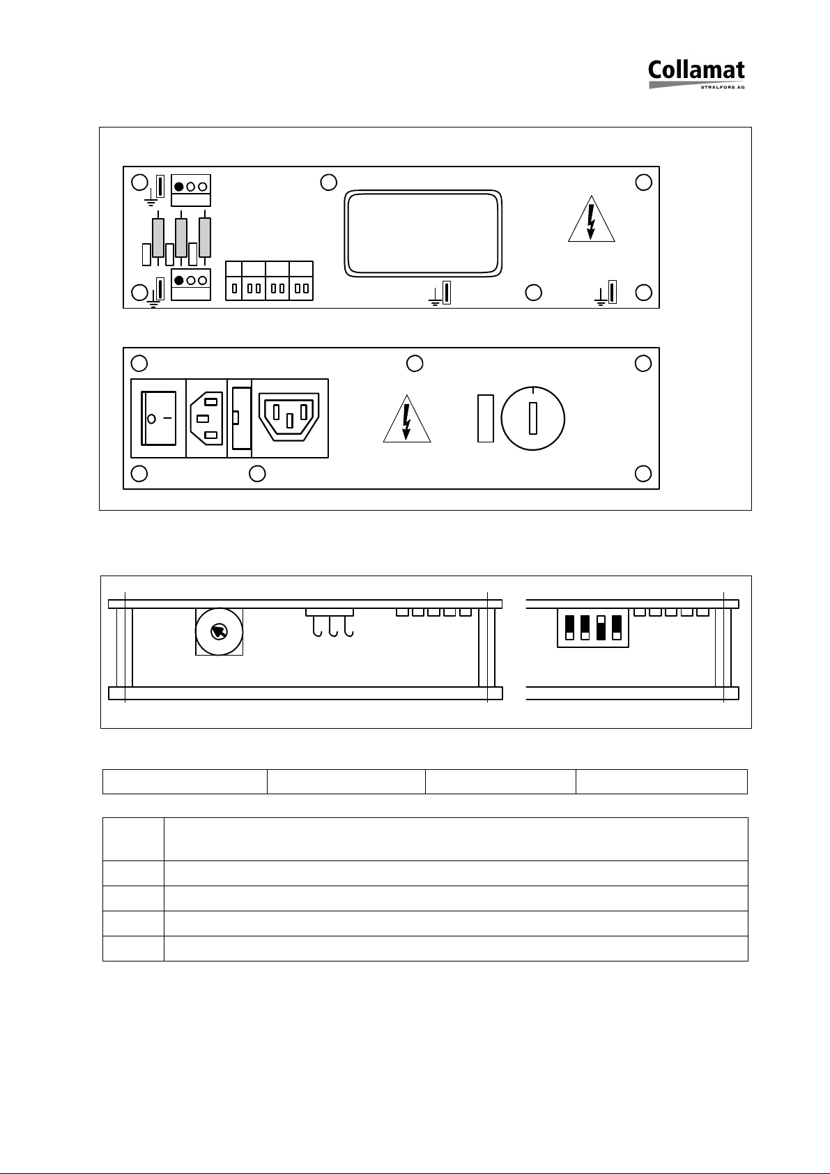
Mains filter board
DRIVER
4/5
4/5
520
526
MOTOR
Motordriver
X4
TRAFO
4219508
X5
4/5
4/5
1: brn/bn
2: red/rt
3: org/og
4: yel/gb
5: grn/gn
6: blu/bu
7: vio/vi
8: gry/gu
9: wht/ws
0: blk/sw
D
S2
S3
S1
LED 4
LED 5
LED 2
LED 3
LED 1
S3
S2
S1
LED 4
LED 5
LED 2
LED 3
LED 1
S1 : open S2 : closed S3 : open Selectorswitch : D
LED 1 lights up when the motordriver is operating properly. The supply voltage ex-
ceeds 80 VDC.
LED 2 lights up in case of a short-circuit between two motor phase leads.
LED 3 lights up in case of overtemperature (> 75°) at the heatsink.
LED 4 lights up in case of overvoltage (>140 V) during operation with brake.
LED 5 lights up in case of undervoltage (< 80 V).
C91TR04E.SAM 10.09.98 WM Page 12 / 26
Page 13
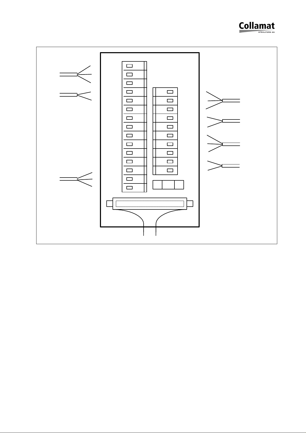
Connection box
Label Scanner
1
9
5
4
5
GND
LSC
+12V
TCY
+12V
GND
FLAP
GND
LLO
+12V
GND
1
Label Low Sensor
9
5
6
Unwinder
Traction Unit
1
9
5
+24V
GND
FEED
READY
+12V
GND
TUNIT
+12V
F1 5AT
+24V
GND
RWF
+12V
GND
+24V
1
1
Rewinder Full
9
5
6
Rewinder
1
1: brn/bn
2: red/rt
3: org/og
4: yel/gb
5: grn/gn
6: blu/bu
7: vio/vi
8: gry/gu
9: wht/ws
0: blk/sw
C91TR04E.SAM 10.09.98 WM Page 13 / 26
Page 14
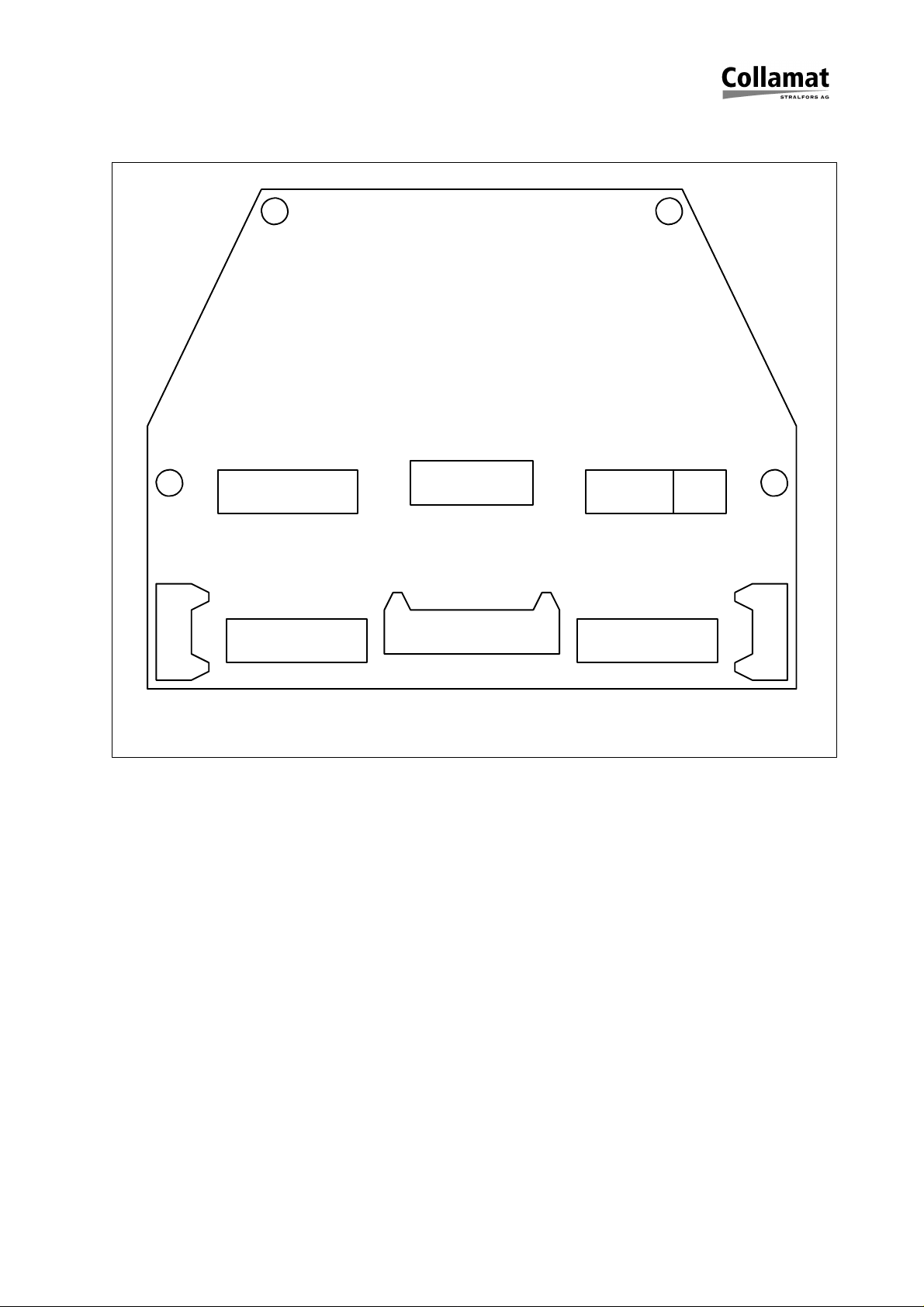
Traction unit C8600
GND
GSC3+
GSC3-
GND
NSTPI+
NSTPI-
GND
NSTPO
MOTOR
SCREENU1U2
V1
V2
W1
W2
SCREEN
U
SCREEN
PROTECTION
GROUND
W
V
E
E
E
X101
GND
brn
GSC1
yel
wht
GSC2
+12V
grn
GND
brn
LSC
wht
TCY
+12V
grn
brn
MONITOR-CABLE
+12V
grn
grn
yel
wht
X103
blu
org
red
MOTOR-CABLE
READY
+12V
GND
FEED
GND
brn
GND
TUNIT
gry
brn
yel/grn
yel/grn
LLO
wht
yel/grn
X102
+12V
C91TR04E.SAM 10.09.98 WM Page 14 / 26
Page 15
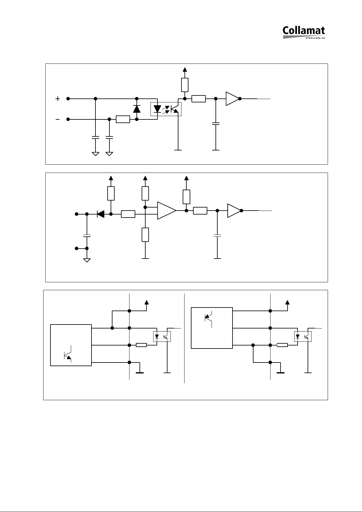
Inputs
+5V
Anode
Cathode
IN
GND
1n
1n
1N4148
1n
1N4148
2k2
2k2
100k
SFH6156-3
+12V+12V
6k8
+
LM339
3k3
1k8
10k
+5V
1k8
100k
(LSC:10k)
74AC14
10nF
74AC14
10nF
NPN-Sensor
OUT
GND
+12V
+12V
Anode
+
+
Cathode
-
GND
PNP-Sensor
+
OUT
GND
SensorSensor
+12V
Anode
+
Cathode
-
GND
+12V
MonitorMonitor
C91TR04E.SAM 10.09.98 WM Page 15 / 26
Page 16
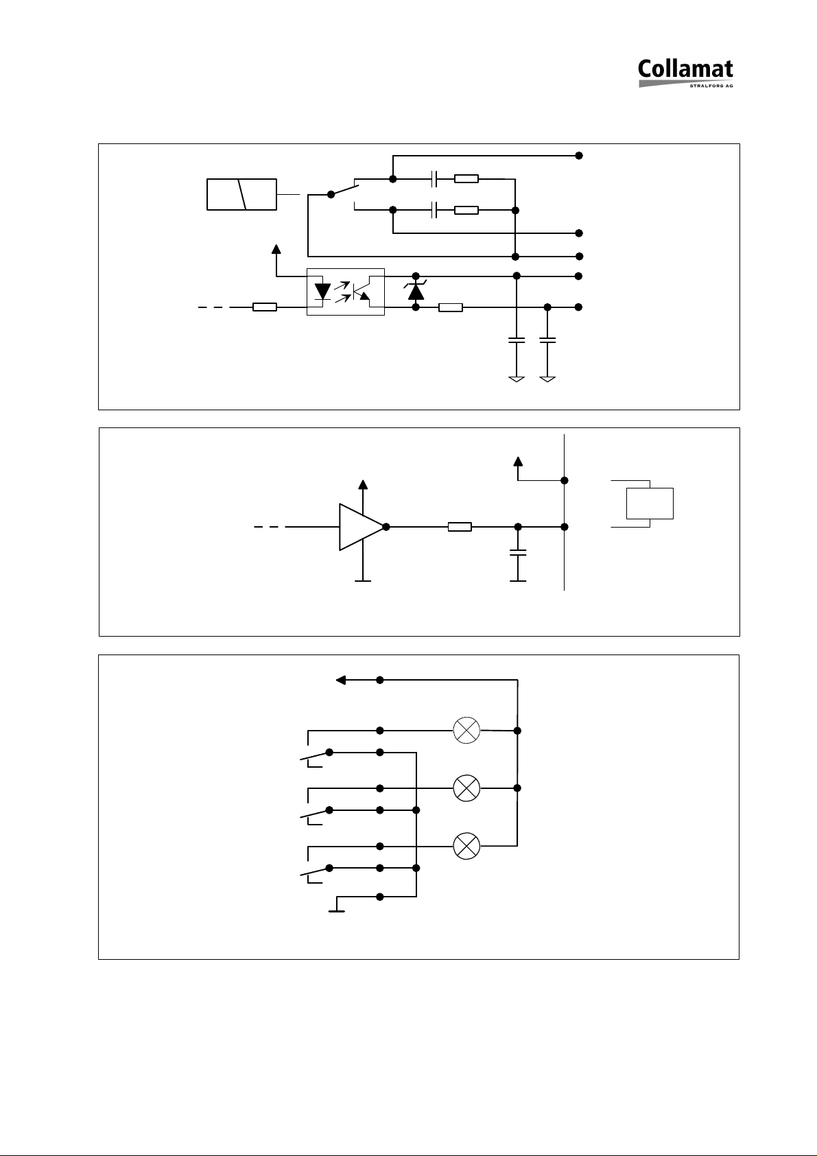
Outputs
Relais
IN
SFH6156-3
+24V
Z39V
ULN2003
Monitor
47n
100E
47n 100E
10E
10E
1n
+24V
1n
1n
R
Umax: 250VAC
Imax: 1A
A
C
+
Umax.: 24VDC
Imax: 25 mA
-
+24V
OUT
Umax: 24VDC
Imax: 100mA
R
L
+24V
RUN-A
RUN-C
NOK-A
NOK-C
ERROR-A
ERROR-C
GND
A5
GRÜN
B1
B2
ORANGE
B7
B8
ROT
B4
B5
A6
X7
C91TR04E.SAM 10.09.98 WM Page 16 / 26
Page 17
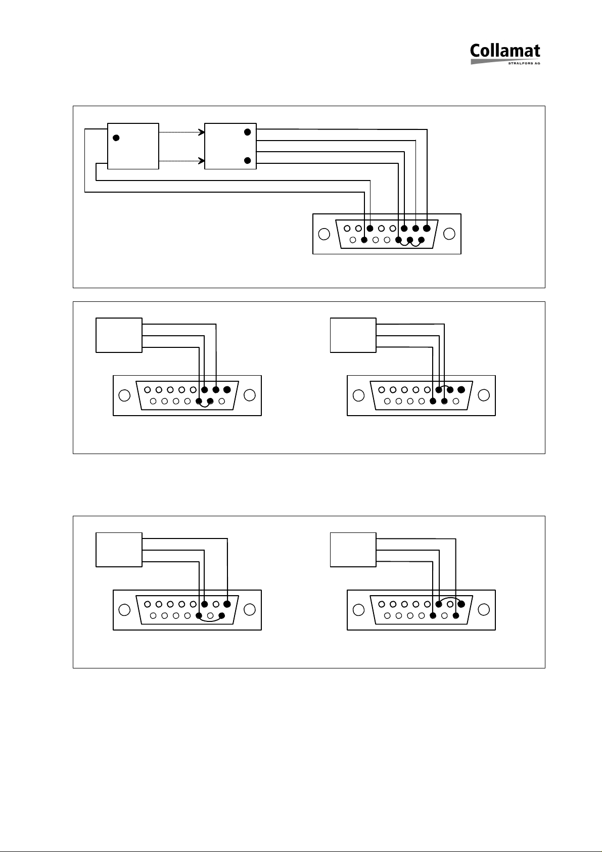
Connection of the goods scanners to the C9100
NPN
15
wht/ws
yel/gb
IR
GSC2GND
+12V
8
1
ben/bn
grn/gn
brn/bn GND
grn/gn +12V
9
GSC1GSC2GND
+12V
8
15
PNP
15
1
9
GSC2+
GND
+12V
8
1
9
Incremental encoder
GSC1-
NPN
8
15
GND
+12V
GSC1+
PNP
1
9
8
15
GND
+12V
1
9
C91TR04E.SAM 10.09.98 WM Page 17 / 26
Page 18
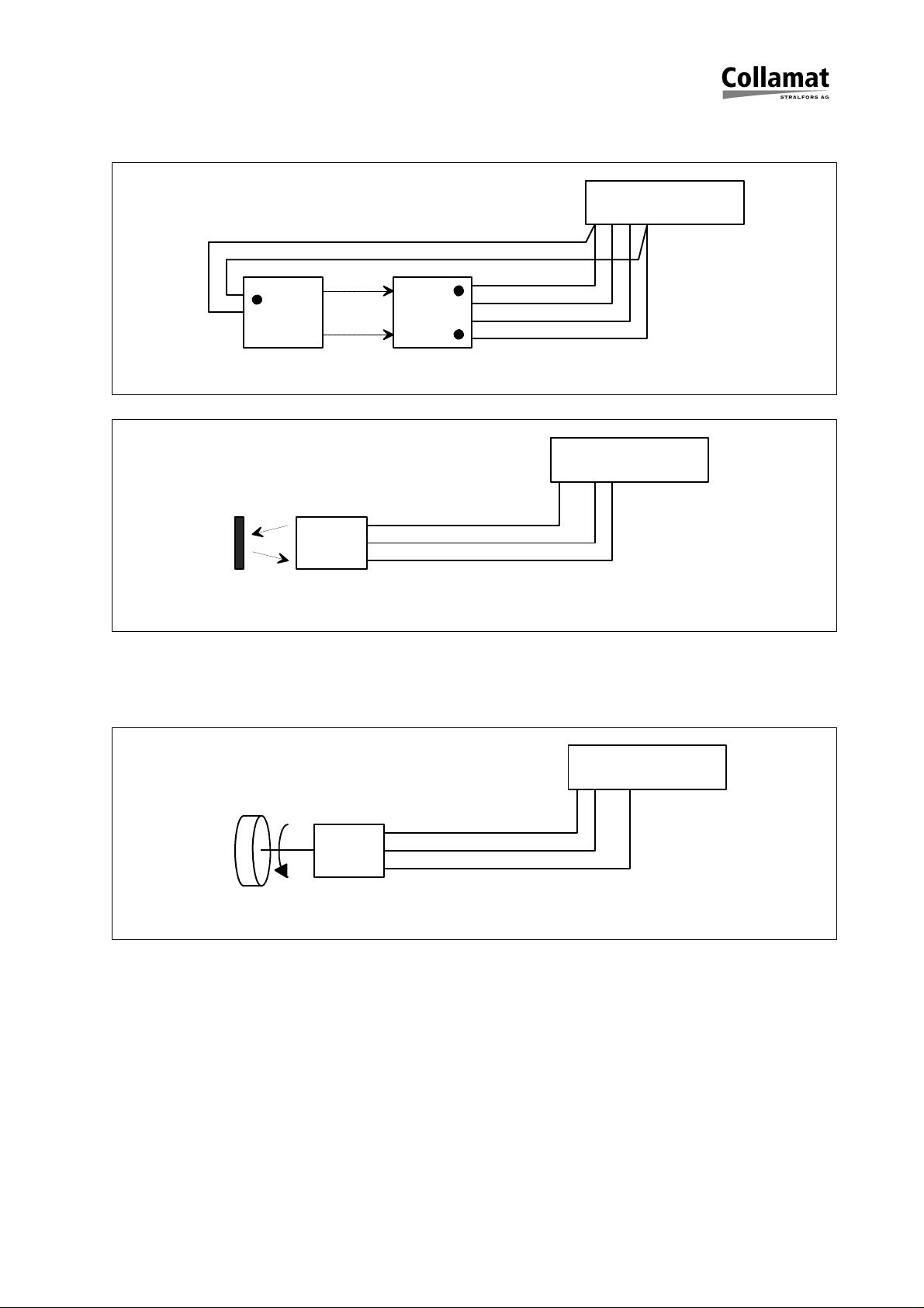
Connection of the goods scanners to the C8600
IR
NPN
GND
GSC2
+12V
brn/bn GND
grn/gn +12V
ben/bn GND
wht/ws GSC1
yel/gb GSC2
grn/gn +12V
GND
GND
GSC1
GSC2
GSC1
GSC2
+12V
GND
+12V
GND
LSC
+12V
LSC
TCY
+12V
GND
TCY
GND
Incremental encoder
NPN
GND
GSC1
+12V
GND
GSC1
+12V
GSC2
GND
LSC
TCY
+12V
GND
C91TR04E.SAM 10.09.98 WM Page 18 / 26
Page 19
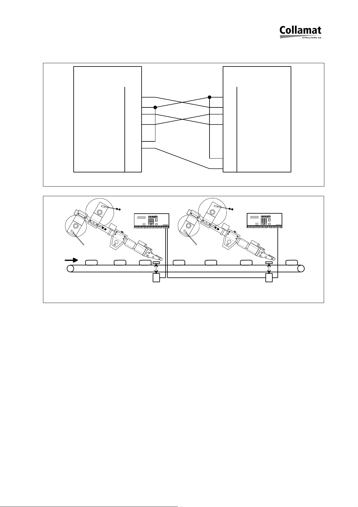
Nonstop with C9100
Master
GSC
+12V
NSTPI+
NSTPINSTP0
GND
GSC3+
GSC3GSC2+
GSC2-
Pin
11
13
5
7
6
12
4
10
1
COLLAMAT
1 2 3
4
7 8 9
5 6
0ESC ENTER
Slave
GSCPin
12V
11
NSTPI+
13
NSTPI-
5
NSTP0
7
GND
6
GSC3+
12
GSC3-
4
GSC2+
10
GSC2-
1
1 2 3
5 6
4
7 8 9
0ESC ENTER
&&
GUHL SCHEIBLERGUHL SCHEIBLER
TICKETS UND ETIKETTIER-SYSTEME
COLLAMAT
GUHL SCHEIBLERGUHL SCHEIBLER&&
TICKETS UND ETIKETTIER-SYSTEME
MASTER SLAVE
GSC2GSC2
C91TR04E.SAM 10.09.98 WM Page 19 / 26
Page 20
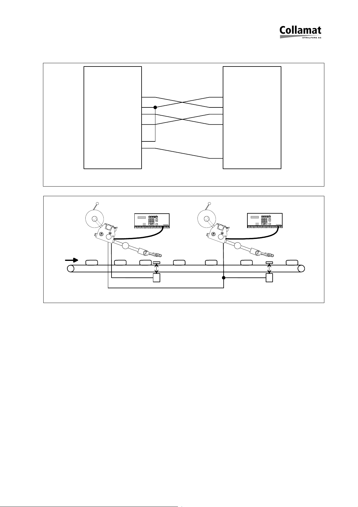
Nonstop with C8600
Master
+12V
NSTPI+
NSTPINSTP0
GND
GSC3+
GSC3-
GSC2-
Slave
12V
NSTPI+
NSTPINSTP0
GND
GSC3+
GSC3-
GSC2-
MASTER SLAVE
1 2 3
5 6
4
7 8 9
0ESC ENTER
COLLAMAT
&&
GUHL SCHEIBLERGUHL SCHEIBLER
TICKETS UND ETIKETTIER-SYSTEME
COLLAMAT
1 2 3
4
7 8 9
5 6
0ESC ENTER
GUHL SCHEIBLERGUHL SCHEIBLER&&
TICKETS UND ETIKETTIER-SYSTEME
GSC2
GSC2
C91TR04E.SAM 10.09.98 WM Page 20 / 26
Page 21
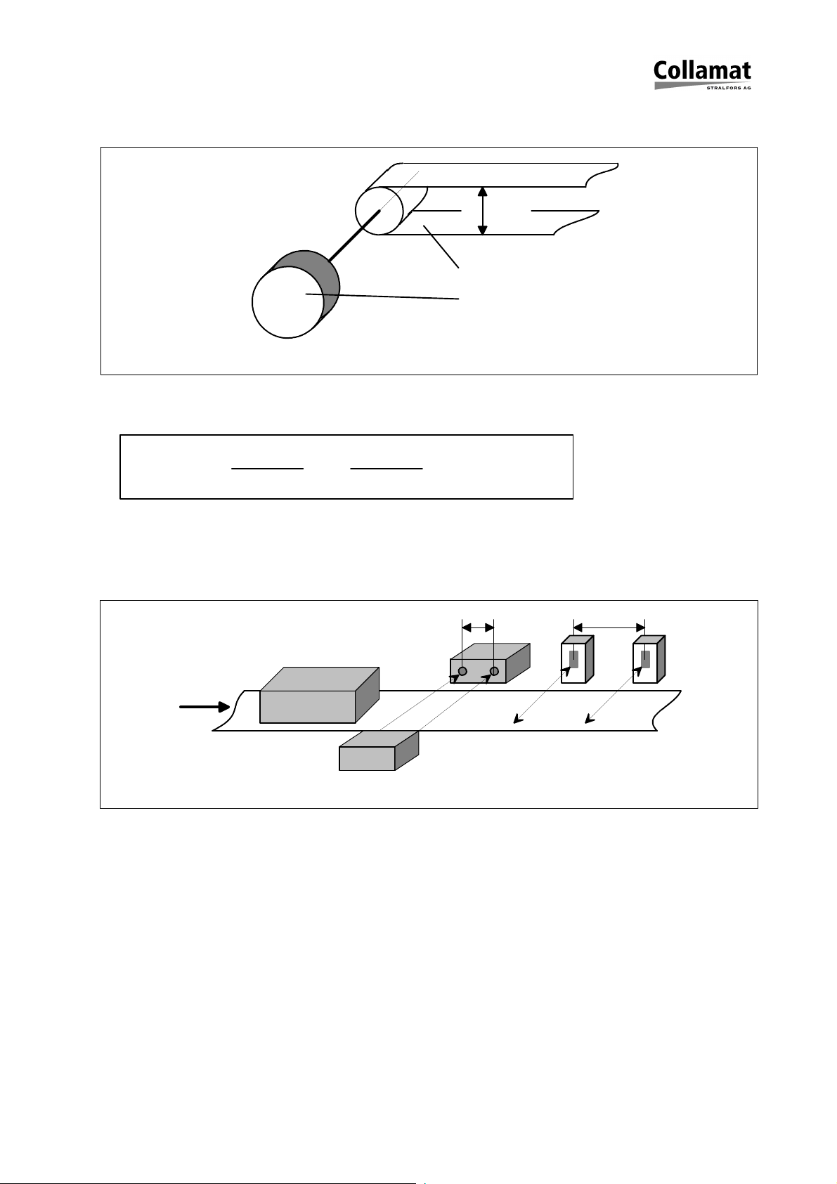
Incremental encoder
d
2
1
Example: Encoder gives 200 pulses per revolution. The distance d is 100 mm
Step =
d * Pi
=
314mm
Pulse
Measuring goods scanner
Product
200
GSC1
=
1.57mm
G&S: L = 14mm L
GSC2
GSC1
GSC2
C91TR04E.SAM 10.09.98 WM Page 21 / 26
Page 22
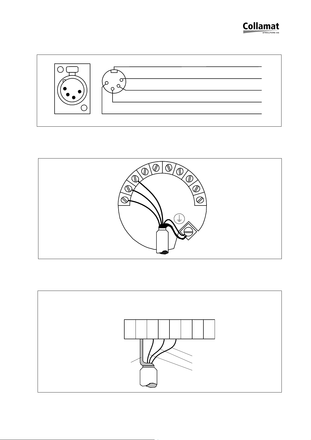
Motor and Motorcable
MOTOR
PUSH
4
1
4
1
3
2
3
2
Connection to the C9100 motor
3
2
1
Schirm/screen
gelb-grün/yellow-green
3
2
1
Connection to the C8600 traction unit
E
V
U
SCREEN
SCREEN
MOTOR-CABLE
SCREEN
C91TR04E.SAM 10.09.98 WM Page 22 / 26
W
E
1
2
3
E
Page 23
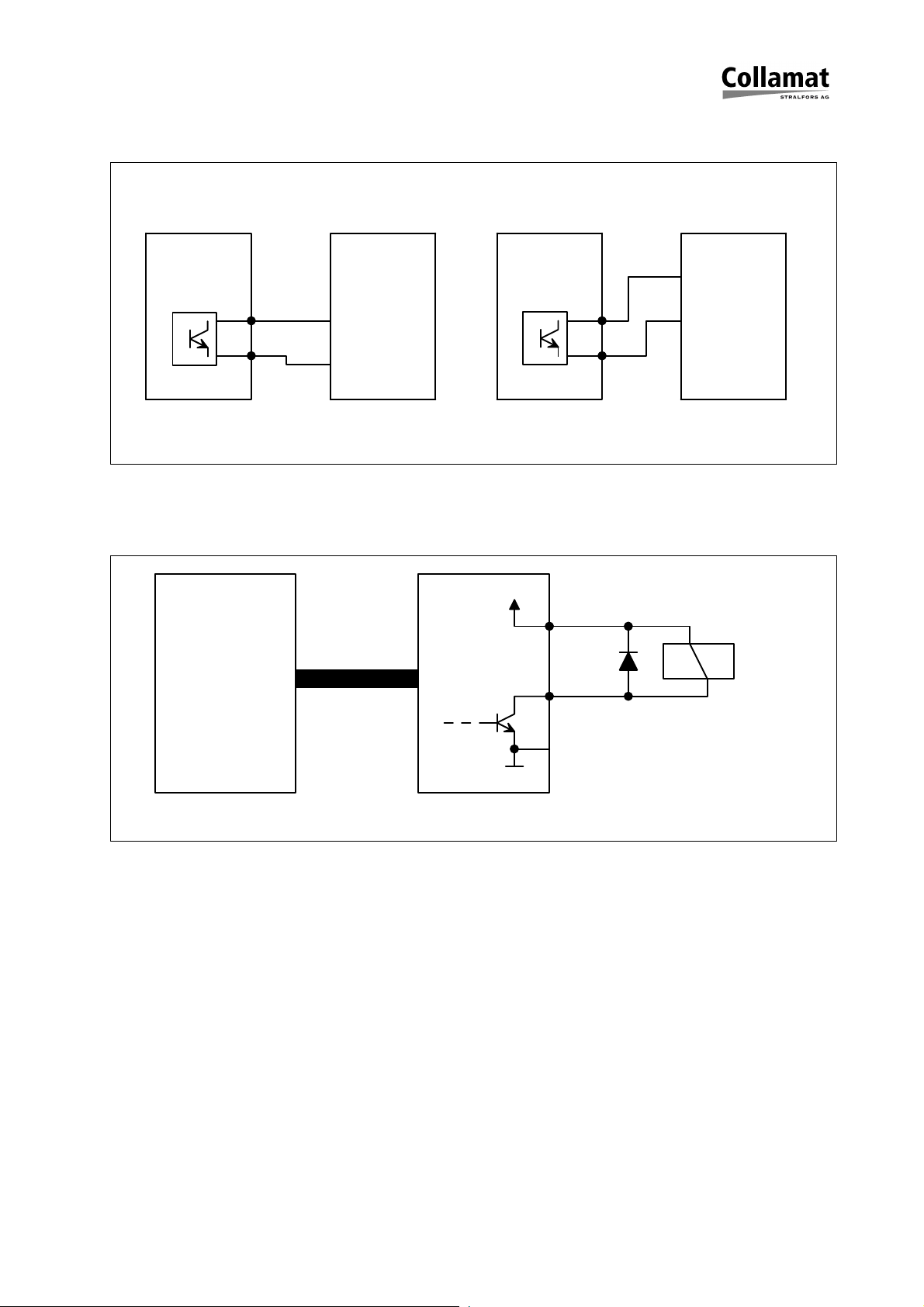
Connection of a Hotstamp
MONITOR
IFEED
+
-
X7A.3
X7A.4
NPN-Input PNP-Input
+12V / +24V
NPN
GND
MONITOR
CONTROL SIGNALSCONTROL SIGNALS
IFEED
X7A.3
+
X7A.4
-
Control of a magnet for the flapadapter on C9100
Monitor
+24V
+24V
FLAP
Pneumatic relais
1N
4007
HOT-STAMPHOT-STAMP
+12V / +24V
PNP
GND
Umax: 24VDC
Imax: 25 mA
DISPENSER
GND
Umax: 24V
Imax: 100mA
C91TR04E.SAM 10.09.98 WM Page 23 / 26
Page 24
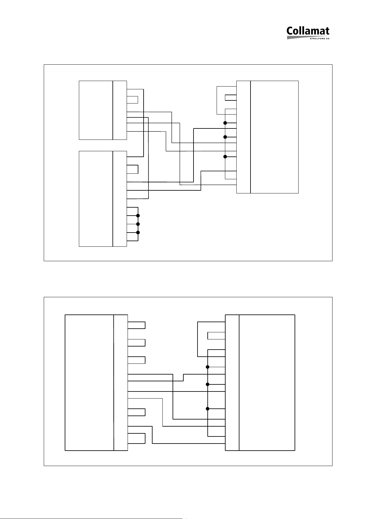
Diagnostic connector for C9100
DISPENSER CONTROL SIGNALS
FEED
FLAP
RWF
READY
LSC
LLC
TUNIT
GSC
GSC 1 NSTPI NSTPO
GSC 2 GSC 3 CLOCK
GSC 1+
GSC 2+
GSC 3+
+12V
NSTPI+
19
18
9
6
2
4
1
5
7
2
4
15
9
10
12
11
13
A1
A2
A3
A4
A5
8
A6
B1
B2
B3
B4
B5
B6
B7
B8
B9
STOP+
STOP IFEED+
IFEED +24V
GND
RUN.A
RUN C
RUN.R
ERROR.A
ERROR C
ERROR.R
NOK.A
NOK C
NOK.R
Diagnostic connector for C8600
DISPENSER CONTROL SIGNALS
FEED
GSC 1
NSTP0
NSTPI NSTPI+
+12V
LSC
GSC 2
READY
GSC 3 -
GSC 3+
+12V
LLO
TUNIT
CLOCK
17
10
20
25
24
23
4
3
6
21
22
14
9
5
16
A1
A2
A3
A4
A5
A6
B1
B2
B3
B4
B5
B6
B7
B8
B9
STOP+
STOP IFEED+
IFEED +24V
GND
RUN.NO
RUN.
RUN.NC
ERROR
ERROR.NC
NOK.NO
NOK.
NOK.NC
C91TR04E.SAM 10.09.98 WM Page 24 / 26
Page 25
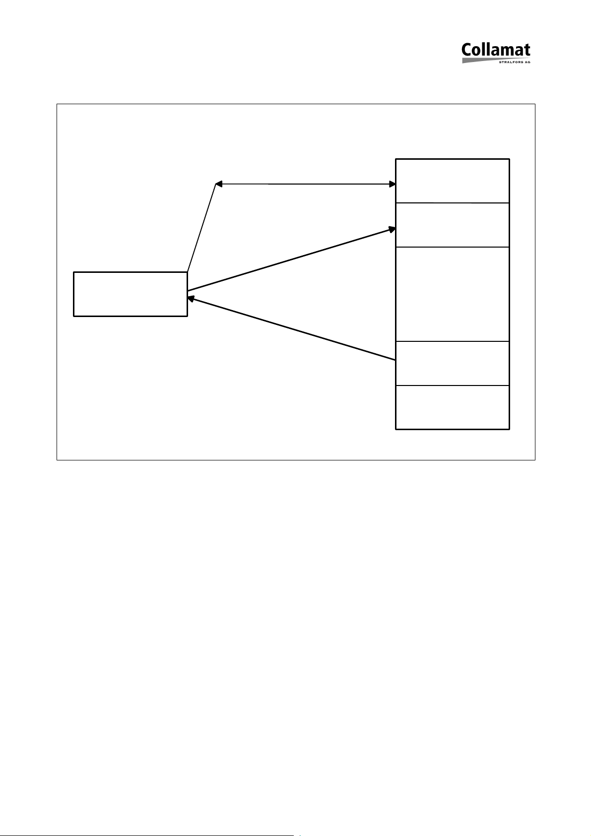
Program Memory
Working Memory
Program memory
Power up / down
Program #0
Program #1
store program
load program
Program #19
Program #20
C91TR04E.SAM 10.09.98 WM Page 25 / 26
Page 26
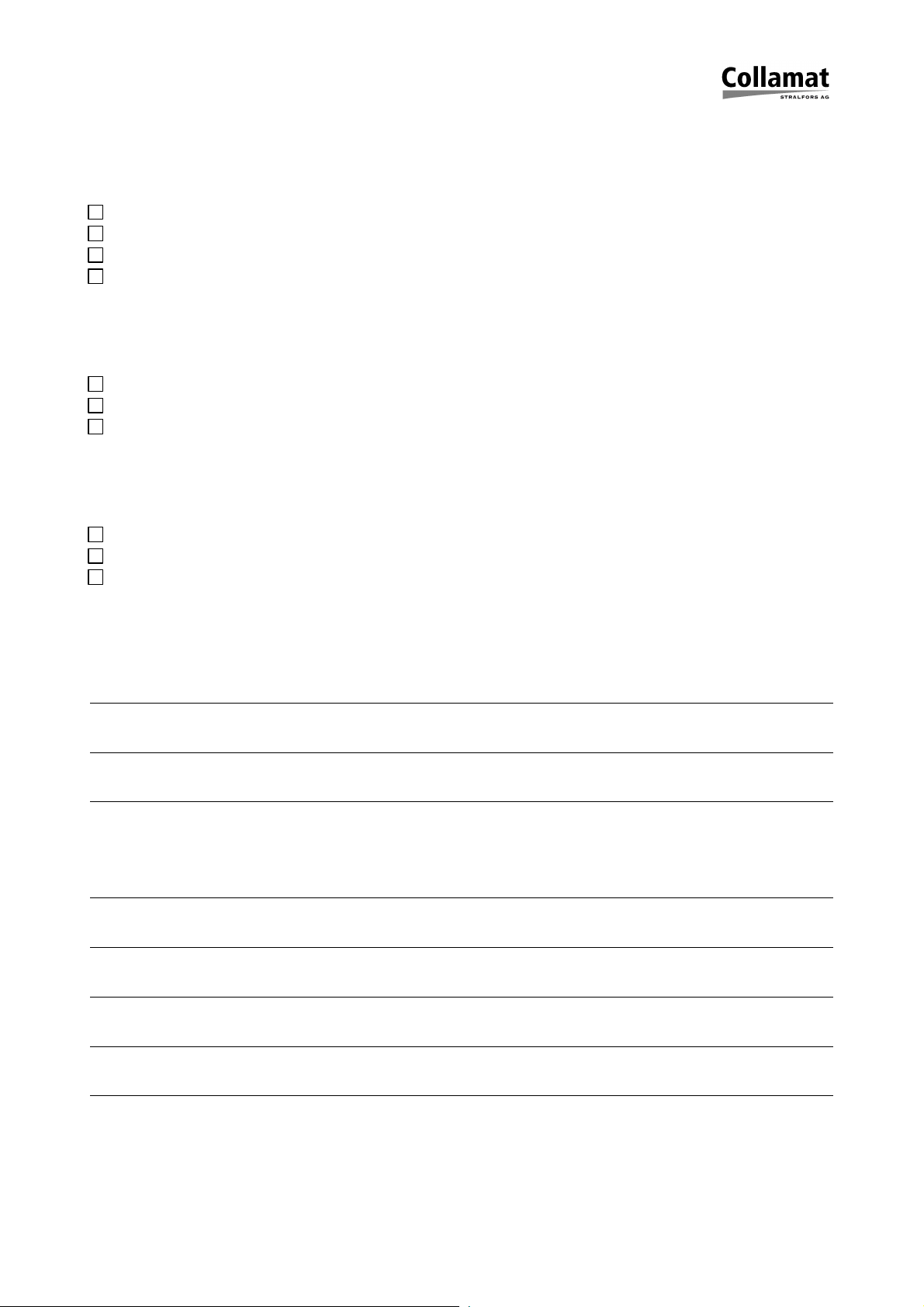
Your opinion about the training on Collamat C8600 and C9100
1. Presentation
Excellent
Good
OK
Not good
2. Contents
Correct
Too much
Too few
3. Practical training
Too difficult
Just OK
Too simple
4. What should be added or released ?
5. What do you think about the new Collamat C8600 / C9100 ?
C91TR04E.SAM 10.09.98 WM Page 26 / 26
 Loading...