

Page 1

HM Collamat AG
Bodenmattstrasse 34
CH-4153 Reinach
Switzerland
Phone +41 61 756 28 28
Fax +41 61 756 29 29
[email protected]
www.collamat.ch
5999.515-01E
Collamat 3600
Technical handbook
Page 2

Index
1 Safety advices ..................................................................... 4.......
1.1 Important Warnings .............................................................. 4.......
Page
1.2 Danger Indications
1.3 Symbol descriptions .............................................................. 5.......
2 Introduction ........................................................................ 6.......
2.1 General informations
2.2 The labeler C3600 ............................................................... 6.......
2.2.1 Prevention of accidents ......................................................... 7.......
2.2.2 Noise suppression .............................................................. 7.......
2.2.3 Mechanical stability ............................................................. 7.......
2.3 Assembly parts
3 Mechanical adjustments ............................................................ 9.......
3.1 Traction unit ...................................................................... 9.......
3.1.1 Threading the labelweb ......................................................... 9.......
3.1.2 Adjustment of rewinder coupling force .......................................... 9.......
3.1.3 Readjustment of paper brake ................................................... 10.....
3.1.4 Longitudinal adjustment on the module rail ..................................... 10.....
3.2 Flap adapter ..................................................................... 11.....
3.2.1 Inclination adjustment of flap adapter
...............................................................4.......
.............................................................6.......
...................................................................8.......
...........................................11.....
3.2.2 Adjustment of the pressure roller of the flap adapter ............................ 11.....
3.3 Adjustment of the optical label scanner ........................................... 12.....
3.4 Adjustment of the mechanical label scanner ...................................... 13.....
4 Technical description ............................................................... 14.....
4.1 Dispenser board .................................................................. 14.....
4.1.1 Power supply ................................................................... 14.....
4.1.2 Motordriver ..................................................................... 14.....
4.1.3 Controller
4.2 Signals and connection diagrams ................................................. 15.....
4.2.1 Inputs .......................................................................... 16.....
4.2.2 Outputs ........................................................................ 16.....
4.2.3 Isolated output IFEED .......................................................... 17.....
4.2.4 Open-Collector-output IFEED ................................................... 17.....
4.2.5 Currentsource-output ........................................................... 17.....
4.3 Connection diagrams BUS X101, X102 ........................................... 18.....
4.4 Transformer wiring
4.5 Connection of the mains input .................................................... 19.....
.......................................................................14.....
...............................................................18.....
4.6 Grounding of the labeler .......................................................... 19.....
4.7 Connection of the mains output ................................................... 20.....
5999.515-01E 12.06.2007 WM Page 1 / 47
Page 3

Index
4.8 Connection of the frontpanel ..................................................... 20.....
4.9 Motor and motorcable ............................................................ 21.....
Page
5 Firmware
5.1 Normalmode ..................................................................... 22.....
5.2 DIL-switches ..................................................................... 23.....
5.2.1 DIL-switch TEST
5.2.2 DIL-switch DIR ................................................................. 23.....
6 Trouble shooting ................................................................... 24.....
6.1 Fuses ............................................................................ 24.....
6.2 Status LEDs ...................................................................... 24.....
7 Peripheral units and sensors
7.1 Optical label scanner ............................................................. 25.....
7.2 Goods scanners .................................................................. 25.....
7.2.1 G&S measuring IR-scanner ..................................................... 25.....
7.2.2 NPN-Reflective scanner ........................................................ 25.....
7.3 Magnet adapter .................................................................. 26.....
7.4 Flatprinting unit ................................................................... 27.....
7.4.1 Flatprinter board ................................................................ 27.....
8 Control signals for external units
...........................................................................22.....
...............................................................23.....
.......................................................25.....
....................................................28.....
8.1 How to connect a goods scanner ................................................. 28.....
9 Electrical installation ................................................................ 29.....
9.1 Introduction ...................................................................... 29.....
10 Testmode .........................................................................
10.1 Test software ...................................................................
10.1.1 Motortest ......................................................................
10.1.2 Motor intervall test .............................................................
10.1.3 BUS-signal selftest ............................................................
10.1.4 Signal display .................................................................
10.1.5 DIL-switch settings ............................................................
10.1.6 Potentiometer settings ........................................................
10.1.7 Firmware Version .............................................................
11 Control of a hotstamp with the IFEED signal .......................................
12 Cabling and setting up
12.1 Cabling
12.2 Setting up .......................................................................
.........................................................................
.............................................................
.....
.....
.....
.....
.....
.....
.....
31.....
32
32
33.....
33
34.....
34.....
34.....
35
36
37
37
37.....
13 Version numbers ..................................................................
14 Glossary and terms ................................................................
5999.515-01E 12.06.2007 WM Page 2 / 47
38.....
38.....
Page 4

Index
Page
14.1 Short cuts .......................................................................
14.2 Signals ..........................................................................
14.3 Terms ...........................................................................
15 Technical data ....................................................................
15.1 Dimensions - Systemdesign ..................................................... 42.....
18 Trouble shooting ..................................................................
18.1 Trouble shooting Collamat 3600 .................................................
18.2 Trouble shooting checklist .......................................................
Appendix Spare parts Collamat 3600
.....
.....
38.....
38
39.....
40.....
43
43.....
48.....
5999.515-01E 12.06.2007 WM Page 3 / 47
Page 5
1 Safety advices
1.1
Important Warnings
Before installing and operating the Collamat 3600 read following safety
instructions:
The labeler C3600 is exclusively determinated for labelling goods.
The installation of a Collamat 3600 has to be done by a trained specialist.
For this you have to consider the national specific regulations of
prevention of accidents
mechanical stability
construction of electrical and mechanical systems
noise suppression
Take notice to the technical data of the Collamat 3600. Especially the environment conditions must be observed.
The operation of the Collamat 3600 must be done by trained personnel.
In case of non-authorized modification guarantee will fall.
Before connecting non-standard products ask your competent technical supporter.
1.2
Danger Indications
The safety symbols and danger advices on the Collamat 3600 and in this manual must
strictly be observed.
Before connecting or disconnecting the labeler to or from the main, it must be
switched off.
The labeler C3600 may only be opened by authorized personnel.
Before opening the labeler C3600, it must be separated from the main power.
It exists danger of pinching hairs, jewelry, ties, clothes etc. into the traction unit
It exists danger of injury by cutting fingers in the area of the paper web.
It exists danger of injury in the area of the dancer of the unwinder of the Collamat 3600.
It exists danger of injury in the area of the paper stockcontroller of the Collamat 3600.
For operation on the Collamat 3600 the operating personnel must keep to a safely
place to prevent injury from the products being labeled.
5999.515-01E 12.06.2007 WM Page 4 / 47
Page 6
1.3 Symbol descriptions
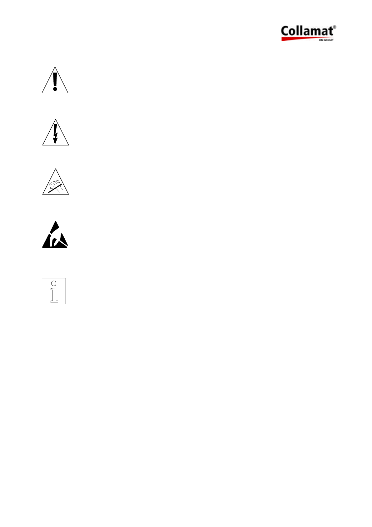
ATTENTION
Indicates danger of damaging the Collamat 3600 or other system components, with a potential consequential danger of injuries.
DANGER
Indicates an immediate hazard for persons.
DANGER
Shock hazard due to high voltage at component.
DANGER
Hazard due to high temperature component.
ATTENTION
ESD warning (Electro Static Discharge). The PC boards or component may
only be touched in an electrostatically protected environment.
NOTE
Important or additional information to Collamat 3600 or to the documentation.
5999.515-01E 12.06.2007 WM Page 5 / 47
Page 7
2 Introduction
2.1 General informations
This technical handbook describes the construction and the function of the Collamat 3600. In
addition to the operating instructions, it contains the necessary tips and adjustments to get optimum use of the Collamat 3600. The descriptions of each electrical or mechanical device also
helps for quick error analysis and error elimination.
We recommend you to replace the complete electronic boards. Return it to Collamat Stralfors
AG or to its representative for repair. You can then feel sure, that the high quality standard of
the Collamat 3600 can also be guaranteed after repair.
2.2 The labeler C3600
Special characteristics of the Collamat 3600:
resistant to wear, no clutch/brake-system
robust, stable
easy installation and operation due to the modular construction
quick change-over to other labelling tasks
high performance
high reliability
latest SMD-technology
high precision 2-phase steppermotor
The traction unit as well as the other peripheral assemblies are mounted on a modular rail. The
control electronics of the peripheral units are built in the units. The units are controlled and
driven by signals of the bussystem inside of the modular rail.
The operating elements for dispensing speed, predispensing, optical label scanner, as well as
the mains switch are placed right on the body of the traction unit itself. All parts are corrosionproof, the feedroller of the traction unit is provided with a special coating for permanent nonslip
torque transmission onto the paperweb. The rewinding force of the rewinder as well as the
braking power of the paper brake are adjustable at the traction unit from the outside.
The installation of the Collamat 3600 must be done by trained personnel. For this you have to
consider the national specific regulations of:
prevention of accidents
noise suppression
mechanical stability
construction of electrical and mechanical systems
5999.515-01E 12.06.2007 WM Page 6 / 47
Page 8
2.2.1 Prevention of accidents
While installing and connecting the Collamat 3600 take care that the signal cables and power
cables can't become obstacles. The cables must be placed and installed according to the national safety requirements. Take care that the signal cables are not placed beneath power
cables.
The power switch and the controll elements must easily be accessible.
2.2.2 Noise suppression
The dispenser C3600 is shielded according to the CE directives. Only cables which are certificated by Collamat Stralfors AG may be used for connecting the dispenser to the peripheral
units and the mains power. Additional peripheral units must be connected to the auxiliary
mains terminal of the dispenser. These assemblies must be certificated by Collamat Stralfors
AG.
2.2.3 Mechanical stability
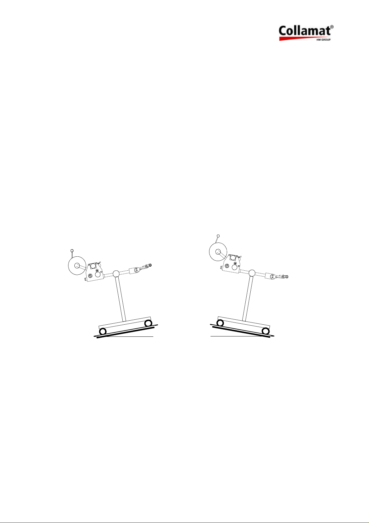
If the Collamat 3600 is used on a movable stand, this stand must be capable to be tilt 10° in
each direction. See also following figure 1:
10°
10°
Figure 1: Stability of the stand
5999.515-01E 12.06.2007 WM Page 7 / 47
Page 9
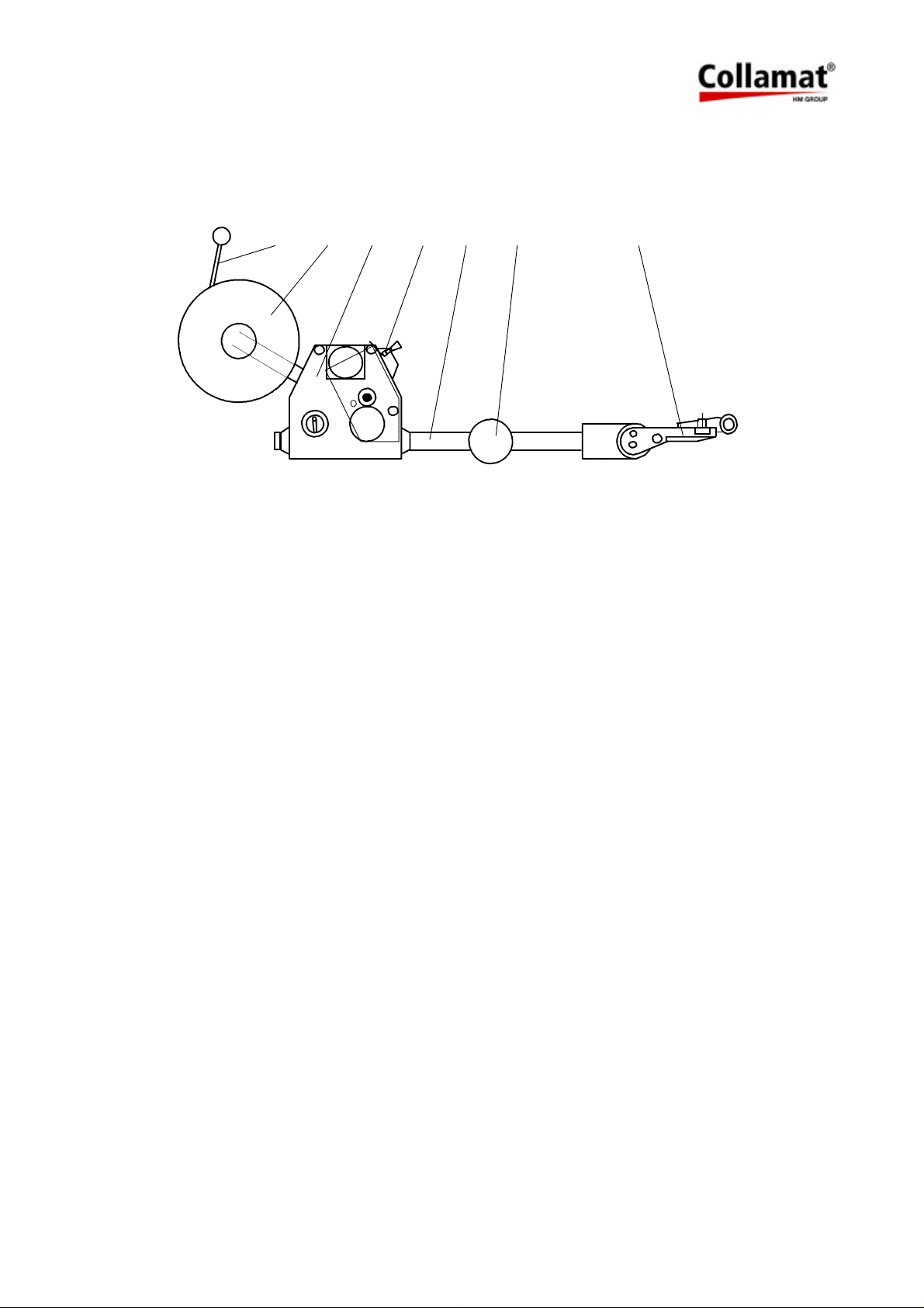
2.3 Assembly parts
The assembly parts are mounted and placed on a modular rail. Following figure 2 shows these
assembly parts with their names on the modular rail:
1 2
Figure 2: Assembly parts
Legend
Unwinder dancer
1.
Unwinder
2.
Traction unit
3.
Paper brake
4.
3
4 5
Modular rail
5.
Support
6.
Adapter (optional with magnet)
7.
6
7
5999.515-01E 12.06.2007 WM Page 8 / 47
Page 10
3 Mechanical adjustments
3.1 Traction unit
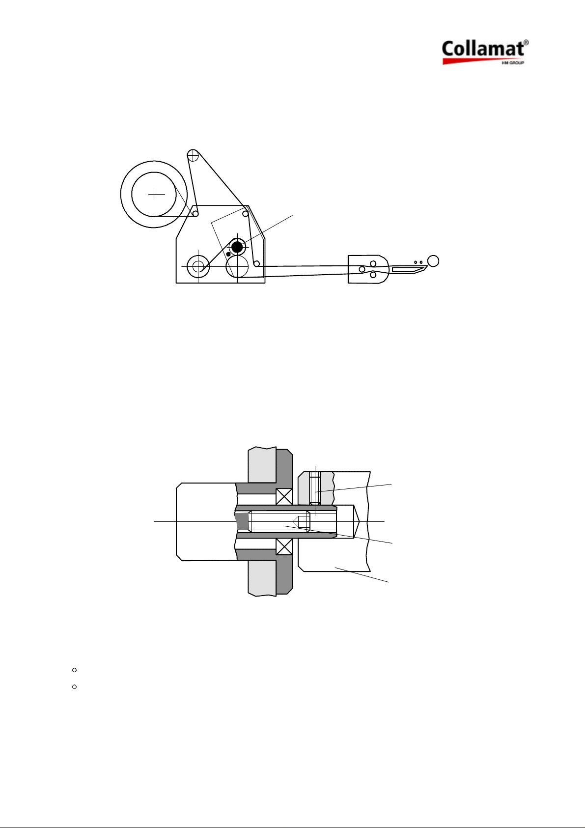
3.1.1 Threading the labelweb
1
Figure 3
Thread the labelweb as shown in figure 3 up to the dispensing edge and draw it out by approx.
1 m. Detach the labels from the paperweb at the drawn-out web. Then open the pinchroller by
turning the knob (1), place the paperweb over the dispensing edge and finish threading the paperweb as shown in figure 3. Close the pinchroller. Adjust the side guides of the paperweb
well, leaving 0.5 mm free space to the paperweb's edge.
3.1.2 Adjustment of rewinder coupling force
3
2
1
Figure 4
The coupling force of the rewinder is factory-set. Proceed as follows if out of adjustment:
Detach winding spindle (1) after unscrewing the M5-bolt (3). Screw M8-bolt (2) accordingly:
in= harder coupling
out= softer coupling
5999.515-01E 12.06.2007 WM Page 9 / 47
Page 11
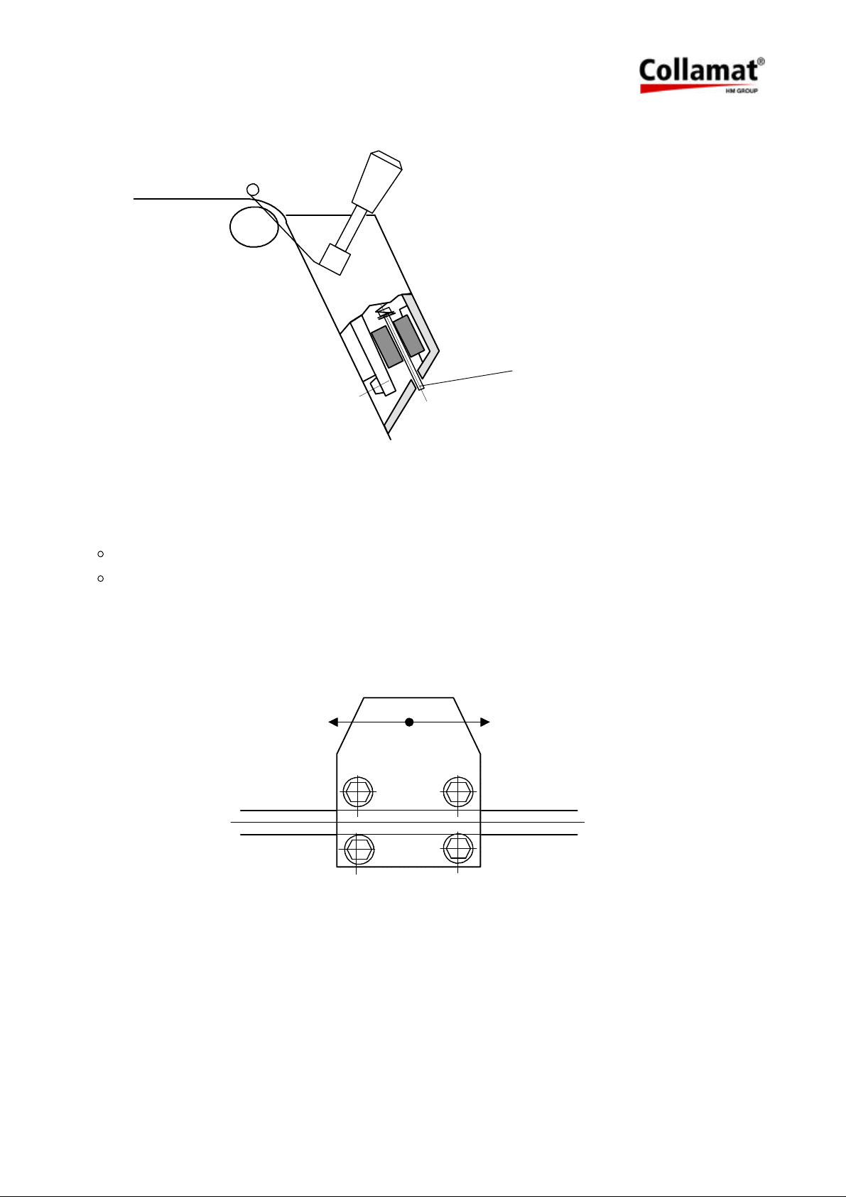
3.1.3 Readjustment of paper brake
2
Figure 5
The braking force is factory-set to an optimum value. Should it, however, be unadjusted, read-
just it with the M3-bolt (2) in the web-end controlbox of the traction unit, from the outside.
Screw in bolt= higher braking force
Unscrew bolt= lower braking force
3.1.4 Longitudinal adjustment on the module rail
Figure 6
Unscrew 4 bolts with special tool (wrench for socket head cap screws 5 mm) one half turn
(adapter only 2 bolts).
Move device, observing scale on module rail. Then tighten bolts equally.
5999.515-01E 12.06.2007 WM Page 10 / 47
Page 12
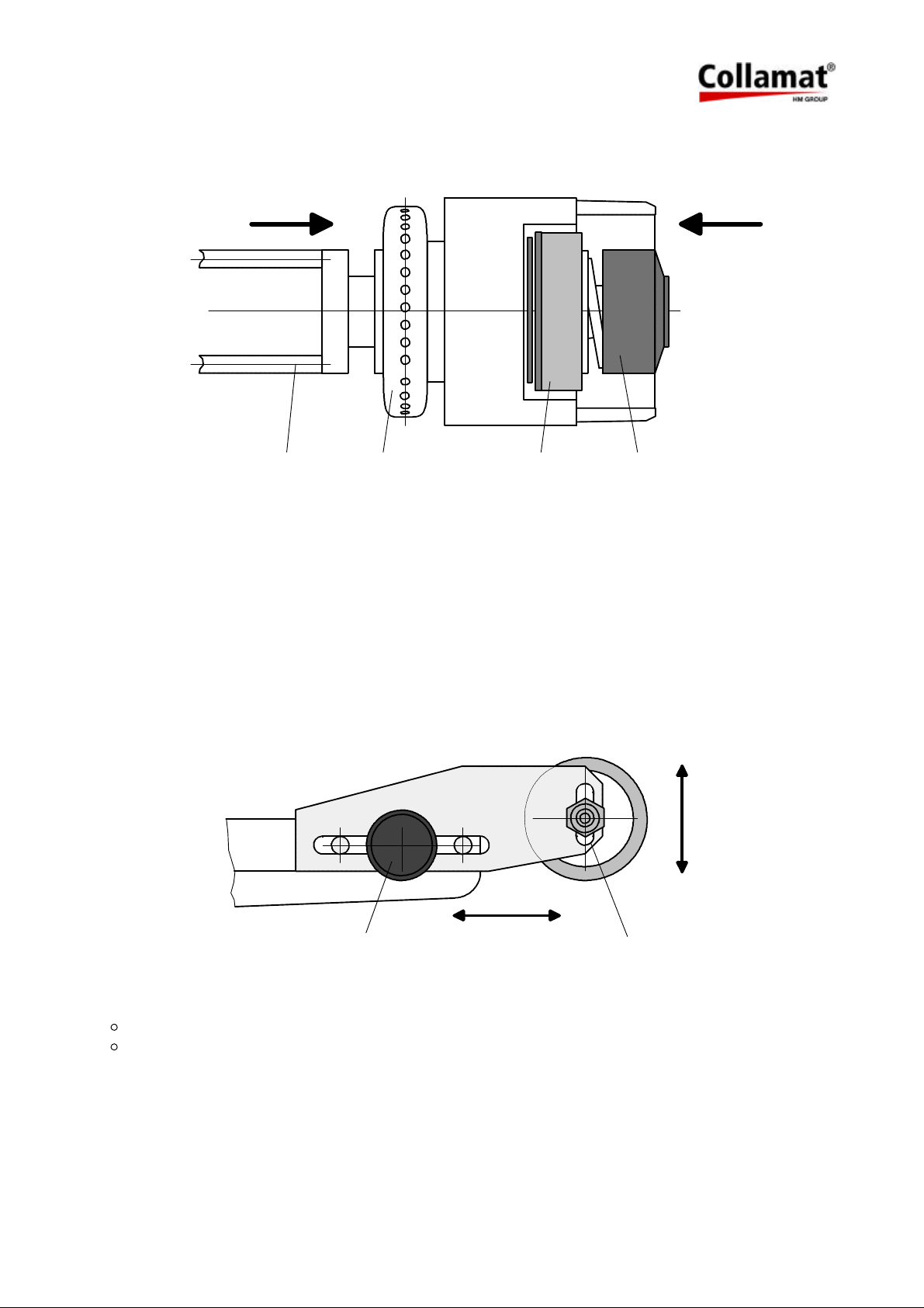
3.2 Flap adapter
3.2.1 Inclination adjustment of flap adapter
12 3 4
Figure 7
The inclination of the flap adapter can be changed against the module rail: unscrew nut (1) with
two turns (refer to figure 7), with special hexagonal spanner (included as accessory). Push
adapter in the direction indicated by the arrow (2), turn to desired setting at ring (3). Retighten
nut (1).
The pressure force of the flap adapter without magnet or of the magnetic flap adapter is variable: push in button (4) in the direction indicated by the arrow, twist for appropriate spring tension and adjust until it meets the next stop.
3.2.2 Adjustment of the pressure roller of the flap adapter
5 6
Figure 8
The pressure roller of the adapter can be adjusted depending on the labels and goods:
Horizontal adjustment with the knurled nut (5)
Vertical adjustment with the hexagonal nut (6)
5999.515-01E 12.06.2007 WM Page 11 / 47
Page 13
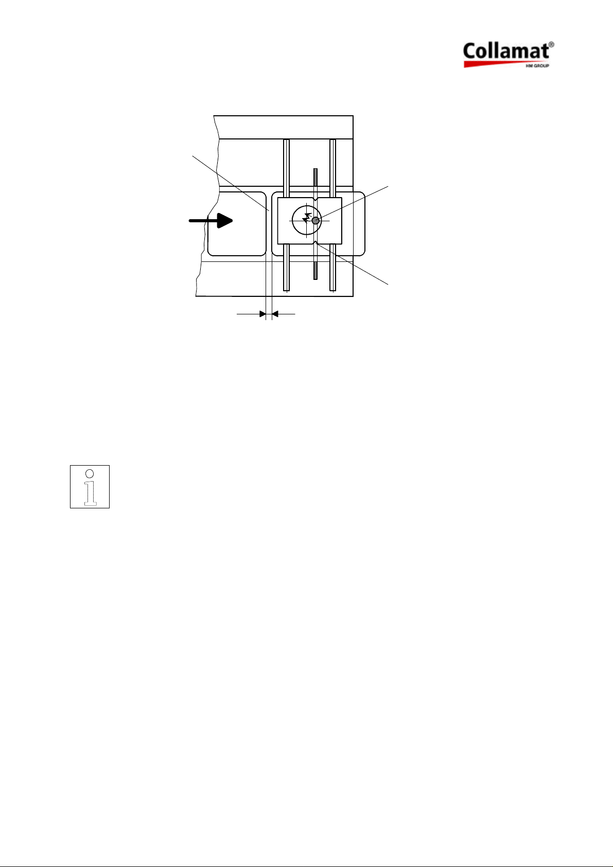
3.3 Adjustment of the optical label scanner
Gitter
min. 2 mm
Figure 9
Proceeding of the adjustment of the optical label scanner:
LED
1
Switch on the Collamat 3600. Set the label scanner potentiometer to zero. Pull the labelweb so
that the gap is located below the marking 1 of the scanner. Turn the potentiometer until the red
LED on the scanner goes off. Continue pulling the labelweb until a label is located below the
scanner. Continue turning the potentiometer until the LED switches off again. The optimum
setting is at the center position of the two potentiometer settings witch turned the LED off.
Remark:
If the setting of the optical label scanner is faulty, the gap between the labels
will not be detected. After the triggering of a labelling operation, the labeler
will stop after approx. 0.75 m of the labelweb.
For transparent labels, please use the mechanical label scanner.
5999.515-01E 12.06.2007 WM Page 12 / 47
Page 14
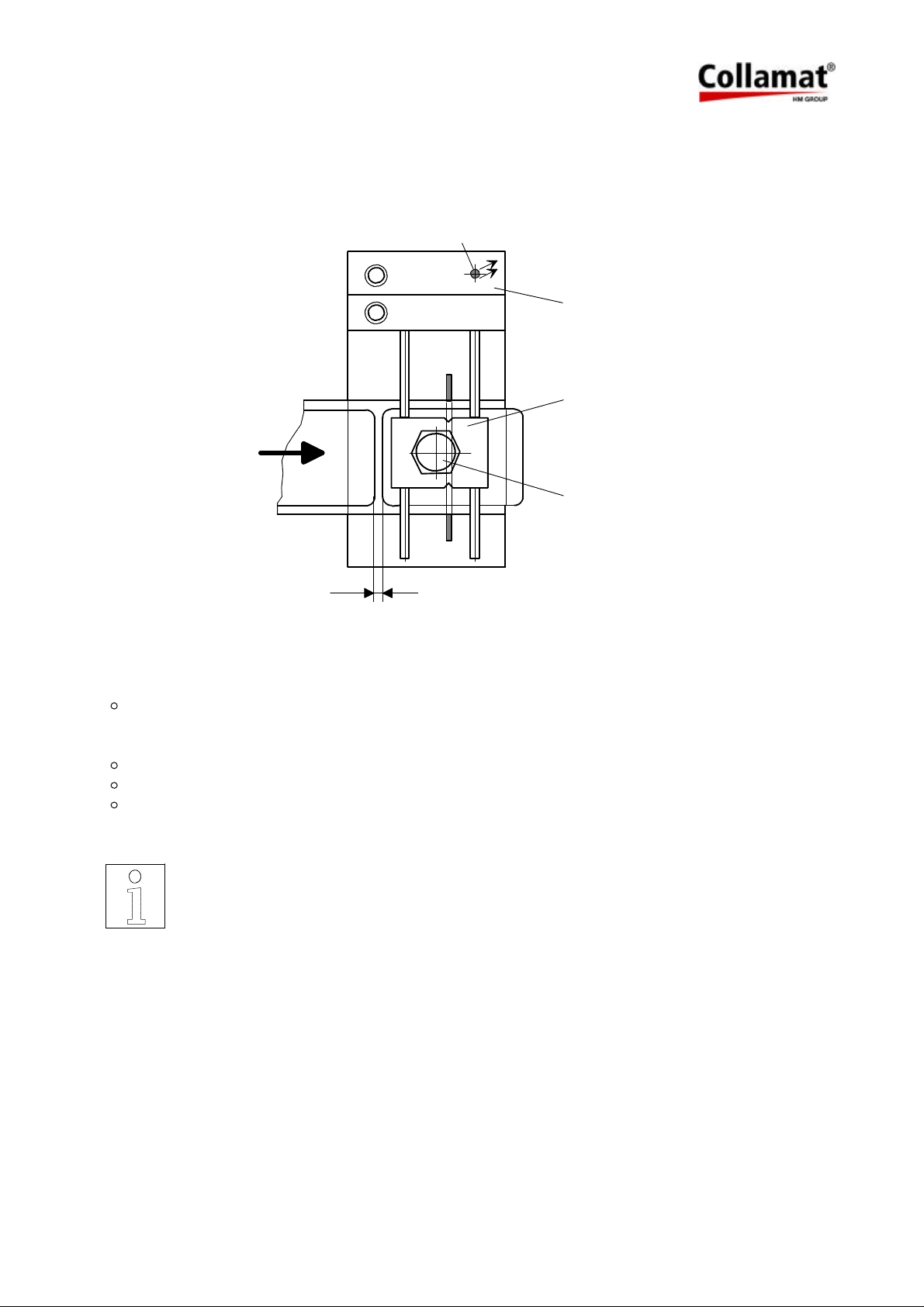
3.4 Adjustment of the mechanical label scanner
The mechanical label scanner (not used on magnetic flap adapter) is an alternative to the optical label scanner and is mainly used for transparent labels.
LED
1
1
2
2
3
3
2 - 6 mm
Figure 10
Adjustment:
Place the label under the scanning head, the LED on the scanner support must be turned
on. If this is not the case, unscrew the nut on the scanning head and turn it counterclock-
wise until the LED turns on.
Turn the scanning head clockwise until the LED turns off.
Turn the scanner one quarter turn forward and retight the nut.
Place the gap between the labels under scanning head, the LED-display must be turned
on.
1. Scanner support
2. Scanning head
3. Nut
Note:
No adjustment is necessary on the traction unit!
5999.515-01E 12.06.2007 WM Page 13 / 47
Page 15
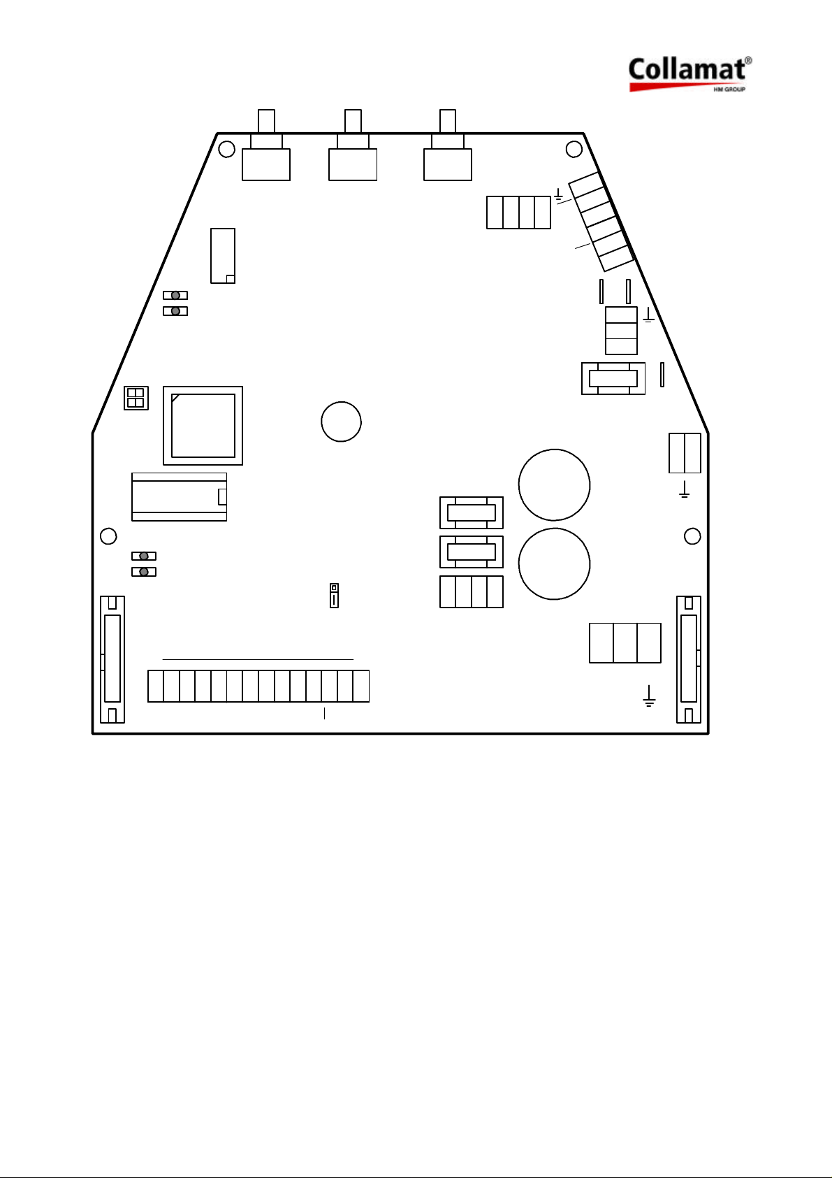
4 Technical description
4.1 Dispenser board
All the electronic devices including power transformer, except of the main switch with indicator
lamp, are located on a printed board. The dimensions of the board are approximately 215 x
234 mm. Figure 11 shows the board with all the connectors and terminals.
The description is divided into power supply, motordriver, controller and firmware.
4.1.1 Power supply
The power supply unit generates the two regulated voltages +12 V/1A and + 5 V/1 A for the
logic, as well as an unregulated DC voltage of approx. 40 V/3.5 A for the steppermotor. The
stabilization is done by linear voltage regulators.
4.1.2 Motordriver
The driver board consists of 2 H-bridge circuits to drive the two motor phases. The phase current is 4 A while running, and 2 A when stopped. To control the current, a chopper circuit with
20 kHz chopper-frequency is used.
Dependent on the dispensing speed the processor generates a fullstep- or a halfsteppattern.
For speeds faster than 10 m/min, the motor is driven by a fullstep- pattern.
In the case of overheating, short-circuit or malfunction the motordriver is switched off and the
red LED FAULT is illuminated. In this case the labeler must be switched off and on again.
4.1.3 Controller
The single chip micro-controller H8/532 with external 32 K-Byte EPROM controls the functions
of the labelling process.
All outputs are buffered by photo-couplers.
All the inputs are pulled up to +12V with 2.2 K and are equipped with a low-pass filter.
The A/D-converter scans periodically the value of the settings of the 3 potentiometers
(R101....R103).
The control current of the label scanner is generated by a controlled current source.
5999.515-01E 12.06.2007 WM Page 14 / 47
Page 16
TEST
RESET
X104
2
FAULT
SPEED PREDISP TCY
1
7605
a3
2AT 230V
4AT 115V
X48
a2
a1
L1
N1 X46
F1
9
OUT
6
N
L
1
DIR
IC2
5V
12V
X105
X1
GND
GSC1
+12V
GND
LSC
+12V
TCY
+12V
GND
RDY
FEED
IFD
IFD
X14
+12V
Figure 11: Dispenser board
4.2 Signals and connection diagrams
F2
3.15AT
X36
3 3
X51
F3
1.6AT
X101X102
X39
7
7
IN
X40
L
N
PE
All in- and outputs are equipped with filter elements to prevent electromagnetic interference.
These components also prevent interference caused by electrostatic discharge. The interference can lead to malfunction of the Collamat 3600. Anyway, installing the Collamat 3600 you
have to consider the rules concerning RMI and ESD to prevent these interferences. See also
chapter Cabling.
5999.515-01E 12.06.2007 WM Page 15 / 47
Page 17
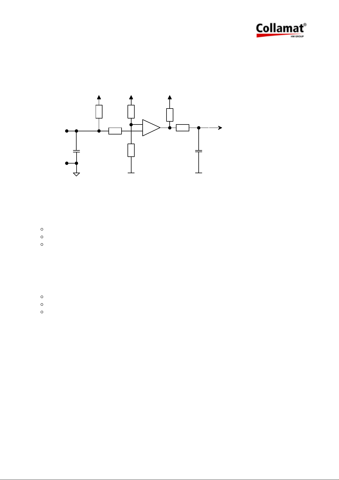
4.2.1 Inputs
The inputs are used to connect peripheral units and sensors. The inputs are activated while
they are pulled to GND (0 Volt). The peripheral units from Collamat Stralfors AG have NPNoutputs to 0 Volt.
Figure 12 shows the schematic diagram of the inputs:
+5 V
2k2
H8/532 Input
4k7
10nF
On: >4mA (or < 2 V)
IN
GND
1n
2k2
100k
+12 V+12 V
10k
+
LM339
10k
Off: 0mA (or > 8 V)
Vmax: 24 V
Figure 12: Signal input
An input is then active, when a current of minimum 4mA is pulled to GND. The following inputs
are available:
GSC1 Goods scanner
LSC Label scanner
READY READY-signal for peripheral units
4.2.2 Outputs
The outputs are used to control peripheral units. There are three different kinds of outputs:
Isolated output
Open-Collector-output
Currentsource-output
5999.515-01E 12.06.2007 WM Page 16 / 47
Page 18
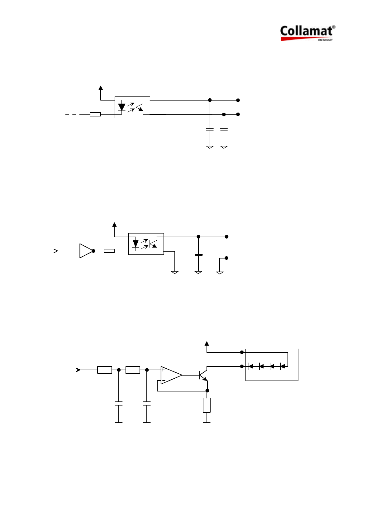
4.2.3 Isolated output IFEED
This output is completely isolated to the electronic circuit of the labeler. Figure 13 shows the
schematic diagram of this isolated output:
+5 V
+
Umax.: 24 VDC
Imax: 25 mA
-
PC355T
1n
1n
Figure 13: Isolated output IFEED
4.2.4 Open-Collector-output IFEED
For better resistance against interferences, the Open-Collector-output IFEED is also equipped
with a photocoupler. Figure 14 shows the schematic diagram of the Open-Collector-output
IFEED:
+5 V
+
Umax.: 24 VDC
Imax: 25 mA
PC355T
1n
Figure 14: Open-Collector-outputs
4.2.5 Currentsource-output
For the IR-transmitter of the label scanner TCY, a controlled currentsource is used. Figure 15
shows the schematic diagram of the currentsource:
+12 V
OP-AMP
LM358
100
TCY
BCP54-16
4 IR-LEDs
PWM
H8/532
10k 100k
100n 10n
Figure 15: TCY-currentsource
5999.515-01E 12.06.2007 WM Page 17 / 47
Page 19
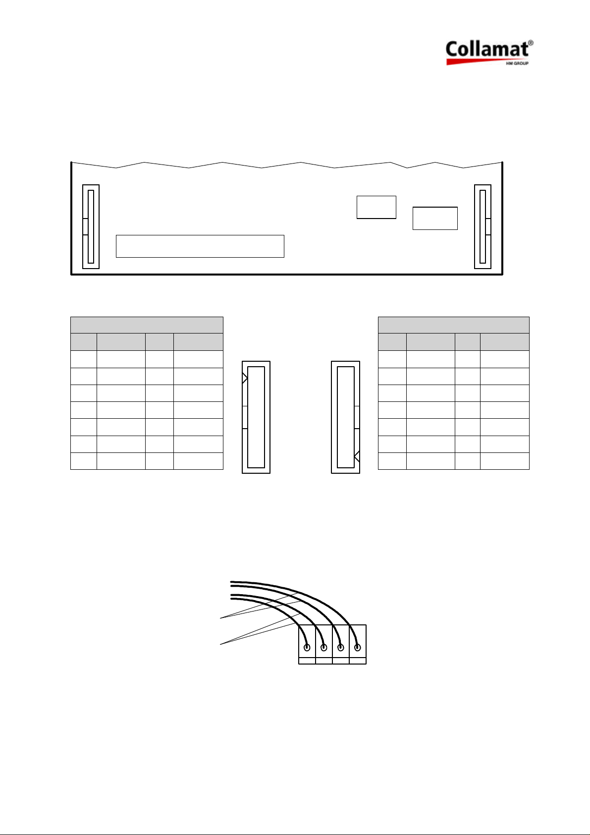
4.3 Connection diagrams BUS X101, X102
The buscable of the peripheral units is connected to the connectors X101 or X102. The cable
must be placed inside of the module rail to prevent interferences. Figure 16 shows the position
of the buscable connectors on the dispenser board:
X102
X101
1
1
Figure 16
Connector X102 Connector X101
Pin Signal Pin Signal Pin Signal Pin Signal
1 +12V 2 +12V 1 GND 2 GND
3 READY 4 FEED 3 nc. 4 nc.
5 LSC 6 GSC1 5 nc. 6 nc.
7 TCY 8 nc. 7 nc. 8 TCY
9 nc. 10 nc. 9 GSC1 10 LSC
11 nc. 12 nc. 11 FEED 12 READY
13 GND 14 GND 13 +12V 14 +12V
1 2
13
14
14 13
12
4.4 Transformer wiring
The secondary side of the transformer is connected to the terminals X36...X39. Both violet
wires are connected to the terminals signaled with a 7. Both orange wires are connected to the
terminals signaled with a 3. See also Figure 17:
violett
orange
X36
3 3
7
Figure 17
5999.515-01E 12.06.2007 WM Page 18 / 47
X39
7
Page 20
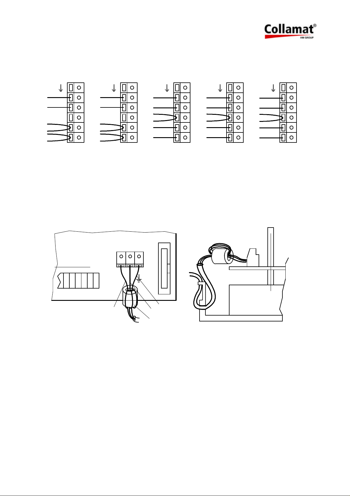
The primary side of the transformer is connected to the terminals X46 and X48. Dependent to
the mains voltage the transformer is connected as shown in figure 18:
110 V 120 V
X48
9
a3
a2
5
a1
8
L1
4
2
N1
0
0 = schwarz 2 = rot 4 = gelb 5 = grün
X46
0
2
8
4
9
5
a3
a2
a1
L1
N1
X48
9
5
2
4
8
0
X46
220 V 230 V 240 V
a3
a2
a1
L1
N1
X48
0
5
2
4
8
9
X46
X48
a3
a2
a1
L1
N1
X46
8 = grau 9 = weiss
a3
0
a2
2
5
a1
4
L1
8
N1
9
Figure 18: Transformer wiring
4.5 Connection of the mains input
The powercord must be connected to the terminal X40. To prevent interferences it must be
looped through a ferrite-filter as shown in figure 19:
X101
2 Windungen
X48
X46
IN
X40
X25
L N
PE
gelb/grün
braun
blau
Ferrit-Filter
Figure 19
4.6 Grounding of the labeler
The grounding of the module rail and of the adapter must be done to terminal X51. For this see
also figure 21.
5999.515-01E 12.06.2007 WM Page 19 / 47
Page 21
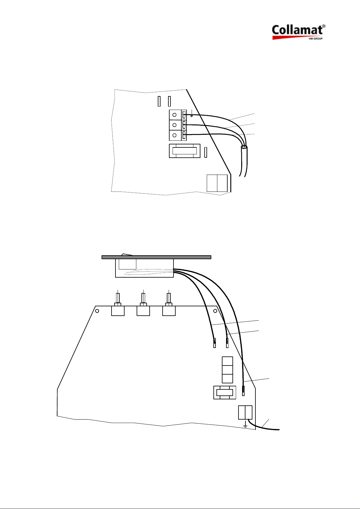
4.7 Connection of the mains output
Peripheral units like the flatprinter or the adapter with magnet are connected to the mains output. To this terminal only units, certified by Collamat Stralfors AG, may be connected. Figure
20 shows the mains output terminal:
9
6
X41
gelb/grün
OUT
F1
Figure 20
4.8 Connection of the frontpanel
The frontpanel must be connected as shown in figure 21:
N
L
blau
braun
1
X51
braun/weiss
blau
9
6
X41
OUT
F1
L N
1
X51
braun
gelb/grün
Figure 21
5999.515-01E 12.06.2007 WM Page 20 / 47
Page 22
4.9 Motor and motorcable
Attention:
The motor never must be dismantled !
Steppermotor heats up during operation !
When connecting or disconnecting the motor, the labeler must be switched
off !
While working on the motor, the labeler must be disconnected from mains !
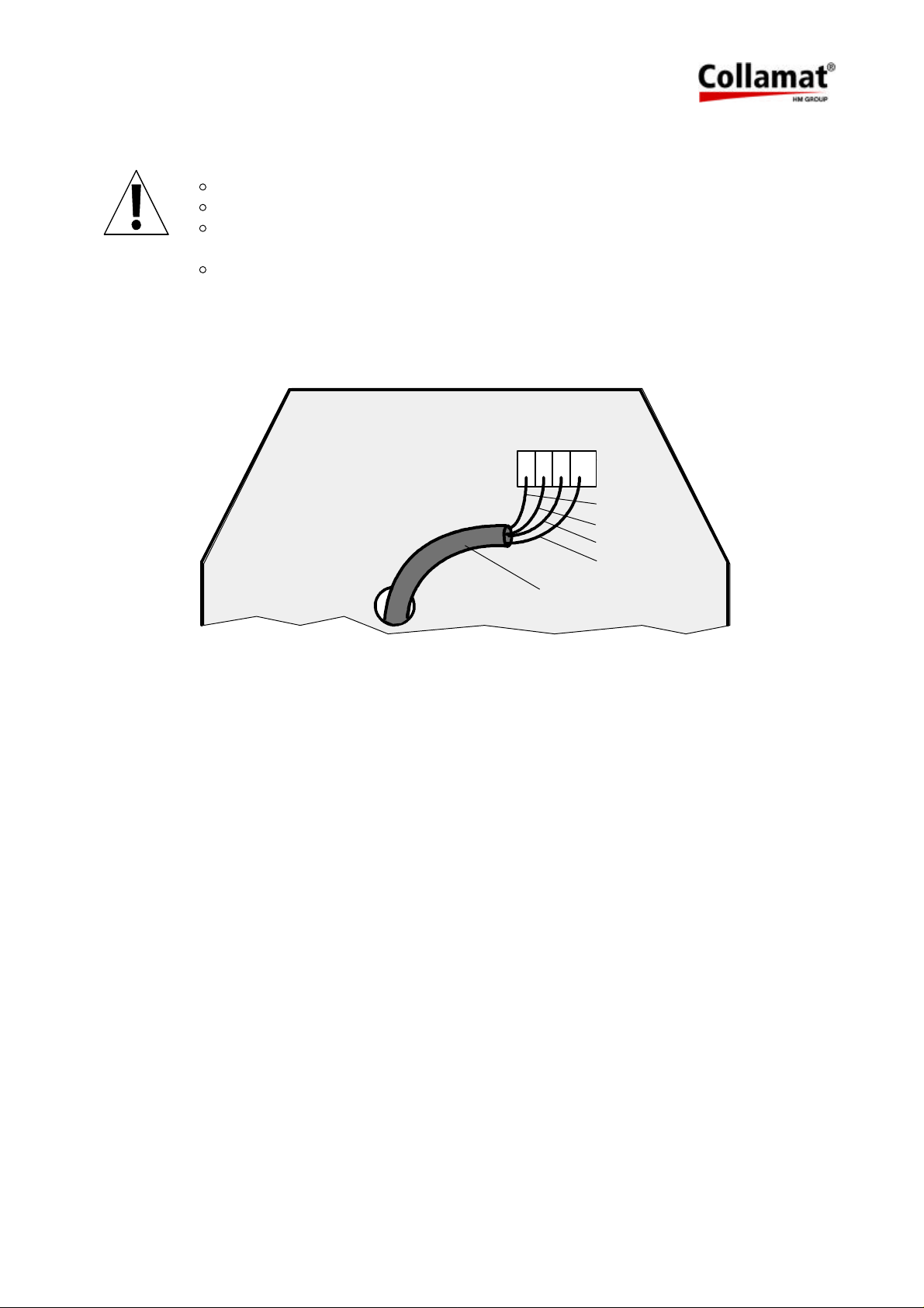
The motor is connected inside of the labeler. The motorcable is lead through the hole in the
middle part of the board. The wires are connected to the terminals X30...X33. See also figure
22:
X32
X30
506
7
Figure 22: Motor connection
X33
motorcable
X31
green
black
blue
violet
5999.515-01E 12.06.2007 WM Page 21 / 47
Page 23
5 Firmware
5.1 Normalmode
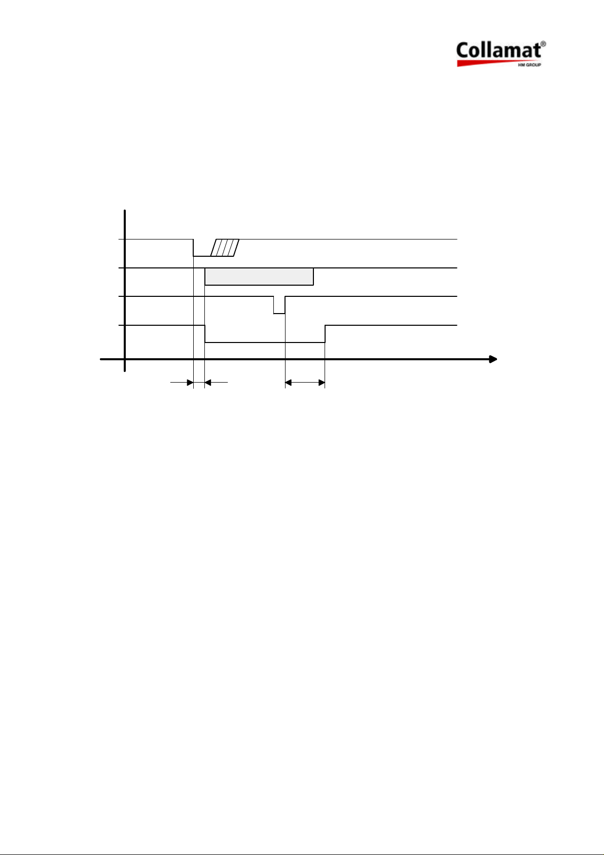
After turning on the labeler, the DIL-switches are scanned to figure out the working mode.
The dispensing of a label is triggered by the negative edge of GSC1 (Goods scanner input).
READY must not be active (12 Volt). The stop of the labelling is triggered by the detection of
the gap (LSC) and performing the remaining steps for the predispensing.
The timing diagram of the signals is shown in figure 23:
Signal
GSC1
Clock
LSC
FEED
1 2
t
Figure 23: Timing diagram of the GSC1, LSC and FEED signals
1. Speed dependent position delay
2. Length of the predispensing
If the predispensing is increased, it is executed immediately. If it is reduced, it is executed after
dispensing the next label.
To generate the holding torque, the motor is powered all the time.
If, for any reason, no negative edge is detected on the LSC-input, the labelweb is automatically
stopped after approximately 2 meters.
At speeds faster than 10 m/min, the steppermotor is driven in the fullstep-mode. For slower
speeds, in the halfstep-mode.
The minimum speed is 3 m/min. The maximum speed is 20 m/min.
5999.515-01E 12.06.2007 WM Page 22 / 47
Page 24
5.2 DIL-switches
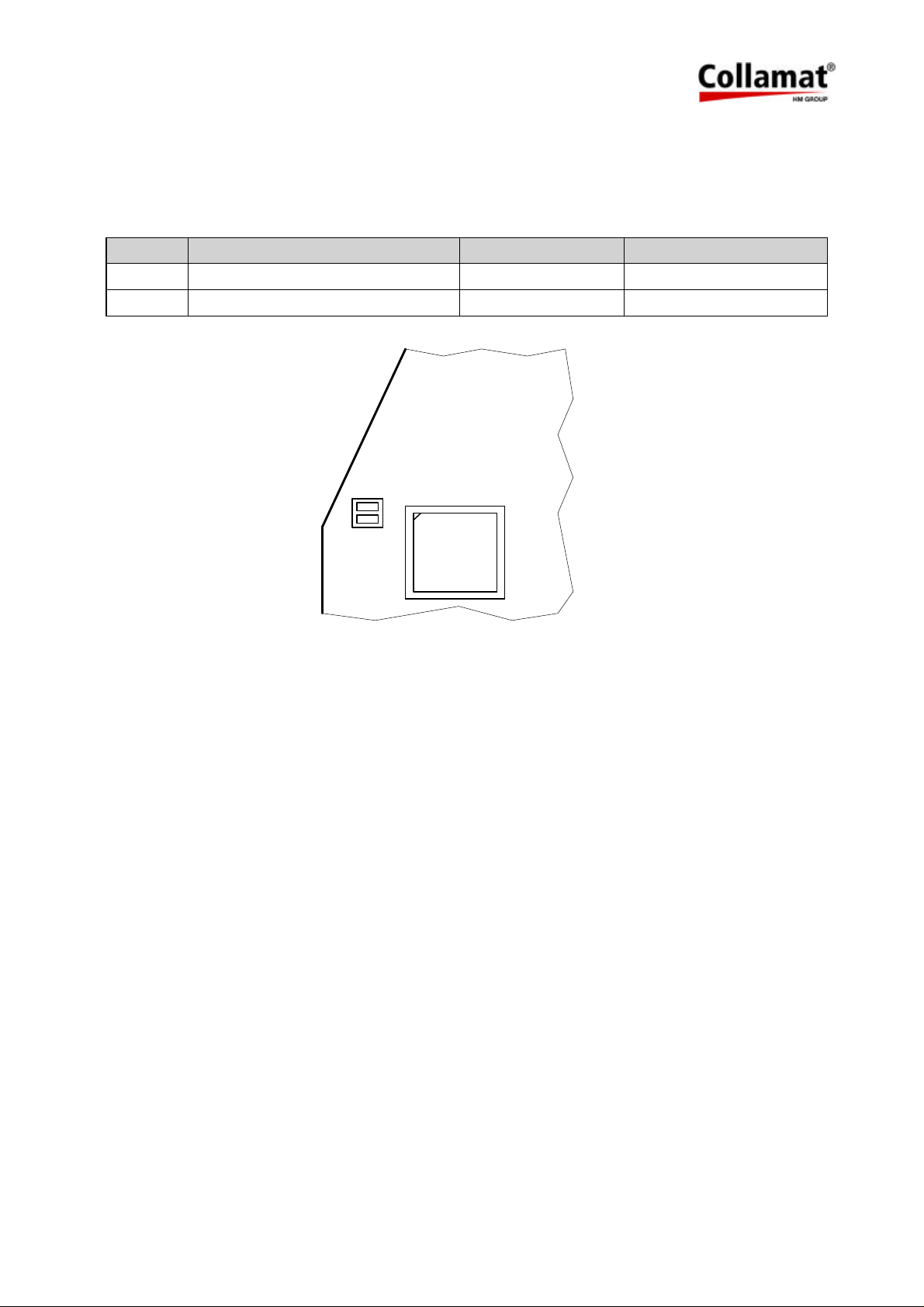
The dispenser board contains two DIL-switches. These switches are used to select different
operating modes. The following table and figure 24 show the functions and the positions of the
DIL-switches:
Switch Function Off On
TEST Labelingmode/ Testmode Labelingmode Testmode
DIR Turning direction of the motor Right Left
TEST
DIR
Aus
Ein
Figure 24: DIL-switches
5.2.1 DIL-switch TEST
This DIL-switch selects the testmode. For further informations to the testmode, please read the
chapter Testmode.
5.2.2 DIL-switch DIR
This DIL-switch selects the turning direction (right or left) of the traction motor.
5999.515-01E 12.06.2007 WM Page 23 / 47
Page 25
6 Trouble shooting
6.1 Fuses
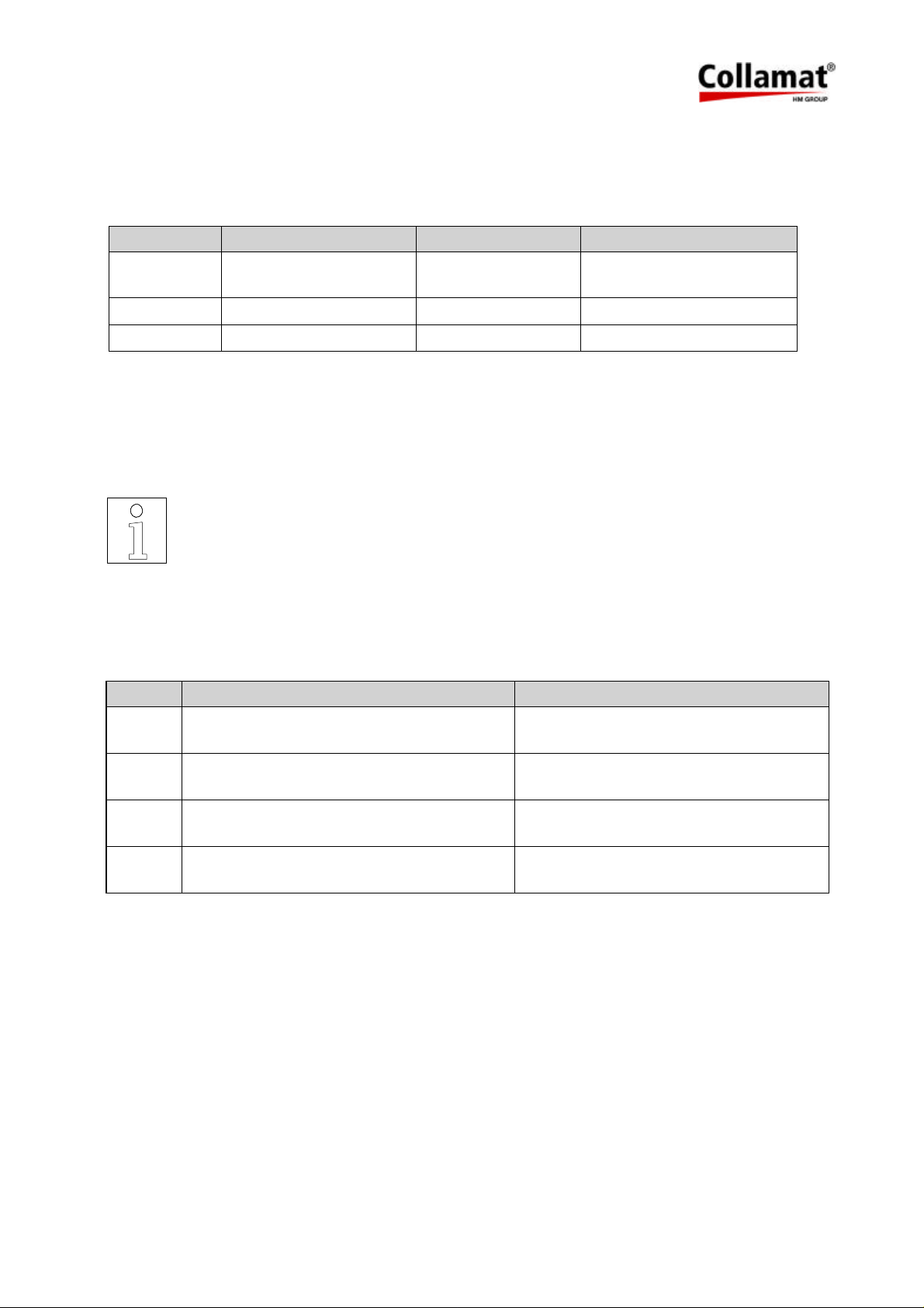
The Collamat 3600 contains three fuses:
Fuse Voltage Value Part. No.
F1 110V:
230V:
F2 Motordriver 40V 3.15AT 5*20mm 74031216
F3 Logic 12 V, 5V 1.6AT 5*20mm 74031135
To exchange the fuses, the cover of the Collamat 3600 must be removed.
If the fuse of the main voltage is blown, the indicator lamp of the power switch is not illuminated
when the Collamat 3600 is switched on.
If an external peripheral unit like flatprinter or flap adapter is working without any movement of
the traction motor, F2 seems to be defective.
Mains voltage 4AT 5*20mm
2AT 5*20mm
ATTENTION:
If the dispenser board is defective, it must be exchanged. Any repairs or
modifications not made by Collamat Stralfors AG will expire the guarantee.
74030800
74030341
6.2 Status LEDs
The four status LEDs on the dispenser board display show different signals:
LED Function Fault
5V Illuminated, when the 5V for the logic cir-
cuit are OK
12V Illuminated, when the 12V for the sensors
are OK
RESET Flashes while turning power on
Flash while running
FAULT Motordriver supervision Overheating, short circuit, undervoltage,
For trouble shooting, please use the checklist on the last page of the handbook.
Fuse F3 or F1
Fuse F3 or F1
Short circuit in the sensor supply
Watchdog RESET
Software failure
fuse F2
5999.515-01E 12.06.2007 WM Page 24 / 47
Page 26
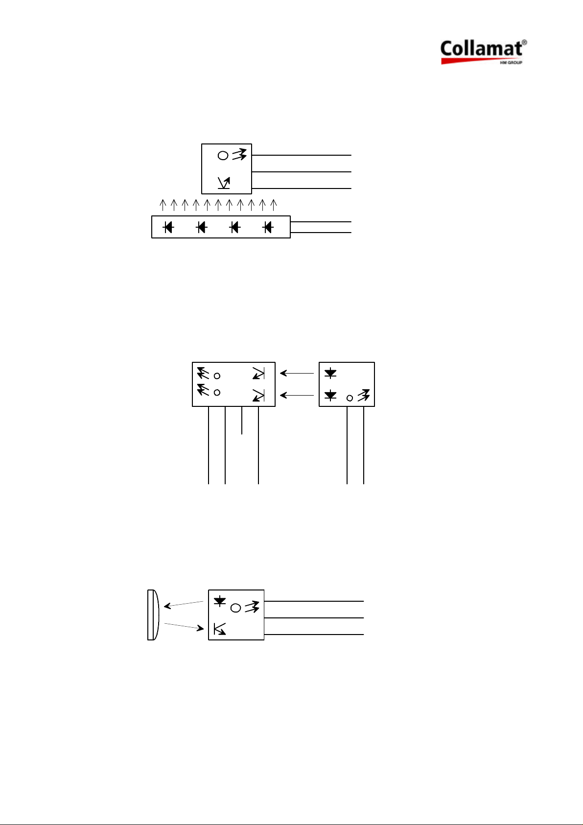
7 Peripheral units and sensors
7.1 Optical label scanner
Figure 25
7.2 Goods scanners
7.2.1 CS measuring IR-scanner
LEDs
1 9 4 5
5
9
1
5
1
+12 V
LSC
(LABELSCANNER)
GND
+12 V
TCY
(TRANSPARENCY)
LED
1 5
GND
Figure 26
7.2.2 NPN-Reflective scanner
Figure 27
GSC1
NPN
+12V
GND
+12 V
GSC1
GND
+12V
GOODSCANNER
5999.515-01E 12.06.2007 WM Page 25 / 47
Page 27
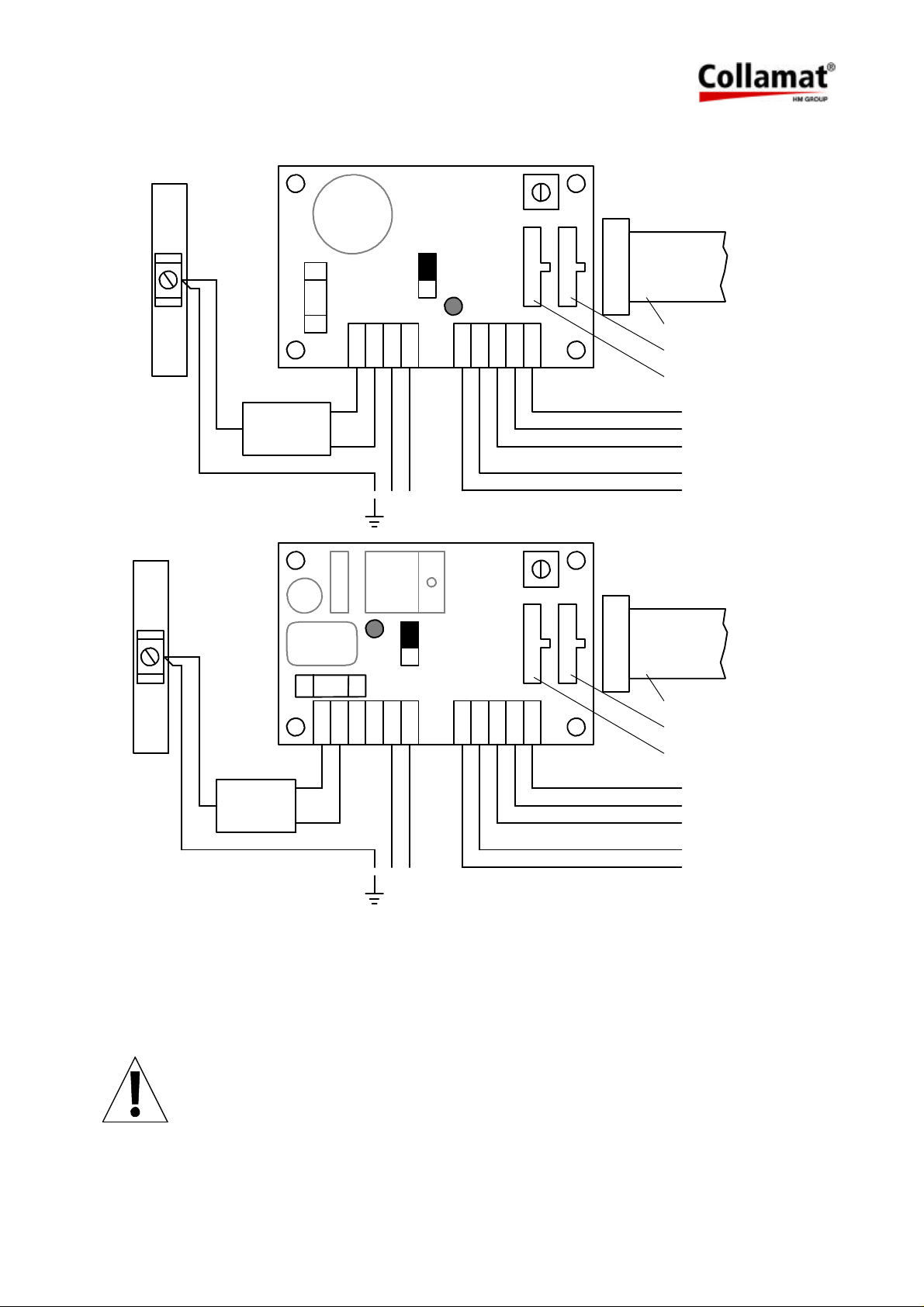
7.3 Magnet adapter
GS070C
GS070D
MAGNET
F1
3,15AT
MAGN
ON
OFF
220V
MAGN
N
Ph
220V
LED
TIME
TCY
+12V
DELAY
LSC
GND
L R
+12V
14 Pol
FLACHKABEL
RECHTS
LINKS
+12 V
LSC
GND
+12V
TCY
ON
LED
OFF
14 Pol
F1
GND
+12V
L R
LSC
+12V
FLACHKABEL
RECHTS
LINKS
+12 V
LSC
GND
+12V
TCY
MAGNET
MAGN
MAGN
3,15AT
220V
CP21
CP21
Ph N
220V
TCY
Figure 28
The mains voltage must be connected inside of the flap printer or inside of the dispenser.
The factory setting of the trimmer TIME is on MINIMUM. The trimmer is used to set a delaytime
for the releasing of the magnet.
The terminals CP21 are used to connect the synchronous motor of the wrap around adapter
WARNING:
Plugging in of the LEFT or RIGHT connector of the flatcable to the wrong plug
can damage the magnet adapter board.
5999.515-01E 12.06.2007 WM Page 26 / 47
Page 28
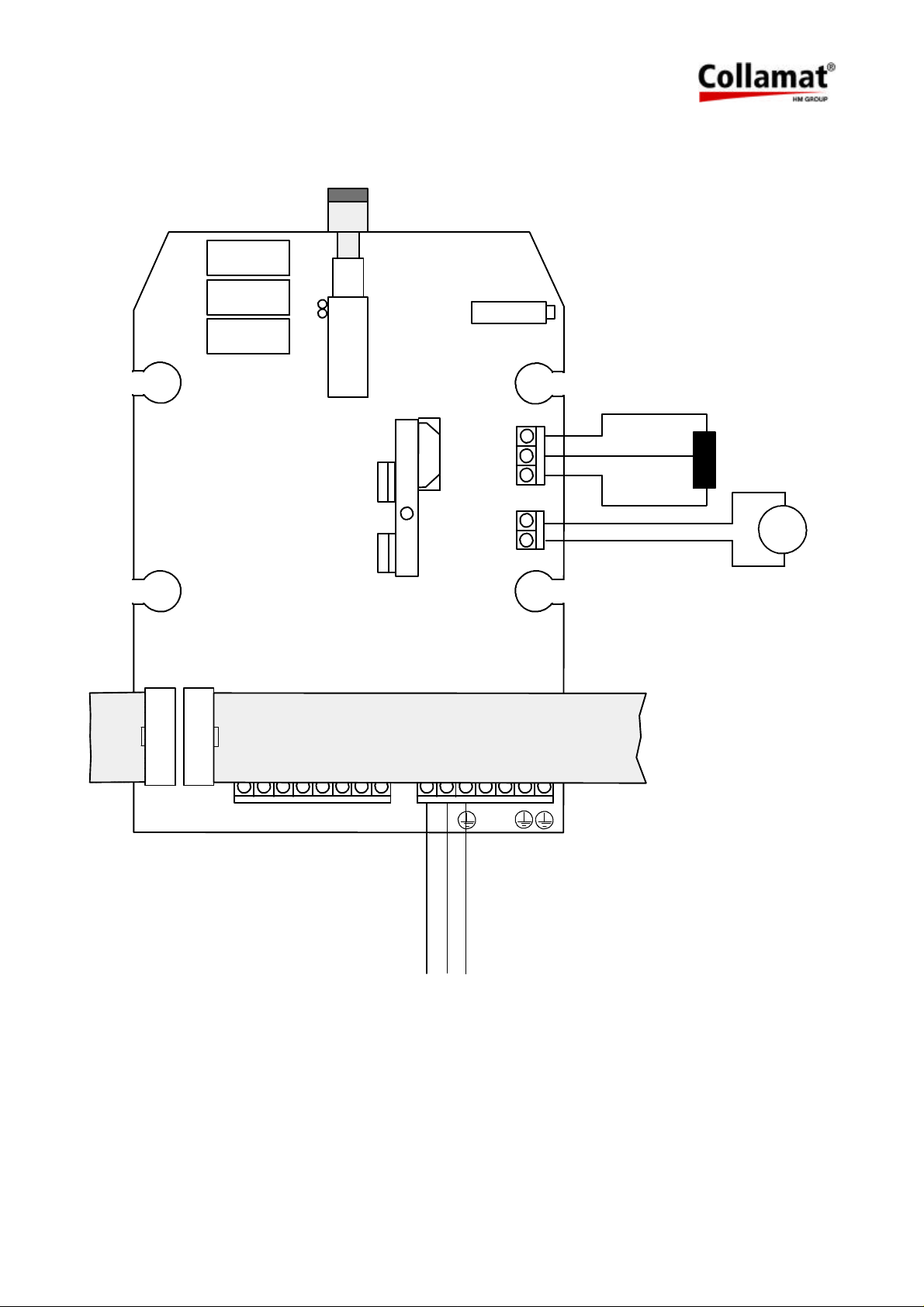
7.4 Flatprinting unit
7.4.1 Flatprinter board
S1
P1
X5 X6
Collamat Buskabel 14 polig
Collamat Buscable 14 poles
12v
12v
/IFEED
IFEED
/TCY
GND
GND
/LSC
X3
1
2
3
1
2
rot / red
rot, schwarz
red, black
schwarz / black
braun / brown
weiss / white
M
X4
Farbbandmotor
Ribbonmotor
L N
N
L
braun / brown
gelb,grün
yellow,green
blau / blue
Figure 29
5999.515-01E 12.06.2007 WM Page 27 / 47
Page 29
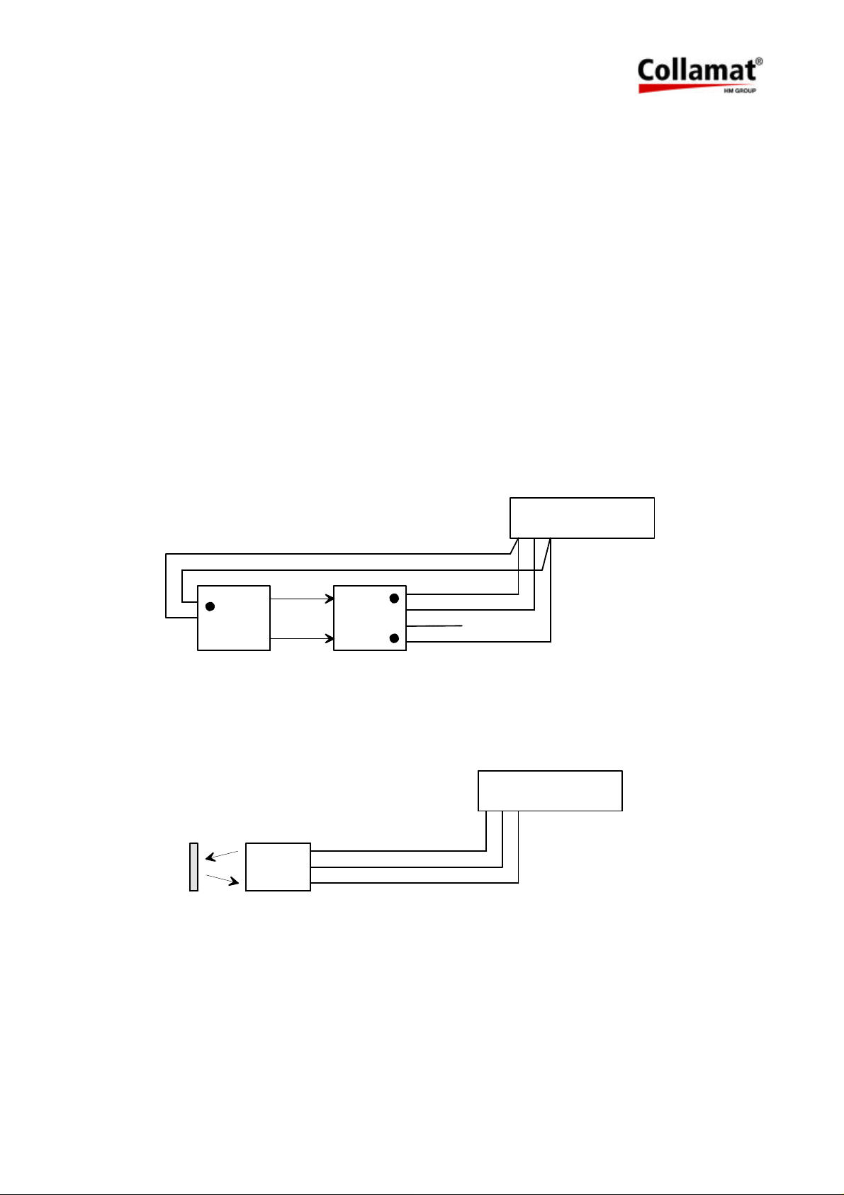
8 Control signals for external units
The signals FEED and READY are used to control external units.
FEED (Output)
The FEED signal indicates that the labeler is dispensing. This means that the steppermotor is
turning. With this signal an external flatprinting unit can be controlled. See herefore figure 23.
READY (Input)
The signal READY is used to signal that a connected peripheral device like hotstamp or flatprinter is ready. If the signal is active, this means the NPN-output of the device is pulled to
GND, labelling is not possible.
8.1 How to connect a goods scanner
The goods scanner is connected to the GSC1 terminals. Figure 30 shows the connection of the
standard Collamat Stralfors AG IR goods scanner:
LSC
TCY
+12V
GND
+12V
IR
brn
grn
brn
wht
yel
grn
GND
+12V
GND
GSC1
+12V
GND
GSC1
GND
+12V
Figure 30: Connection of the CS IR goods scanner
Figure 31 shows the connection of a NPN-scanner:
GND
NPN
GSC1
+12 V
Figure 31: Connection of a NPN-scanner
GND
GSC1
GND
+12V
LSC
TCY
+12V
GND
+12V
5999.515-01E 12.06.2007 WM Page 28 / 47
Page 30

9 Electrical installation
9.1 Introduction
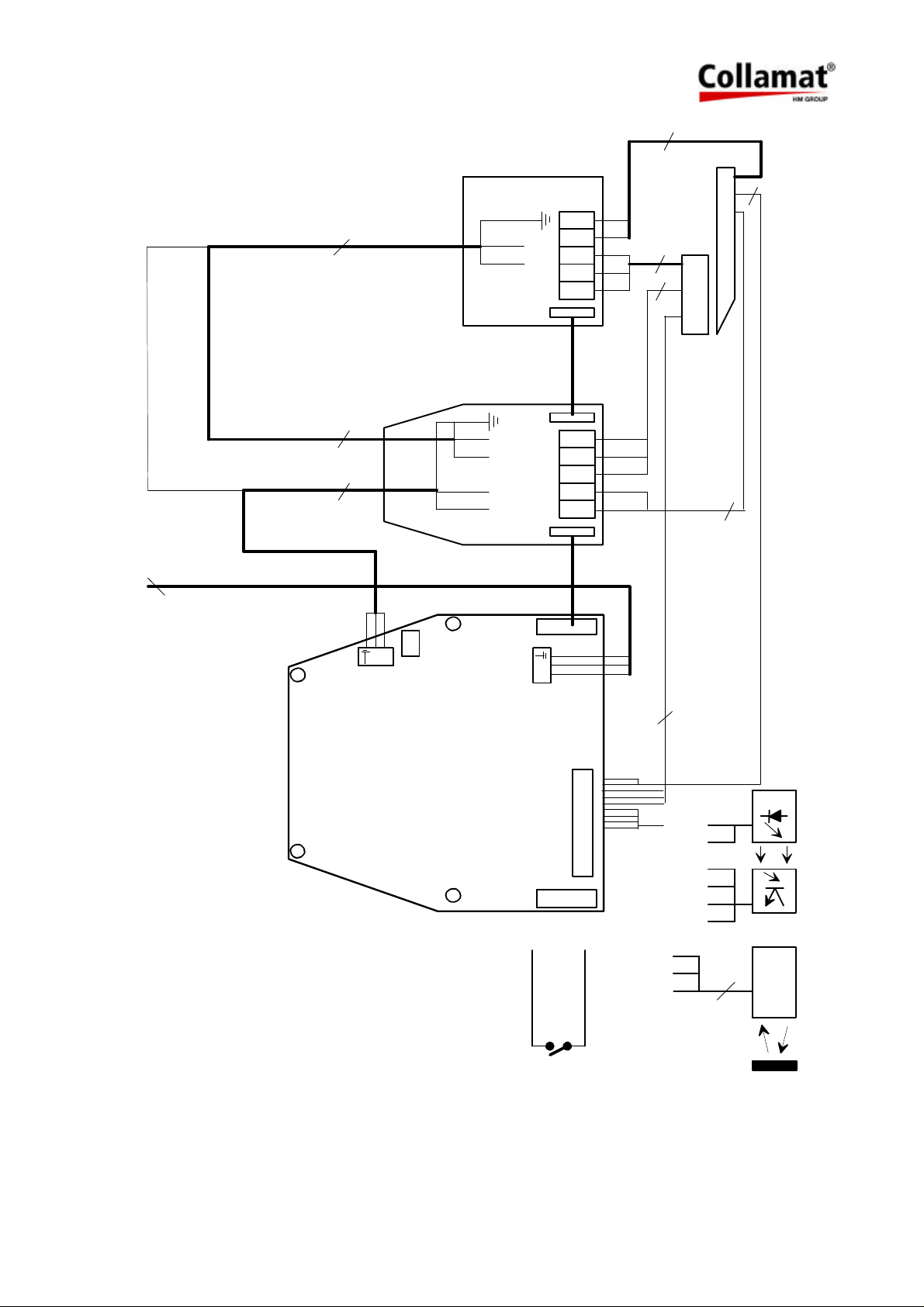
The cabling must be done like shown in figure 32. The controlsignals FEED and READY, the
supply +12 Volt and ground, are fed through the 14 pole flatcable to the flatprinter and the
magnet adapter. An additional 3 pole power cable (3 x 0.75 mm2) feeds the switched mains
voltage from the Collamat 3600 to both peripheral units.
The transmitter (2 pole cable) and receiver (3 pole cable) of the optical label scanner can directly be connected to the dispenser C3600, to the flap adapter or to the flatprinter respectively. In this case, the connection to the Collamat 3600 is made by the 14 pole flatcable.
5999.515-01E 12.06.2007 WM Page 29 / 47
Page 31
2
2
3
50/60Hz
POWER SUPPLY
110/230V
POWER SUPPLY
from flat printer
110/230V
3
3
3
6
4/5
N
FLAP
ADAPTER
4/5
1 6
P1/P2
P8
P7
P6
95
1
3
9
P5
P4
3
5
OPTICAL LABEL SCANNER
4/5
1
L
6
1
6
1
P2P1
FLAT
PRINTER
X101
N
L
4/5
1
P4
P5
P2
P3
P1
6
3
2
DISPENSER
151945
GND
+12V
GND
GSC1
X102
GSC1
GND
Micro-switch
GND
GSC1
+12V
+12V
NPN
3
G&S IR Goods scanner
Reflex scanner
Figure 32: Connection diagram
5999.515-01E 12.06.2007 WM Page 30 / 47
Page 32
10 Testmode
The firmware of the Collamat 3600 has a standard test and diagnostic routine. If the DIL-switch
TEST is switched on while turning the power on, the firmware starts the test and diagnostics
routine. See also figure 24.
In the testmode, the motor is started and stopped periodically with the speed, set on the
SPEED potentiometer. If there are any labels threaded through the Collamat 3600, the labels
will be dispensed periodically.
In the testmode, the Collamat 3600 can be controlled by an ASCII-terminal or a PC with a terminal emulation software. The communication with the Collamat will be done through the connector X104 using the RS232 protocol. The test software is menu driven and self explaining.
The user language is English.
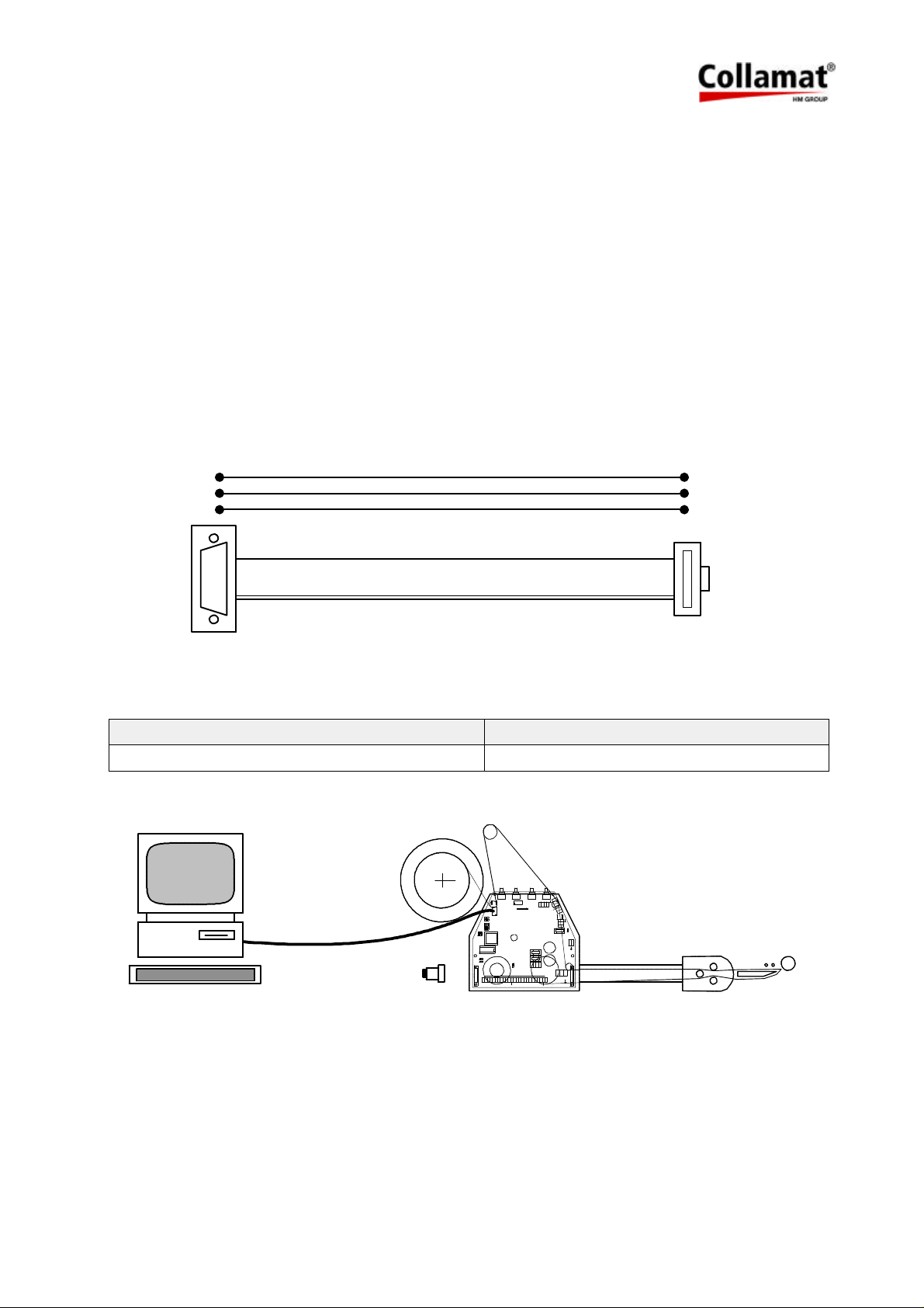
To communicate with a PC, a serial communication cable is used. The figure 33 shows the
electrical connections of the serial cable:
9Pol D-Sub
2
3
5
10 pol
1
Figure 33
Communication parameters Terminal settings
9600 Baud, 8 Bit, 1 Stop Bit, No Parity TTY, Text
Figure 34 shows how to connect the Collamat 3600 to a PC:
PC
COM1
Diagnosestecker
RESET
FAULT
DEL
NS
R1
R2
TEST
DIR
5V
12V
X1
GND
GSC1
SPEED PREDISP POS TCY
X61
X60
X104
1
2
LSC
GND
TCY
+12V
+12V
+12V
X48
7605
X103
a3
1
a2
X106
a1
1
L1
N1 X46
9
6
N
OUT
L
F1
2AT 230V
1
4AT 115V
X51
F2
2.5AT
F3
1.6AT
X101X102
X36
X39
3
7
3
7
X105
IN
X40
X25
L N
IFD
IFD
GND
RDY
FEED
PE
GND
GND
GND
ERR
ERR
+12V
+12V
+12V
GSC2
GSC3
NSTPI
NSTPO
10Pol Flachkabel
3
5
9
1
Figure 34: Test connections
5999.515-01E 12.06.2007 WM Page 31 / 47
Page 33
10.1 Test software
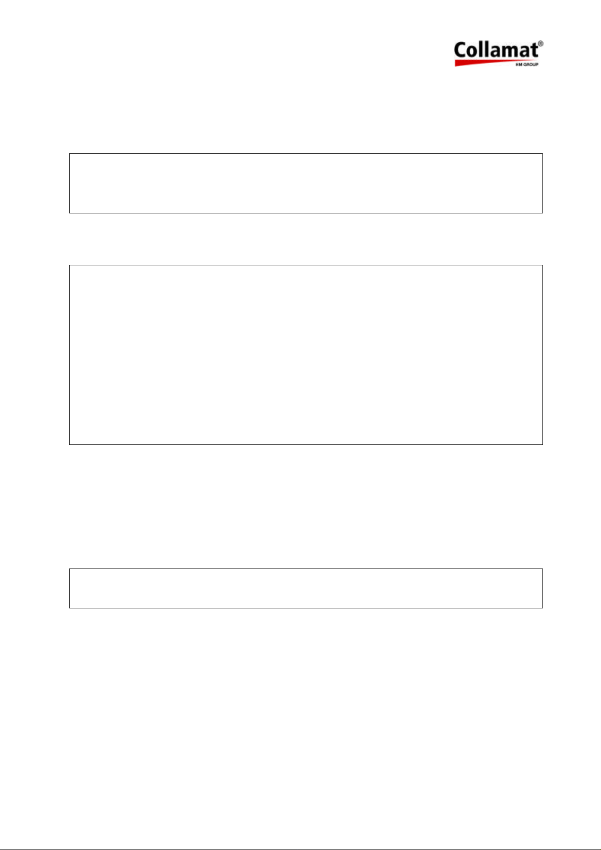
When the Collamat 3600 is connected to the terminal, it must be switched on. At this moment
the DIL-switch TEST must be set to on. The traction unit begins to turn with the speed set on
the SPEED potentiometer. The terminal shows the following message:
COLLAMAT 3600 V1.01
Motor intervall test. Use spacebar to leave
Pressing the spacebar stops the motor intervall test. Now the following help menue will be
displayed:
Helpmenue for C3600 Testprogram
------------------------------H : Help
M : Motortest
N : Motor intervall test
B : BUS-signal selftest
S : Signals display
D : DIL-switch settings
P : Potentiometer settings
V : Firmware Version
Select Testfunctions with the Keys H,M,N,B,S,D,P,V
>
The testfunctions can be called with the appropriate keys. All testfunctions can be stopped with
the spacebar.
10.1.1 Motortest
Motortest
The
the speed set on the SPEED potentiometer.
>m
Motortest. Use spacebar to leave
is used for measuring the phase currents of the motor. The motor turns with
5999.515-01E 12.06.2007 WM Page 32 / 47
Page 34
10.1.2 Motor intervall test
The Motor intervall test tests the labelling functions of the Collamat 3600. If a label web is
threaded through the dispenser, labels will be dispensed periodically with the speed set on the
SPEED potentiometer.
>n
Motor intervall test. Use spacebar to leave
10.1.3 BUS-signal selftest
The BUS-signal selftest tests all in- and outputs of the Collamat signalbus. For this test a
diagnostic connector (see figure 35) must be plugged into the busconnector X102 (left side).
Attention:
To avoid damage of peripheral units or sensors, all sensors and bus- cables
must be removed from the connectors.
>b
BUS-signal selftest
Testing FEED+LSC......OK
Testing FEED+READY....OK
Testing TCY+GSC1......OK
This test will display faulty signalpairs on the terminal screen. If the test is started without the
diagnostic connector the following message is displayed:
>b
BUS-signal selftest
Testing FEED+LSC......not OK !
Testing FEED+READY....not OK !
Testing TCY+GSC1......not OK !
5999.515-01E 12.06.2007 WM Page 33 / 47
Page 35
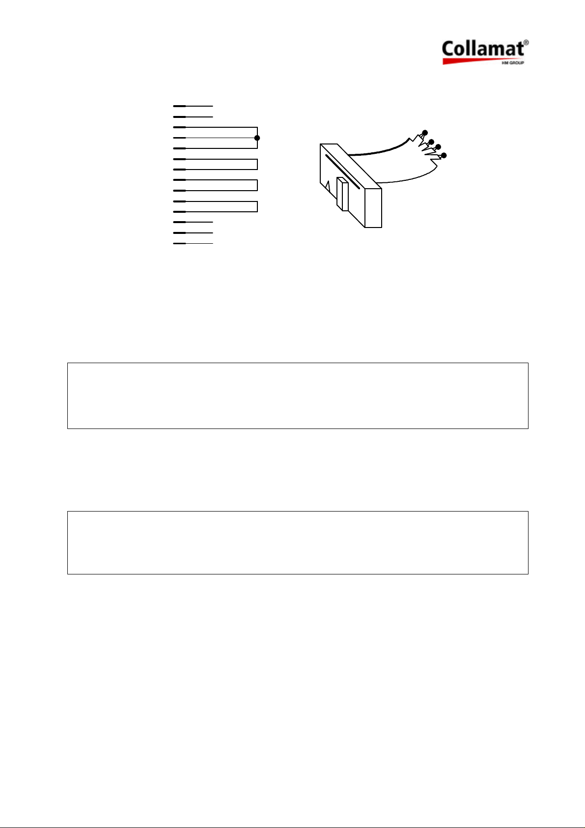
Figure 35 shows the schematic diagram of the diagnostic connector:
+12V
+12V
READY
FEED
LSC
GSC1
TCY
GSC2
RESOUT
CLK
RESIN
nc
GND
GND
1
2
3
4
5
6
7
8
9
10
11
12
13
14
nc
nc
1
1
14
14
nc
nc
nc
Figure 35: Diagnostic connector
10.1.4 Signal display
This test displays the levels of the input signals. It is used to test the function of the sensors
and input circuits.
>s
Signals display. Use spacebar to leave
GSC1 READY LSC FAULT
OFF OFF OFF OFF
10.1.5 DIL-switch settings
This test shows the position of the DIL-switches. It is used to test the function of the
DIL-switches.
>d
DIL-switch settings. Use spacebar to leave
TEST DIR
ON OFF
5999.515-01E 12.06.2007 WM Page 34 / 47
Page 36
10.1.6 Potentiometer settings
This test shows the position of the potentiometers. It is used to test the function of the
potentiometers.
>p
Potentiometer settings. Use spacebar to leave
SPEED PRE. TCY
0631 0057 0187
10.1.7 Firmware Version
This test displays the firmware version number and its release date.
>v
Firmware Version
COLLAMAT 3600
Version : V1.01
Date : 28. Nov. 1996
5999.515-01E 12.06.2007 WM Page 35 / 47
Page 37
11 Control of a hotstamp with the IFEED signal
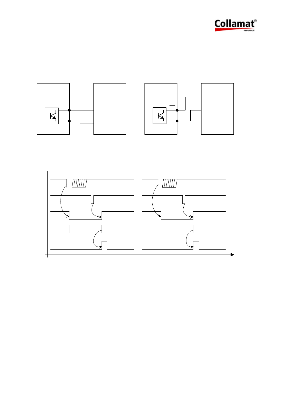
Two different type of hotstamps (NPN or PNP) can be connected. Figure 36 shows how to
connect different hotstamps. Figure 37 shows the timing diagram.
MONITOR
CONTROL SIGNALS
IFEED
IFD
+
IFD
-
HOTSTAMP
NPN-Input
+12V / +24V
NPN
GND
Figure 36: Connection of IFEED
GSC1
LSC
FEED
MONITOR
CONTROL SIGNALS
IFEED
IFD
+
IFD
-
HOTSTAMP
PNP-Input
+12V / +24V
PNP
GND
Umax: 24VDC
Imax: 25 mA
IFEED
IFEED normal IFEED invers
STAMP
T
Figure 37: Timing diagram
Dependent to the manufacturer and the model, the polarity of the triggering signal of the hot-
stamp must be changed. This adjustment is to be set with the jumper X105 on the dispenser
board, to normal or inverse. The position of the jumper X105 can be found on figure 11.
5999.515-01E 12.06.2007 WM Page 36 / 47
Page 38
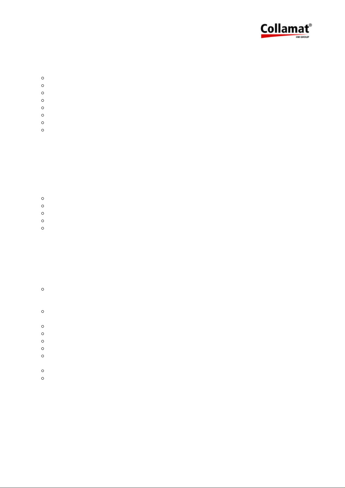
12 Cabling and setting up
For a trouble free operation of the Collamat 3600 following items must be observed:
Trained personnel
Ambient temperature
Absence of dirt and dust
Absence of splashing water
Installation and setting up of the installation
Installation and setting up of the Collamat 3600
Electromagnetic interferences
Safety regulations and safety requirements
12.1 Cabling
Electromagnetic interferences can lead to non repeatable and not obvious errors while labelling. Most times misplaced layout of the cabling, RMI and ESD interferences disturb the labelling. Because of this, the following rules must be observed for the cabling:
Separated mains and signal cables
Use shielded cables
All units must be grounded
Connect only devices which meet the RMI standards
Use power filters in interfered environments and interfered mains supplies
12.2 Setting up
The setting up must be done carefully by trained personnel. The following items must be
observed:
Visual check of the labeler unit
Are all electrical and mechanical units correctly attached ?
Are all connectors accessible ?
Connect the labeler to the mains and switch it on
Is the power switch illuminated ?
Turn off the labeler and unplug it
Set up the DIL-switches according to the desired mode. Motor turning direction.
Attach the goods scanner signals to the labeler
Connect the remaining units to the labeler
Connect the labeler to the mains and switch it on
Do the peripheral units work OK ?
Thread the paperweb and adjust the label scanner
Dispense a label. Is it dispensed correctly ?
5999.515-01E 12.06.2007 WM Page 37 / 47
Page 39
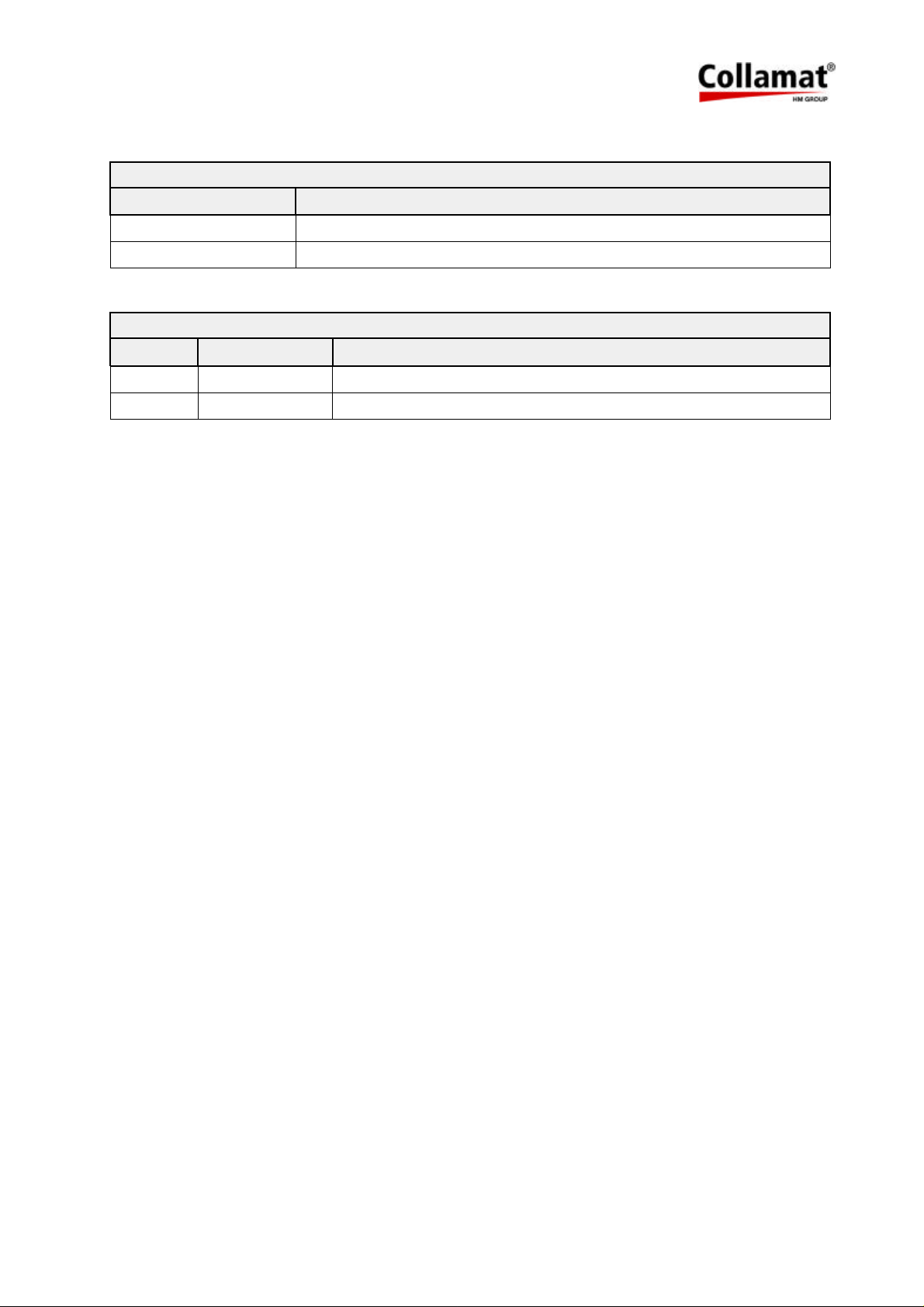
13 Version numbers
Dispenser board
Part number Version
5215.7400A Basic version from first series
5215.7400B Second revised version
Firmware
Version Date Characteristics/Modifications
1.00 06. 28. 1996 Basic version from first series
1.01 11. 28. 1996 Correct handling of the READY signal
14 Glossary and terms
14.1 Short cuts
ESD ElectroStatic Discharge
RMI Radio Magnetic Interference
GND GrouND
IR Infra Red
LED Light Emitting Diode
nc not connected
RS232 Standard serial data exchange protocol
14.2 Signals
FEED Signal indicating the labelling process
GND G
GSC Goods SCanner
IFEED Isolated FEED signal
LSC Label SCanner
nc not connected
READY READY signal from peripheral units
TCY Transparen CY, control current for the label scanner IR-diodes
rou
ND
5999.515-01E 12.06.2007 WM Page 38 / 47
Page 40

14.3 Terms
Stopping accuracy: Accuracy of the paper transportation
Unwinder: Device that carries the full paperweb rolls and unwinds it
Adapter: Part of the labeler by which the label is peeled off from the paperweb and applied
onto the products
Rewinder: Device that takes the empty paperweb from the traction unit and rewinds it
CE-Mark: Certification for the European market, means: Conformité Européenne
Collamat: Brand name for a labeler built by Collamat Stralfors AG
GSC: Goods SCanner
Flap adapter with magnet: Adapter which moves down to the product during the labelling
LSC: Label SCanner
Position: Sticking position of a label on the good
Predispensing: Predispensing of a label on the peeling plate
Motorstep: Travelling way of the label for one motorstep
Dispensing speed: The speed of the goods to which the labels are sticked
Startfrequency: Highest possible frequency for a steppermotor to start moving without loss of
steps
Traction Unit: Part of the dispenser with drive unit and electronic control
5999.515-01E 12.06.2007 WM Page 39 / 47
Page 41
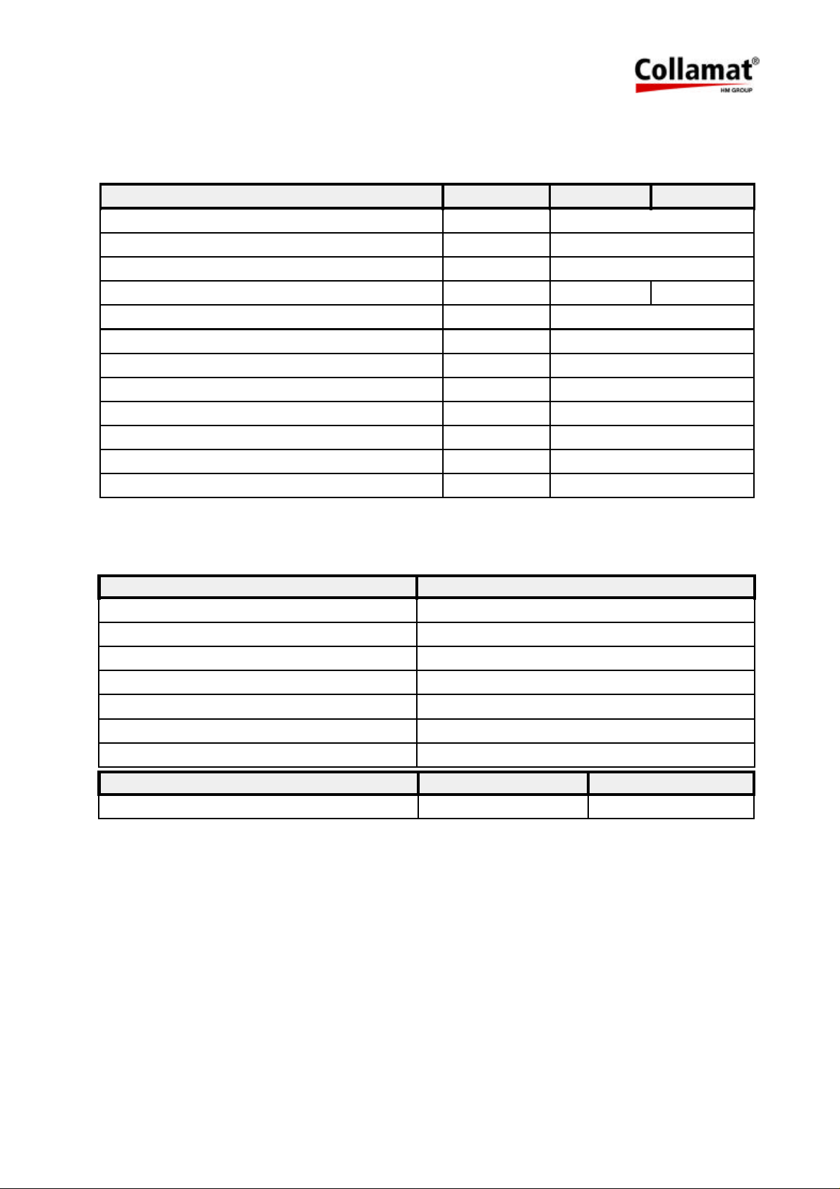
15 Technical data
Dispenser general data (standard values)
System Units
Version right/left
Dispensing speed m/min 3.0-20
Min. label width mm 10
Max. width of the paperweb mm 95 160
Min. label length mm 10
Min. label length at max. dispensing speed mm 20
Stop accuracy mm ± 1 mm @ 20 m/min
Minimal gap for optical scanner mm 2
Minimal gap for mechanical scanner mm 2
Max. diameter of paperroll mm 250/350
Max. weight of paperroll kg 10
Noise figure dBA < 70
Traction unit
System C3600
C3610 C3620
Driver 2 phase steppermotor, 200 steps
Motor voltage 40 V
Max. phase current 4.0 A
Type of protection IP40
Ambient temperature +5-40 °C
Ambient humidity 15-90%, non condensing
Noise figure max. < 70 dBA, 1 m distance
System C3610 C3620
Weight 12 kg 14 kg
5999.515-01E 12.06.2007 WM Page 40 / 47
Page 42
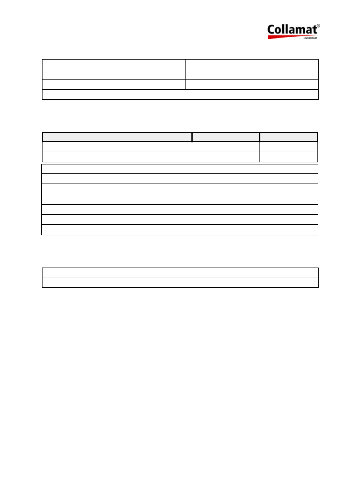
Midi-unwinder
Diameter of the roll core 42 mm
Max. outside diameter of roll 350 mm
Max. weight of roll 10 kg
Spring dancer with automatic brake
Flap adapter
System C3610 C3620
Max. width of paperweb 95 mm 160 mm
Weight 1.9 kg 2.2 kg
Version right/left
Adapter angle ±90°, with adjustable snap-in locking
Recuperating spring force adjustable
Additional press time of adapter adjustable
Max. turning angle 15°
Ambient temperature +5-40°C
Ambient humidity 15-90% non condensing
Label scanner
Optical label scanner
Mechanical label scanner
The informations in this handbook reflect the state
of the publication date.
We reserve the right to make design modifications.
5999.515-01E 12.06.2007 WM Page 41 / 47
Page 43
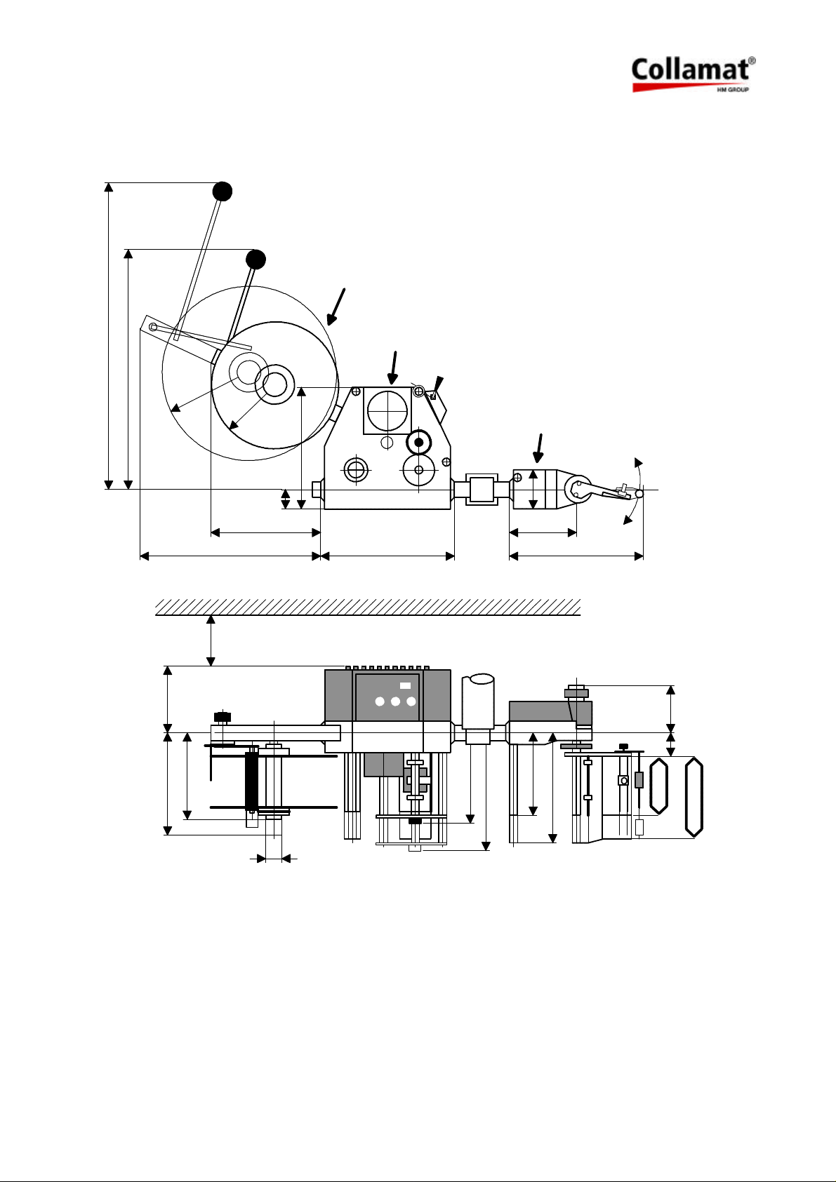
15.1 Dimensions - systemdesign
A
480
610
Ø 350
Ø 250
B
C
D
105
245
175
max. 375
min. 100
min. 225
38
Ø 40
245
266
158
223
77
140
147
212
270
95
C3610
160
C3620
A) Abwickler
B) Vorzugwerk
C) Klappenadapter
D) Für Deckelmontage
5999.515-01E 12.06.2007 WM Page 42 / 47
A) Unwinder
B) Traction unit
C) Flap adapter
D) For lid dismantling
Page 44
16 Troubleshooting
16.1 Troubleshooting Collamat 3600
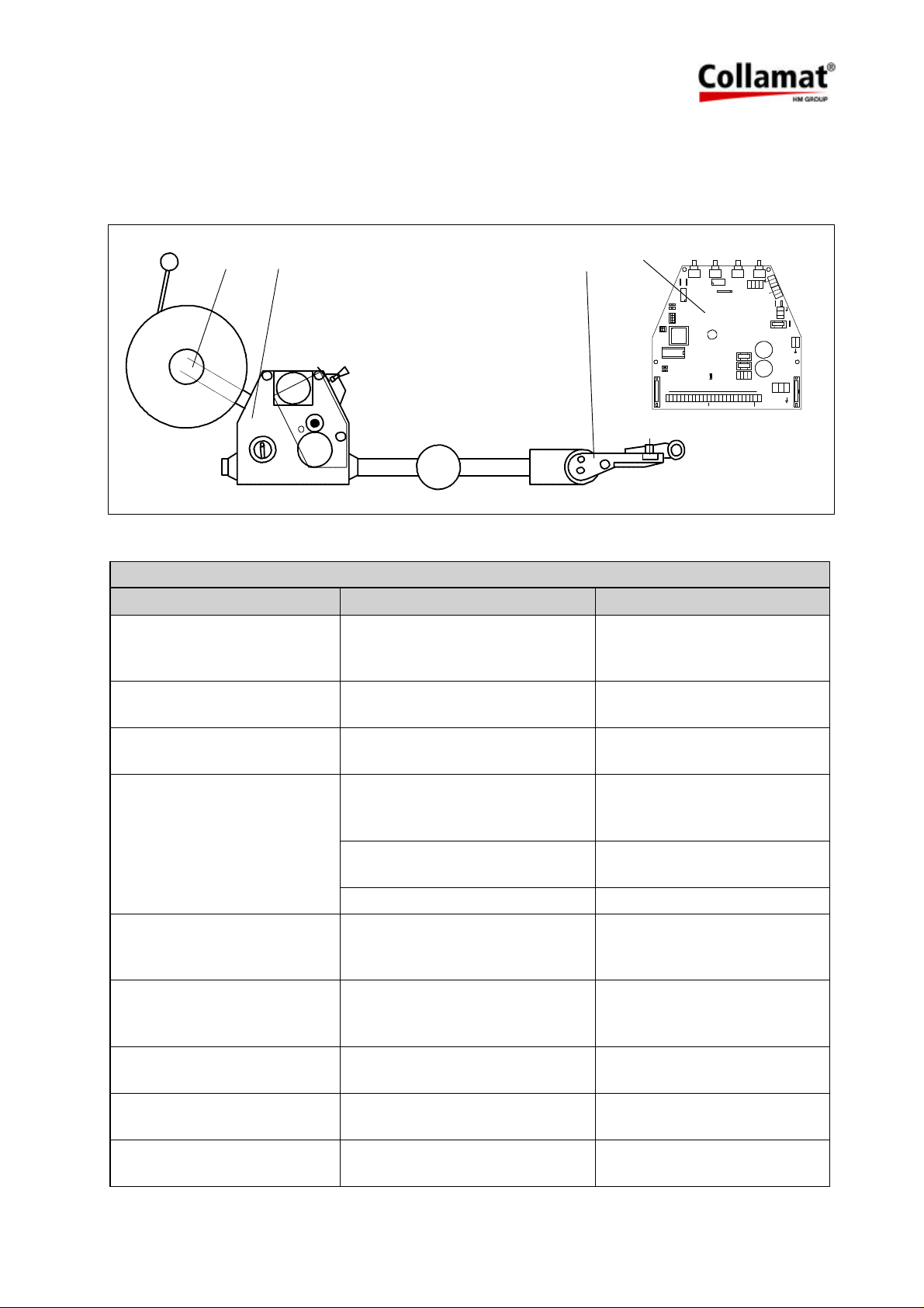
The troubleshooting will proceed along the paperpath. See following figure:
1 3 2
4
TEST
DIR
5V
12V
Unit
1. Unwinder 2. Adapter 3. Traction unit 4. Control print
1. Unwinder troubleshooting
SYMPTOM DIAGNOSIS ACTION
Labels peel off at the dancer
roll
Dancer roll diameter is too small Change the standard roll
against a roll with enlarged
diameter
Dancer arm is bent and
breaks
Dancer arm materiel is too weak
or too thin (older Collamat)
Use new dancer arms
(C3600/C6600/C8600)
SPEED POS TCY
X61
X60
X103
X104
2
1
RESET
FAULT
DEL
NS
R1
R2
X1
LSC
GND
GND
TCY
RDY
+12V
GND
+12V
+12V
FEED
GSC1
X48
7605
1
X106
X105
IFD
IFD
+12V
a3
a2
a1
1
L1
N1 X46
9 6
N
OUT
L
F1
2AT 230V
1
4AT 115V
F2
3.15AT
X36
3 3
7 7
GND
+12V
GND
GSC2
GSC3
NSTPI
NSTPO
X51
F3
1.6AT
X101X102
X39
IN
X40
X25
L N
PE
ERR
ERR
GND
+12V
Flange of the fixed disk
breaks
Material defect, wrong type of
aluminum
Replace flange against new
series flange
Unwinder blocks Disk touches the diskbrake Shift the disk on the un-
windershaft away from the
diskbrake
Shaft is blocked Lubricate the bearings on the
shaft
Diskbrake does not open Readjust the diskbrake
The torsion spring comes off
the knurled knob
Wrong kind of torsion spring Exchange the torsion spring
against an according torsion
spring
The unwinder tends to fall off
while side labeling
Paper roll too heavy Mount a separate clamp to
the module rail to stiffen the
unwinder rail
Dancer roll gets shaky Shaft screw is loose Fix the screw (use perhaps
Locktite)
Dancer bearing gets shaky Module rail is worn out by the
dancer axle
Paperweb falls off in side la-
Missing side labeling kit Mount the side labeling kit to
beling applications
Replace module rail and
dancer axle
the Collamat
5999.515-01E 12.06.2007 WM Page 43 / 47
Page 45
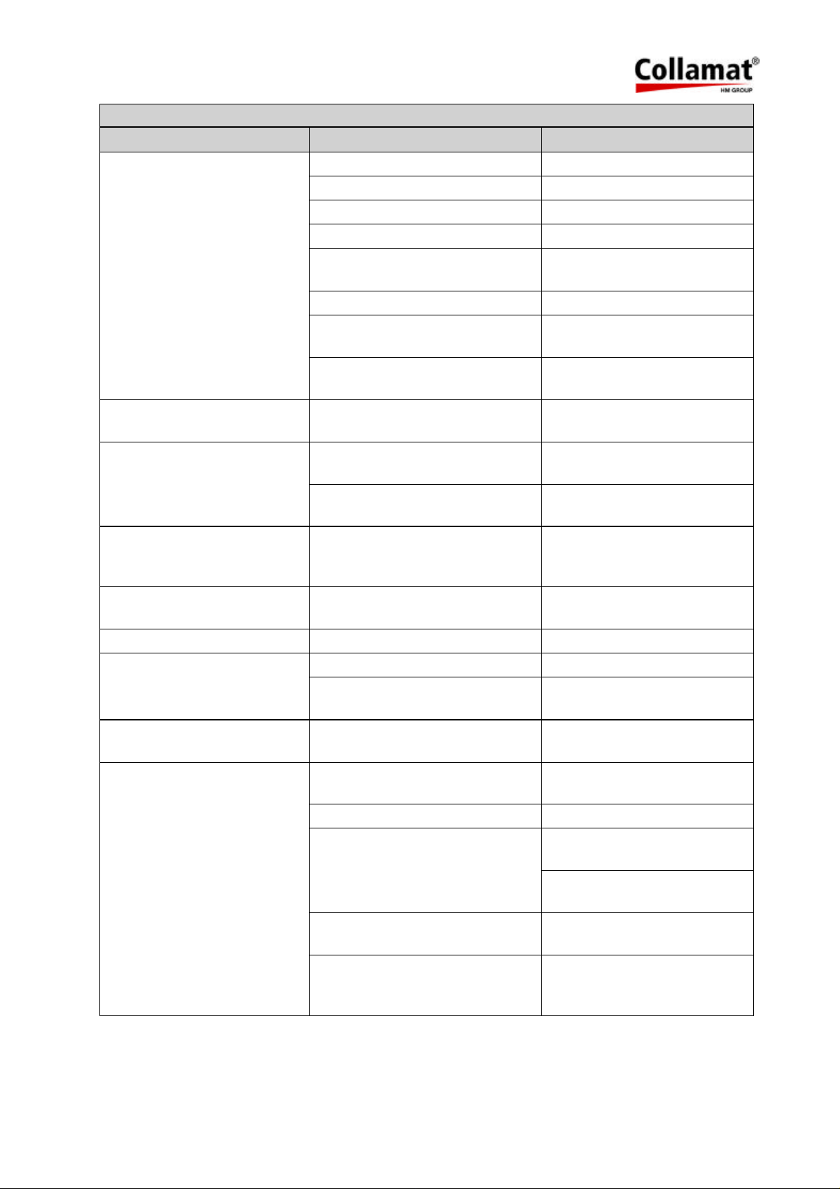
2. Adapter troubleshooting
SYMPTOM DIAGNOSIS ACTION
Labels run through Roll-up cable is broken Replace roll-up cable
Label sensor cable is broken Replace label sensor cable
IR transmitter cable is broken Replace transmitter cable
IR transmitter LED broken Replace transmitter print
Label sticks below the label
sensor
Remove the sensor and
clean it properly
IR light guide is blind Replace IR light guide
TCY-potentiometer is
misadjusted
Label scanner position not over
the label
Pressing roll is worn out Roll is pressed too hard to the
goods
Pressing roll axle hangs/is
Fixing hex nut is loose Retighten the hex nut (apply
bent down
Pressing roll axle is bent or
Readjust TCY, check
DATA-HOLD-switch
Place the scanner over the
label transport path
Lift the labeler, reduce the
adapter spring force
Locktite)
replace the axle
broken
Adapter flap gets shaky Lever fixing screw is loose Remove the flange holding
the two knurled rolls and
retighten the lever
Labels are not dispensed
Peeling bar is worn out Replace the peeling bar
straight forward
Labels form bubbles Labeling speed to fast Reduce labeling speed
Labels form wrinkles Labeling speed to slow Increase labeling speed
Adapter tilts down while
labeling
Paperweb breaks behind the
peeling bar
Labeler is misaligned to product
Realign the labeler
transport
Backing paper not threaded between the adapter roll pair
Lateral paperguides hurt the
paperweb
Tread the paperweb correctly
between the adapter roll pair
Enlarge the space between
the paperguides
Paperbrake set too hard Reduce the braking force
Peeling bar is too sharp Use peeling bar with a bigger
radius
Add Teflon tape around the
peeling bar
Peeling bar touches the goods Lift the labeler/adapter away
from the goods
Paperweb is perforated Use unperforated paperwebs
or use a peeling bar with big-
ger radius
5999.515-01E 12.06.2007 WM Page 44 / 47
Page 46
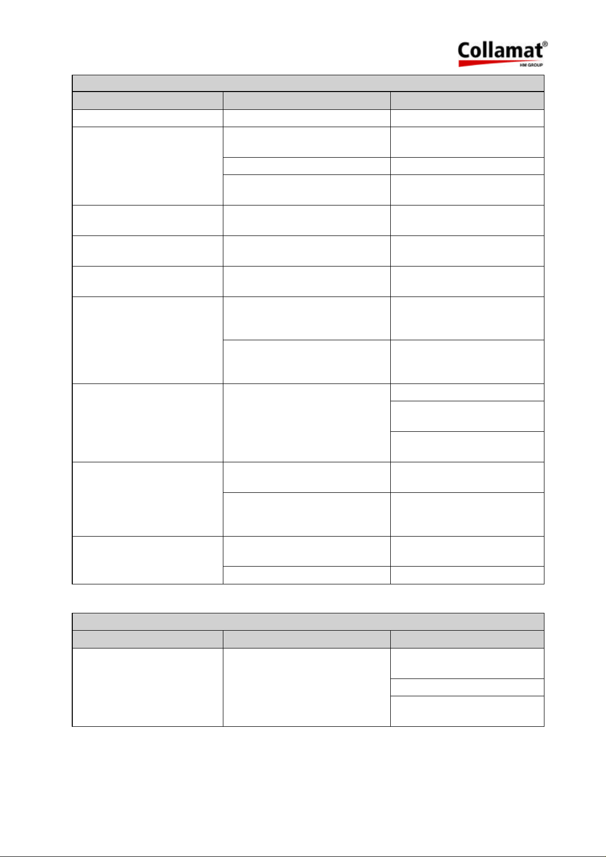
3. Traction unit troubleshooting
SYMPTOM DIAGNOSIS ACTION
Pressure roller is shaky Pressure roller shaft is broken Replace pressure roller shaft
Traction roller turns in the
wrong direction
Problems in the rewinder clutch Release the breaking force of
the rewinder
Feltdisks are worn out Replace the felt disks
Potentiometer settings have
Parallel pin inside the rewinder
shaft is blocked
DATA-HOLD-switch active Switch it off
Release the parallel pin clean
and lubricate it
no effect
Motor is very hot No fault This is normal for a stepper
motor
Motor makes high frequent
noise
Traction roller is shaky while
power on
No fault This is normal for a stepper
motor
Pin at the front flange of the tra-
tion roller is broken or worn out
Exchange pin or if necessary
exchange the complete trac-
tion roller
The toothed belt roll or the lock-
ing plate is broken
Exchange the toothed belt
roll or exchange the locking
plate and fix it tight
At higher labeling speed the
motor stalls
Too much friction of the
paperweb
Check the paperbrake
Add Teflon tape to the peel-
ing bar
At higher labeling speed the
motor stalls
Paperweb breaks behind the
paperbrake
SYMPTOM DIAGNOSIS ACTION
Motor is dead, power switch
is not illuminated
Reduce all friction of the pa-
perweb where possible
Too much friction of the
Check the unwinder dancer
paperweb
Clutching force of the rewinder
is too high
Release the breaking force of
the rewinder or
replace the felt disks
Lateral paperguides hurt the
paperweb
Enlarge the space between
the paperguides
Paperbrake set too hard Reduce the braking force
4. Control print troubleshooting
No mains connected to trafo Check for correct main
connection
Check main fuse
Check internal main switch
wiring
5999.515-01E 12.06.2007 WM Page 45 / 47
Page 47
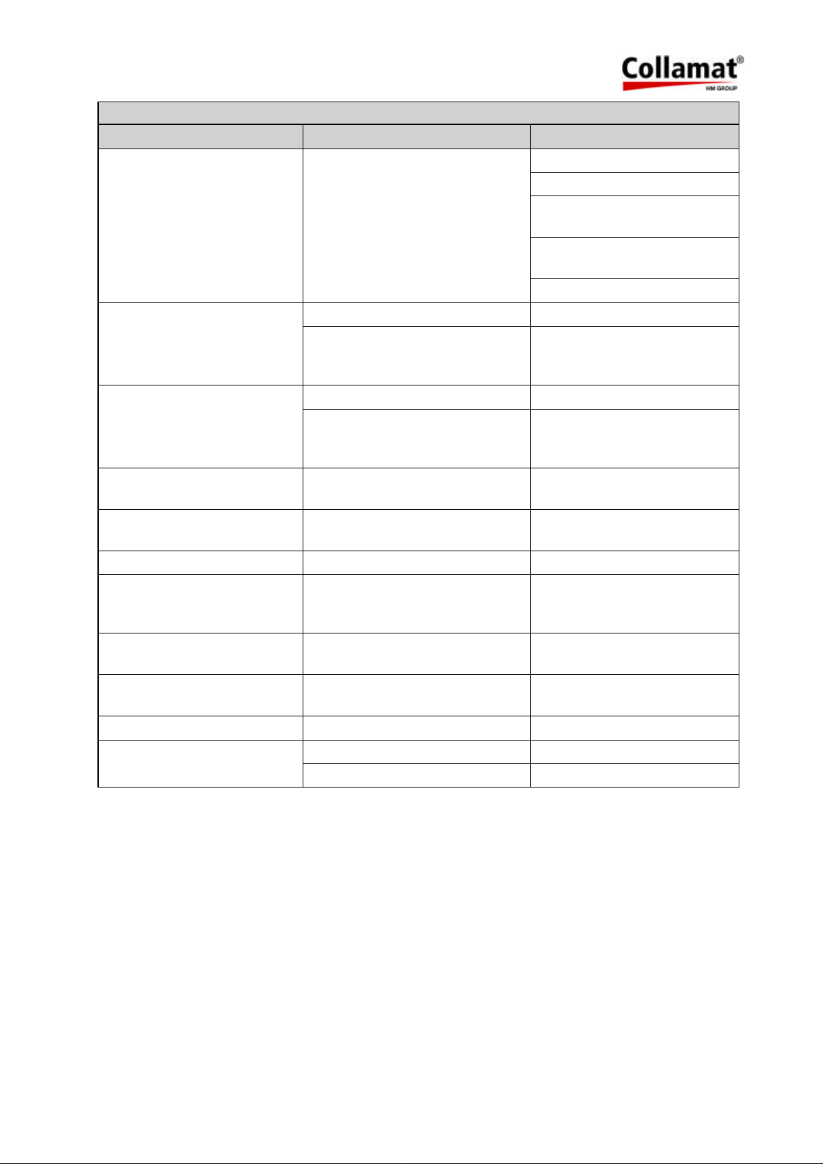
4. Control print troubleshooting
SYMPTOM DIAGNOSIS ACTION
Motor is dead, power switch
is illuminated, FAULT-LED is
on
Motor turning direction is
wrong
Motor makes noise and
shakes. It does not turn
correctly
No action after power on but
motor is under power
The potentiometers are
broken
Motordriver probably not
working
Check motordriver fuse F2
Check for undervoltage
Check for motordriver
overheat
Check on motorwires for
short connection
Check trafo wiring
Wrong DIL-switch DIR setting Change DIL-switch DIR
Wrong Motor wiring Reconnect motor wires ac-
cording to the Technical
Handbook
Faulty motor driver chip Replace the board
Missing connection of one mo-
tor wire
Connect motor wires accord-
ing to the Technical
Handbook
Probably set to Nonstop slave
Switch Nonstop mode to off
mode
Transportation damage Use the original transport box
The primary fuse often blows The mains impedance is too low Use an extended power cord
The 5V and 12V LEDs are
both off
Fuse F3 is blown, probably result of a short of the 12V in the
Check the peripheral units,
replace the fuse (1.6AT)
peripheral units
The 12V LED is off Probably result of a short of the
Check the peripheral units
12V in the peripheral units
The 5V LED is off Probably result of a short of the
Replace the board
5V in the processor part
The RESET LED is on Undervoltage of the 5V circuit Replace the board
The RESET LED periodically
flashes
Microprocessor error Replace the board
EPROM faulty Replace the EPROM
5999.515-01E 12.06.2007 WM Page 46 / 47
Page 48
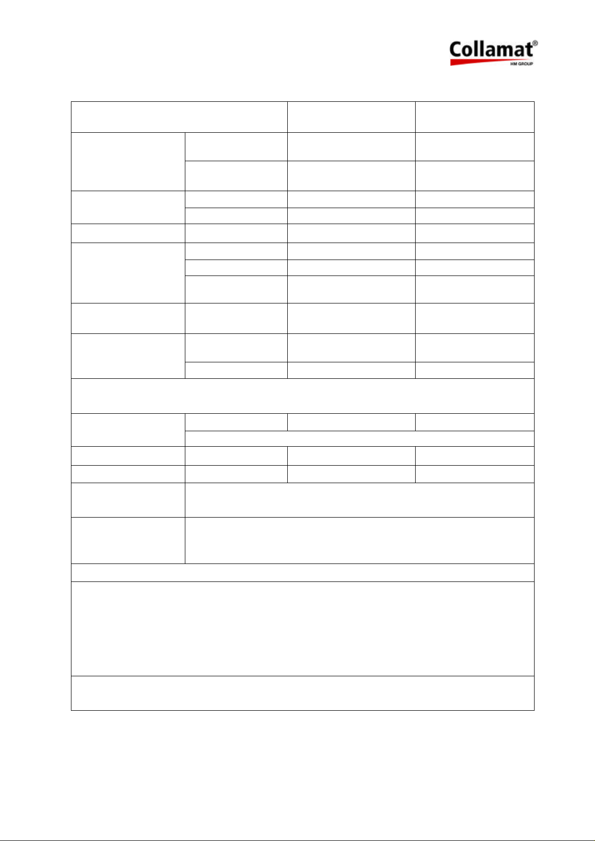
16.2 Trouble shooting checklist
Machine-Type:
Environment
Labels
Paperweb
Goods
Labeler
Settings
Special:
Ser. No. Dispenser board: Ser. No. Labeler:
Mains voltage: Frequency Hz: Temperature °C:
Humidity %:
Width: Length: Gap:
Thickness: Transparency: Material:
Width: Thickness: Transparency:
Kind: Material: Shape:
Length: Width: Height:
Speed m/min Length in sense
Speed m/min: Pieces / min: Measuring:
Predispensing: Position mm: Suppression:
TCY value: Label length: Suppression:
Interference level (Burst): Interference level ESD
(Static):
Distance between
of transport:
goods:
Machineenvironment
Peripheral units
Screening
ESD-Phenomena
Description of the
Conveyor: Feeder: Taker:
Other machines around:
1 2 3
Mains cables: Sensor cables:
Description:
Accumulation:
malfunctions:
Date / ev. date and time of the last disturbances:
Comments:
Disturbance registered by Name:
Date:
Please make a copy of this list before using it.
5999.515-01E 12.06.2007 WM Page 47 / 47
 Loading...