

Page 1
WARRANTY
COLE-PARMER INSTRUMENT CO. , for itself does hereby offer a warranty for products from the date of receipt by the user, under normal
and proper usage, against defects in workmanship and materials for 12
months, and will repair or replace any defective part ( s) without charge
when same is shipped Prepaid to COLE_PARMER INSTRUMENTS
from which the product was originally
purchased.
Should the nature of any defect require that the product , or any constituent portion thereof , be returned to Cole-Parmer Instrument Co.,
Vernon Hill, Illinois, prepaid for service, a condition precedent to any
return shall be the procurement of authorization from Cole-Parmer Instrument Co. assigning a Return Goods Number to the product or part
requiring service.
Parts and accessories manufactured by others are warranted only to
the extent of the regular warranty of the manufacturer or supplier of
such materials and only insofar as Cole-Parmer Instrument Co. is able
to transfer the benefits of warranty coverage, if any , to the user. Any
adequately warranted defective part or accessory manufactured or supplied by others may be exchanged through Cole-Parmer Instrument Co.
for a replacement part is shipped prepaid and received at Cole-Parmer
Instrument Co. within 30 days from the date any replacement part is
obtained by the user.
This warranty supersedes and is given in lieu of all implied warranties,
and is void if the user causes damages from improper usage of product
under normal operating conditions.
12 MONTHS LIMITED WARRANTY ON ALL PARTS AND LABOR IS
GIVEN BY COLE-PARMER INSTRUMENT COMPANY
CATALOG NUMBER 28680-30
SERIAL NUMBER _________
DATE OF PURCHASE _______________
page 8
Operation Manual
Cole-Parmer Model Z1800
Catalog No. 28680-30
18 position ZipVap
Cole-Parmer Instrument Company
625 East Bunker Court, MS 18
Vernon Hills, Illinois 60061-1844, U.S.A
Phone: 847-549-7600 Fax: 847-549-7676
( 800) 323-4340
Page 2

INTRODUCTION
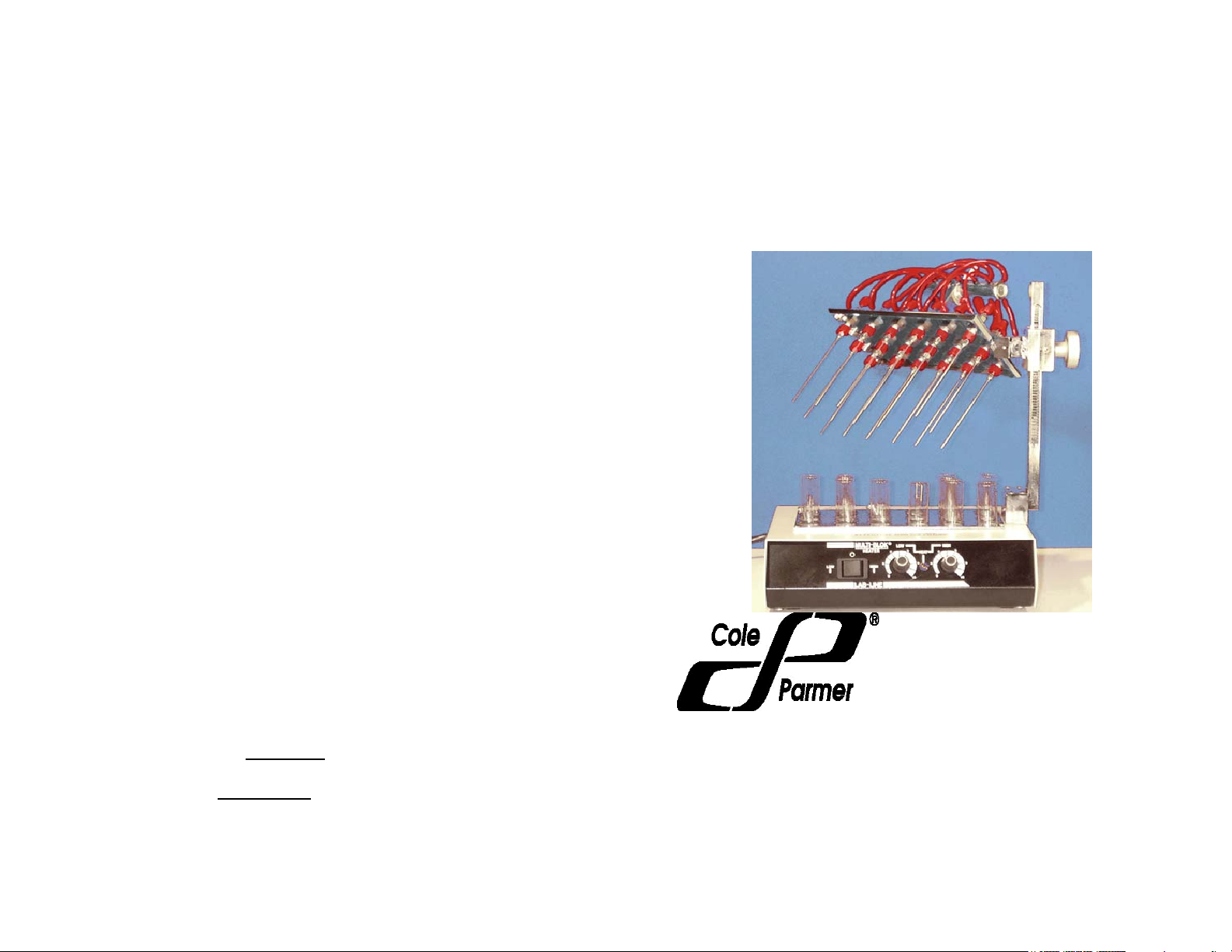
Cole-Parmer Instruments Z1800 Cat# 28680-30 Evaporator and Con-
centrator is designed to provide rapid evaporation of solvents or water
for 18 samples, test tubes or containers. It is supplied with a triple
block heater. It includes 18 individual needle valves for controlling the
flow to each positions containers. It is designed to be easily accessible
with the geared height adjustment and a manifold swing away platform.
1 to 18 samples can be utilized for evaporation at any time.
Materials of Construction
Cole-Parmer Model Z1800 evaporator is fabricated with aluminum,
brass, and plastic. All brass pats are nickel plated for corrosion resistance.
Features
► compact size to take minimal space
► rectangular manifold plate that pivots 90˚ forward and backward, and
it will rotate 360° horizontally for easy access to needles and valves.
► a rack to be able to insert different tubes and easily align the needles
for evaporation
► accomadates tubes or containers from 8 mm to 25 mm diameter with
volumes from 1 ml to 50 ml.
► 18 individual fine needle control valves
► 18 stainless steel needles 4 inch x 16-gauge
Contents
Page 1- Title Page
Page 2– Introduction and Table of Contents
Page 3- System Specifications
Page 4- User Instructions
Page 5- Drawing
Page 6- Parts List
Page 7- Maintenance
Page 8- Warranty
Page 2
Maintenance
BE ADVISED:
NOTE: MAKE NO ATTEMPT TO SERVICE OR REPAIR A COLEPARMER PRODUCT UNDER WARRANTY BEFORE CONSULTING
COLE-PARMER.
AFTER THE WARRANTY PERIOD, SUCH CONSULTATION IS STILL
AD-VISED, ESPECIALLY WHEN THE REPAIR MAY BE TECHNICALLY SOPHISTICATED OR DIFFICULT.
IF ASSISTANCE IS NEEDED, PLEASE CALL COLE-PARMER
AT 847- 549-7600OR FAX US AT 847-.549-7676
NO MERCHANDISE, HOWEVER, SHOULD BE RETURNED DIRECTLY TO COLE-PARMER WITHOUT PRIOR APPROVAL FROM
COLE_PARMER
CAUTION: IF UNIT IS SUPPLIED WITH HEATER DISCONNECT
PLUG FROM ELECTRICAL OUTLET BEFORE ATTEMPTING ANY
MAINTENANCE OR REPAIR.
PARTS REPLACEMENT:
Unplug heater from outlet. Remove it from evaporator. Identify and
replace defective parts by referring to drawing on page 6 and parts
list page 7.
If replacement parts are needed please contact COLE-PARMER.
GENERAL MAINTENANCE:
Unplug heater after use. Clean the inside. This will insure proper
operation for an extended period of time.
Page 7
Page 3

Parts List
Part Number
1. 10-- 00011—00 Manifold Plate
2. 12—00012—00 Top Clamping device for manifold
3. 12 – 00013—00 Bottom clamping device for manifold
4. 10 – 00014—00 Manifold cylinder
5. 10 – 00015—00
6. 18 – 00016—00 Support Post
7. 12 – 00017—00 Inner Part for gear assembly
8. 14 – 00018—00 Height positioning knob
9. 18 – 00019—00 Gear holding rack
10. 12 – 00110—00 Inner Part for gear assembly
11. 14 – 00111—00 (4) ½” 10-32 LPSC
12. 12 – 00112—00 Inner Part for gear assembly
13. 12 – 00113—00 Inner Part for gear assembly
14. 12—00114—00 Inner Part for gear assembly
15. 12 – 00115—00 Inner Part for gear assembly
16. 14 – 00116—00 Inside support bar
17. 24 – 00117—00 4” SS luer Needle
18. 28 – 00118—00 Male Luers 10-32
19. 10 – 00119—00 Needle valve/ 10-32 * .062 Black fitting
20. 26 – 00120—00 Red handle
21. 10 – 00121—00 (18 ) Polyurethane Tube 1/8 x 1/16
22. 10 – 00122—00 ½” 10-32 Low profile socket screws
23. 10 – 00123—00 (18 pcs.)10-32 Black Nylon fitting for
1/16” tube
24. 18 – 00124—00 (3) ¼” 10-32 Low profile socket screw
25. 18 – 00125—00 Base post holder
26. 30 – 00126—00 Lab-Line triple block heater
27. 30 – 00127—00 Test tube rack
28. 30—00128—00 Zirconia beads for heater (500cc)
NEED A PEPLACEMENT PART? CALL COLE-PARMER
Phone: 847-549-7600 Fax: 847-549-7676
Cole-Parmer Instruments reserves the right to make changes to
specifications without prior notice.
page 6
Description
¼” tube inlet
System Specifications
Z-1800 System Specifications
Number of samples 18
Bench space 16.5 x 11 x 15 in.
(w x d x h) 18 x 33 x 46 cm
Test tube size range 8 to 25 mm
Type of Gas Nitrogen or Air
Gas Flow 0 to 10 Liters/min.
The instrument consists of a base and stand assembly, a sample holder, and a gas
distribution system. Test tubes (or other containers) can be held in position by the
Zirconia beads. Each position is numbered. Gas passes through a constant pressure
manifold assuring an equal access to each valve to the amount of gas needed. Gas is
supplied by a flexible 1/4” od. x 1/8” id silicone tube to the manifold, inert red
polyurethane tubing supplies each needle valve with gas from the manifold. The depth
can be lowered to any desired height. The height depends on the container, bath
temperature , the solvent to be evaporated, and flow rate of the evaporating gas.
Evaporation rate depends on both temperature and flow rate of the gas. Flow can be
adjusted with the individual needle valves. Gas pressures up to a maximum of 40 psig
can be utilized. Most applications require only 10 to 25 psig.
All materials used are laboratory quality and can be used with all standards organic
solvents and water including mild acid and bases.
Typical Evaporation Rates
boiling heater time to flow
Solvent point temp dryness rate
Name
Hexane 69°C 22°C 10 min 100 cc/min
Methylene
Chloride 40°C 37°C 12 min 300 cc/
Methanol 65°C 63°C 20 min 300 cc/min
page 3
min
Page 4

User Instructions
1. Place unit in required area to be used with an exhaust apparatus
such as a hood.
Evaporation of water does not need an exhaust.
2. Attach the 1/4 inch inlet of the round distribution manifold located on
top of the unit to Nitrogen or air source
Refer to drawing diagram page 5 part no. 5.
3. Raise needle holder plate to desired height by using knob
part no. 8 .
Refer to drawing diagram page 5, part no. 8.
4. A light push or twist on manifold plate will unlock the plate and it will
rotate for easy access to all tubes.
Refer to page 5, no. 1
5. Twist lightly on the left side of the manifold plate for up to 90° de-
grees of pivot forward, and/or backwards for easy access to needles
and valves.
Refer page 5, no. 1
6. Insert test tubes in one or more of the 18 position test tube holder
provided. Sizes 8 mm diameter to 25 mm diameter can be used.
7. Lower the needle holder plate by using gear knob part no. 8 in the
figure on page 5 to desired height.
Refer to figure page 5, no. 8.
8. Adjust test tubes so that the needle will be centered in the tube and
lower needles to desired height.
9. Adjust gas flow by using the individual needle valves. We suggest
you set gas flows by first fully opening the valves (counter clock
wise), then setting desired flows. It is suggested to start flow
adjustment with the fine needle valve fully open (counterclockwise)
then reduce flow to desired amount.
10. Set heater to desired temperature.
11. Caution: Do not over tighten needle valves. Over tightening can
causebreakage. To shut off a port use the supplied plugs, not the
valve.
If you have any questions please contact Cole-Parmer on the use
of this product. Phone: 847-549-7600 Fax: 847-549-7676
page 4
Model Z1800
No. of samples 18
Model No. Z1800
Bench space 16.5 x11 x 15 in
( w x d x h ) ( 42 x 28 x 38 cm )
page 5
 Loading...