

Page 1
User Manual
01-26-18 REV03
Cole-Parmer Symmetry Balances
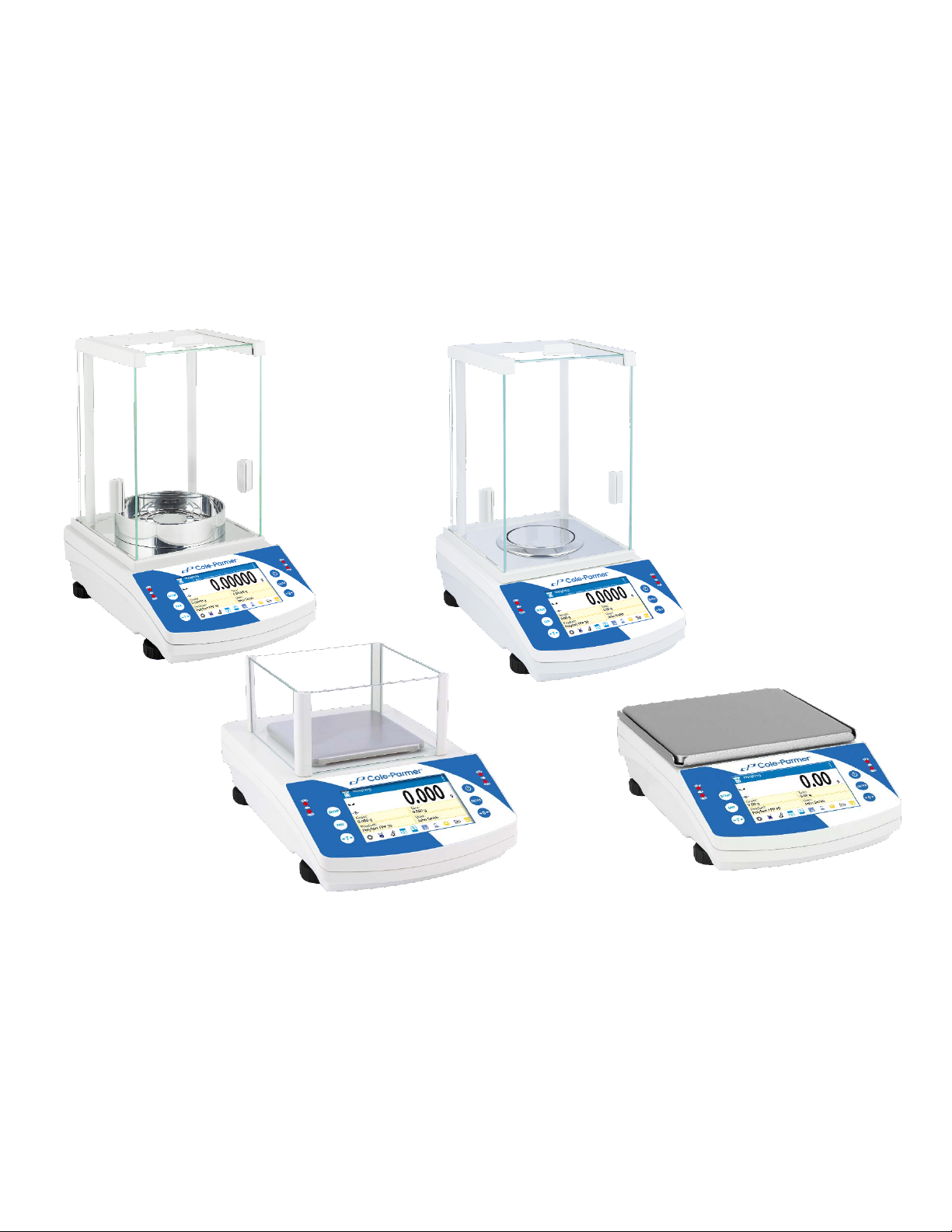
Analytical Balances: TA.C and TA Series
Precision Toploading Balances: TT.C and TT Series
1
Page 2

2
Page 3

Contents
1. GENERAL INFORMATION ..................................................................................................................................... 7
1.1 INTENDED USE ................................................................................................................................................................... 7
1.2 PRECAUTIONS ................................................................................................................................................................... 7
1.3 SUPERVISION OVER METROLOGICAL PARAMETERS .......................................................................................................... 7
1.4 WARRANTY CONDITIONS ................................................................................................................................................... 7
2. UNPACKING AND INSTALLATION ....................................................................................................................... 8
2.1 PLACE OF USE AND ASSEMBLING ....................................................................................................................................... 8
2.2 STANDARD DELIVERY COMPONENTS LIST.......................................................................................................................... 8
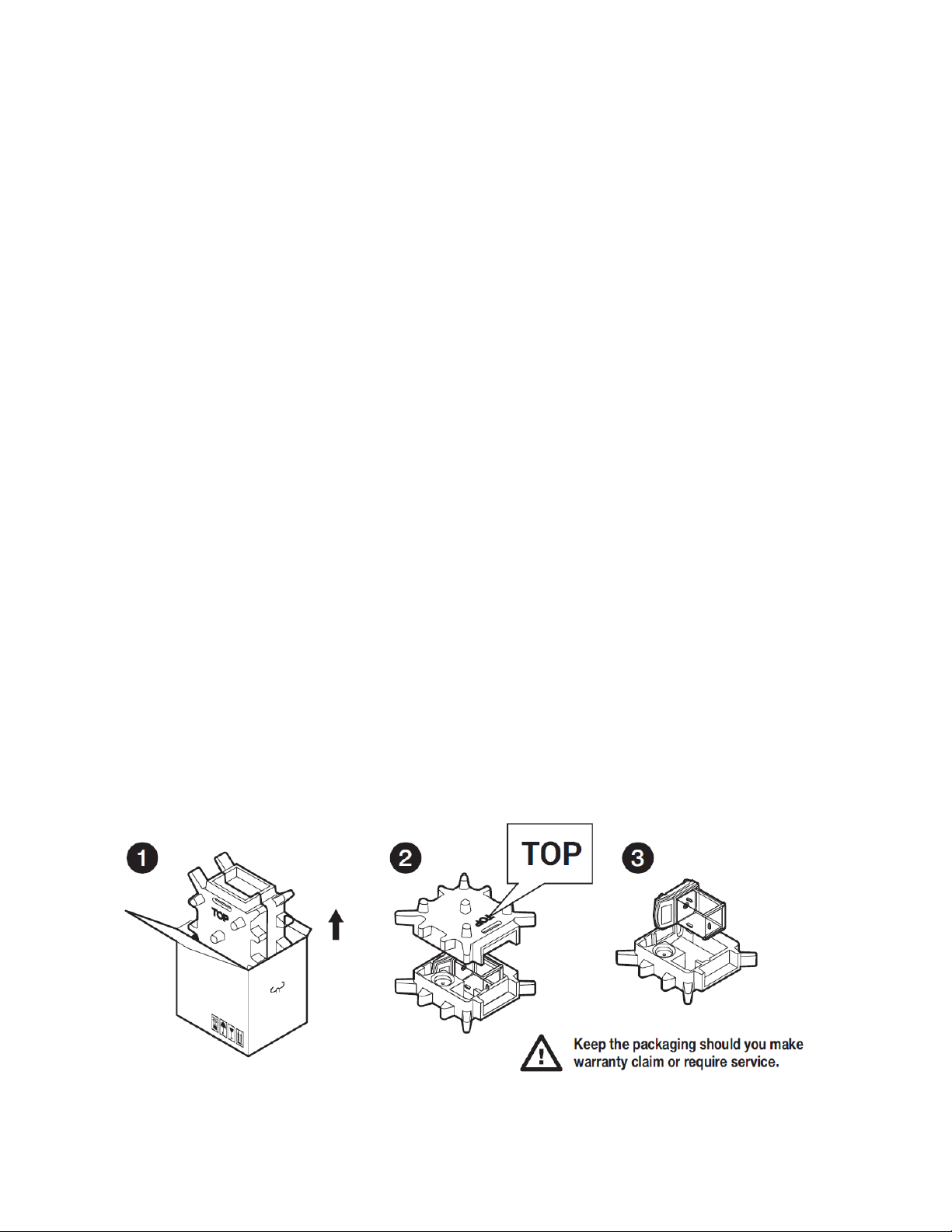
2.3 UNPACKING ....................................................................................................................................................................... 8
2.4 BALANCE ASSEMBLY .......................................................................................................................................................... 9
2.5 BALANCE LEVELING .......................................................................................................................................................... 14
2.6 POWERING THE DEVICE ................................................................................................................................................... 15
3. BALANCE CONTROL ........................................................................................................................................... 15
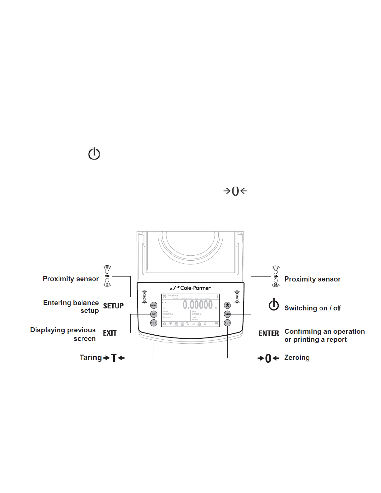
3.1 BALANCE KEYBOARD ........................................................................................................................................................ 15
3.2 BALANCE HOME SCREEN.................................................................................................................................................. 16
3.3 ENTERING BALANCE MENU ............................................................................................................................................. 16
3.4 SCREEN SCROLLING .......................................................................................................................................................... 17
3.5 SOFT KEYS LIST ................................................................................................................................................................. 17
4. WEIGHING MODE .................................................................................................................................................. 18
4.1 GOOD WEIGHING PRACTICE ............................................................................................................................................ 18
4.2 UNITS ............................................................................................................................................................................... 19
4.3 USER-DEFINED UNIT ........................................................................................................................................................ 20
4.4 BALANCE ZEROING ........................................................................................................................................................... 20
4.5 BALANCE TARING ............................................................................................................................................................. 21
4.5.1 MANUAL TARE DETERMINATION ............................................................................................................................. 21
4.5.2 DELETING TARE ........................................................................................................................................................ 21
4.5.3 TARE DATABASE ....................................................................................................................................................... 22
4.6 WEIGH MODE SETTINGS .................................................................................................................................................. 22
4.6.1 FILTER LEVEL SETTINGS ............................................................................................................................................ 23
4.6.2 VALUE RELEASE ........................................................................................................................................................ 23
4.6.3 AUTOZERO FUNCTION.............................................................................................................................................. 23
4.6.4 LAST DIGIT DISPLAY .................................................................................................................................................. 24
4.6.5 BALANCE AMBIENT CONDITIONS ............................................................................................................................. 24
5. ADJUSTMENT (TA.C AND TT.C SERIES) .......................................................................................................... 24
5.1 INTERNAL ADJUSTMENT .................................................................................................................................................. 24
5.1.1 AUTOMATIC ADJUSTEMENT .................................................................................................................................... 24
5.1.2 MANUAL INTERNAL ADJUSTMENT ........................................................................................................................... 25
5.2 EXTERNAL ADJUSTMENT .................................................................................................................................................. 25
5.3 USER ADJUSTEMENT ........................................................................................................................................................ 25
5.4 ADJUSTMENT TEST .......................................................................................................................................................... 26
6. ADJUSTMENT (TA AND TT SERIES) ................................................................................................................. 26
6.1 EXTERNAL ADJUSTMENT .................................................................................................................................................. 26
3
Page 4

6.2 USER ADJUSTEMENT ........................................................................................................................................................ 27
7. WORKING MODES- GENERAL INFORMATION ............................................................................................... 27
7.1 RUNNING WORKING MODE ............................................................................................................................................. 28
7.2 QUICK ACCESS KEYS FOR EACH WORKING MODE ............................................................................................................ 28
8. PARTS COUNTING ................................................................................................................................................ 30
8.1 SUPPLEMENTARY SETTINGS FOR PARTS COUNTING MODE ............................................................................................ 31
8.2 PARTS COUNTING – QUICK ACCESS KEYS ......................................................................................................................... 32
8.3 PARTS COUNTING PROCEDURE ....................................................................................................................................... 32
8.4 SETTING REFERENCE BY ENTERING DETERMINED PART MASS ........................................................................................ 33
8.5 SETTING REFERENCE MASS BY DETERMINING PART MASS .............................................................................................. 33
8.6 ACQUIRING PART MASS FROM A DATABASE ................................................................................................................... 35
9. CHECKWEIGHING ................................................................................................................................................. 36
9.1 SUPPLEMENTARY SETTINGS FOR CHECKWEIGHING MODE ............................................................................................. 36
9.2 CHECKWEIGHING – QUICK ACCESS KEYS .......................................................................................................................... 36
9.3 MAKING USE OF CHECKWEIGHING THRESHOLDS ............................................................................................................ 36
10. DOSING ............................................................................................................................................................... 38
10.1. SUPPLEMENTARY SETTINGS FOR DOSING MODE ......................................................................................................... 38
10.2 DOSING – QUICK ACCESS KEYS ....................................................................................................................................... 38
10.3 MAKING USE OF PRODUCTS DATABASE FOR DOSING OPERATION ................................................................................ 39
11. PERCENT WEIGHING ....................................................................................................................................... 40
11.1. SUPPLEMENTARY SETTINGS FOR PERCENT WEIGHING ................................................................................................ 40
11.2 PERCENT WEIGHING – QUICK ACCESS KEYS ................................................................................................................... 40
11.3 COMPARISON OF SAMPLE OF REFERENCE MASS ........................................................................................................... 41
12. DENSITY OF SOLIDS ........................................................................................................................................ 43
12.1 SUPPLEMENTARY SETTINGS FOR SOLIDS DENSITY MODE.............................................................................................. 44
12.2. SOLIDS DENSITY – QUICK ACCESS KEYS ......................................................................................................................... 44
12.3 SOLIDS DENSITY DETERMINATION ................................................................................................................................. 44
13. DENSITY OF LIQUIDS ...................................................................................................................................... 47
13.1 SUPPLEMENTARY SETTINGS FOR LIQUIDS DENSITY MODE ............................................................................................ 47
13.2 LIQUIDS DENSITY – QUICK ACCESS KEYS ........................................................................................................................ 48
13.3 LIQUIDS DENSITY DETERMINATION ............................................................................................................................... 48
14. ANIMAL WEIGHING .......................................................................................................................................... 50
14.1 SUPPLEMENTARY SETTINGS FOR ANIMAL WEIGHING MODE ........................................................................................ 50
14.2. ANIMAL WEIGHING – QUICK ACCESS KEYS ................................................................................................................... 51
14.3 ANIMAL WEIGHING PROCEDURE ................................................................................................................................... 51
15. STATISTICS ....................................................................................................................................................... 52
15.1. SUPPLEMENTARY SETTINGS FOR STATISTICS MODE ..................................................................................................... 53
15.2. STATISTICS – QUICK ACCESS KEYS ................................................................................................................................. 53
15.3 PARAMETERS FOR SERIES OF MEASUREMENT .............................................................................................................. 53
16. PEAK HOLD ....................................................................................................................................................... 54
4
Page 5

16.1 SUPLEMENTARY SETTINGS FOR PEAK HOLD MODE ....................................................................................................... 54
16.2. PEAK HOLD – QUICK ACCESS KEYS ................................................................................................................................. 54
16.3 MEANS OF OPERATION .................................................................................................................................................. 55
17. FORMULATIONS ............................................................................................................................................... 55
17.1 SUPPLEMENTARY SETTINGS FOR FORMULATIONS MODE ............................................................................................. 56
17.2. FORMULATIONS – QUICK ACCESS KEYS ........................................................................................................................ 56
17.3 ADDING FORMULATION TO FORMULATIONS DATABASE .............................................................................................. 57
17.4 USING FORMULATIONS FOR WEIGHING ........................................................................................................................ 59
17.5 PERFORMED FORMULATIONS REPORT .......................................................................................................................... 64
18. DATABASES ...................................................................................................................................................... 65
18.1 DATABASE CONNECTED OPERATIONS ........................................................................................................................... 65
18.2 PRODUCTS ..................................................................................................................................................................... 66
18.3 OPERATORS ................................................................................................................................................................... 67
18.4 PACKAGING .................................................................................................................................................................... 68
18.5 CUSTOMERS ................................................................................................................................................................... 68
18.6 FORMULATIONS............................................................................................................................................................. 68
18.7 FORMULATIONS REPORTS ............................................................................................................................................. 69
18.8 AMBIENT CONDITIONS .................................................................................................................................................. 69
18.9 WEIGHING RECORDS ..................................................................................................................................................... 70
18.10 ALIBI ............................................................................................................................................................................. 70
19. COMMUNICATION............................................................................................................................................. 71
19.1 RS 232 PORTS SETTING................................................................................................................................................... 71
19.2 ETHERNET PORT SETTINGS ............................................................................................................................................ 72
19.3 WI-FI PORT SETTINGS (TA.C AND TT.C SERIES)................................................................................................................. 72
19.4 USB PORT ....................................................................................................................................................................... 75
20. PERIPHERAL DEVICES ................................................................................................................................... 79
20.1 COMPUTER .................................................................................................................................................................... 80
20.2 PRINTER ......................................................................................................................................................................... 81
20.3 SAVE MEASURMENT DATA ONTO USB FLASHDRIVE ...................................................................................................... 81
21. USER ................................................................................................................................................................... 82
22. PRINT MODE ...................................................................................................................................................... 83
22.1 ADJUSTMENT PRINTOUT REPORT .................................................................................................................................. 84
22.2 ADJUSTMENT PRINTOUT REPORT .................................................................................................................................. 86
23. PROXIMITY SENSORS ..................................................................................................................................... 88
24. ADVANCED FEATURES ................................................................................................................................... 90
24.1 BUTTON, LABELS AND TEXT FIELDS CONFIGURATION ................................................................................................... 90
24.2 LABELS ........................................................................................................................................................................... 93
24.3 TEXT FIELDS .................................................................................................................................................................... 95
24.4 BAR GRAPHS .................................................................................................................................................................. 98
24.5 QUICK ACCESS KEYS CUSTOMIZATION ......................................................................................................................... 100
24.6 WEIGHING UNIT ACCESSIBILITY ................................................................................................................................... 101
24.7 START UNIT SELECTION ................................................................................................................................................ 102
5
Page 6

24.8 BALANCE SETTINGS ...................................................................................................................................................... 102
25. MAITENANCE .................................................................................................................................................. 106
26. ACCESSORIES ................................................................................................................................................ 109
26.1 DENSITY DETERMINATION KIT ..................................................................................................................................... 109
27. APPENDIX ........................................................................................................................................................ 113
27.1 TA.C AND TT.C SERIES .................................................................................................................................................. 113
27.2 TA AND TT SERIES ......................................................................................................................................................... 113
27.2 DIMENSIONS ................................................................................................................................................................ 114
27.4 CONNECTORS .............................................................................................................................................................. 115
27.6 ERROR MESSAGES ........................................................................................................................................................ 116
27.7 WARRANTY CARD ........................................................................................................................................................ 116
6
Page 7

1. GENERAL INFORMATION
1.1 INTENDED USE
The balances are designed to provide accurate measurement of weighed loads, performed under
laboratory conditions.
1.2 PRECAUTIONS
• Prior to first use, it is highly recommended to carefully read this User Manual, and operate
the balance as intended.
• Do not operate the touch panel using sharp-edged tools (knife, screwdriver, etc.).
• While loading the balance make sure that load is placed in the very center of the weighing
pan.
• Make sure the load does not exceed instrument’s measuring range (maximum capacity).
• Do not leave heavy loads on the weighing pan for a long period of time.
• In case of failure, immediately unplug the instrument.
• Balances to be decommissioned, should be decommissioned in accordance with valid legal
regulations.
• Do not use the balance is areas endangered with explosion. The balance is not designed to
operate in EX zones.
1.3 SUPERVISION OVER METROLOGICAL PARAMETERS
Metrological parameters of a balance need to be checked by an authorized user. Inspection
frequency is qualified by the ambient conditions in which a balance is used, processes carried out
and adopted quality management system.
1.4 WARRANTY CONDITIONS
A. Cole Parmer will exchange, replace or repair the existing balance for any damage that
appears to be faulty by production or by construction within the 5-year warranty period.
B. Warranty is voided if:
• mechanical defects caused by inappropriate use:
• defects of thermal and chemical origin,
• defects caused by lightning, overvoltage in the power network
• defects caused by water damage
• or other random event
• overloading the mechanical measuring system
• installing another version of the operating system
• utilizing the balance contrary to its intended use
• repairs carried out by non-authorized service centers
• removing or destroying protective stickers which secure the balance’s housing against
unauthorized access
C. Warranty card must be filled out for warranty to be valid.
7
Page 8
2. UNPACKING AND INSTALLATION
2.1 PLACE OF USE AND ASSEMBLING
• The balance should be stored and used in locations free of vibrations and shakes, free of air
movement and dust.
• Ambient air temperature should not exceed the range of: +10 °C ÷ +40 °C.
• Ambient relative humidity should not exceed 80%.
• During balance operation, ambient temperature in the weighing room should not change
rapidly.
• The balance should be located on a stable wall console desk or a stable working table which
is not affected by vibrations and distant from heat sources.
• Take special precaution when weighing magnetic objects, as part of the balance is a strong
magnet. Should such loads be weighed, use under-pan weighing option, which removes the
weighed load from area influenced by the balance’s magnet. The hook for under-pan
weighing is installed in balance’s base.
• Keep all package element should your device be transported in the future. Remember that
only original packaging can be used for shipping purposes. Prior to packing, uncouple any
cables, remove any separable components (weighing pan, shields, inserts). Pack the device
components into an original packaging. The original packaging protects the equipment
against potential damage during transportation.
2.2 STANDARD DELIVERY COMPONENTS LIST
• Balance and components shown in Section 2.4 depending on balance model
• Warranty Ca rd
• USB
o User Manual
o Balance USB Driver
o RLAB Software
o RLAB Software Manual
2.3 UNPACKING
To unpack the system, follow the diagram below-
8
Page 9
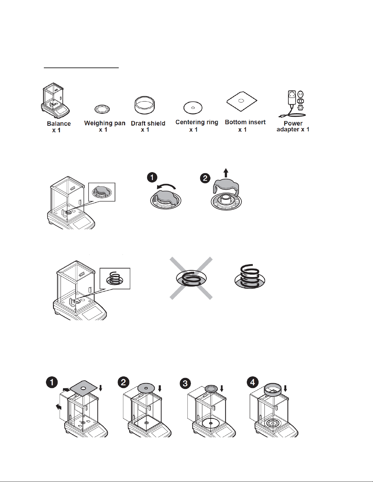
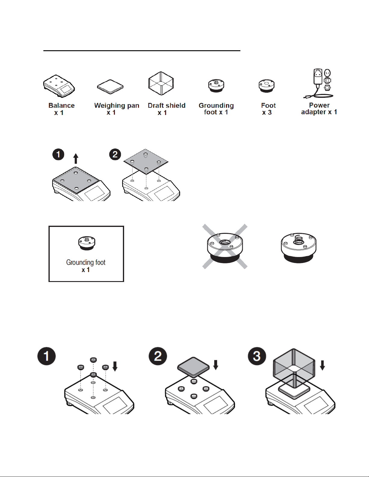
2.4 BALANCE ASSEMBLY
Model: TA-225.C, TA-64
Components:
Installation:
1) Remove the transport lock– gently press the transport lock and turn it accordingly to
<OPEN>, keep the transport lock should your balance be transported in the future.
2) Check grounding spring to insure it is in the appropriate location. Make sure that the grounding
spring juts slightly out of the hole.
3) Install components following diagram below:
i. Bottom insert
ii. Centering ring [embossment side up]
iii. Weighing pan
iv. Draft shield
9
Page 10
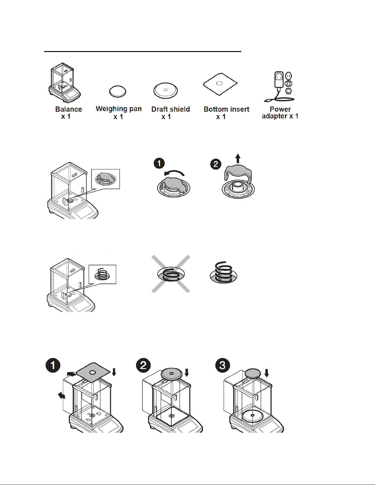
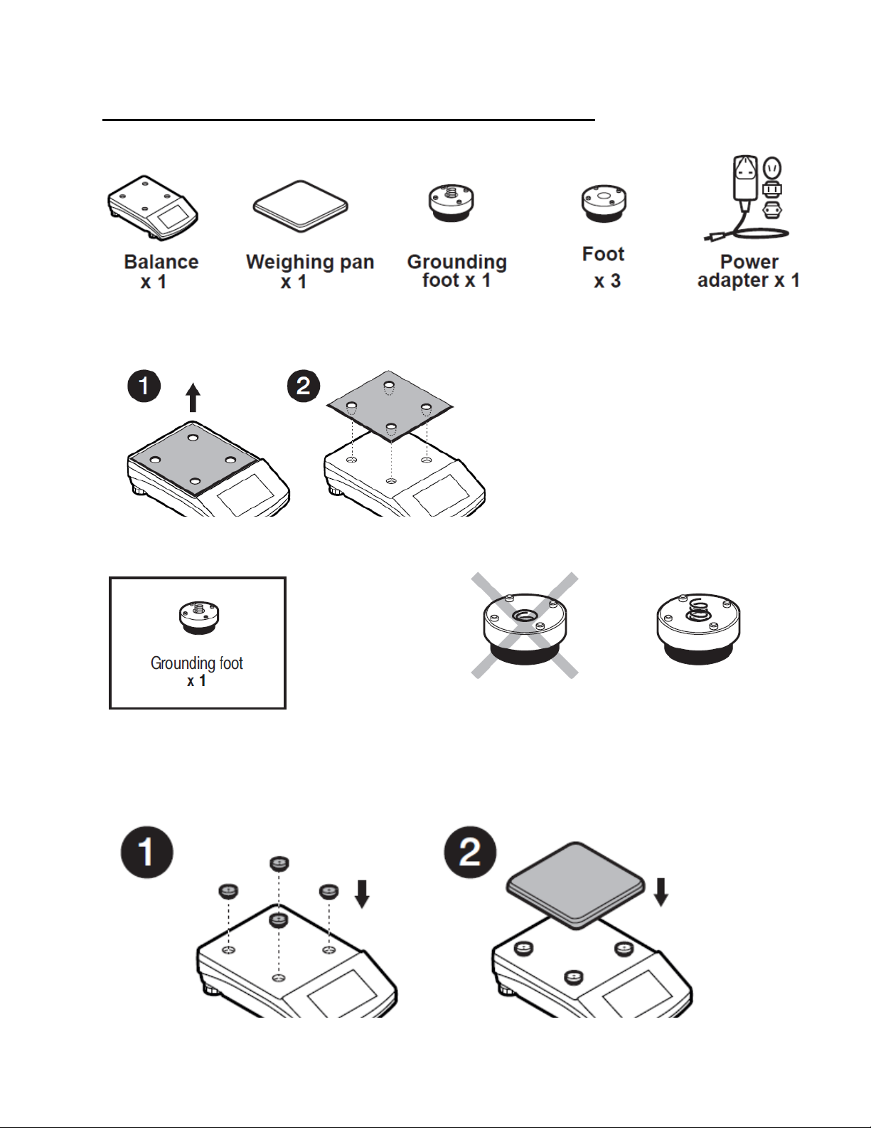
Model: TA-164.C, TA-224.C, TA-314.C, TA-164, TA-224, TA-314
Componets:
Installation:
1) Remove the transport lock– gently press the transport lock and turn it accordingly to
<OPEN>, keep the transport lock should your balance be transported in the future.
2) Check grounding spring to insure it is in the appropriate location. Make sure that the grounding
spring juts slightly out of the hole.
3) Install components following the diagram below:
i. Bottom insert
ii. Centering ring [embossment side up]
iii. Weighing pan
10
Page 11
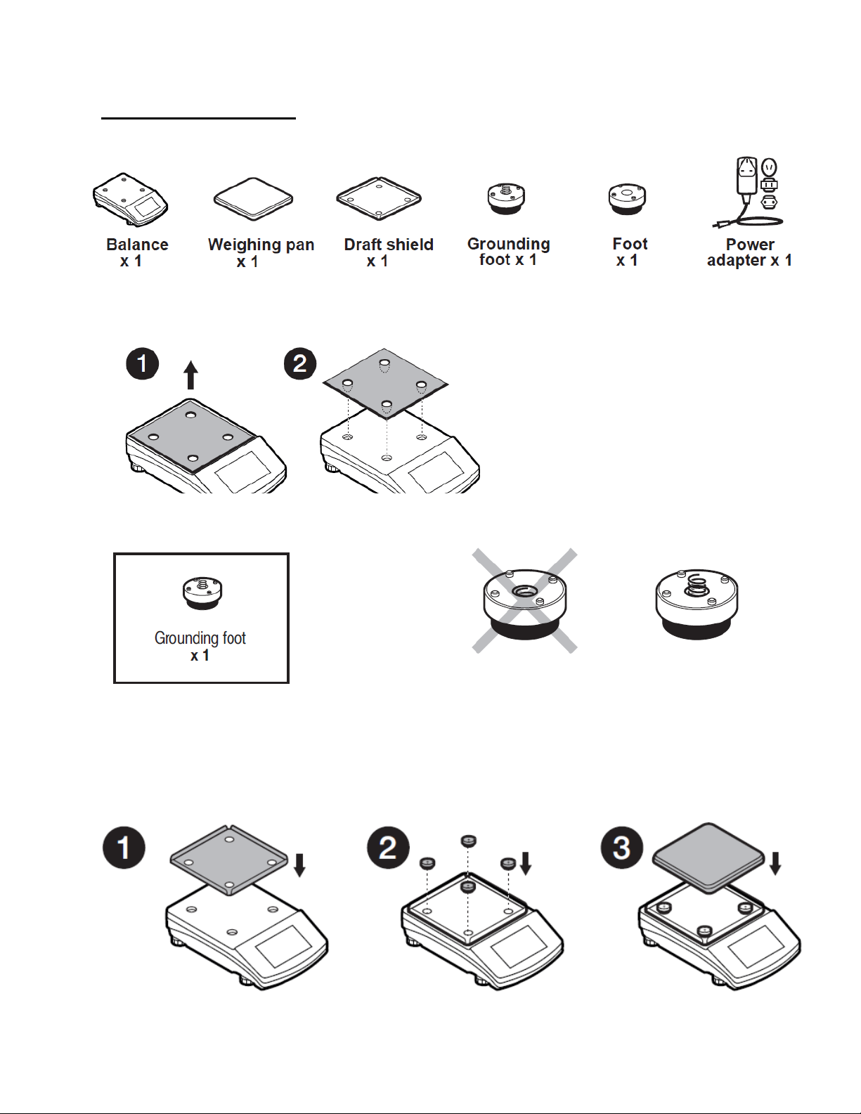
Model: TT-363.C, TT-603.C, TT-1003.C, TT-363, TT-603, TT-1003
Components:
Installation:
1) Remove transport lock, keep the transport lock should your balance be transported in the future.
2) Check that the grounding spring is in the correct location, the spring juts slightly out of the hole.
3) Install components following the diagram below:
i. Rubber feet (grounding foot can be in any location on the balance)
ii. Weighing pan
iii. Glas s draft shield
11
Page 12
Model: TT-2102.C, TT-4502.C, TT-2102, TT-4502, TT-6001, TT-10001
Components:
Installation:
1) Remove transport lock, keep the transport lock should your balance be transported in the future.
2) Check that the grounding spring is in the correct location, the spring juts slightly out of the hole.
3) Install components following the diagram below:
i. Rubber feet (grounding foot can be in any location on the balance)
ii. Weighing pan
12
Page 13
Model: TT-6002.C, TT-6002
Components:
Installation:
1) Remove transport lock, keep the transport lock should your balance be transported in the future.
2) Check that the grounding spring is in the correct location, the spring juts slightly out of the hole.
3) Install components following the diagram below:
i. Draft shield
ii. Rubber feet (grounding foot can be in any location on the balance)
iii. Weighing pan
13
Page 14
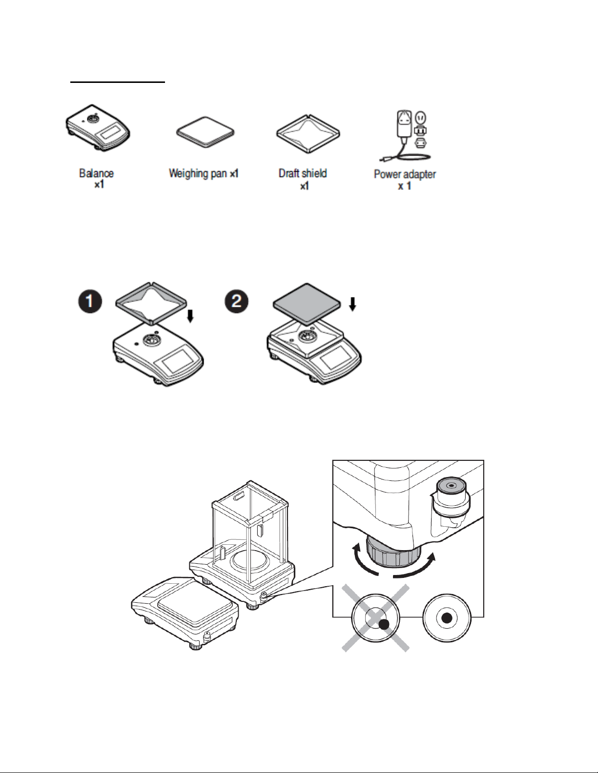
Model: TT-10102.C
Components:
Installation:
Install components following the diagram below:
i. Draft shield
ii. Weighing pan
2.5 BALANCE LEVELING
It is necessary to level the balance prior to plugging it in. To level the balance, turn its feet until the
air bubble is in the center position.
The balance should firmly rest on a surface, each of the feet must be supported.
14
Page 15
2.6 POWERING THE DEVICE
Before plugging in your balance, it is imperative to wait until the balance reaches thermal
stabilization.
For balances that were stored in much lower temperatures (e.g. during winter period), thermal
stabilization period will take at least 4 hours for Precision balances, and 8 hours for Analytical
balances.
• Balance should be plugged in only with the power adapter that comes standard with the
model. Nominal power supply of the power adapter (specified on the power adapter data
plate) should be compatible to the power supply.
• Plug the balance in – connect the power adapter to the socket, next connect its connector to
port located at the back of the balance housing.
• Press button located in the top right hand corner of the key pad.
! Remember to start the balance with no load on the weighing pan
• Wait u ntil the start-up procedure is completed. The home screen of balance software is
displayed automatically.
• If the indication is different than zero, please press button
3. BALANCE CONTROL
3.1 BALANCE KEYBOARD
15
Page 16
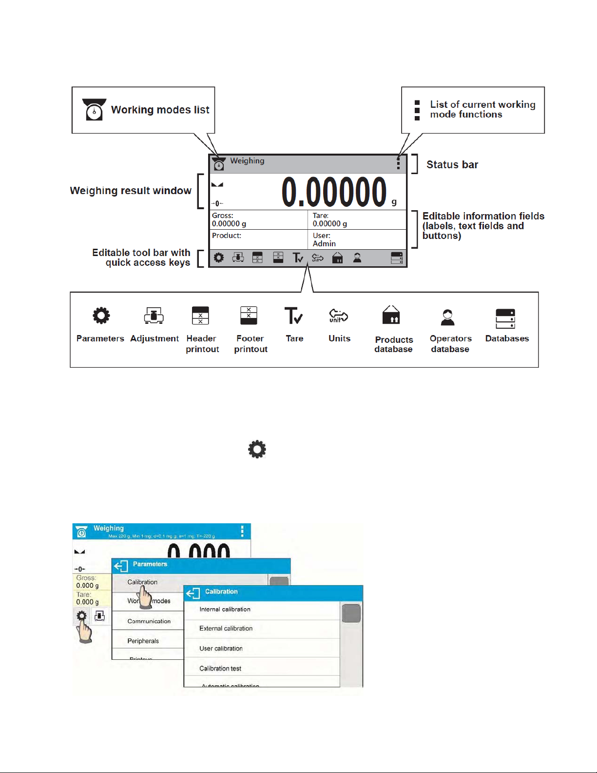
3.2 BALANCE HOME SCREEN
3.3 ENTERING BALANCE MENU
Operation of the balance menu is intuitive and easy to use. The touch panel makes the software
operation easy. Pressing a function key, a soft key or an area on the display initiates an assigned
function or process
To enter balance main menu, press < PARAMETERS> button. Clicking any button within this
section, or clicking any button with a parameter name, results in a change of color. This is for
signaling purposes. If a given area has any function or action assigned, then it is performed
automatically upon clicking (e.g. adjustment procedure), respectively a window with parameters or a
list of appropriate settings is displayed.
16
Page 17
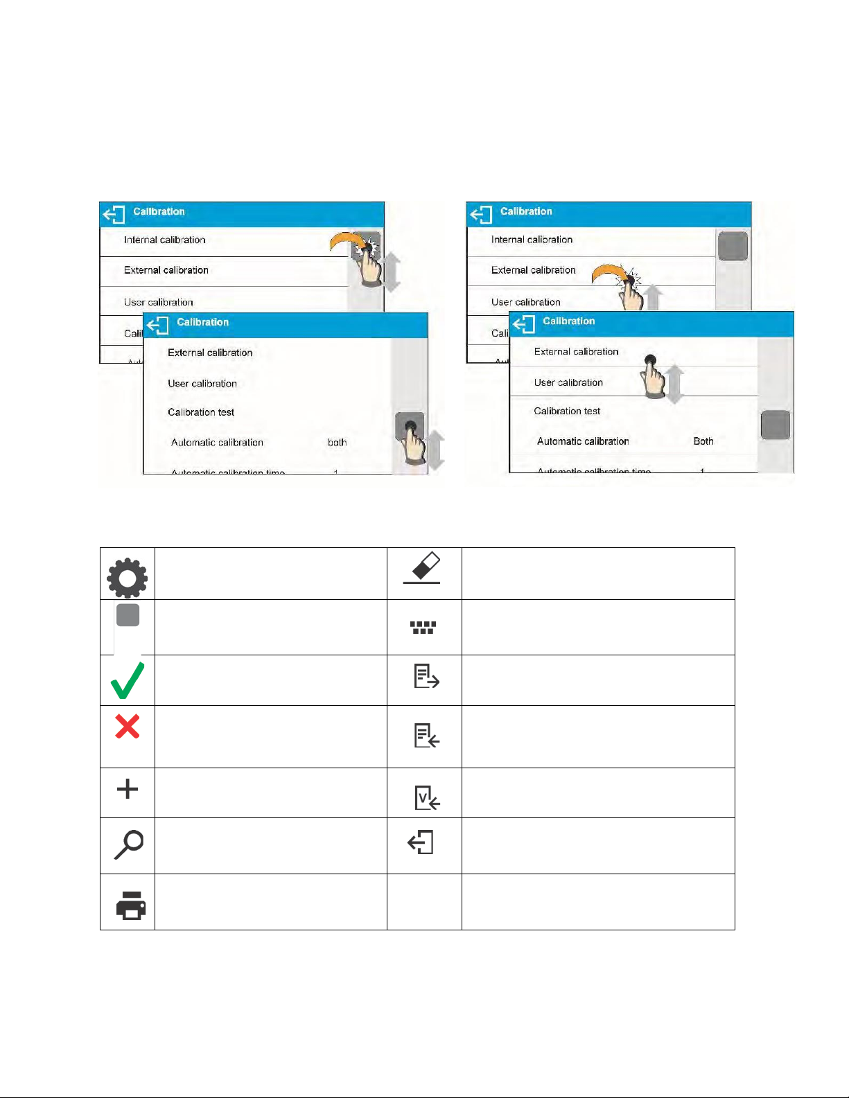
3.4 SCREEN SCROLLING
Press to enter the main menu.
Press to clear the editing field.
Press to scroll the menu “up”,
Press to enable / disable an on-
Press to confirm changes.
Press to export databases (key
drive).
Press to resign form introducing
Press to import databases (key
Press to add a new record to a
Press to select variables, out of the
Press to search for a record in a
Press to print out a record
There are two methods for scrolling the screen of parameters window. The first one requires
pressing, holding down and scrolling up or down the scrollbar located on the left. The second one
requires pressing, holding down and scrolling up or down on any point of the displayed window.
3.5 SOFT KEYS LIST
or “down”.
function modifications.
database.
database.
from a database.
screen keyboard.
active upon plugging a USB flash
active upon plugging a USB flash
drive).
list, for a printout.
Press to move (exit) one level up.
17
Page 18
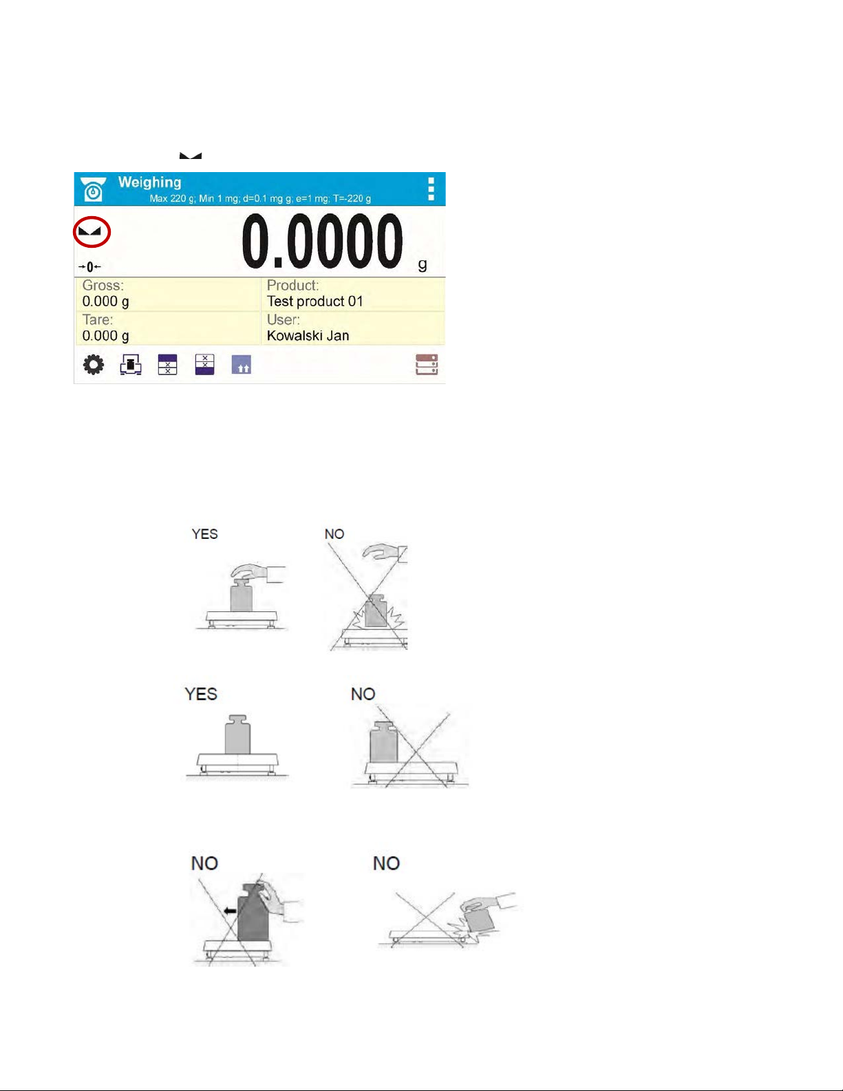
4. WEIGHING MODE
Load an object on the balance weighing pan. The stabilization of weighing result is indicated by a
stability marker visible on t he left side of balance display, read the measurement result.
4.1 GOOD WEIGHING PRACTICE
To ensure long lasting use of a balance with correct and reliable measurements of weighed loads,
follow the procedures below:
• Start the balance with no load on the weighing pan.
• Load the weighing pan carefully and avoid dropping it:
• Place weighed load in the center of the weighing pan:
• Avoid side loading, in particular side shocks:
18
Page 19
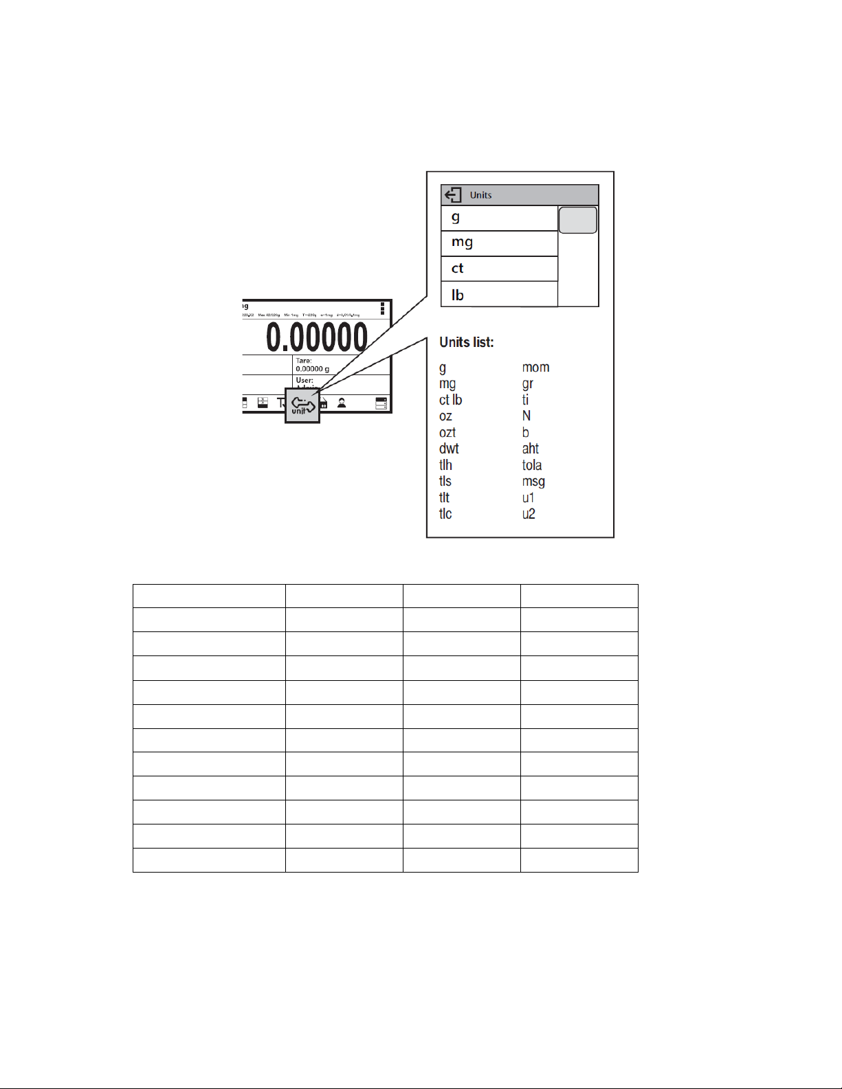
4.2 UNITS
Unit
Denotation
Unit
Denotation
To change the weighing unit, press the weighing unit icon. This brings up the available unit’s list,
choose new unit from the list displayed.
Units List:
gram [g] Taele China [tlc]
milligram [mg]
kilogram [kg]
carat [ct] Newton [N]
pound [lb]
ounce [oz] baht [baht]
ounce Troy [ozt]
pennyweight [dwt] mesghal [msg]
Taele Hongkong [tlh]
Taele Singapore [tls]
Taele Taiwan [tlt]
Momme [mom]
Grain [gr]
Tical [ti]
tola [tola]
User unit 1 [u1]
User unit 2 [u2]
19
Page 20
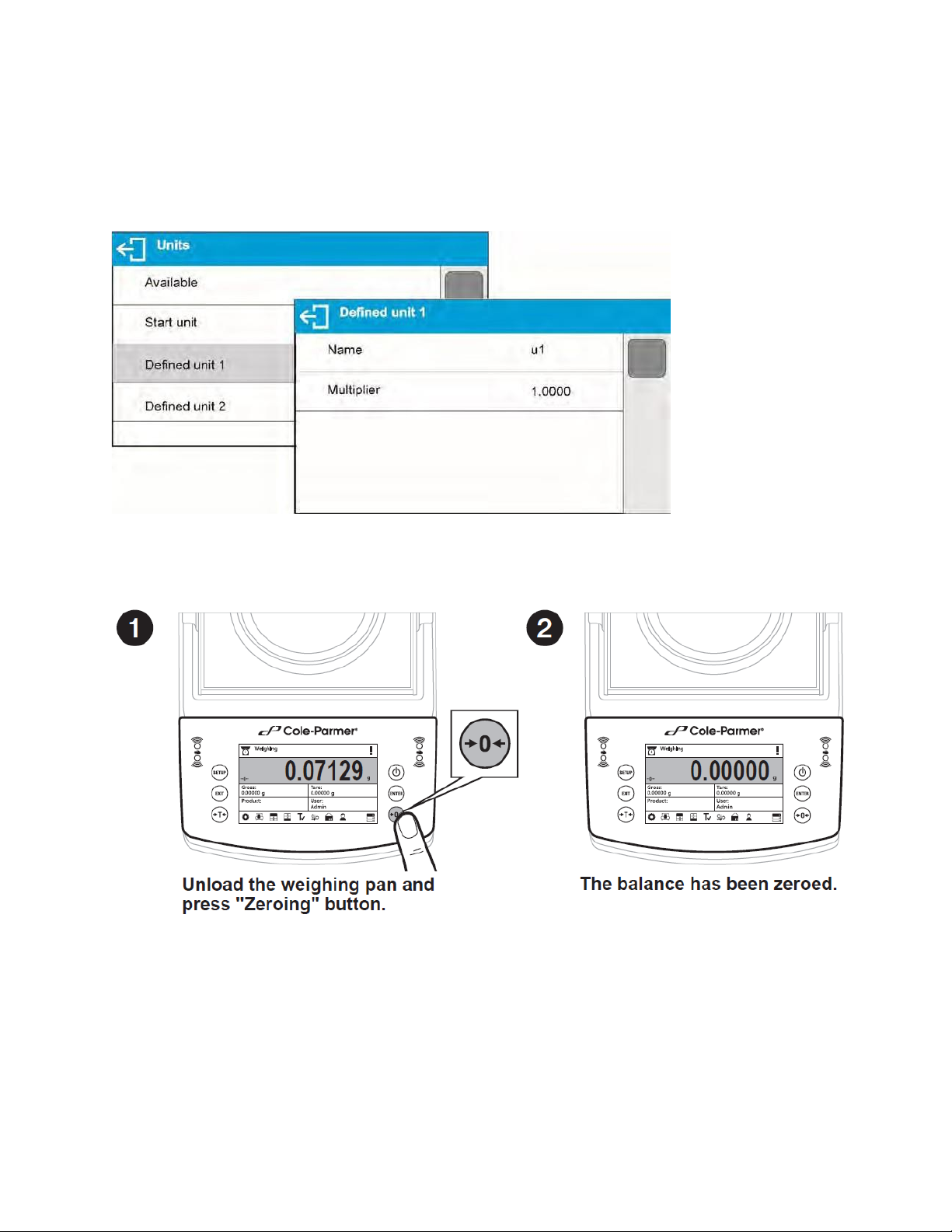
4.3 USER-DEFINED UNIT
You may create two custom user-defined units. Displayed value of a user-defined unit is a
multiplication of measured mass value and a coefficient specified for the user-defined unit. The units
can be freely named with use of 3 characters’ maximum. By default, the names are displayed as
[u1] – user unit 1, and [u2] – user unit 2.
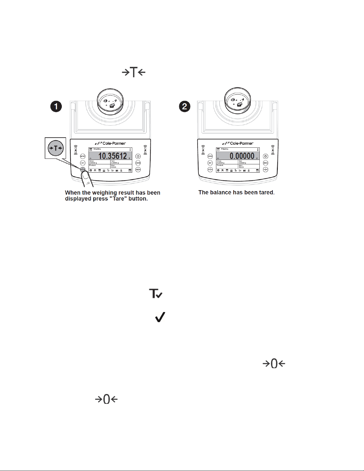
4.4 BALANCE ZEROING
Zeroing is a function allowing to zero mass indication.
The Zeroing process is an equivalent for determining new zero point, recognized by the balance as
precise zero. Zeroing is possible only for stable status of display indication.
! CAUTION
Zeroing the display indication is possible only within ±2% range of instrument’s maximum
capacity. If the zeroed value is above ±2% of the maximum capacity, then the balance
indicates a respective error message.
20
Page 21
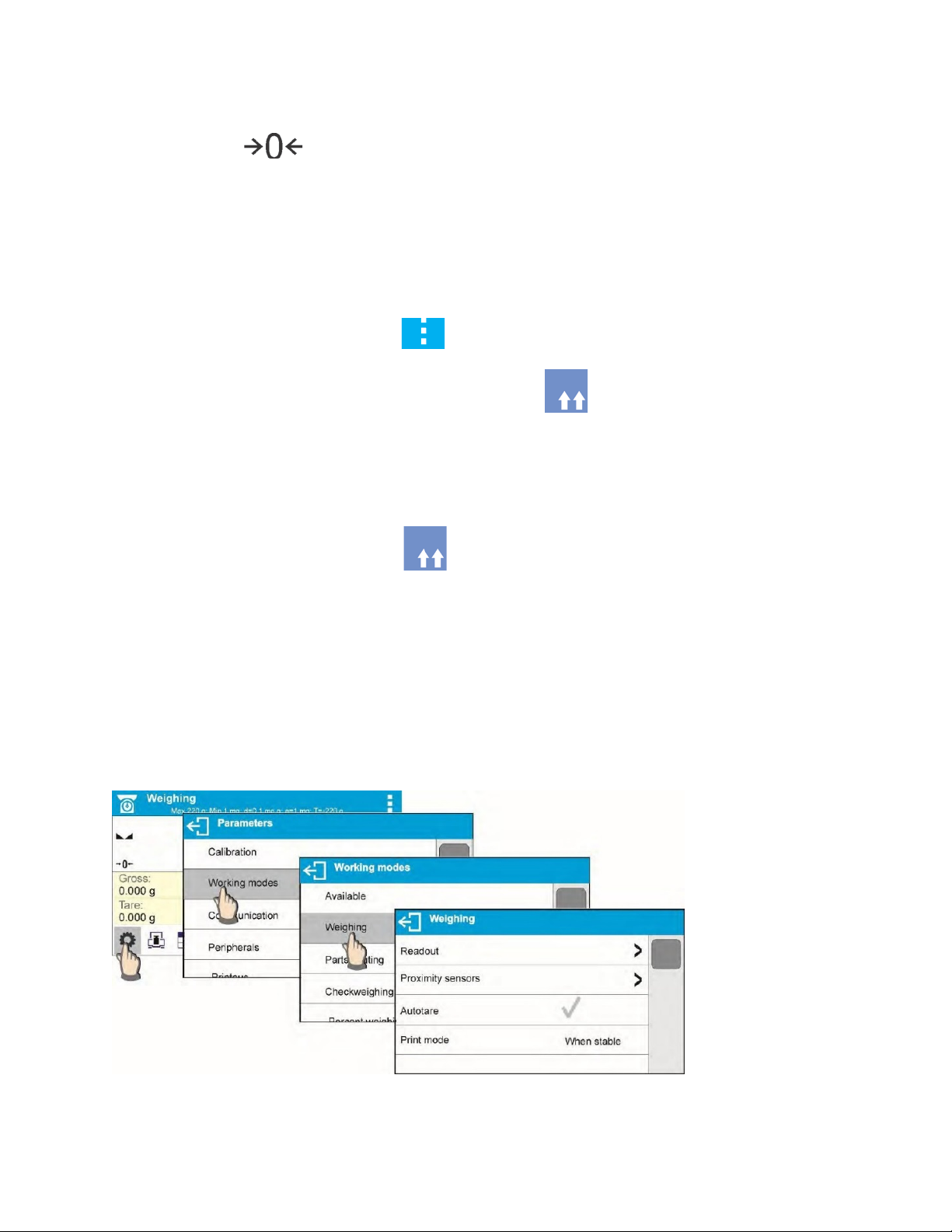
4.5 BALANCE TARING
Taring is a function allowing to determine net weight of a measured object. To determine net weight
of the object, place object’s container (packaging) on the weighing pan, and on stabilization of
measurement result press key.
The balance enables assigning tare value to a database-stored product. Using this option, the
software automatically uploads data on tare value for a product upon its selection from the
database.
! CAUTION
Taring negative values is impossible. On taring negative values, the balance responds with
an error message. In such case, zero balance indication and repeat taring procedure.
4.5.1 MANUAL TARE DETERMINATION
• Press quick access key
• An on-screen numeric keyboard is displayed
• Enter tare value and press key
• The balance returns to the weighing mode, and the display indicates entered tare value
with minus ‘–‘ sign
4.5.2 DELETING TARE
The tare value indicated on balance display can be deleted by pressing key on
balance overlay.
Procedure 1 - on taking the tared load off the weighing pan
• Press key.
• The NET marker is deleted, and new zero point of the balance is determined.
21
Page 22
Procedure 2 – with tared load on the weighing pan
• Press key.
• The NET marker is deleted, and new zero point of the balance is determined.
• When tare value exceeds 2% of the maximum capacity, respective message is
displayed to inform a user about the fact.
4.5.3 TARE DATABASE
Procedure-
• While in optional mode, press button located in a top right hand corner of the mass
display.
• Wait for a respective window to open, next select <PACKAGING>.
• Window with a list of tare values recorded into tare database opens.
• Select the packaging that is to be used.
• The balance returns to the weighing mode, and the display indicates selected tare value
with a minus ‘–‘ sign.
OR
• While in optional mode, press button (if displayed on the screen),
• Window with a list of tare values recorded into tare database opens.
• Select the packaging that is to be used.
• The balance returns to the weighing mode, and the display indicates selected tare value
with a minus ‘–‘ sign.
4.6 WEIGH MODE SETTINGS
The balance allows setup of operating parameters (filters, value release and autozero function,
deleting the last digit and other settings) separately for each working mode.
Procedure-
22
Page 23
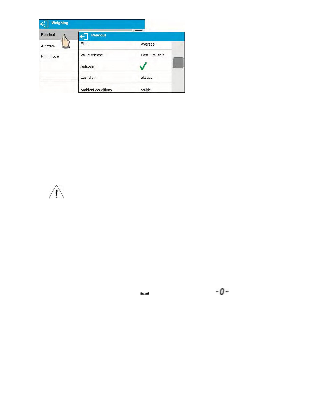
4.6.1 FILTER LEVEL SETTINGS
Filter settings adjustment depends on the working environment. For the best possible conditions
the filter can work in a very fast mode (V.FAST value for Filter parameter); however, if the
conditions are poor (shakes, drafts), the filter should be set to slow or very slow option (SLOW
or V. SLOW value for Filter parameter). The effectiveness of the filter is different throughout the
weighing range. The filter works slower when “approaching” the weighed mass, it works more
quickly for weighed mass within the set range of the filter (parameter for setting filter range is
accessible only from the service menu – the user does not have any access to it).
Depending on the filter, the weighing time is shorter (V.FAST and FAST) or longer (SLOW and
V. SLOW).
CAUTION!
The higher filter level, the longer the weighing time.
4.6.2 VALUE RELEASE
Since ambient conditions at a workplace vary, it is necessary to determine the value release
parameter that are best for your working environment, parameter options are: FAST.+REL.,
FAST or RELIABLE. Depending on the selected option, weighing time is either shorter or
longer.
4.6.3 AUTOZERO FUNCTION
The balance features an autozero function (Auto). This function automatically controls and
corrects the zero reading. When Autozero is enabled, it compares balance readings at declared
time interval e.g. 1s, if weighing pan is unloaded and display indication is close to zero. If results
vary less than declared AUTOZERO range e.g. one division, balance zeroes automatically,
marker of stable measurement result , and precise zero marker are displayed.
If AUTOZERO function is enabled, then each weighing process starts from precise zero point.
There are, however, some instances when this function can be a disturbing factor for the
measuring process; e.g. very slow placing of a load on the weighing pan (load adding). Here,
zero reading correction can also correct the actual reading of loaded mass.
23
Page 24

4.6.4 LAST DIGIT DISPLAY
Function enables displaying the last digit of decimal place for a weighing result. There are three
available options:
• Always: all digits visible
• Never: last digit is not displayed
• When stable: last digit is displayed only for a stable weighing result
4.6.5 BALANCE AMBIENT CONDITIONS
Parameter relating to ambient and environmental conditions in which the balance operates.
There are two options: STABLE and UNSTABLE. Selecting STABLE mode makes the balance
work much faster, i.e. weighing takes much less time than for UNSBABLE mode. If the ambient
conditions are unstable it is recommended to use UNSTABLE mode. By default, the parameter
is set to STABLE option.
5. ADJUSTMENT (TA.C AND TT.C SERIES)
To ensure the highest weighing accuracy, it is recommended to periodically introduce a corrective
factor of indications to balance memory, the said factor must be referred to a mass standard. In other
words, balance adjustment shall be performed from time to time.
Adjustment should be carried out:
• Before the beginning of weighing procedure
• If long breaks between following measuring series occur
• If temperature inside the balance changes more than: 1°C or 2°C for Analytical balances or 2°C
for Precision series balances.
Types of adjustment:
• Automatic adjustment (automatic or manual)
• External adjustment
• User defined adjustment- external weight of declared mass which cannot be modified or of any
mass, but not lower than 30% of maximum range.
5.1 INTERNAL ADJUSTMENT
Internal adjustment can be triggered in two fashions, automatically or manually by the user.
5.1.1 AUTOMATIC ADJUSTEMENT
This menu is for declaring a value initiating an automatic internal adjustment. Accessible
options:
• None – automatic adjustm ent disabled
• Time – adjustment takes place in time intervals declared in menu <Automatic adjustment
time>. The time interval is declared in hours and ranges between 0.5 and 12 hours.
• Temperature – adjustment is triggered by temperature change only
• Both – adjustment is triggered by both, temperature changes and time.
CAUTION!
Parameter settings can be modified only for balances that are not a subject to conformity
assessment (verification).
24
Page 25

5.1.2 MANUAL INTERNAL ADJUSTMENT
Internal adjustment is carried out with of an internal adjustment weight. button, when
pressed, automatically triggers adjustment process. Upon adjustment process completion,
respective message informing about process end and about its status is displayed.
CAUTION!
Adjustment procedure requires stable environmental conditions (no air drafts or ground
vibrations). The process must be carried out with an empty weighing pan.
5.2 EXTERNAL ADJUSTMENT
External adjustment is carried out by means of an external mass standard of specified accuracy
class and weight. Both, accuracy class and mass standard weight depend on balance type and max
capacity. The process takes semi-automatic form; successive stages are signaled with prompts.
Procedure-
• Enter <Adjustment> submenu, next select “External adjustment” option,
• “Remove weight” prompt is displayed.
• Take the weight off the weighing pan and press button. Whereas balance
determines start mass, “Adjustment; Please wait…” prompt is displayed,
• Upon completed start mass determination procedure “Put weight …” prompt is displayed
along with particular mass standard value.
• Put the required weigh on a pan and press button,
• Upon completed procedure “Remove weight” prompt is displayed.
• Take the weight off the weighing pan, wait for <Adjustment> window to be displayed
again.
5.3 USER ADJUSTEMENT
An external calibration process can be carried out with an external mass standard of defined value
by the user. The calibration mass must be at a value greater than 30% of the balances Max range
Procedure-
• Enter <Adjustment> submenu, next select “User adjustment” option,
• Type in calibration weight to be utilized (must be at a value greater than 30% of
balances max range)
• Press button.
• The balance prompts you to “Remove weight”, with weighing pan clear press button
• Put the required weigh on a pan and press button,
• Upon completed procedure “Remove weight” prompt is displayed.
• Take the weight off the weighing pan, wait for <Adjustment> window to be displayed
again.
25
Page 26

5.4 ADJUSTM E NT TE S T
<Adjustment test> function enables comparing the result of an internal automatic adjustment with
the value recorded in balance factory parameters. The comparison is used for determining balance
sensitivity drift over time.
6. ADJUSTMENT (TA AND TT SERIES)
To ensure the highest weighing accuracy, it is recommended to periodically introduce a corrective
factor of indications to balance memory, the said factor must be referred to a mass standard. In other
words, balance adjustment shall be performed from time to time.
Adjustment should be carried out:
• Before the beginning of weighing procedure
• If long breaks between following measuring series occur
• If temperature inside the balance changes more than: 1°C or 2°C for Analytical balances or 2°C
for Precision series balances.
Types of adjustment:
• External adjustment
• User defined adjustment- external weight of declared mass which cannot be modified or of any
mass, but not lower than 30% of maximum range.
6.1 EXTERNAL ADJUSTMENT
External adjustment is carried out by means of an external mass standard of specified accuracy
class and weight. Both, accuracy class and mass standard weight depend on balance type and max
capacity. The process takes semi-automatic form; successive stages are signaled with prompts.
Procedure-
• Enter <Adjustment> submenu, next select “External adjustment” option,
• “Remove weight” prompt is displayed.
• Take the weight off the weighing pan and press button. Whereas balance
determines start mass, “Adjustment; Please wait…” prompt is displayed,
• Upon completed start mass determination procedure “Put weight …” prompt is displayed
along with particular mass standard value.
• Put the required weigh on a pan and press button,
• Upon completed procedure “Remove weight” prompt is displayed.
• Take the weight off the weighing pan, wait for <Adjustment> window to be displayed
again.
26
Page 27
6.2 USER ADJUSTEMENT
Weighing
balance measures gravitational force which attracts the load. An obtained result is
in a form of measurement result. More
Parts Counting
information found in Section 9.
Dosing
Percent Weighing
Means of operation: control of percent ratio of a sample in relation to a standard
Density of solids
Density of liquids
An external calibration process can be carried out with an external mass standard of defined value
by the user. The calibration mass must be at a value greater than 30% of the balances Max range
Procedure-
• Enter <Adjustment> submenu, next select “User adjustment” option,
• Type in calibration weight to be utilized (must be at a value greater than 30% of
balances max range)
• Press button.
• The balance prompts you to “Remove weight”, with weighing pan clear press button
• Put the required weigh on a pan and press button,
• Upon completed procedure “Remove weight” prompt is displayed.
• Take the weight off the weighing pan, wait for <Adjustment> window to be displayed
again.
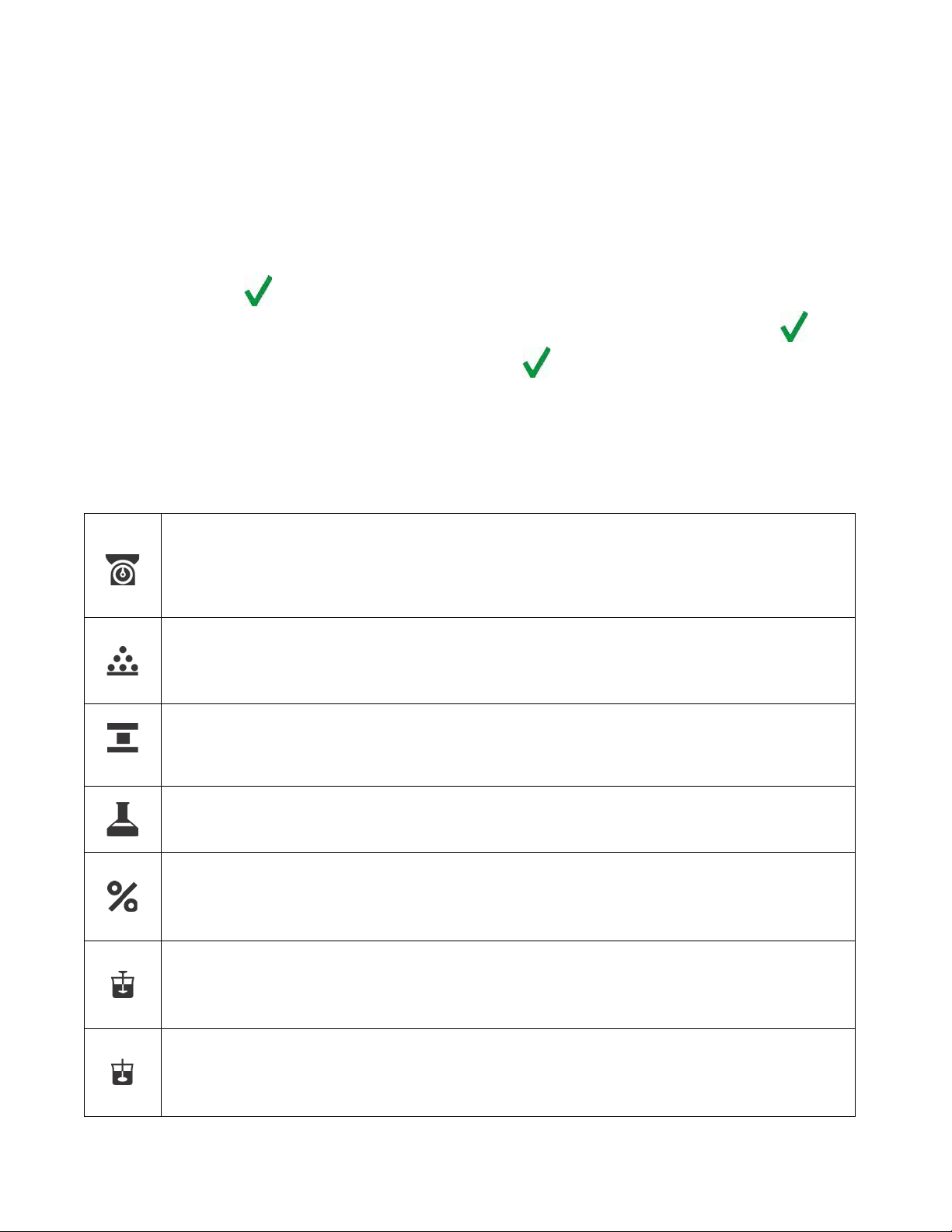
7. WORKING MODES- GENERAL INFORMATION
The balance features the following working modes:
Means of operation: weight of a load is determined through an indirect measurement. A
processed to a digital format and displayed
information found in Section 4.
Means of operation: based on a determined mass of a single part it is possible to count
another part, if the mass of the single part is determined with sufficient accuracy, and that
the following parts are equal in mass. More information found in Section 8
Check Weighing
Means of operation: control of sample mass with applied thresholds. A user should
specify the value of min threshold <LO> and max threshold <HI>. More
Means of operation: a user should specify sample’s target mass to be obtained by
pouring. More information found in Section 10.
(reference). Obtained data provides percent ratio on how test sample differs from the
accepted standard (reference). More information found in Section 11.
Means of operation: based on Archimedes principle, a balance determines density of
solids. The mode requires an optional density determination kit. More information
found in Section 12.
Means of operation: based on Archimedes principle, a balance determines density of
liquids. The mode requires an optional density determination kit. More information
found in Section 13.
27
Page 28
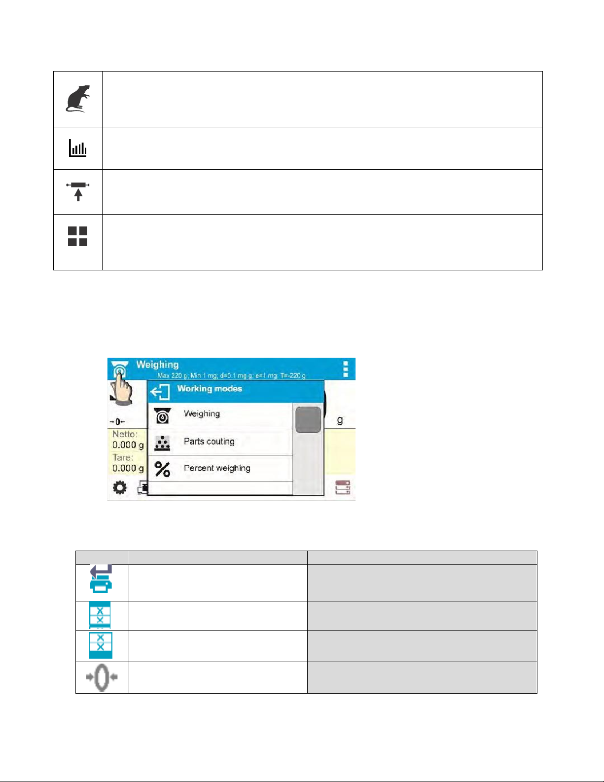
Animal Weighing
Means of operation: mass measurement takes place with application of filters dampening
Statistics
Peak Hold
Formulations
Key
Function
Modes featuring the key
animal moves on a weighing pan, thus enabling obtaining a correct measurement result.
More information found in Section 14.
Means of operation: carried out measurements are used to calculate statistical data, such
as Min, Max, deviation, etc. More information found in Section 15.
Means of operation: max temporary indication occurring in course of the weighing
process is hold on a display. More information found in Section 16.
Means of operation: by mixing specified ingredients you can obtain particular mixture, in
order to program given formulation you have to specify weight of particular ingredients.
More information found in Section 17.
7.1 RUNNING WORKING MODE
To run working mode other than the one currently operating:
• Press pictogram of currently used working mode, the pictogram is in the top left hand
corner
• Wait for the available working modes list to be displayed
• Select the working mode you need to operate.
7.2 QUICK ACCESS KEYS FOR EACH WORKING MODE
Accept/Print
All modes
Print header All modes
Print footer
All modes
Zero All modes
28
Page 29
All modes (Parts Counting and Percent
All modes (Parts Counting and Percent
All modes (Parts Counting and Percent
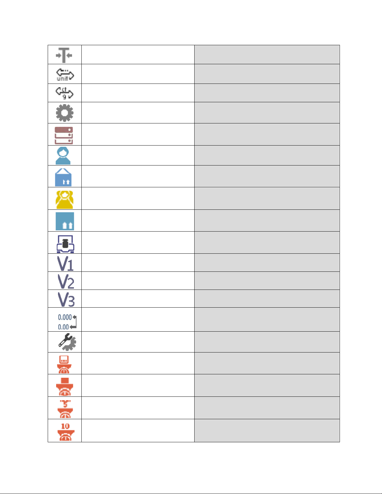
Tare All modes
Change unit
Select unit
Weighing modes excluded)
Weighing modes excluded)
Parameters All modes
Databases All modes
User All modes
Product
Customer
All modes
All modes
Packaging All modes
Adjustment All modes
Variable 1 All modes
Variable 2 All modes
Variable 3 All modes
Hide/show last digit
Working mode parameters All modes
Set part mass
Determine part mass
Determine mass using 5 parts
Determine mass using 10 parts Parts Counting mode exclusively
Weighing modes excluded)
Parts Counting mode exclusively
Parts Counting mode exclusively
Parts Counting mode exclusively
29
Page 30
Solids and Liquids Density modes and
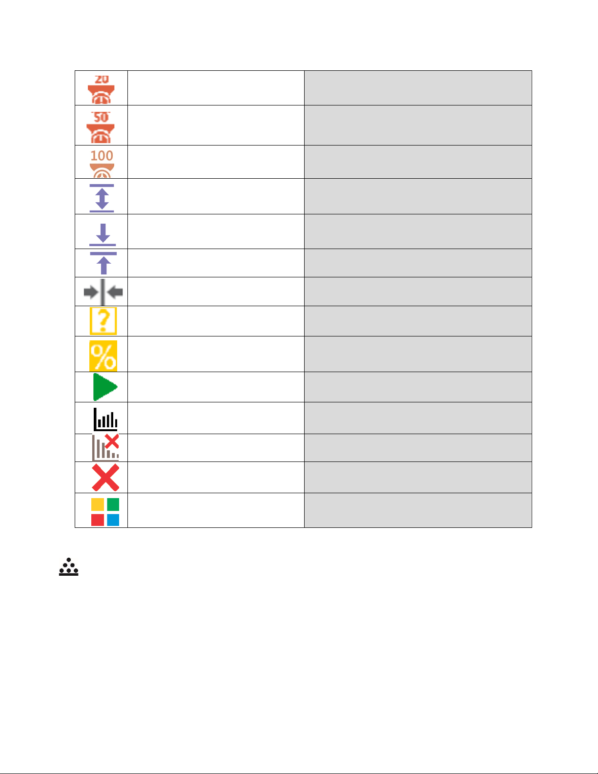
Determine mass using 20 parts
Parts Counting mode exclusively
Determine mass using 50 parts
Parts Counting mode exclusively
Determine mass using 100 parts Part s Counting mode exclusively
Thresholds Check weighing mode exclusively
Min threshold Check weighing mode exclusively
Max threshold Check weighing mode exclusively
Target value Dosing mode exclusively
Set reference mass
Determine reference mass (set
as 100%)
Start
Percent Weighing mode
exclusively
Percent Weighing mode
exclusively
Formulations mode
Results St atistics mode exclusively
Finish Statistics mode exclusively
Finish Peak Hold mode exclusively
Formulation Formulations mode exclusively
8. PARTS COUNTING
< Parts counting> is a working mode which enables determination of quantity of small parts with
equal weight. Determined mass of a single part is used for the counting procedure. The single part
mass may be:
• Determined from a reference quantity of parts subjected to weighing,
• Acquired from database of products,
• Entered manually as a numeric value.
30
Page 31

Procedure for activation of Parts Counting mode
Select < Parts counting> mode, home screen featuring parts counting pictogram in a top bar
is automatically displayed.
Info field provides the following information:
• Gross weight
• Tare weight
• Net weight
• Part mass
• Product
• User
8.1 SUPPLEMENTARY SETTINGS FOR P ARTS COUNTI NG MODE
The supplementary settings enable adjusting the working mode to your needs and requirements.
ACAI, Automatic Accuracy Correction, provides the following options:
• YES, single part mass is updated
• NO, single part mass is not updated
Means of operation of ACAI function:
1. Number of pieces (on adding) on balance weighing pan has to be greater than before.
2. Number of pieces (on adding) on balance weighing pan must be less than twice the
amount displayed before adding the pieces.
3. Curr ent quant ity of parts must be within ± 0,3 tolerance of the total value.
4. Measurement result has to be stabilized.
Procedure-
31
Page 32

8.2 PARTS COUNTING – QUICK ACCESS KEYS
Each working mode features automatically displayed set of default quick access keys. The set can
be modified by assigning out-of-list quick access keys to on-screen keys. Such operation requires
particular permissions level.
Default Quick Access Keys: parameters, adjustment, print header, print footer, set part mass,
determine part mass (from a reference quantity of parts), determine mass using 10 parts, product,
user, databases.
8.3 PARTS COUNTING PROCEDURE
The first step for Parts Counting mode is obtaining data on mass of a single part. Select one of
available options:
• Give weight value of a single part and put parts to be counted on the weighing pan,
balance displays totalized parts.
• Determine mass of a single part from a given quantity of parts. Put parts to be counted
on the weighing pan, the balance displays totalized parts. In course of calculation, ACAI
function pictogram > is displayed (providing the function is active).
• Acquire mass of a single part from database of products by selecting a desired product
record. Put parts to be counted on the weighing pan, the balance displays totalized
parts.
CAUTION!
Any additional elements (packaging) shall be tared prior to counting process start.
With single part mass set, put parts to be counted into tare container weight of which has been
stored by balance memory.
Number of weighed pieces is displayed on a screen.
Stable measurement (stability pictogram displayed) can be printed. To do it press button,
please note a printer must be connected to perform this action.
32
Page 33

8.4 SETTING REFERENCE BY ENTERING DETERMINED PART MASS
Procedure-
• Press Set part mass> key or the label , <Part mass> editing
window featuring an on-screen keyboard is displayed,
• Enter the requested value and confirm by pressing key, <Parts counting> mode is
run with automatically specified part mass.
CAUTION!
If you enter weight of value that is lower than 0.1 reading unit, then <Value too low>
message is displayed.
8.5 SETTING REFERENCE MASS BY DETERMINING PART MASS
Procedure-
• Put a container on a weighing pan, tare its mass,
• Press < Determine part mass> button, <Reference quantity> editing
window featuring an on-screen keyboard is displayed,
• Enter the requested value and confirm by pressing key,
33
Page 34

•
Message on number of parts to be loaded is displayed: <Number of parts to be loaded:
18>,
• Put specified number of pieces on the weighing pan, when the result is stable ( stability
pictogram displayed) press k ey to confirm
• The balance automatically recalculates single part mass, next it moves to <Parts counting>
mode displaying number of parts loaded on the weighing pan (pcs marking).
34
Page 35

CAUTION!
It is important to remember the following:
• Total mass of all parts loaded on the weighing pan must not exceed the maximum
capacity (weighing range) of the balance;
• Total mass of all parts loaded on the weighing pan must not be lower than value
declared in parameter “Minimal reference mass”. Unless this condition is met,
the balance displays a message: <Sample mass too low>;
• Mass of a single part must not be lower than 0,1 of balance reading unit. Unless
this condition is met, the balance displays a message: <Single part mass too
low>.
8.6 ACQUIRING PART MASS FROM A DATABASE
Each product recorded in a database of products features a set of information which allows it to be
identified by. Among the information there is mass value used during part counting process.
Procedure-
Operating <Parts counting> mode, press < Product> button and using the list select a
particular product. The program returns to <Parts counting> mode with single part weigh value set
automatically on the basis of data recorded for a selected product.
Entering reference mass to balance memory
Procedure for entering single part mass to products database:
• Press < Databases> button,
• While in database press <Products> button,
• Press button (add product), located in the top bar,
• Fill in fields referring to product (Name, Code, EAN, Mass – for Parts Counting mode it is
single part weight),
• Return to <Parts counting> mode.
35
Page 36

9. CHECKWEIGHING
< Checkweighing> is a working mode using two thresholds (Min and Max) for control of samples
weight. Usually the weight is considered to be correct if it is comprised within threshold values.
Procedure for activation of checkweighing mode
Select < Checkweighing> mode, home screen featuring checkweighing pictogram in a top
bar is automatically displayed.
Info field provides the following information:
• Bar graph with checkweighing thresholds
• Gross weight
• Tare weight
• User
9.1 SUPPLEMENTARY SETTINGS FOR CHECKWEIGHING MODE
The supplementary settings enable adjusting the working mode to your needs and requirements.
For means of operation of these functions read section 4.6 “WEIGH MODE SETTINGS”.
You can place the bar graph within information field area. Below the bar graph, Min and Max
threshold values are displayed.
9.2 CHECKWEIGHING – QUICK ACCESS KEYS
Each working mode features automatically displayed set of default keys. The set can be modified
by assigning out-of-list quick access keys to on-screen keys. Such operation requires particular
permissions level.
Default Quick Keys: parameters, adjustment, print header, print footer, specify checkweighing
thresholds, product, user, databases.
9.3 MAKING USE OF CHECKWEIGHING THRESHOLDS
In order to use checkweighing thresholds:
• Select <Product Database > with Min and Max threshold declared
• Enter numerical value for the thresholds using > or > or > button, in this
case thresholds do not refer to any product.
36
Page 37

Procedure 1 – selecting product from Products Database
• Press < Products Database> key.
• Using product list, select the product that is to be weighed.
• The balance displays threshold values under the bar graph within INFO area. Bar graph
color corresponds to the current status of weight:
• Yellow color: weight value below Min threshold value
• Green color: weight value within set threshold values
• Red color: weight value above Max threshold value
Procedure 2 – entering checkweighing thresholds manually
• Press < Checkweighing Thresholds> button,
• Window with an on-screen numeric keyboard is displayed, use it to enter Min threshold
value,
• Press < > button for confirmation,
• Window with an on-screen numeric keyboard is displayed, use it to enter Max threshold
value,
• Press < > button for confirmation,
• Home screen of the mode is displayed with entered threshold values.
CAUTION!
Max threshold value has to be greater than Min threshold value.
37
Page 38

For thresholds value modification the following buttons are used:
• - Min threshold value modification, enter the new value using an on-screen
numeric keyboard, next press < > button for confirmation. Upon confirmation, home
screen of checkweighing mode is automatically displayed.
• - Max threshold value modification, enter the new value using an on-screen
numeric keyboard, next press < > button for confirmation. Upon confirmation, home
screen of checkweighing mode is automatically displayed.
10. DOSING
< Dosing> is a working mode for performance of sampling process, wherein the sampling takes
as long as it is necessary to obtain pre-defined target weight.
Procedure for activation of dosing mode
Select < Dosing> mode, home screen featuring dosing pictogram in a top bar is
automatically displayed.
Info field provides the following information:
• Bar graph with target value
• Net weight
• Tare weight
• User
10.1. SUPPLEMENTARY SETTINGS FOR DOSING MODE
The supplementary settings enable adjusting the working mode to your needs and requirements.
For means of operation of these functions read section 4.6 “WEIGH MODE SETTINGS”.
You can place the bar graph within information field area. Below the bar graph, Min and Max
threshold values are displayed.
10.2 DOSING – QUICK A CCESS KEYS
Each working mode features automatically displayed set of default keys. The set can be modified
by assigning out-of-list quick access keys to on-screen keys. Such operation requires particular
permissions level.
38
Page 39

Default Quick Access Keys: parameters, adjustment, print header, print footer, specify target value,
product, user, databases
10.3 MAKING USE OF PRODUCTS DATABASE FOR DOSING OPERATION
The operator can use target value assigned to a product or values recorded in Product Database.
Additionally, option of user-defined temporary target values is at user disposal. Mass field is the
target value for Product Database.
Procedure 1 – selecting product from Products Database
• Press < Products Database> button.
• Using product list, select the product that is to be weighed.
• Target and tolerance values are displayed automatically within bar graph area.
• Target value with minus sign is displayed
• The balance displays threshold values under the bar graph within INFO area.
• Bar graph color corresponds to the current status of weight:
Yellow color: weight value below Target Value - Tolerance
Green color: weight value within tolerance, Target Value +/- Tolerance
Red color: weight value above Target Value + Tolerance
39
Page 40

Procedure 2 – target value entered manually
• Press < Target Value> button,
• Window with an on-screen numeric keyboard is displayed, use it to enter the target value,
• Confirm the entered value,
• Window with an on-screen numeric keyboard is displayed again, use it to enter the sampling
tolerance value,
• Confirm the entered value, home screen of the mode is displayed.
11. PERCENT WEIGHING
< Percent weighing> is a working mode for comparison of a measured sample with the reference
mass. The result is expressed in [%].
Procedure for activation of Percent Weighing mode
Select < Percent Weighing> mode, home screen featuring percent weighing pictogram in a
top bar is automatically displayed.
Info field provides the following information:
• Gross weight
• Tare weight
• Net weight
• Reference mass
• Product
• User
11.1. SUPPLEMENTARY SETTINGS FOR PERCENT WEIGHING
The supplementary settings enable adjusting the working mode to your needs and requirements.
For means of operation of these functions read section 4.6 “WEIGH MODE SETTINGS”.
You can place the bar graph within information field area. Below the bar graph, Min and Max
threshold values are displayed.
11.2 PERCENT WEIGHING – QUICK ACCESS KEYS
Each working mode features automatically displayed set of default keys. The set can be modified
by assigning out-of-list quick access keys to on-screen keys. Such operation requires particular
permissions level.
40
Page 41

Default Quick Access Keys: parameters, adjustment, print header, print footer, set reference mass,
determine reference mass (set as 100%), product, user, databases.
11.3 COMPARISON OF SAMPLE OF REFERENCE MASS
Comparison of samples and reference mass can be carried out by means of:
• < Set reference mass> button used for entering reference mass value
• < Determine reference mass (set as 100%)> button used for accepting current
mass loaded on a weighing pan as a reference mass,
• <Product> button used for selecting a product, out of products database, for which mass
parameter has been defined.
Procedure 1 – determining reference mass manually
• Press < Set reference mass > button.
• Using an on-screen keyboard of a displayed window, enter reference mass value and press
< > button for confirmation.
• Mass of all weighed products is compared to reference mass, the weight difference is
displayed in [%].
Procedure 2 – accepting currently loaded mass as reference mass
• Put the sample on a weighing pan.
41
Page 42

• On measurement result stabilization, press< Determine reference mass (set as
100%)> button, dialog bar with prompts is displayed at the bottom, follow the prompts.
• Load the part to be weighed and upon measurement stabilization press button for
confirmation,
• 100.000% indication is displayed, loaded part weight is accepted as a reference mass, it is
automatically recorded and displayed in reference mass field.
• Remove the sample form the weighing pan.
• All samples weighed afterwards are compared with the reference mass, and the display
indicates the difference, expressed in [%], for each weighed sample in relation to the
reference mass
42
Page 43

Procedure 3 – selecting product from Products Database
• Press < Product> button, using displayed product list select the product that is to be
weighed.
• Info” field automatically displays new information on reference mass and product.
• Reference mass relating to the product is recorded automatically and displayed in reference
mass field.
• 0.000 % indication is displayed (for unloaded pan).
• All samples weighed afterwards are compared with the reference mass, and the display
indicates the difference, expressed in [%], for each weighed sample in relation to the
reference mass
12. DENSITY OF SOLIDS
< Solids density> is a working mode enabling determination of density of a representative sample
material.
In order to operate this mode, an optional Density Determination Kit (additional information located in
Section 26.1) is available for purchase. For the measurement an appropriate model of the kit is used
for the balance depending on pan configuration. Prior to installing the kit, it is necessary to remove the
weighing pan and a draft shield.
Procedure for activation of Solids Density mode
Select Solids Density> mode, home screen featuring solids density pictogram in a top bar is
automatically displayed.
43
Page 44

Info field provides the following information:
• Weighing in air
• Weighing in liquid
• Liquid
• Liquid density
• Temperature
• User
12.1 SUPPLEMENTARY SETTINGS FOR SOLIDS DENSITY MODE
The supplementary settings enable adjusting the working mode to your needs and requirements.
• Liquid
Parameter allowing to specify liquid used for measurement performance:
Water/Ethanol/Other.
• Liquid density
Parameter allowing to enter density of liquid used for measurement performance. This
parameter is operable only when OTHER option for LIQUID parameter has been selected.
• Temperature
Parameter allowing to enter temperature of liquid used for measurement performance.
Temperature value is necessary in order to take the right liquid density value needed for
density calculation.
Balance stores tables with density of water and ethanol in relation to temperature.
12.2. SOLIDS DENSITY – QUICK ACCESS KEYS
Each working mode features automatically displayed set of default keys. The set can be modified
by assigning out-of-list quick access keys to on-screen keys. Such operation requires particular
permissions level.
Default Quick Access Keys: parameters, adjustment, print header, print footer, product, user, start,
databases.
12.3 SOLIDS DENSITY DETERMINATION
Prior to procedure start, it is necessary to set process-related parameters:
• Liquid type
Distilled water
Ethanol
Other liquid with determined density
• Liquid temperature
(required if either distilled water or ethanol is used as liquid for measurement performance)
• Liquid density
The parameter is set automatically, after the temperature has been entered, i f either distilled
water or ethanol is used as liquid. In case of using liquid other than distilled water or ethanol,
it is necessary to enter its density manually.
44
Page 45

The density of solids is calculated using the following formula:
=
−
- density of a sample
A - sample’s mass measured in the air
B - sample mass measured in liquid
- liquid density
Determination of density for a particular solid consists in weighing the solid in the air first (using a
top weighing pan of the density determination kit), and in the liquid next (using a bottom weighing
pan of the density determination kit). Upon completed procedure the result is displayed
automatically.
Procedure-
1. Install density determination kit (Instructions found in Section 25.1)
2. Enter <SOLIDS DENSITY> function.
3. Prepare sample that is to be measured.
4. Start the process by pressing < Start> button.
5. Select liquid type intended for the test performance.
6. Enter the liquid temperature (the program displays the most recently operated temperature
value).
7. If liq uid assigned to OTHER parameter is used, enter its density for measurement
temperature.
8. The following message is displayed in a bottom bar:
9. Put your sample on a top weighing pan (sample weight measurement carried out in the air),
confirm the indication upon stabilization.
10. The following message is displayed in a bottom bar:
11. Now put your sample on a bottom weighing pan (sample weight measurement carried out in
the liquid), confirm the indication upon stabilization.
45
Page 46

12. Upon confirmation of the second indication, the balance automatically calculates measured
solid density, which is next displayed together with a respective message.
A report of the measurement can be printed through the attachment of a printer to the
balance. To print the report, press the button.
An example report:
To finish density determination process, press key. The home screen for solid density
mode is displayed. The next measurement can be started now. The balance operates with
previously entered settings (liquid, temperature) thus providing quicker start of the very
measurement.
46
Page 47

13. DENSITY OF LIQUIDS
< Liquids density> is a working mode enabling determination of density of liquid with use of
representative sample of a given liquid.
In order to operate this mode, an optional Density Determination Kit (additional information located in
Section 26.1) is available for purchase. For the measurement, an appropriate model of the kit is used
for the balance depending on pan configuration. Prior to installing the kit, it is necessar y to r em ove the
weighing pan and a draft shield. Density determination kit is the same for solids and for liquids.
The density of liquids is calculated using the following formula:
−
=
- density of liq u id
A - sinker weight measured in the air
B - sinker weight measured in water
V - volume of the sinker
d - air density (max 0.001 g/cm
Procedure for activation of Solids Density mode-
Select < Liquids Density> mode, home screen featuring liquids density pictogram in a t op b ar i s
3
)
+
automatically displayed.
Info field provides the following information:
• Weighing in air
• Weighing in liquid
• Sinker volume
• User
13.1 SUPPLEMENTARY SETTINGS FOR LIQUIDS DENSITY MODE
The supplementary settings enable adjusting the working mode to your needs and requirements.
Sinker volume
Parameter allowing to enter volume of the sinker.
47
Page 48

13.2 LIQUIDS DENSITY – QUICK ACCESS KEYS
Each working mode features automatically displayed set of default keys. The set can be modified
by assigning out-of-list quick access keys to on-screen keys. Such operation requires particular
permissions level.
Default Quick Access Keys: parameters, adjustment, print header, print footer, product, user, start,
databases.
13.3 LIQUIDS DENSITY DETERMINATION
Glass-made sinker is a basic component for liquid density determination. Its volume, given on a
sinker hanger, is precisely calculated. Prior to determination, enter the sinker volume value into
balance memory.
Determination of density for a particular solid consists in weighing the sinker in the air first, and in
the liquid next. Upon completed procedure the result is displayed automatically.
Procedure-
1. I nst all densit y determination kit (Instructions found in Section 26.1)
2. Enter <LIQUIDS DENSITY> function.
3. Prepare sample that is to be measured (pour tested liquid to the beaker).
4. Start the process by pressing < Start> key.
5. Enter the sinker volume (the program displays volume of the most recently used sinker).
6. The following message is displayed in a bottom bar:
7. Hang the sinker on a stand (sinker weight measurement carried out in the air), confirm the
indication upon stabilization.
8. The following message is displayed in a bottom bar:
9. Now take the sinker out of the stand and put a beaker on the beaker basis (the beaker
cannot be in contact with the stand), gently hang the sinker on the stand making sure that it
is completely immersed in the liquid (measurement carried out in the liquid), confirm the
indication upon stabilization.
48
Page 49

10. Upon confirmation of the second indication, the software automatically calculates
measured liquid density, which is next displayed together with a respective message.
A report of the measurement can be printed through the attachment of printer to the
balance. To print the report, press the button.
An example report:
To finish density determination process, press key. The home screen for liquid density mode
is displayed. The next measurement can be started now. The balance operates with previously
entered settings (sinker volume) thus providing quicker start of the very measurement.
49
Page 50

14. ANIMAL WEIGHING
< Animal weighing> is a working mode allowing reliable determination of mass of weighed objects
in motion. In principle, this type of object generates unstable measurement, thus it requires using a
different filtering method of measurement signal.
Procedure for activation of Animal Weighing mode-
Select < Animal Weighing> mode, home screen featuring animal weighing pictogram in a top
bar is automatically displayed.
Info field provides the following information:
• Gross weight
• Tare weight
• Product
• User
14.1 SUPPLEMENTARY SETTINGS FOR ANIMAL WEIGHING MODE
The supplementary settings enable adjusting the working mode to your needs and requirements.
• Averaging time
Time interval within which measurements are analyzed. Obtained data is used for
calculation of measurement result. The result is given in [s].
• Autostart
Parameter determining whether the measurement is to be carried out manually (on pressing
key) or automatically:
• YES: automatically performed operation,
• NO: manually performed operation.
Automatic operation basis: the object is measured automatically when put on a weighing pan and
when the indication exceeds pre-set threshold value (respective message is displayed).
On completed measurement procedure the following message is displayed.
50
Page 51

Measurement of the next object can be carried out when: previous load has been removed and
< > key pressed. Now the new object can be loaded. The next measurement starts when the
pre-set threshold value is exceeded.
Auto threshold
Value expressed in mass units. In order to start the measurement, the indicated value has to be
greater than the threshold value.
14.2. ANIMAL WEIGHING – QUICK ACCESS KEYS
Each working mode features automatically displayed set of default keys. The set can be modified
by assigning out-of-list quick access keys to on-screen keys. Such operation requires particular
permissions level.
Default Quick Access Keys: parameters, adjustment, print header, print footer, product, user,
databases.
14.3 ANIMAL WEIGHING PROCEDURE
• Set the function parameters (averaging time, autostart, auto thres).
• Load the object that is to be weighed on a weighing pan, press < > key ; for automatic
operation, mass determination process starts when the pre-set auto threshold mass is
exceeded.
51
Page 52

• On completed mass determination process, “freezed” weighing result is displayed, the
mass is automatically printed using the printer.
•
The next measurement can be carried out when< > key is pressed:
for manual operation press < > key,
for automatic operation, remove weighed object form the weighing pan and load
the new object.
15. STATISTICS
< Statistics> is a working mode allowing to acquire data from series of measurements and to
produce statistics using the acquired data. Settings of this function determine which data is displayed.
Procedure for activation of Statistics mode
Select < Statistics> mode, home screen featuring statistics pictogram in a top bar is
automatically displayed.
Info field provides the following information:
• N (number of samples)
• Sum (total weight of samples within a series)
• Min (minimum value in a series)
• Max (maximum values in a series)
• SDV (standard deviation)
• User
52
Page 53

15.1. SUPPLEMENTARY SETTINGS FOR STATISTICS MODE
The supplementary settings enable adjusting the working mode to your needs and requirements.
For means of operation of these functions read section 4.6 “WEIGH MODE SETTINGS”.
15.2. STATISTICS – QUICK ACCESS KEYS
Each working mode features automatically displayed set of default keys. The set can be modified
by assigning out-of-list quick access keys to on-screen keys. Such operation requires particular
permissions level.
Default Quick Access Keys: parameters, adjustment, print header, print footer, statistics, delete
statistics, product, user, databases.
15.3 PARAMETERS FOR SERIES OF MEASUREMENT
For each series of measurements, it is possible to overview the results, print a report, delete
results of all statist ic s .
Procedure 1-
• Press < Results> button
• Results of performed measurements are displayed, top bar features delete and print
options.
• Select:
• , if you want to print a report
• , if you want to delete all information on statistics
Procedure 2-
• Press < Finish> button, statistical data is printed and deleted automatically.
53
Page 54

16. PEAK HOLD
< Peak Hold> is a working mode allowing you to snap value of maximum force applied to the
weighing pan during one loading. Apart from standard settings for this mode (described in the
weighing mode), additional parameter has been introduced, it sets threshold value determining
function activation.
Procedure for activation of Peak Hold mode
Select <Peak Hold> mode, home screen featuring peak hold pictogram in a top bar is
automatically displayed.
Info field provides the following information:
• Net
• Gross
• Tare
• Threshold
• Product
• User
16.1 SUPLEMENTARY SETTINGS FOR PEAK HOLD MODE
The supplementary settings enable adjusting the working mode to your needs and
requirements.
THRESHOLD – function determining start point for peak hold control performed by the balance
software. Remember to set this threshold prior to the measuring process.
16.2. PEAK HOLD – QUICK ACCESS KEYS
Each working mode features automatically displayed set of default keys. The set can be
modified by assigning out-of-list quick access keys to on-screen keys. Such operation requires
particular permissions level.
Default Quick Access Keys: parameters, adjustment, print header, print footer, product, user,
delete, databases.
54
Page 55

16.3 MEANS OF OPERATION
• Enter <PEAK HOLD> mode
• Once you select the mode, the function is active. In order to provide proper operation,
set the threshold in grams determining point beyond which the function starts to register
maximum force applied.
• From now on the balance registers and holds every single weighment which is above
the threshold, and which is higher than the result of the previous peak hold. If the
software detects mass above the threshold, the highest detected indication is held on
the main display and the pictogram <Max> is shown on the right over the measuring
unit.
• Press button in order to print the result. Please note, a printer must be connected
to perform this operation.
• The start of the next process of peak hold measurement is possible only after removing
the load from the weighing pan and pressing button. This causes returning to the
home screen of <PEAK HOLD> mode, pictogram <Max> is automatically deleted.
17. FORMULATIONS
< Formulations> is a working mode allowing you to prepare multi-ingredient mixture. The
whole process is performed automatically.
While making mixtures you can:
• Use formulations database, the program helps you dose particular ingredients, you are
prompted with messages providing you with respective instruction,
• Make mixture on your own, without using formulations database, with this option you
control ingredients dosing, sequence and quantity by yourself.
55
Page 56

If you want to use formulations database, first you have to make a formulation, next apply it.
Making formulations is possible using Formulation Database option.
Procedure for activation of Formulations mode
Select < Formulations> mode, home screen featuring animal weighing pictogram in a
top bar is automatically displayed.
Info field provides the following information:
• Bar graph
• Formulation
• Target value
• Sum
CAUTION!
Information area may contain bar graph – a graphic interpretation of ingredient
weight which informs if the weight stays within correct thresholds and specified +/tolerance.
17.1 SUPPLEMENTARY SETTINGS FOR FORMULATIONS MODE
The supplementary settings enable adjusting the working mode to your needs and requirements.
Multiplier
Option designed to allow preparation of respectively larger amount of particular mixture, made in
accordance with selected formulation, within one weighing process:
• YES, on selecting a formulation for processing, the software asks you to specify multiplier
value, each ingredient is next multiplied by this value in course of weighing, i.e. entered
multiplier value is valid for all the ingredients.
• NO, entering multiplier value is disabled, by default the value is set to <1>.
17.2. FORMULATIONS – QUICK ACCESS KEYS
Each working mode features automatically displayed set of default keys. The set can be
modified by assigning out-of-list quick access keys to on-screen keys. Such operation requires
particular permissions level.
Default Quick Access Keys: parameters, adjustment, print header, print footer, product, user,
formulation, start, databases.
56
Page 57

17.3 ADDING FORMULATION TO FORMULATIONS DATABASE
Formulation database menu has been designed to enable adding formulations. You can add up
to 100 formulations consisting of 25 ingredients maximally.
Formulation database contains formulations names, ingredients names and their weight. For
formulation you can use a database-recorded product or product with unspecified name. For
each used product enter weight value determining how much of the ingredient is to be added to
mixture, next specify tolerance thresholds for dosing. Weight value and tolerance enable
display of bar graph providing information on amount of dosed ingredient (read Dosing section
for detailed description of bar graph).
While adding formulation, first it is necessary to name products required for the formulation. In
course of adding, specify ingredients and their weight.
Particular procedure steps are displayed in a form of prompts.
Make sure you know complete recipe as it is necessary to specify name and weight of each
mixture ingredient.
Procedure-
• Enter <Databases> submenu, press <Formulations> key.
• Press < Add> key for adding a new formulation.
New record is added and edited automatically. Enter necessary data.
List of information defined for formulation:
• Name: click Name button, new window opens, go to the window and enter formulation
name.
• Code: click code button, new window opens, go to the window and enter code number.
• Ingredients: click ingredients button, list of formulation ingredients is displayed (for new
formulation the list is empty), add the ingredients:
• press < Add> button,
57
Page 58

• New record is added and edited automatically, enter respective ingredient data,
• Press button to go one level up,
• Enter remaining formulation ingredients.
• Target value – target weight, total mass of all the ingredients, non-editable option, it is
updated automatically by the program upon each ingredient adding.
• Go back to the home screen.
58
Page 59

17.4 USING FORMULATIONS FOR WEIGHING
With FORMULATIONS function launched, you can prepare mixture either manually or by selecting
formulation out of database.
Mixture preparation options:
• formulation that is not saved in the Formulation Database – i.e. “manually”,
• formulation that is saved in the Formulation Database,
• formulation that is saved in the Formulation Database – using multiplier function.
Select a particular formulation, weigh each of its ingredients. Wait for the indication to stabilize next
press > button, with this weight of each ingredient is tared, i.e. it is accepted for the total mass
of the formulation.
Press > button to cancel the formulation making process. Now you can prepare a different
formulation.
Procedure 1 – Preparing formulation that is not saved in the Formulation Database – i.e.
“manually”.
Following the prompts:
• Load container intended for the ingredients
• Go to quick access bar and press <Start > button
• List of formulations is displayed
• Press <None> button
59
Page 60

• Home screen is displayed, container weight is tared automatically, navigation bar with
messages for ease of operation is shown
• Pour specified amount of ingredient no. 1
• Press > button to confirm, ingredient weight 1 is recorded into balance memory (Sum
field provides weight of dosed ingredient no.1), indication is tared
• Repeat the steps for remaining mixture ingredients
• Having completed dosing press button, wait to see the following message: “Weigh to
reach specified weight?”, press button in order to boost mixture weight to a specified
value
• Main window displays net weight of already weighed ingredients, respective message is
provided at the bottom bar,
• Boost mixture weight, weigh as much as required to provide specified weight value
60
Page 61

• Press button to confirm, mixture dosing ends, formulation report is printed and recorded
in a database (read next section of this manual to view an example of the report), the
following message is displayed: “Completed”
• Press button in order to proceed to other operations.
OR
• With the last ingredient dosed and weighed, press button,
• Wait to see the following message: “Weigh to reach specified weight?”
press button again in order to resign from boosting mixture weight to a specified value, if
there is such a need,
• Wait to see the following message: ,
• Press button to confirm, mixture dosing ends, formulation report is printed and recorded
in a database (read next section of this manual for an example of the report), the following
message is displayed: ,
• Press button in order to proceed to other operations.
Procedure 2 – Preparing formulation that is saved in the Formulation Database. Basic option for
creating recipes.
Following the prompts:
• Load container intended for the ingredients,
• Go to quick access bar and press Start > button,
• List of formulations is displayed, select the formulation that is to be carried out,
61
Page 62

• Home screen is displayed, container weight is tared automatically, <Formulation> field
provides formulation name, <Target value> field provides total weight value for a selected
formulation, navigation bar with messages for ease of operation and with names of particular
mixture ingredients is shown,
At the top of information area there is a bar graph, underneath the bar graph weight value
that is to be dosed is displayed. Bar graph color changes gradually depending on the
ingredient weight (read Dosing section for detailed description of bar graph).
• Pour specified amount of ingredient no. 1
• Press > button to c onfirm
• Weight of ingredient 1 is recorded into balance memory (Sum field provides weight of dosed
ingredient no.1), indication is tared,
• Repeat the steps for remaining mixture ingredients,
• When dosing is completed formulation report is printed and recorded in a database (read
next section of this manual to view an example of the report), the following message is
displayed: “Completed”
• Press button in order to proceed to other operations
• Press button to abort formulation any time you need.
PROCEDURE 3 – Preparing formulation that is saved in the Formulation Database – using
multiplier function.
Go to Formulation mode settings and set <Multiplier> par ameter t o <YES> value, next follow the
below procedure.
62
Page 63

• With <YES> value selected, the program asks you to specify multiplier value prior to each
process start.
Following the prompts:
• Load container intended for the ingredients
• Go to quick access bar and press Start > button
• List of formulations is displayed, select the formulation that is to be carried out
• Window with numeric keyboard is displayed, enter the multiplier value
63
Page 64

• Home screen is displayed, container weight is tared automatically, <Formulation> field
provides formulation name, <Target value> field provides total weight value for a selected
formulation, navigation bar with messages for ease of operation and with names of
particular mixture ingredients is shown
17.5 PERFORMED FORMULATIONS REPORT
Upon each completed formulation process the program generates a report. The report is recorded
in <Formulations reports> database. Report file name contains date and time of particular
process performance.
Report example:
64
Page 65

18. DATABASES
Database
File name and extension
Operators database
users.x2
Products database
products.x2
Packaging database
packaging.x2
Customers database
customers.x2
Formulations database
formulas.x2
Non-standard printouts
non_standard_printouts.x2
Balance software features the following databases :
• Products (5,000 products)
• Users (100 users)
• Packaging (100 packaging types)
• Customers (1,000 customers)
• Formulations (100 formulations consisting of 25 ingredients maximally)
• Formulations reports (500 reports)
• Ambient Conditions (10,000 records)
• Weighings (50,000 records)
• Alibi (512,000 records)
18.1 DATABASE CONNECTED OPERATIONS
The program enables the user with appropriate access level to carry out the following operations:
adding new record, exporting data from databases, importing data to databases, deleting one
record from the database, deleting all records from database, printing data saved in a record.
ADD NEW RECORD
Procedure:
• Enter a database and press (Add) button located in the top bar.
• Define fields for the new record (data content depends on the database).
• On returning to the databases window a new record is displayed on the list.
EXPORT
Procedure:
• Insert USB flash drive.
• Open the database that is to be exported.
• Press icon located in the top bar.
• The program automatically saves exported data to a USB flash drive file, respective prompts
are displayed for confirmation of successfully completed operation.
• The name of a file depends on the database.
IMPORT
Procedure:
• Save the file with database content that is to be imported to a flash drive. Only files exported
from other balance that have proper names and extensions can be imported – see table
above.
• Insert USB flash drive.
65
Page 66

• Enter database that is to be imported.
Database
File name and extension
Formulations Reports
123456.for
Weighing Reports
123456.wei
Alibi
123456.ali
• Press icon located in the top bar.
• The program automatically reads the file and the data is imported to the balance.
Respective prompts are displayed for confirmation of successfully completed operation.
DELETE A RECORD
Procedure:
• Press the record and hold it.
• A mes sage: <Confirm to delete> is displayed.
• Press > to confirm, the record is deleted from the list.
DELETE A D ATABASE
Procedure:
• Enter selected database and press (Delete everything) pictogram located in the top bar.
• A message: <Confirm to delete all records> is displayed.
• Press > to confirm, the database is deleted.
FORMULATIONS REPORTS, WEIGHING REPORTS and ALIBI cannot be imported. ALIBI
database cannot be deleted. The databases content can only be exported and saved to a flash
drive. Names of files with exported data consist of serial number and proper extension (see table
below).
Files can be read using ALIBI Reader that can be downloaded from the USB drive included with
balance.
AMBIENT CONDITIONS database serves informative purposes only. Using records preview
option, you can check ambient conditions and observe how they changed over time. The data
saved to records can be printed by pressing pictogram located in the top bar when
connected to a printer. Records’ names contain date and time of saving the record’s data to
balance memory.
18.2 PRODUCTS
Product database stores names of all products that can be weighed, counted, controlled.
Procedure:
• Enter < Databases> submenu, press <Products> key.
• Press < Add> key for adding a new product.
• For operating an already introduced product press the product field.
66
Page 67

List of parameters defined for a product:
1. Name
2. Code [product code]
3. EAN [EAN code for a product]
4. Mass [nominal mass/single product mass]
5. Tare [tare value, set automatically when the product is selected out of the database]
6. Min [low limit for product weighing in CHECKWEIGHING mode]
7. Max [high limit for product weighing in CHECKWEIGHING mode]
8. Tolerance [% value calculated in relation to mass, the parameter determines
measuring area for which the measurement is recognized as correct for DOSING
mode.]
CAUTION!
Remember to assign product to particular mode, as some of data values are adopted to
the particular mode functions, e.g. mass in <Percent Weighing> mode is accepted as
reference mass, whereas mass in <Parts Counting> mode is accepted as single part
mass. When a particular product is used for different modes then its weight, taken from
product data, is associated with different data for these modes.
18.3 OPERATORS
Users database features list of operators permissioned to operate the balance. List of parameters
defined for a user:
1. Name
2. Code
3. Password
4. Permissions level
5. Language
Adding a new operator – operation to be carried out by an Administrator exclusively. In order to
add a new user:
• Enter Operators menu and press < Add> key,
• Fill in the new record fields,
• Return to window displaying operators list, the new record has been added.
Editing information - relating to an operator:
• Press selected operator name
• The selected operator parameters are displayed
• Select data that is to be modified, introduce changes.
Deleting an operator - operation to be carried out by an Administrator exclusively. In order to
delete a user:
• Press and hold selected user,
• Message <Confirm to delete> is displayed,
• Press > key,
• Selected user is deleted.
67
Page 68

18.4 PACKAGING
List of used packaging with parameters such as name, code and weight value specified. When
carrying out weighing process, upon selection of packaging, a respective tare value is operated
automatically. The tare value is displayed with minus sign.
Procedure-
• Enter < Databases> menu, press <Packaging> key,
• Press < Add> key for adding new packaging,
• For operating already introduced packaging press the packaging field, fill in respective data.
List of parameters defined for packaging:
1. Name
2. Code [internal code providing packaging identification]
3. Tare [packaging weight]
18.5 CUSTOMERS
Customers database features a list of names of customers for whom the measurements are carried
out.
Procedure-
• Enter < Databases> menu, press <Customers> key
• Press < Add> button for adding a new customer,
• For operating an already introduced customer, press the customer field, fill in respective
data.
List of parameters defined for a customer:
1. Name
2. Code [internal code providing customer identification]
3. VAT no. [tax identification no.]
4. Address
5. Postal code
6. City
18.6 FORMULATIONS
Formulations database contains all added formulations. They can be carried out automatically.
Procedure-
• Enter < Databases> submenu, press <Formulations> key
• Press < Add> button to design a new formulation, or
• Select already existing formulation button and press it
68
Page 69

List of parameters defined for a formulation:
1. Name
2. Code
3. Ingredients
4. Target value
18.7 FORMULATIONS REPORTS
Reports on formulations database stores information on carried out formulations. Each report can
be previewed and printed.
Procedure-
• Enter < Databases> submenu, press <Formulation Reports> key,
Select particular report button out of the list, use scroll buttons to find the report you need,
Report’s name consists of date and time of its creation, e.g.: 2011.10.12 15:12:15.
Information provided by the Formulation Report:
• User
• Formulation
• Start date
• End date
• Ingredients quantity
• Measurements
• Sum
• Target value
• Difference
• Status
18.8 AMBIENT CONDITIONS
Ambient Conditions database comprises ambient conditions related information. Depending on the
setup, the ambient conditions record may comprise data such as temperature, humidity,
atmospheric pressure.
Procedure-
• Enter < Databases> submenu, press <Ambient conditions> key.
• Press the required record, if not visible scroll the records list down.
• Record name comprises date and time.
• To print the record press printer pictogram
CAUTION!
The software saves ambient conditions record in a so-called loop, i.e. when the
measurement 10,001 is saved, the measurement 1 is automatically deleted from the
balance’s memory. Records saved to balance memory cannot be deleted.
69
Page 70

18.9 WEIGHING RECORDS
Each measurement result sent from a balance to a printer or a computer is saved in the database of
weighing records. Balance user can preview data from each weighing record.
Procedure-
• Enter < Databases> submenu.
• Enter <Weighing records> database and press selected record.
Information defined for a weighing record:
• Measurement date
• Measurement time
• Measurement result
• Weight
• Tare value
• User
• Product name
• Customer, Customer name
• Packaging, tare name applied during product measurement
• Working mode name
• Warehouse, source warehouse name
• Result control, information specifying within which threshold limit the obtained result is:
MIN – below min threshold (possible only if <Result control> is set to <NO> value)
OK – within min and max threshold,
MAX – above max threshold (possible only if <Result control> is set to <NO> value)
• Variable 1
• Variable 2
• Variable 3
18.10 ALIBI
Each measurement result sent from a balance to a printer or a computer is saved in ALIBI
database. Balance user can preview data from each weighing record.
Procedure:
• Enter < Databases> submenu.
• Enter <Alibi> database and press selected record.
Information defined for a particular measurement recorded into a database:
• Measurement date
• Measurement time
• Measurement result
• Weight
• Tare value
• User
• Product name
70
Page 71

19. COMMUNICATION
Communication menu is comprised within Parameters menu. It is accessed by pressing key. The
balance can communicate with a peripheral device, wherein the communication is established via the
following ports:
• COM 1 (RS232)
• COM 2 (RS232)
• USB 1, type A
• USB 2, type B
• Ethernet
• Wi-Fi (TA.C and TT.C only)
The ports can be configured using <Communication> parameter group. To enter this submenu,
press key, next press “Communication” key.
19.1 RS 232 PORTS SETTING
Procedure:
• Select communication port <COM1> or <COM2>
• Set appropriate values
The RS 232 ports enable the following setting of transmission parameters:
• Baud rate - 2400, 4800, 9600, 19200, 38400, 57600, 115200 bit/s
• Parity - None, Even, Odd
71
Page 72

19.2 ETHERNET PORT SETTINGS
• DHCP
- Yes – No
IP
- 192.168.0.2
• Subnet
- 255.255.255.0
• Default
- 192.168.0.1
No.
Pictogram
Overview
Balance connected, very strong signal
Balance connected, strong signal
Balance connected, poor signal
Balance connected, very poor signal
Procedure:
Select < Ethernet> communication port, next set appropriate values:
•
CAUTION!
Above settings serve information purposes only. Transmission parameters should be selected in
accordance with the settings of customer’s local network.
Return to weighing mode and restart the device.
19.3 WI-FI PORT SETTINGS (TA.C and TT.C SERIES)
CAUTION!
1.
Make sure that transmission parameters are accordant for your local network settings,
2.
For correct communication via Wi-Fi, set port parameter for computer to <WIFI> value:
<PERIPHERALS/COMPUTER/PORT/WIFI>, next set the parameters as follows:
Balances equipped with Wi-Fi module features a respective pictogram at the home screen in the
top right-hand corner:
Pictogram for Wi-Fi network connection status:
1
2
3
4
No connection (too poor signal or inaccessible selected network or invalid
connection parameters – password, IP, etc.)
5
72
Page 73

Example settings for Wi-Fi port:
CAUTION!
The above presented settings serve informative purposes exclusively
Procedure:
• Select <WIFI> communication port,
• Enter <NETWORK CONFIGURATION> par ameter and set DHCP parameter value:
• With DHCP set to NO value, enter manually IP; MASK; DEFAULT GATE parameters, with
DHCP set to YES value, the balance software automatically reads and displays data
assigned by Wi-Fi router by means of which the balance is to be connected
• Enter <SCANNING NETWORKS> parameter and start network searching procedure, upon
completion, list of detected networks is displayed along with information on signal strength
and channel number
73
Page 74

• Select network of your choice
• Password window is displayed, using an on-screen keyboard enter the password
• <NETWORK CONFIGURATION> window is displayed, connection procedure starts
automatically
• Press button to go one level up, <STATUS> parameter features <CONNECTING> sign
informing on the fact that the balance tries to connect the network
• For successfully established connection <CONNECTING> status turns to <CONNENTED>
status, respective pictogram is displayed (see pictogram overview above)
• If it takes too long to establish connection it may be concluded that connection parameters
are invalid (password etc.), check the parameters and try to reestablish connection
The selected network and parameters for connection are stored in the balance program. The
program connects to the network using the stored parameters each time the balance is activated.
To disconnect the network, turn the communication off: <COMMUNICATION/WIFI/WIFI – NO>
74
Page 75

19.4 USB PORT
1.
Run driver installer
Startup dialog window:
Select language version.
USB port of type A is intended for:
• Connecting a USB flash drive storing <FAT files system>
• Connecting balance to printer
USB flash drive may be used for printout of data on measurements (setting PRINTER/PORT
parameter to PENDRIVE value). Additionally, databases and user’s parameters settings can be
copied balance to balance. On inserting USB flash drive an Export/Import group of parameters
opens automatically.
If you are authorized, you can:
• Export: databases, user’s parameters
• Import: databases, user’s parameters
During export the program saves files with databases and parameters content on a flash drive.
USB port of type B is intended for:
• Connecting balance to a PC computer
To make connection of balance and computer possible, it is necessary to install virtual COM port in
a computer.
To carry out this procedure, you need to utilize the respective USB driver installer which is located
on the USB included with the balance.
Steps:
75
Page 76

To continue, press
“Next” butt on.
Window for target folder selection:
Select a respective folder and click
proceed.
“Ready to Install” window:
To run installation process, press
clicking respective keys, follow the install wizard.
“Next” key to
“Install” key and
76
Page 77

77
Page 78

2.
3.
The system detects the new USB device and automatically starts searching a respective driver
4.
Go to Device Manager and check number assigned to
virtual COM port.
For this very case it is STMicroelectronics Virtual COM
Port (COM8).
5.
Set balance parameters: select USB value for parameter COMPUTER/PORT.
6.
Run software for measurement readout.
7.
Use the program to set parameters for communication – select respective COM port (for the very
case it is COM8), i.e. the one which has been formed while installing drivers.
8.
Start cooperation.
Having completed driver installation, connect balance
to a computer, use USB A/B cable (in case of already
connected balance, it is necessary to disconnect it and
using USB cable connect the balance again).
78
Page 79

20. PERIPHERAL DEVICES
PERIPHERAL DEVICES menu is comprised within Parameters menu. It is accessed by pressing
key. The menu features list of devices that can cooperate with the balance.
79
Page 80

20.1 COMPUTER Carry out configuration using <Computer> submenu.
Procedure-
• Press key, next press: <Peripherals / Computer>
• Set parameters related to cooperation with a computer
• Computer port
available options: none, COM 1, COM 2, USB, Ethernet, Wi-Fi
• Port settings
settings related to a port selected for computer connection
CAUTION: for Ethernet and Wi-Fi port Timeout parameter is on. The parameter specifies time
delay – time interval for disconnection, counted from the moment of the most recent
command sent from the device to which the balance is connected. Timeout parameter value
has to be entered in milliseconds [ms].
• Address
parameter for setting address of balance connected with a computer
• Weighing operation printout template
parameter enabling you to design customized printout, for this use window with printout
template.
• Continuous transmission, parameter enabling to turn on/off continuous transmission of a weighing
result, available options:
continuous transmission in calibration unit, indications are transmitted in a main unit
(calibration) independently from currently selected weight unit,
continuous transmission in current unit, indications are transmitted in a currently selected
weight unit, the transmitted unit changes along with the current unit change (Units key),
continuous transmission turned off <NONE>,
CAUTION!
Continuous transmission can be turned on/off by a respective message sent form a computer
(read COMMUNICATION PROTOCOL).
• Interval
Parameter enables setting frequency of printouts for continuous transmission. Frequency of
printouts is set in seconds, wherein the accuracy is 0.1s. You may set any time value ranging from
1000 to 0.1 s.
The setting is valid for continuous transmission in calibration unit and in current unit activated by
means of the balance, it is also valid for continuous transmission activated by command sent from a
computer.
80
Page 81

20.2 PRINTER
Submenu <Printer> enables you to select a port to which data is sent upon pressing key of a
balance keyboard. Content of sent data is set in <PRINTOUTS/GLP PRINTOUTS> parameter.
Procedure-
• Press key
• Enter <PERIPHERALS> menu
• Next enter <PRINTER> menu
Set balance parameters related to cooperation with the printer; i.e. <PORT> to which a
printer is to be connected upon pressing button (printer connected), options:
COM 1 or COM 2 – RS 232 port, the one to which a printer is connected
USB type A – USB port, the one to which a printer is connected
Ethernet – port sending data to a dedicated software, operated on a computer
connected to a balance via network.
PENDRIVE – USB port type A for connecting USB flash drive.
WIFI – port intended to enable sending data to software (opened on computer
connected to balance via Wi-Fi), to printer featuring Wi-Fi port or to network
printer.
USB PC – port USB type B, intended for connection of computer with PC
software.
Example balance settings for correct cooperation with Cole-Parmer printer (10100-85) connected to
RS232 port:
1. With impact printer, EPSON TM-U220D (10100-85)
Communication parameters for port to which the printer is connected:
baud rate - 9600 bit/s
parity - none
Printer parameters for PERIPHERALS group:
port - COM 1 or COM 2 (the one to which the printer is connected)
20.3 SAVE MEASURMENT DATA ONTO USB FLASHDRIVE
The balance software enables record of measurement data on an external flash drive.
Procedure-
• Plug a USB flash drive into USB 1 port, type A.
• Set <PENDRIVE> option for <PERIPHERALS/PRINTER/PORT>.
• Return to weighing procedure.
• key, when pressed, provides record of measurement data (specified for GLP
PRINTOUT), wherein the data is saved in a form of a text file, created automatically by
balance software; the file name is: printout.txt.
• Remove the USB flash drive from a balance USB port after about 10s counting from the
last measurement record, only after this time the data is saved. Next plug the USB flash
drive to a computer and read the saved text file.
81
Page 82

CAUTION!
USB flash drive shall comprise <FAT file system>.
21. USER
Full access to user parameters and to editing databases requires logging in as an operator with
<Administrator> permission. The logging in procedure should be carried out each time the balance in
turned on.
First Log In Operation Procedure:
On future Logging In, select a user from the list and enter the password, the software initiates operation
with permissions set for the selected user.
Log out operation – procedure:
• Run the home screen and press > button, operator’s database window opens,
• Press <Log out> soft key (located as position no. 1 in the list of operators),
• Home screen of the software is displayed again automatically.
82
Page 83

Permissions levels
Permissions
levels
Enabled operations
User
Free editing of parameters of <Readout> submenu. Modification of settings for
Advanced User
Free editing of parameters for the following submenus: <Readout>;
Administrator
Access to all user parameters and functions, editing databases enabled.
Balance software comprises of three permission levels: administrator, advanced operator, user.
Permission level dependent access to edition of user parameters, databases and software functions.
<Misc.> parameter group, except for settings for <Date and Time>.
The operator can start and carry out all weighing processes.
The operator can preview information recorded in <Databases>, (s)he can define
universal variables.
<Working modes>; <Communication>; <Peripherals>; <Misc.>. Access to
<Date and Time> submenu denied.
22. PRINT MODE
Function designed to enable print mode setting, it activates key.
Print mode options:
• <WHEN STAB>, for this option stable measurement result, along with the settings for
parameter
• <GLP PRINTOUT>, is sent to the printer port. On pressing key, when the result is not
stable (no marker on a display), the balance software sends the measurement result to the port
after reaching stability for the measurement.
• <EACH>, for this option every time that the button is pressed, it results in sending the
reading to the printer port along with the settings for <GLP PRINTOUT> parameter. Every
single reading is sent (stable and unstable). For unstable readings <?> character appears at the
beginning of the printing frame.
• <AUTO> - select this option to enable automatic printing of measurements. If this option has
been selected, remember to set <AUTO THRES> parameter to suit your needs.
Automatic operation procedure:
• Press button to zero the balance (marker of stable measurement and zero marker
are shown on a display)
• Deposit load, the balance sends the first stable measurement to the printer port,
• Remove the load from the pan,
• Next measurement is possible when the indication is lower than the set value of <AUTO
THRES.> parameter (next measurement does not require zero value).
83
Page 84

Variable
Overview
name may consist of maximum 31 characters.
CALIB TYPE
Option enables printing out the type of the adjustment being carried out.
USER
Option enables printing out the name of a logged-in user.
PROJECT
Option enables printing out the name of the project (see parameter Project).
DATE
Option enables printing out the date of the carried-out adjustment.
For automatic operation adjust the threshold value. For automatic operation, the measurement will not
be sent from the computer to the printer if the mass measurement stays within the set value range
<AUTO THRES>.
<AUTO THRES> parameter relates to the following functions:
• automatic tare
• automatic operation
• auto with interval
<AUTO+INT.> select this option to start automatic printout and record of indications in the Weighings
database and Alibi database, carried out in a cyclic manner in a specified time interval. The interval is
set in minutes. Interval range is 1-9999 min.
CAUTION!
Each result is printed and recorded. Automatic operation with interval starts when the switching
function is turned on and it lasts until it is switched off. The first stable weighing result of value
greater than AUTO THRES value is printed as a first measurement. The following
measurements are printed with frequency set in INTERVAL parameter. Automatic operation
with interval stops when the option is off.
On switching the function of auto print with interval, PRINT button becomes inoperative (no
indication is printed when pressed).
22.1 ADJUSTMENT PRINTOUT REPORT
ADJUSTMENT REPORT is a group of parameters enabling data to be printed on a printout.
PROJECT Option enables naming the project (name associated with a weighing). The
TIME Option enables printing out the time of the carried-out adjustment.
BALANCE ID Option enables printing out the balance ID number.
84
Page 85

CAL. DIFFER
Option enables printing out the difference between mass of an adjustment weight
measured during the last adjustment and the current measured mass of this
SIGNATURE
Option enables providing an area for the signature of a user performing the
An example report:
weight.
DASHES Option enables printing out dashes that separate the date of a printout from
a signature.
adjustment.
Procedure for naming the project-
For the parameters described above, one of these values must be selected:
NO - do not print
YES - print
85
Page 86

22.2 ADJUSTMENT PRINTOUT REPORT
HEADER
group of parameters enabling to declare data that is to be printed on a header
printout.
GLP PRINTOUT
group of parameters enabling to declare data that is to be printed on a
measurement result printout
FOOTER
group of parameters enabling to declare data that is to be printed on a
footer printout
86
Page 87

Printout variables list
Variable
Overview
Active for
Option enables printing out the name of a working
mode.
Option enables printing out the name of a currently
selected packaging.
Option enables printing out the time of the carried out
adjustment.
Header
GLP printout Footer
Header
GLP printout Footer
Header
GLP printout
Header
GLP printout
basic unit (calibration unit).
current unit.
the current unit.
measurement result (NET weight) in a current unit.
adjustment report printout.
Header
Footer
Footer
line.
Footer
a user performing the adjustment.
WORKING MODE
Header Footer
BALANCE TYPE Option enables printing out the balance type. Header Footer
BALANCE ID O pt ion enables printing out the balance ID number. Header Footer
USER
PRODUCT
CUSTOMER
PACKAGING
DATE
Option enables printing out the name of a logged- in
user.
Option enables printing out the name of a currently
selected product.
Option enables printing out the name of a currently
selected Customer.
Option enables printing out the date of the carried out
adjustment.
Header
GLP printout Footer
Header
GLP printout Footer
Header
GLP printout Footer
GLP printout
Header
GLP printout Footer
TIME
VARIABLE 1 Option enables printing out the value of VARIABLE 1.
VARIABLE 2 Option enables printing out the value of VARIABLE 2.
VARIABLE 3 Option enables printing out the value of VARIABLE 3.
NET
TARE
GROSS
CURR.RES
Option enables printing out net weight value in a
Option enables printing out the tare value in the
Option enables printing out the gross mass value in
Option enables printing out the current
Option enables printing out a report from the last
CAL.REPORT
adjustment, according to the settings declared for the
DASHES Option enables printing out separating dashes.
EMPTY LINE
SIGNATURE
Option enables printing out an empty separating
Option enables providing an area for the signature of
GLP printout
GLP printout
GLP printout
GLP printout
GLP printout
Header
Header
Footer
87
Page 88

Option enables printing out one of 100 non- standard
printouts is described further down this user manual.
Footer
printouts on the footer printout. You can choose one
NSTD. PRNT.
of the following options: NONE / non- standard
printout name. The way of entering non- standard
For the parameters described above, one of these values must be selected:
NO- do not print
YES- print
Example reports:
Header
GLP printout
Header
GLP printout
Footer
23. PROXIMITY SENSORS
The balance features two proximity sensors enabling touch-free balance control. The software detects
two motions performed around the sensors:
1. hand in close vicinity to the left sensor <Left sensor>
2. hand in close vicinity to the right sensor <Right sensor>
Each motion can trigger optional balance functions. You can assign the proximity sensors with different
functions for each working mode. Upon completed configuration procedure, the software runs the
function that is assigned to the proximity sensor after having detected motion around it.
88
Page 89

Procedure for setting up proximity sensors-
89
Page 90

24. ADVANCED FEATURES
24.1 BUTTON, LABELS AND TEXT FIELDS CONFIGUR ATION
Area beneath weight indication section can be freely programmed. It is divided into active fields
taking the form of a table with 3 rows and 10 columns.
The division lines presented above are not visible on the balance screen, they serve only for
informative purposes.
This section is designed to explain user-selected widgets: buttons, labels, text fields, bar graphs.
• button – pictogram to which a function is assigned, the function is triggered upon pressing
the pictogram;
• label – field for information, its content is stable. The content depends on displayed option,
wherein the options change in course of balance operation. The label may be active or
passive. Active label, when pressed, triggers function that is assigned to it, e.g. selecting
product out of products database. Passive label provides you with information on current
state, no function is assigned to it;
• text field - field for information, both content (text and variables of line 1 and 2) and function
assigned to text field are programmable. The field may be active or passive. Its operation is
likewise as for label; the only difference is that for the text field it is the user who specifies
which function is to be assigned to it. The function does not have to refer to displayed
information,
e.g. the text field displaying date and time may trigger balance calibration upon being
pressed;
• bar graph – option available for Check weighing and Dosing modes, field providing
information on Min and Max threshold – Check weighing mode, and target weight - Dosing
mode, the given information is presented in a graphic form, bar graph color informs whether
weight stays within the specified tolerance or is out of it.
The section may be set up freely to match your needs. Each of the modes may be configured
independently.
90
Page 91

Set up rules:
1. Widgets dimensions (width x height)
• button – 1x1
• label – 2x1; 3x1; 4x1; 5x1
• text field – 2x1; 3x1; 4x1; 5x1; 6x1; 7x1; 8x1; 9x1; 10x1
• bar graph – 5x1; 10x1
To quickly restore the default widgets layout press any widget and hold it until a window with
available options is displayed. Select <Default screen settings> and confirm.
Example arrangement and dimensions of labels and text fields.
2. Al ways click the far left side of a field to hold a selected widget.
91
Page 92

3. A new widget can only be applied to an area that holds no other widgets. The balance
automatically detects which widgets can be applied to an area, this is conditioned by the
widget dimensions.
4. I t is possible to change functions assigned to an already applied widget. The applied widget,
if not needed, can be removed.
5. To rearrange widgets layout, it is required to delete an already applied widgets first, and
define new arrangement of buttons, labels and text fields next.
92
Page 93

24.2 LABELS
Press and hold the spot where the label is
Select a label and its size.
Label settings window opens, click
INFORMATION field to see a list of information
You can select label size and type of information to be displayed for a label.
To select a label, use the list of available labels. Upon label selection, specify the type of
information to be displayed on the label. The selected label is displayed automatically on a specified
home screen spot.
Procedure-
to be placed.
type available for the selected label.
93
Page 94

Select data to be displayed.
The selected label is displayed automatically on
the home screen.
Date
Information type:
Label information type Modes featuring the information
Time All modes
Date and time All modes
Net weight All modes
Tare All modes
Gross weight All modes
User All modes
Product All modes
Packaging All modes
Customer All modes
Variable 1 All modes
Variable 2 All modes
Variable 3 All modes
MSW value Weighing mode only
MSW tare Weighing mode only
All modes
MSW status Weighing mode only
94
Page 95

Part mass
Solids and Liquids Density Determination modes
Solids and Liquids Density Determination modes
Parts Counting mode only
Thresholds Check weighing mode only
Min threshold Check weighing mode only
Max threshold Check weighing mode only
Target value Dosing mode only
Reference mass Percent Weighing mode only
Weighing in ai r
Weighing in liquid
only
only
Liquid Solids Density Determination mode only
Temperature Solids Density Determination mode only
Liquid density Solids Density Determination mode only
Sinker volume Liq uids Density Determination mode only
Number Statistics mode only
Sum Statist ics mode only
Mean Statistics mode only
Min Statistics mode only
Max Statistics mode only
Difference Statistics mode only
SDV Stat ist ics mode only
RDV Statistics mode only
Threshold Peak Hold mode only
Formulation Formulation mode only
Sum Formulat ion mode only
Target value Formulation mode only
24.3 TEXT FIELDS
You can select text field size and type of information to be displayed in the first and the second line
of the field, plus you can decide on a function and assign it to a text field.
Upon completed setup operation, the selected text field is displayed automatically on a specified
home screen spot.
95
Page 96

Procedure-
Press and hold the spot where the key is
Select text field and its size.
Text field settings window opens. Define
to be placed.
text field parameters:
Line 1: e.g. text <Time:>,
96
Page 97

Line 2: e.g. variable {3}, variable for
current time displaying (other variables
refer to point for non- standard printouts).
function: e.g. adjustment.
When all text field parameters have been
defined, the window displays respective
values.
The defined text field is displayed
automatically on the home screen.
97
Page 98

24.4 BAR GRAP HS
Press and hold the spot where bar graph
Select bar graph and its size.
The bar graph function is accessible for all weighing modes. The bar graph presents in a graphic
form how much of balance capacity is in use. Additionally, it shows Min and Max thresholds
positions for the Check weighing mode, and for Dosing mode it shows target weight value along
with permissible tolerance.
You can select bar graph size and turn on/off <Zoom> function. This function rescales bar graph to
improve visualization of indication.
Procedure:
is to be placed.
Bar graph settings window opens.
98
Page 99

Example for bar graph with <Zoom> function on:
The selected bar graph is displayed
automatically on the home screen.
99
Page 100

Example for bar graph with <Zoom> function off:
24.5 QUICK ACCESS KEYS CUSTOMIZATION
You can define quick access keys; the keys are displayed underneath weight indication section.
Quick access keys provide direct access to the most frequently operated functions, it is selected
from a list of available keys.
Procedure:
Press and hold the spot where the key
is to be placed.
24.1.
Select option: key 1x1
100
 Loading...