

Page 1
Operations Manual
For Research Use Only
PH: 1-800-323-4340 EM: sales@coleparmer.com
WEB: www.coleparmer.com
Page 2

Page 3

Thank you for choosing Cole-Parmer’s BioClave Benchtop Sterilizer.
Prior to operating this instrument, please read the operations manual carefully and follow all installation
instructions.
Need Maintenance
If E88 appears on the screen when power on or appears on the report, please call your dealer or local
service maintenance. Your steam sterilizer need a regular maintenance.
Instructions Manual
STE-16-M
Document: Version 03M00013 v2.9.0
Subjects to technical changes
Page 4

Table of Contents
1. General ............................................................................................................................. ....................... 1
1.1 Scope of manual ........................... ............................................................................................................. 1
1.2 Intended use .............................. ........................................... ................................... ................................. 1
1.3 General Safety Instructions ........................................... ............................................................................ . 1
1.4 Standards and directives ....................... ......................... ......................... ................................................. 1
1.5 Symbols ............................................................ ..... .... ............................................................................... 1
2. Description of the autoclave ........................................ ..... ......... ........................................................... 2
2.1 Autoclave views ........................................ ..... ......... ................................................... .......... .................. 2
2.2 Control panel ........................................ ..... ......... ................................................. .................................. 2
2.3 Technical Specifications ........................................ .......... ........................................................................... 3
2.4 Packing content ................................... ..... ......... ............................................... ........................................ 3
3. Installation ........................................ ..... ......... ......................................................... ... ....................... 4
3.1 General conditions ................................... ..... ......... .............................................................................. 4
3.2 Power supply connection .................................. ..... ......... ................................................. ...................... 4
4. Setup ..................................... . ....................... ....................................................................................... 4
4.1 Fill the distilled Water Tank ....................... ....................... ....................... ................................................ 5
4.2 Preparation of the sterilization materials ................. ....................... ........................................................ 5
5. Operation ....................................... ...................... ...................... ........................ .................................. 5
5.1 Select the program ....................... ...................... ...................... ............................................................... 5
5.2 Running the sterilization program ......................... ...................... ................. ........................................... 6
5.3 Start the sterilization program ............................ ...................... ............... ................................................ 6
5.4 End of cycle .......................................... ...................... ...................... ........................................................ 6
5.5 Manual abort the program .................. ...................... ................. ................................................................ 6
5.6 Record of the cycle .................................................... ...................... ............. ............................................ 7
5.7 Printer ...................................... ...................... ...................... .................................................................... 7
5.8 Report ..................................... ...................... ...................... ................................ ..................................... 7
6. Advance settings ................................................................ .................. ..... ............................................. 8
6.1 Enter the setting ............................ ...................... ...................... .............................................................. 8
6.2 S1 state......................................... ...................... ............................................................ .. 8
6.3 S2 state. ........................................ ...................... ...................... ...................................................................... 9
6.4 S3 state. .................................. ...................... ...................... ....................................................................... 9
7. Maintenance ..................................................... ...................... ...................... ........ ................................ 10
7.1 Clean the distilled water tank ....................... ...................... ...................................................................... 10
7.2 Clean Chamber, door seal, trays and tray Rack ............... ............. ........ ...... ............................................. 10
7.3 Door adjustment ............................. ...................... ...................... ........................................................... 10
7.4 Replacement of the door seal .............. ...................... ...................... ........................................................ 11
7.5 The drain valve .............................. ...................... ...................... ............................................................... 11
8. Error codes ....... ... ... ... ... ... ... ... ... ... ... ... ... ... ... ... ... ... ...................................................................... 12
9. Transportation and storage .............. ... ... ... ... ... ... ... ... ... ... ... ... ... ... ... ... ... ... ................................... 13
10. Safety devices .................. ... ... ... ... ... ... ... ... ... ... ... ... ... ... ... ... ... ... ................................................. 13
Appendix 1 - Water properties / Characteristics ......... ... ... ... ... ... ... ... .. ... ... ... ...... ... ... ... ... .................. 14
Appendix 2 - Diagrams of the sterilization programs ....... .............. ... ... ... ... .................... .......................... 15
Appendix 3 - Wiring diagram ................................ .................... ........... ... ... .................................. ............ 16
Appendix 4 - Hydraulic diagram .................... .................... ............... ...... ................................................... 17
Page 5

Instructions Manual
1
1. General
1.1 Scope of Manual
This manual contains information concerning the installation, operation and maintenance of the steam sterilizers. To ensure
proper performance of the autoclave, the instructions given in this manual should be thoroughly understood and followed.
Keep the manual near to the sterilization in a readily accessible location for future reference.
1.2 Intended Use
The sterilizer described in this manual is intended for the sterilization for medical, dental, beauty, Vet and Tattoo fields.
It is used for products non-sensitive to high temperature, water, or steam.
1.3 General Safety Instructions
-Read and understand this manual before attempting to install or operate the sterilizer.
-Make sure that all the installation conditions are fully complied with.
-Ensure that the supply voltage agrees with the supply voltage specified on the type plate of the sterilizer.
-This appliance must be grounded. Connect only to a properly grounded outlet.
-Do not cover or block any openings on this appliance.
-Use this appliance only for its intended use a described in this manual.
-Do not exceed the maximum weight limit of the loads specified in this manual.
-Do not operate this appliance if it has a damaged cord or plug, if it is not working properly, or if it has been damaged or
dropped.
-Never must put into the sterilizer in flammables or explosives products.
-The sterilizer may not be operated in areas in which gas or any other explosive volatile substance is present.
-Installation and repair work should only be performed by authorized service technician. Work by unqualified persons could
be dangerous and void warranty.
1.4 Symbols
For safe operation, please pay close attention to the alert symbols below which can be found in the sterilizer or throughout
this manual. Please carefully read and understand the contents of this manual prior to operating this instrument.
This symbol represents an electrical caution - ground protection.
Hot Surface
This symbol represents a warning of a potential hot surface.
Important safety information.
This symbol represents a warning for extra caution.
Page 6
Instructions Manual
2
2. Description of the sterilizer
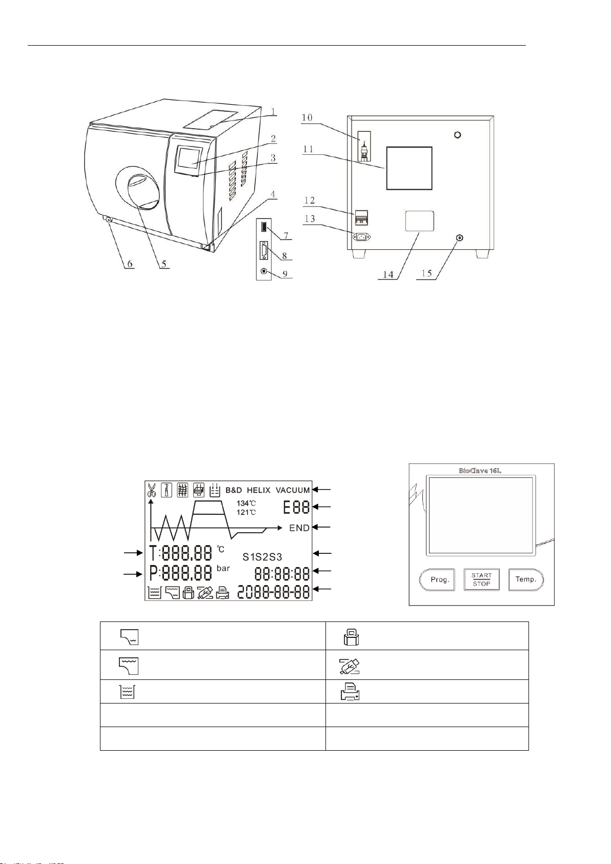
2.1 Sterilizer views
1. Distilled water tank
9. Printer (Optional)
2. Screen
10. Printer power.
3. Control Panel
11. Condenser vent
4. Main power switch
12. Safety valve
5. Drain connector (Distilled water tank)
13. Circuit breaker
6. Drain connector (Used water tank)
14. Power socket
7. Door handle
15. Rating plate
8. USB port
18. Used water tank vent
2.2 Control panel
Distilled water tank is required water.
Door locked
Distilled water tank is full
information output to USB port
Used water tank is full.
Printer is connected
Temp. Temperature button
Prog. Program button
START Start/Stop button
Notice: Button will be locked for the initial 10 seconds after powering up for system initialization.
Temperature
Pressure
Program
Alarm code
Process
Setting
Time
Date
Page 7
Instructions Manual
3
2.3 Technical specifications
Item
Parameter
Chamber
φ230 x 360 mm
Rated Voltage
220-240 VAC; 50 Hz
Circuit breaker
F16A/400V
Nominal power
1600VA
Sterilization temperature
121°C /134°C
Capacity of the distilled water tank
Approx 2.5 L (Water at level Max)
Approx 0.5 L (Water at level Min)
Operation temperature
5°C-40°C
Operation relative Humidity
Max. 80%, non condensing
Overall dimensions
440(W)x400(H)x620(D)
Net weight
39 kg
Max. Noise level
<70 dB
Atmospheric pressure
76 kPa - 106 kPa
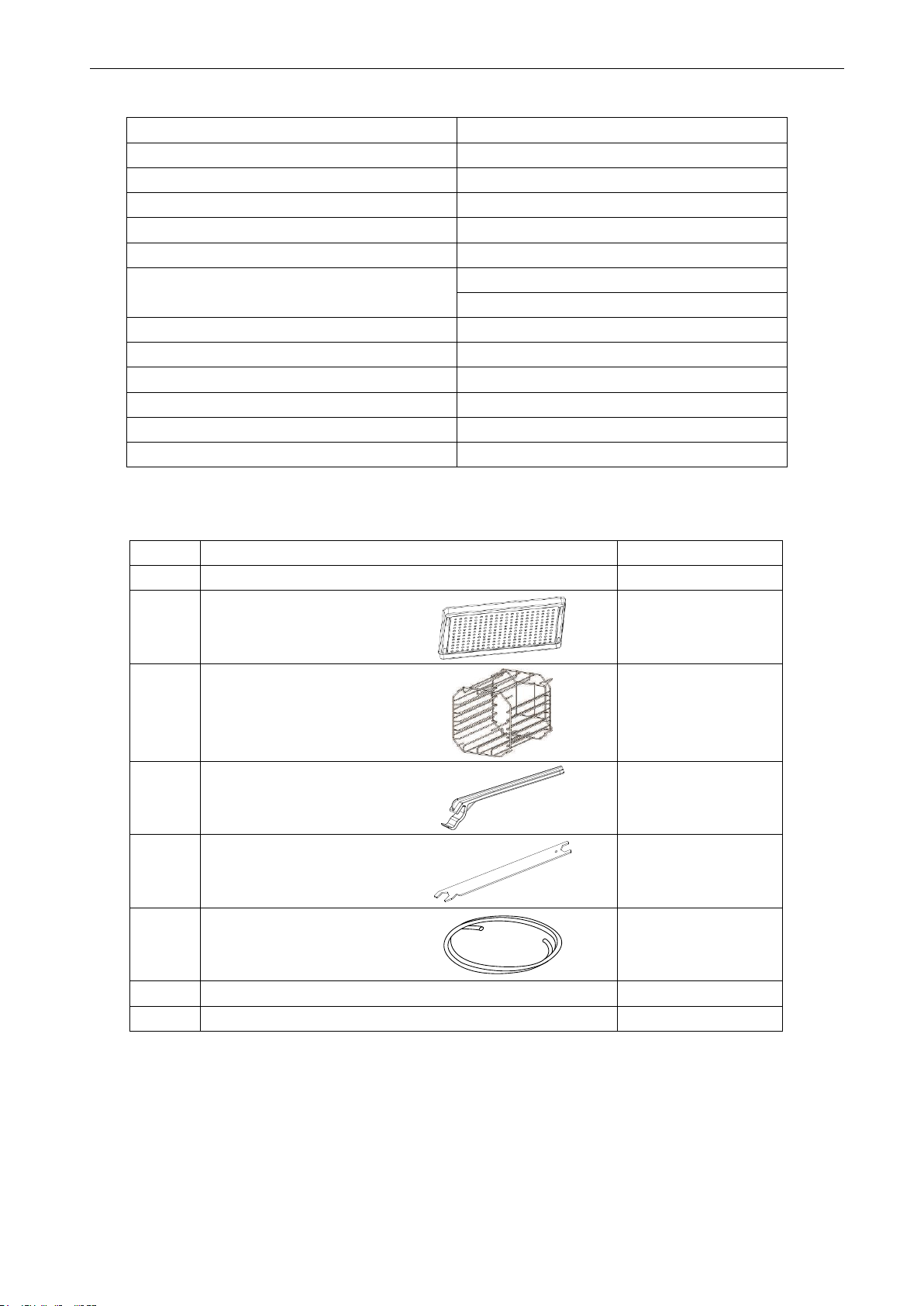
2.4 Packing content
No.
Accessory
Quantity
1
Steam sterilizer
1
2
Instrument tray
2
3
Instrument tray rack
1
4
Instrument tray handle
1
5
Door adjustment tool
1
6
Draining hose
2
7
Instructions manual
1 8 Door seal
1
Page 8

Instructions Manual
4
3. Installation
3.1 General conditions
Position the device on a plane surface with minimum capacity 60 kgs.
The sterilizer should be placed on a level worktable.
Improper water level in the chamber could cause a sterilizer malfunction.
Leave at least 10cm between the device rear part and the wall. The clearance required to open the door is 40cm.
Position the autoclave at such a height as to make it possible for the operator to check the whole sterilization chamber and
carry out the normal cleaning operations.
The room where the device is installed must be enough ventilated.
Do not install the device near washing basins, taps, etc. where it is likely to be splashed.
Do not lean on the door when it is opened.
Do not place trays , papers, fluid containers, etc. on the sterilizer.
3.2 Power supply connection
Check the label on back panel o sterilizer to verify voltage rating for the unit. Failure to connect the autoclave to an
appropriate power supply could result in damage to the unit, and electrical shock to personnel.
Plug power cord into a properly polarized and grounded receptacle rated. A dedicated circuit only used for the sterilizer is
recommended.
Never connect the device pin to reductions of any type.
4 Setup
Open the door and remove all of the inner contents for unpacking.
Connect the power cord to an outlet of the appropriate voltage.
Turn on the main power switch on the right side. After switching on, the machine turns on the LCD and shows the door
position, water level, working program, date, time and etc.
Note: The control panel will be locked for the initial 10 seconds after powering up for system initialization.
Notice: Before using the sterilizer or at any time the low water level icon blinks, fill the distilled water tank with
distilled water.
Page 9

Instructions Manual
5
4.1 Fill the distilled water tank
Ensure that the drain valve is closed.
Tap the button and open the water tank cover.
Use only high quality distilled water. (see Appendix 1)
4.2 Preparation of sterilization materials
For the most effective sterilization and to preserve the sample, please follow below:
*Clean instruments immediately after use.
*Treat the instruments by ultrasound cleaner.
*Residual chemicals left over after cleaning and disinfecting process may damage and corrode parts of the autoclave, always
rinse off the instruments using distilled water.
*Follow instrument manufacturer’s guidelines and recommendations for handing and cleaning instruments prior to
sterilization.
*Check the manufacturer’s instructions as to proper procedure for sterilizing of each item.
*Arrange the samples of different materials on different trays or with at least 3cm of space between them.
*Clean and dry instruments thoroughly before placing them into tray.
*Always insert a sterilization paper or cloth between the tray and sample to avoid direct contact.
*Arrange the containers (glasses, cups, test-tubes, etc) on one side or inverted position, avoiding possible water stagnation.
*Don’t stack the trays one above the other or put them in direct contact with the walls of the sterilization chamber.
*Always use the instrument tray handle.
*Wrap the samples one by one or, if more tools have to be set in the same bag, verify that these are made of the same
material.
*Don’t use metallic clips, pins or other, as this jeopardizes the maintenance of the autoclave.
*Don’t overload the trays over the stated limit (see appendix 2).
5. Operation
5.1 Select the program
Tap the Prog. button to select the program. And tap the Temp. button to select the temperature.
(Solid)
Unwrapped
Wrapped
Drying
Agar
Liquid
The water level should not exceed this port.
Page 10

Instructions Manual
6
5.2 Running the sterilization program.
After selecting program, the materials to be sterilized can now be placed on the
tray, placed inside the chamber by the tray handle.
After the instruments are loaded, you may close the door.
The icon will be lightened.
Caution: You must turn the door handle to the max. position,
otherwise the machine will alarm and prevent starting the cycle.
5.3 Start the sterilization program.
After the START button is taped, the stage and the status of the current cycle will appear on the display. The sterilizers will
perform the program automatically. (see appendix 2).
5.4 End of cycle
After cycle is completed, the printer will be activated and print out a report of the cycle (if the optional printer has been
connected) or save the report in the USB drive (optional).
Caution: Always use the tray handle to load or unload the tray into the autoclave.
Failure to do so can result in burning.
5.5 Manual abort of the program
It is possible to interrupt a started cycle prematurely. If you need to interrupt a cycle and remove the items urgently, you may
hold the START button for 3 seconds during the drying time to skip the dry cycle.
If you interrupt a cycle before it reaches the “Drying” step, the items inside the autoclave must be considered not be
sterilized.
If you need to interrupt a cycle after the holding time of the sterilization cycle and during the drying step, the items
inside the autoclave can be considered sterilized.
Caution: Depending on the status of the Cycle, steam can escape from the sterilization chamber when you open the
door.
Note: If the power shut off during the cycle is working, the screen will show a
special picture when power on again.
Total time or count
down until completion
Page 11

Instructions Manual
7
5.6 Record of the cycle
USB Flash memory (Optional)
A USB drive can be used as a method of storing a report of the cycle. To do so, insert the USB drive into the slot located on
the service door of the sterilizer.
The information will automatically output directly to the USB drive after the cycle has completed. The name of the file is
determined by the serial number of the machine and the cycle number.
For example:
The serial number is E00001. The cycle number is 0012.
The file name in the USB stick is E00001_00012E00.txt.
The first two numbers represent machine number.
The middle four numbers represent cycle number.
The last two numbers represent error code.
E.g. 00:no error;01: error E01
5.7 Printer (Optional)
5.7.1 Connect the printer cable.
5.7.2 Connect the printer power.
The printer (Optional) will print a report of the cycle that just ended. At the end
of each cycle the printer will print out a report of the cycle.
5.8 Report
In this menu you can read the report of the last 20 cycles stored in the internal
memory of the sterilizer.
Tap the button Prog. to the display of report. This will show the cycle No. Tap the
Temp. button to toggle between different cycles. To print or send the report to the
USB drive by tap the START button. When reading the reports, refer to the diagram
below:
When vising printed data records, refer to the diagram below:
Page 12

Instructions Manual
8
6. Advance setting
6.1 Enter the setting
6.1.1 Power on the machine while holding the START button for 3 seconds. This will enter
into the advanced setting mode.
6.1.2 Select the state ( state 1 to state 3 ) by taping the Prog. button. Tap the button START to
enter the setting.
================================
Program: Wrapped
Temperature: 134 C
Pressure: 204 kPa
Drying Time: 2.0 MIN
Holding Time: 04.0 MIN
------------------------------- Time Temp. Pressure
HH:MM:SS C kPa
Start 11:38:02 028.2 002.5
T1: 11:50:46 115.9 081.0
T2: 11:51:17 107.2 020.6
T3: 11:51:29 111.0 058.8
T4: 11:51:52 107.3 020.1
T5: 11:52:26 112.8 069.3
T6: 11:52:52 107.5 020.1
TS: 11:57:47 134.5 211.9
Max Temperature: 135.4
Min Temperature: 134.2
Max Pressure: 221.1
Min Pressure: 210.7
T7: 12:01:48 135.2 218.8
T8: 12:08:01 100.6 000.1
T9: 12:17:45 098.7 001.1
End 12:17:47 098.7 001.6
-------------------------------Cycle No.: 00022
Ster. Value: Success
Water quality: OFF, 000
Date: 20-05-2019
SN:A00001
Operator:
3AN00D 11100010V2.9.1.3
0000
==============================
Page 13

Instructions Manual
9
6.2 S1 State
If you select the S1. You may change the unit of the temperature and pressure, and adjust
time and date.
6.2.1 The first option is to select the unit of temperature. Tap Temp. button to select the unit.
The unit you selected will be lighted. Tap the Prog. button to the next item.
6.2.2 You may select the unit of pressure in the same manner.
6.2.3 Then tap Prog. button to the next item to adjust the time and date. After the last letter of the date or time is set, then
the data is permitted to be saved. If you want to finish the setting you shall tap START button. It will return to the
screen of selecting stages.
6.3 S2 State.
Note: The Serial No. and Cycle No. can not be set by the operator.
6.3.1 You may check the count of sterilization cycle. It can not be changed by operator.
6.3.2 The value of pressure is not zero if in a high altitude place. We can set the ambient pressure manually. Open the door,
select this item, press START button. The pressure will change to zero after set the pressure.
6.3.3 Language set.
6.4 S3 State
6.4.1 Adjust the length of the sterilization and drying time. Tap program Prog. button to select the program.
Tap temperature Temp. button to select the temperature of
program. Then tap START button to adjust the drying time and
holding time.
6.4.2 First to adjust the holding time.
Tap the Temp. button to adjust the data.
Tap the Prog. button to select the items.
6.4.3 Tap START to save.
6.4.4 Drying time is 0-60.
Holding time of 121 °C is 1-60.
Holding time of 134 °C is 1-20.
Note: The number will change quickly after you hold the Temp. button for 3 seconds.
Notice: The default sterilization parameters have been chosen to provide optimal sterilization result. We do not suggest
adjusting these parameters unless it is necessary.
Notice: Don’t set the value of S4. Please ask your dealer in case of you need it.
00
Chinese
01
English
02
German
03
Spanish
04
Polish
05
French
06
Hungary
07
Romanian
08
Dutch
09
Lithuanian
10
Latvian
11
Czech
12
Italian
13
Portuguese
14
Croatian
15
Russian
drying time
Language Setting
Ambient Pressure
holding time
SN
Counter
Page 14

Instructions Manual
10
Page 15

Instructions Manual
11
7.Maintenance
To assure proper operation and maximum autoclave life, carefully follow all recommendations for periodic maintenance.
One of the MOST important steps you can take to prevent problems with your sterilizer is to use ONLY distilled water.
Frequency
Number of cycles
Maintenance operation
Monthly
50
Clean the door seal
Clean the filter inside the chamber and in the clean
water tank
Clean the chamber the trays and the rack
Clean the external surface
Every 3 months
200
Clean the distilled water tank
Every year
800
Replace the door seal
7.1 Clean the distilled water tank
Disconnect the main cable.
Drain the tank completely using the drain tube and leave it connected into the connector in a
open position.
Clean the internal surface with a soft sponge and a small soft brush for the areas that are difficult
to reach using and a mild soap.
Remove the filter and clean it with a small soft brush and mild soap, rinse it with distilled water
and put it back in to the position.
7.2 Clean Chamber, door seal, trays and tray Rack.
Remove the trays and tray rack from the chamber.
Clean trays, rack and inside of chamber with mild soap.
Rinse the trays, rack and inside of chamber with a smooth cloth and distilled water.
Examine door seal for possible damage.
Clean door seal and mating surfaces with a damp cloth.
Note: Do not use bleaching agents or any abrasive materials / substances in
chamber. Failure to comply may result in damage to the chamber and/or other
components.
Caution: To prevent burns, let unit to cool before cleaning gaskets and
touch the surface.
7.3 Door adjustment
Under normal circumstances the chamber door does not require adjustments. However, if the seal
fails (resulting in steam leaking from the front of the chamber), you may use the spanner tool to
tighten the door seal.
Open the door.
Insert the spanner tool in the gap beneath the plastic cover; use the spanner to grip the adjusting
nut. Turn the nut counter clockwise as the figure below. This will tighten the sealing plate.
Turn the nut until the sealing plate is tight. If the door knob is too tight, you may also turn the nut
clockwise to loosen it.
Caution: Never adjust the chamber door while the door is closed.
Page 16

Instructions Manual
12
7.4 Replacement of the door seal
Open the chamber door. Remove the door seal ring carefully by hand.
Clean the door seal ring carefully with a smooth cloth with distilled water.
Moisten the new seal with distilled water.
Insert the new seal and Tap in sequence as follows:
1) Press in the top and bottom
of the door seal.
2) Press in the left and right
sides of the door seal.
3) Press the remaining
sections of the seal.
Caution: Please ensure the chamber and the door are cooled prior to replacing the seal ring.
7.5 The drain valve
1.Press the included hose on
the drain valve firmly.
2.Pull the drain valve
outward to drain the tank.
3. Push the drain valve back
after draining the tank.
Page 17

Instructions Manual
13
8.Error codes
Code
Description
Proposed solution
E1
Steam generator temperature sensor
error
Power off & run a new cycle
Contact your supplier if error persists.
E2
Inner temperature sensor error
Power off & run a new cycle
Contact your supplier if error persists.
E3
Temperature sensor of the chamber
wall error
Carefully ensure that the chamber wall is heated and
contact your supplier
E5
Fail to release the pressure
Power off & run a new cycle
Contact your supplier if error persists.
E6
Door lock problem during the cycle
Make sure you had closed the door properly.
check the door switch
E7
The pressure is too lower during
holding time.
Contact your supplier if error persists.
E8
The pressure is too high during
holding time.
Contact your supplier if error persists.
E9
Failure to hold temperature
Ensure the distilled tank isn't empty. Check the inner
temperature sensor. Check somewhere for leaking.
E11
Failure to preheat the steam
generator
Power off & run a new cycle
Contact your supplier if error persists.
E12
Failure to preheat the chamber
Power off & run a new cycle
Contact your supplier if error persists.
E16
The pressure doesn’t reach 0 in 5
minutes after drying period.
Contact your supplier if error persist
E20
Program manually interrupted
Holding the START button for 3 seconds.
E21
Failure to reach the holding time.
(sterilization time)
Check somewhere leaking inside the autoclave.
Contact your supplier if error persist
E24
It takes too long time to enter the next
status.
Check somewhere leaking.
Or contact your supplier if error persists.
E28
The pressure is overload.
Power off and contact your supplier if error persists.
E29
Power failure during working.
A notification message.
E34
The pressure is higher than 30kPa
during drying.
The solenoid valves are blocked.
Caution: You may cancel the voice of alarm by taping any button. And cancel the alarm by holding the START button for 3
seconds after you repair it.
Page 18

Instructions Manual
14
9. Transportation and storage
9.1 Switch off the sterilizer before transportation or storage.
9.2 Pull out the plug. Let the machine cool down.
9.3 Drain the distilled water tank and the used water tank.
Condition for transport and storage
Temperature: -20°C ~ +50°C
Relative humidity: ≤ 85%
Atmospheric pressure: 50kPa~ 106kPa.
10. Safety devices
1.Main fuses: Protection the instrument against possible failures of the heating resistor.
Action: Interruption of the electric power supply.
2.Thermal cutouts on the main transformer winding: protection against possible short circuit and main transformer primary
winding overheating
Action: Temporary interruption of winding.
3.Safety valve: Protection against possible sterilization chamber over-pressure.
Action: Release of the steam and restoration of the safety pressure.
4.Safety micro-switch for the door status: Comparison for the correct closing position of the door.
Action: Signal of the wrong position of the door
5.Thermostat on chamber heating resistors: Protection for possible over heating of the chamber heating resistors.
Action: Interruption of the power supply of the chamber resistors.
6.Thermostat on steam generator heating resistors: Protection for possible overheating of the steam generator heating
resistors.
Action: Interruption of the power supply of the steam generator resistors.
7.Door safety lock: Protection against accidental opening of the door.
Action: Impediment of the accidental opening if the door during the program.
8.Self-leveling hydraulic system: Hydraulic system for the natural pressure leveling in case of manual cycle interruption, alarm
or black-out.
Action: Automatic restoration of the atmospheric pressure inside chamber.
Page 19

Instructions Manual
15
Appendix 1
Water properties / Characteristics
Description
Feed water
Condensate
Evaporate residue
≤ 10mg/ I
≤ 1.0mg/kg
Silicium oxide sio2
≤ 1mg/ I
≤ 1.0mg/kg
Iron
≤ 0.2mg/ I
≤ 0.1mg/kg
Cadmiun
≤ 0.005mg/ I
≤ 0.05mg/kg
Lead
≤ 0.05mg/ I
≤ 0.1mg/kg
Rest of heavy metals
≤ 0.1mg/ I
≤ 0.1mg/kg
Chloride
≤ 2mg/ I
≤ 0.1mg/kg
Phosphates
≤ 0.5 mg/ I
≤ 0.1mg/kg
Conductivity
≤ 15μs /cm
≤ 3 μs /cm
PH Value
5 – 7.5
5-7
Appearance
Colorless, clean
Colorless, clean
Hardness
0.02 mmol/ I
0.02 mmol/ I
Page 20

Instructions Manual
16
Appendix 2
Diagrams of the sterilization programs
The time required for sterilizer to be ready for routine use after the power is switched is less than 5
minutes.
The max. Temperature of the 134°C sterilization cycle is 137°C
The max. Temperature of the 121°C sterilization cycle is 124°C
Programs
Temperature (°C)
Pressure (
psi)
Holding time
(min)
Total time (min)
Type
Max load (kg)
Max load per tray
(kg)
(Solid)
Unwrapped
134
30.5
4
17-27
Unwrapped solid material
4.00
1.20
121
16.0
20
27-37
Wrapped
134
30.5
4
22-32
Unwrapped solid material
3.50
1.10
121
16.0
20
32-42
Single-wrapped solid or hollow
material
3.50
1.10
Agar
121
16.0
25
47-57
Agar
1.00
0.30
Liquid
134
30.5
10
35-45
Liquid
1.00
0.30
121
16.0
30
47-57
Drying
― ― ―
1-60
―
―
―
Unwrapped
Wrapped
Drying
Liquid
AGAR
Page 21

Instructions Manual
17
Appendix 3
Wiring diagram
TP1: Steam generator temperature sensor
TP2: Inner temperature sensor 1
TP3: Temperature sensor of chamber wall
V1: Air release valve
V4: Water release valve
Chamber heater
Steam generator heater
Steam generator heater
Chamber heater
Thermal protector
Water pump
Fan
Printer Port
USB drive
Tank Min. Level
Public
Tank Max. Level
Used water tank
Printer power
Door close switch
TP3
TP2
TP1
Display screen
Door locking
power
Water quality
Label printer
Page 22

Instructions Manual
18
Appendix 4
Hydraulic diagram
V1: Air release valve
V4: Water release valve
Distilled water tank
Safety valve
Chamber
Test Port
Condenser
Pressure sensor
 Loading...