

Page 1

FoodTech
Source™
PORTABLE FOOD ANALYZER
with AutoBIAS™
USER'S MANUAL
Version 2.1
COLE PARMER INSTRUMENT CO.
625 East Bunker Court
Vernon Hills, IL USA 60061
Phone: 847-549-7600
Fax: 847-247-2983
E-mail: info@coleparmer.com
Website: http:/www.coleparmer.com
© Zeltex, Inc. 2001
This manual provides you with all the information needed to operate the
Cole-Parmer FOODTECH™
Page 2

2
TABLE OF CONTENTS
WARNING: 4
ABOUT THE FOODTECH™ 5
FEATURES OF THE FOODTECH™ 5
UNPACKING THE FOODTECH™ 5
PREPARATION 7
ELECTRICAL REQUIREMENTS 7
OPTIONAL PRINTER 7
PRINTER PAPER INSTALLATION FOR OPTIONAL PRINTER 7
SAMPLE CUP 8
CLAM-SHELL CUP 9
VARIABLE PATHLENGTH SAMPLE CUP 12
KEYPAD DESCRIPTION 13
TURNING THE FOODTECH™ ON FOR THE FIRST TIME 14
AUTOMATIC BIAS INITIALIZATION AND STANDARDIZATION 15
ANALYZED SAMPLE FORM 17
SELECT PRODUCT 18
MENU SELECTIONS 18
MEASURING A SAMPLE 19
ADJUSTING THE CALIBRATION 21
ADJUSTING THE BIAS 22
AUTOBIAS 22
ADJUSTING THE TIME 23
ADJUSTING THE DATE 23
ADJUSTING THE NUMBER OF READ CYCLES 23
STORE SAMPLES 24
DATA LINK 24
PRINTING 25
PAPER FEED 25
RESET ID # 26
WARNINGS AND ERROR CODES 27
Page 3

3
GENERAL SPECIFICATIONS 31
A NOTE ON THE TEXT
Throughout this manual, keystrokes are represented in bold type; references to
messages on the computer screen or the FOODTECH™ display screen are in
“quotations.”
GLOSSARY 32
APPENDIX I 34
COMBINATION LOCK 34
INDEX 35
Page 4

4
WARNING:
THE FOODTECH™ PORTABLE NEAR-IR
ANALYZERS ARE NOT EXPLOSION
PROOF: REASONABLE CARE MUST BE
USED IN HANDLING THESE
INSTRUMENTS.
THE FOODTECH™ IS SUPPLIED WITH A
SPECIAL STATIC-FREE CLEANING
BRUSH. FAILURE TO USE THIS BRUSH
BETWEEN SAMPLES MAY CAUSE
BAD READINGS.
Page 5

5
ABOUT THE FOODTECH™
FEATURES OF THE FOODTECH™
Easy sampling: no grinding, no preparation
Analyzes whole grain products such as wheat (spring and winter), barley,
soybean and corn
Analysis in 60 seconds or less
Stores calibrations for 3 constituents each of up to 10 products
Accurate up to 95% of moisture, protein, oil, etc.
Able to analyze samples at temperatures from -20ºC to +50ºC.
Direct readout in percentage form for both AS-IS and CM
Totally solid state optics (no moving parts)
Automatic Bias Initialization and Standardization
UNPACKING THE FOODTECH™
Check that all items 1 through 6 are in the box. If any items are missing,
please contact Cole-Parmer immediately.
1. FOODTECH™ Portable Food Analyzer (PFA)
2. User's Manual
3. Quick Start Manual
4. AA Batteries
5. 16 mm Sample Cups
6. Static Brush
Optional:
1. Carrying Case
2. Software Disk and Calibration Manual
3. A/C Adapter
4. RS232 Cable
5. Printer
6. Printer Paper
7. 25 mm Sample Cup (corn, soybean)
8. Variable Pathlength Sample Cup 5 mm-16 mm (small grains)
9. AutoBIAS perma-sample
The optional carrying case has the combination set at the factory to open at
000. You may leave it at this setting or you can set your own combination.
(See Appendix 1 in this manual for instructions on how to set your own
combination.)
Page 6

6
APPEARANCE AND PART NAMES
Page 7

7
PREPARATION
ELECTRICAL REQUIREMENTS
After you have opened the carton, take a moment to consider where to
place the FOODTECH™ The instrument has been designed to work
flawlessly in the manufacturing environment, but please take into account
the following requirements before setting up the instrument.
The FOODTECH™ operates from six AA cells or 9v DC from an A/C
adapter. For the best operation and the most reliable analysis, the
FOODTECH™ should have a clean, independent electrical line with the A/C
adapter. Depending on the A/C voltage at the customer’s site, the
appropriate adapter (nominal 115 or 230 VAC) is shipped with the
instrument. Connect the A/C adapter cable to the jack closest to the top on
the right-hand side of the instrument. Also, insert six 1.5v AA size alkaline
batteries into the battery compartment located on the rear of the main body.
Be sure the batteries are oriented as indicated in the compartment.
OPTIONAL PRINTER
The optional printer can be attached directly to the FOODTECH™
PRINTER PAPER INSTALLATION FOR OPTIONAL PRINTER
1. Remove the clear plastic cover from the printer.
2. Cut the end of the roll at an angle to form a point in the center.
3. Feed the paper into the slit inside the Paper Roll Compartment and press
the PAPER FEED key.
Page 8
8
SAMPLE CUP
Molded 16mm Cup
Stock #2670
24mm Cup
Stock #A-572
Variable Path-Length Cup
Stock #2672
Clam-Shell Cup
Stock #A0636
The FOODTECH™ is shipped with 2 standard 16mm (approx. 3/4”) sample
cups to be used with wheat and barley. A 24mm (approx. 1”) cup and a
variable pathlength cup are also available.
Do not place objects on the sample cup. It should not be placed in direct heat
or cleaned with harsh chemicals such as scouring powder.
Page 9
9
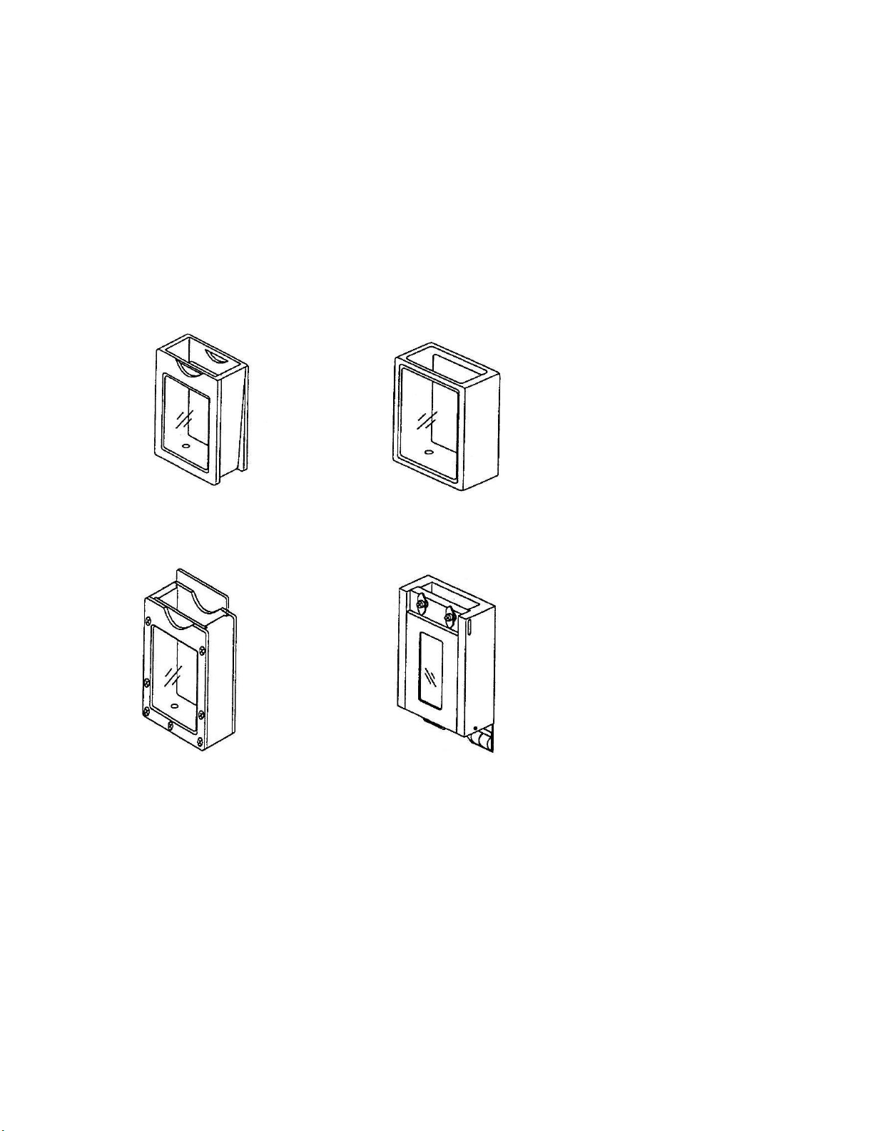
CLAM-SHELL CUP
The A0636 Clam-shell Cup allows the analysis of pastes and slurries in clear
“whirl-pak”–type bags. The Clam-shell Cup includes an internal A0633
Thermistor Module (a), contact strips (b), windows in the body and door (c), and
an assortment of different thickness windows (d).
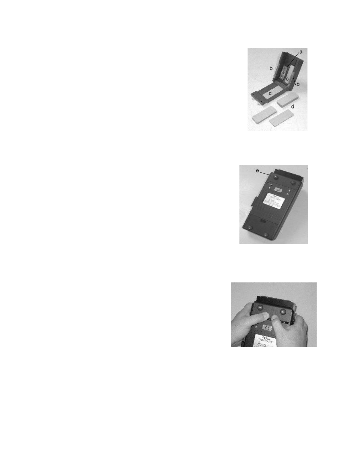
Because the Clam-shell cup has its own thermistor, the thermistor probe in the
instrument must be removed. First, locate the thermistor cover (e). It is the
smaller of the two covers on the bottom of the instrument.
Remove the thermistor cover by pressing down with the thumbs, and sliding
the cover upward.
Page 10
10
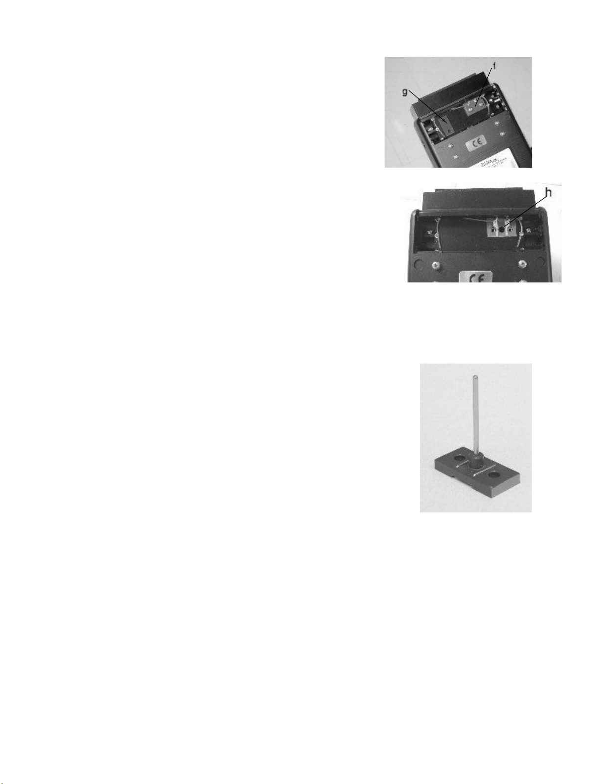
Inside the thermistor recess, you’ll note the Thermistor Probe assembly
(f) (held in with two 6-32 screws), and the Black Spacer (g).
Remove the Black Spacer (held in with tape), and the Thermistor Probe,
exposing the Contact Board (h). Note the red and green wires which are
connected to the Contact board.
This is a close-up of the A0516 Thermistor Probe. Note that one end of the
probe is painted green. If the Thermistor Probe is re-installed later, the green end
should be closest to the green wire on the contact board.
Page 11
11
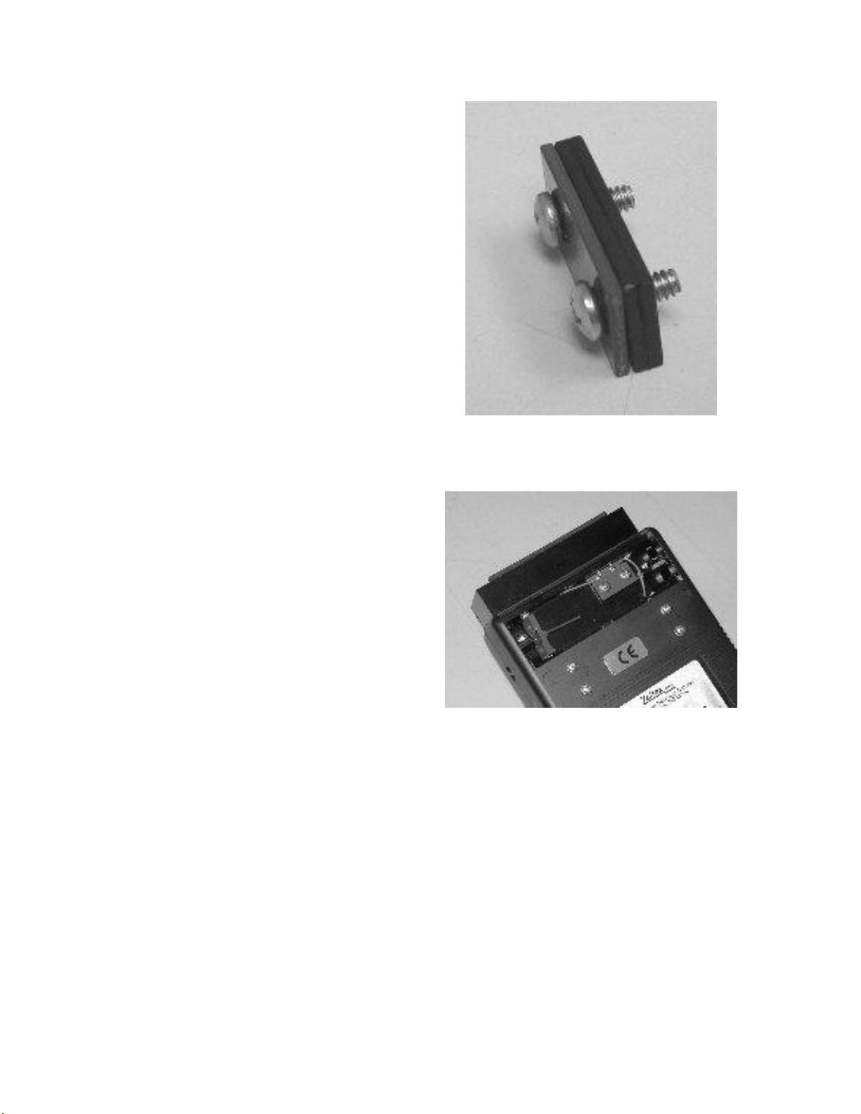
To plug the holes in the sample chamber, make a Spacer
Assembly from the Gray Stop Plate, the Black Spacer,
and two 6-32 screws.
Install the Spacer Assembly as shown. Storing the
Thermistor Probe as shown will keep it from getting
lost. Re-install the Thermistor Cover, and you’re
done. To convert back, reverse the procedure.
Page 12

12
VARIABLE PATHLENGTH SAMPLE CUP
The Variable Pathlength Sample Cups uses windows of different thicknesses slide in and out of slots
Page 13

13
KEYPAD DESCRIPTION
The Cole-Parmer keypad is designed to be easy to use.
ENTER This key is used after a selection has been made on the menu.
PRODUCT This key is used to make a product selection.
SELECT This key is used before entering any adjustable programming
ESC within the instrument. It can also be used to cancel a current
entry in the instrument.
MEASURE This key is used to make measurements.
CM * This key toggles the displayed result between Protein on a
AS-IS Constant Moisture basis or on an AS-IS basis.
▲ ▼ These arrow keys cycle through menu selections.
Page 14

14
TURNING THE FOODTECH™ ON FOR THE FIRST TIME
1) If you are using batteries, simply turn on the FOODTECH™ by the
switch on
the right side and go to step 3).
If you are running the FOODTECH™ on batteries, please make sure the
instrument is shut off when not in use. The batteries will last much longer if
the instrument is off when sitting idle.
2) Plug the adapter into the right side of the FOODTECH™ Turn on the
power
switch. The FOODTECH™ begins a test sequence: “TEST EPROM, TEST
RAM, TEST IREDS, TEST ADC, TEST THERM.” When “Measure Standard”
is displayed, the test sequence has been completed.
3) Run the AutoBIAS sample (if option is installed), following the
directions on page 15.
4) Measure ten samples of the product that the instrument has been
calibrated for. (These samples must have already been analyzed by your lab.)
Write the analysis in the chart provided on page 17 and fax the form or call
Cole-Parmer at:
FAX: 1-847-247-2983
PHONE in the USA: 1-888-409-3663
outside the USA: 1- 847-549-7600
Cole-Parmer will give you any necessary adjustments.
Page 15

15
AUTOMATIC BIAS INITIALIZATION AND STANDARDIZATION
You can elect to run an AutoBIAS at any time, in
addition to the daily AutoBIAS prompt. Make sure
you are in the product whose bias you want to
adjust. Press SELECT ESC. Use the arrow keys
(▲▼) to scroll through the menu until “Auto Bias”
appears on the screen. Press ENTER.
(Optional)
When you turn the instrument on each day, it will require you to run
an AutoBIAS sample in each product you use.* The AutoBIAS feature uses
the latest NIR technology to prevent the FOODTECH™ from drifting out of
calibration.
The instrument will prompt, “BIAS ADJUST [product].” Press
ENTER. The instrument will read the empty chamber, then prompt, “Insert
Sample.” Do so; then press MEASURE. The screen will prompt, “Remove &
Turn.” DO NOT TURN THE CUP: the perma-sample can only be inserted
one way. Just press MEASURE. Remove and replace the sample when
prompted; press MEASURE. Remove the sample when prompted and press
MEASURE. The instrument will read the empty chamber again.
The instrument will decide how many times it needs to read the
sample. At this point, it may prompt, “READ AGAIN.” If it does so, DO NOT
INSERT THE SAMPLE. Press MEASURE. After it reads the empty
chamber again, it will tell you to “Insert Sample.” Repeat the process. It may
ask you to read the sample several times. Do not be alarmed. Simply follow
the directions until the screen gives the constituent name and a value. This
value is the amount of the bias adjustment for that constituent: Write it on
the attached Daily AutoBIAS Adjustment Record. Press ENTER. The
instrument will automatically adjust the bias by the amount shown. The
second constituent bias amount will appear. Record it and press ENTER
again. Continue until all the constituents have been adjusted.
You are now ready to begin reading samples in the adjusted product!
* If you are unable to run the AutoBIAS sample for some reason, you can escape the daily
AutoBIAS prompt by pressing the arrow keys in the following order: up, down, up (▲▼▲). Do
not make a habit of ignoring the AutoBIAS prompt. If you have lost the AutoBIAS sample,
contact Cole-Parmer for a replacement.
Page 16

16
PRODUCT # AutoBIAS AMOUNT FOR
and NAME
DATE
CON 1
CON 2
CON 3
CON 4
___/___/___
___/___/___
___/___/___
___/___/___
___/___/___
___/___/___
___/___/___
___/___/___
___/___/___
___/___/___
___/___/___
___/___/___
___/___/___
___/___/___
___/___/___
___/___/___
___/___/___
___/___/___
DAILY AutoBIAS™ ADJUSTMENT RECORD
Keep a blank copy of this sheet.
Page 17

17
ANALYZED SAMPLE FORM
Sample
Number
Analyzed
Sample
Lab
Protein
AS-IS
FOODTECH
™ Protein
AS-IS
Analyzed
Sample
Lab
Moisture
FOODTECH
™
Moisture
Analyzed
Sample
Lab
_________
FOODTECH
™
_________
1
2
3
4
5
6
7
8
9
10
SEND TO: Cole-Parmer Instrument Co., USA, FAX NO.: 1-847-247-2983
FROM: Company name, Country ___________________________________________
CONTACT PERSON: (please print) _________________________________________
PHONE: Country code ________ Number __________________________________
FAX: _____________________________________________________________________
Enter in the Analyzed Sample columns ten (10) samples that have been
analyzed by your lab. In the corresponding columns, enter the FOODTECH™
readings for the same samples. Fax to Cole-Parmer for advice concerning any
needed adjustments.
Page 18

18
SELECT PRODUCT
1. Press Product.
Press the arrow keys (▲ ▼) to cycle through the products. The different products
will be listed. (The Portable Food Analyzer is able to store ten products,
numbered as 0-9.)
2. Press ENTER when the product to be tested is on the display. Only one
product can be selected at a time.
MENU SELECTIONS
1. Turn on analyzer.
2. After test sequence is complete, press Select Esc. “Enter Bias” will
appear on the FOODTECH™ screen.
3. Press the arrow keys to cycle through the selections:
Enter Bias - adjust the calibration
Data Link - to communicate with the computer
Store Sample - saves samples in internal memory to be downloaded
to the computer
Paper Feed - for the optional printer
Reset ID # - resets the sample ID number to 1
Auto Bias - maintains calibration accuracy
Set Date
Set Time
Printing - for the optional printer
Set Readings - number of times that each sample is read—Cole-
Parmer recommends 4
4. Press ENTER to select the option on the screen.
Page 19

19
MEASURING A SAMPLE
1. Turn power switch ON. “FOODTECH™ PFA” will be displayed. The display
will show a version number and then will begin a test sequence. “Measure
Standard” will be displayed when the test sequence has been completed.
2. Select the product according to the sample type to be measured. (See “Select
A Product”)
3. Fill the sample cup with sample and tap the cup twice on a hard surface.
4. Make sure there is nothing in the sample chamber and close the lid over the
sample chamber.
5. Press MEASURE. The display will show “Reading . . .,” then “Insert
Sample.” This indicates that the instrument has been standardized. The
PFA must be standardized prior to making any measurement.
6. Lift the lid from the sample chamber and place the cup containing the sample
in the chamber.
7. Replace the lid over the sample in the chamber. This shield must always be
used when measuring a sample or a standard; otherwise, the results will be
incorrect.
8. Press MEASURE. The display will show “Reading . . .,” then “Remove &
Turn.” Remove the sample, rotate the sample cup 180 degrees and replace it
in the FOODTECH™ PFA. Close the lid.
9. Press MEASURE. The display will show “Reading . . .,” then “Remove &
Reload.” Remove the sample cup, pour out the sample, and refill the cup with
the same sample.
10. Tap the sample cup twice on a hard surface, replace it in the sample
chamber, and close the lid.
11. Press MEASURE. The display will show “Reading . . .,” then “Remove &
Turn.” Remove the sample cup, rotate the cup 180 degrees, and replace it in
the FOODTECH™ PFA. Close the lid.
12. Press MEASURE. The display will show “Reading . . .,” then “Remove &
Press M.” Remove the sample.
Page 20

20
13. Close the lid over the empty chamber and press MEASURE.
14. The results will be displayed. Use the down arrow key to list the results of
each constituent.
15. To measure another sample of the same product, press SELECT ESC to
clear the results. The instrument will return to “Measure Standard.” Repeat
steps 3-14.
Remember:
At any prompt where you have to either enter a sample or remove a sample and
press MEASURE, the instrument will allow you only 50 seconds to do so. If
after the elapse of 50 seconds you have not completed the task required, the
FOODTECH™ will flash “Time Out!” and automatically return to “Measure
Standard.” This feature is designed to prevent readings from becoming “stale.”
Page 21

21
ADJUSTING THE CALIBRATION
Sample Number
FOODTECH™ Protein
As-Is
Lab Protein As-Is
1
10.0
10.2
2
11.1
11.3
3
12.3
12.6
4
10.4
10.5
5
9.1
9.3
6
10.8
11.0
7
12.0
12.1
8
11.2
11.4
9
8.8
9.0
10
9.6
9.8
Column Average =
10.5
10.7
The FOODTECH™ has been carefully calibrated at the factory or at your
location; however, sometimes it is necessary to adjust the calibration for a bias.
A bias adjustment fine tunes the FOODTECH™ by shifting all readings up or
down by the same amount.
A. Obtain ten laboratory-analyzed samples.
B. Measure the samples in the FOODTECH™
C. Compare the instrument readings with the laboratory analysis or fax the
data to Cole-Parmer at 847-247-2983 and Cole-Parmer will provide any
necessary adjustments. See the following example of data requiring a
bias adjustment.
Example: Determine the average FOODTECH™ value and the average
laboratory value. The difference between the two will be the bias adjustment.
In the above example, the FOODTECH™ is reading Protein As-Is 0.2% too low
(determined by the difference between the averages of the two columns). The
bias adjustment will be +0.2 for Protein As-Is.
Page 22

22
ADJUSTING THE BIAS
1. Turn on the instrument.
2. Make sure you are in the product that requires the bias adjustment. (See
“Select a Product”)
3. When “Measure Standard” is displayed, press SELECT ESC.
4. “Enter Bias” will appear on the display. Press ENTER.
5. The product and constituent appear:
Example: PØ WHT C1 PRO
6. Use the arrow keys to cycle through the constituents. Press ENTER after the
constituent for which you are adjusting the bias appears.
7. “Bias: Ø.Ø” will appear. Use the arrow keys to cycle through the numbers.
Press ENTER when the correct bias is displayed. Make sure the decimal
point is in the right place. “Complete” will appear.
8. If for any reason you must abort, press SELECT ESC to abort the bias
adjustment.
AUTOBIAS
1. To run the optional AutoBIAS, select “Auto Bias” on the FOODTECH™ menu
and press ENTER. (See also the AutoBIAS instructions on page 15.)
2. Follow the instructions on the screen, using the AutoBIAS perma-sample
provided by Cole-Parmer or your own sealed AutoBIAS sample. (See the
FOODTECH™ Calibration Manual for instructions on creating an AutoBIAS
sample and setting the instrument to read a different AutoBIAS sample.)
3. Run the sample as many times as the instrument requests.
4. Record the date and the amount of the bias adjustment on a copy of the
AutoBIAS Adjustment Record on page 16.
Page 23

23
ADJUSTING THE TIME
1. Turn PFA on.
2. At the “Measure Standard” prompt, press SELECT ESC.
3. When “Enter Bias” is displayed, use the arrow keys ((▲ ▼) to cycle through
the menu until “Set Time” appears.
4. Press ENTER.
The up arrow key (▲) cycles through the hours.
The down arrow key (▼) cycles through the minutes.
The CM* AS-IS key zeroes the seconds.
5. Press ENTER after the time has been adjusted.
ADJUSTING THE DATE
1. Turn on the PFA.
2. After the test sequence is completed, “Measure Standard” is displayed.
3. Press SELECT ESC. “Enter Bias” will appear.
4. Use the arrow keys to cycle through the menu to find “Set Date.” Press
ENTER.
The up arrow key (▲) cycles through the months.
The down arrow key (▼) cycles through the days.
The CM*/AS-IS key cycles through the years.
5. Press ENTER after the date has been adjusted.
ADJUSTING THE NUMBER OF READ CYCLES
The FOODTECH™ is designed to allow you to use between 1 and 9
repetitions to get the maximum accuracy needed for your samples in a minimum
of time.
Cole-Parmer recommends using four (4) repetitions.
1. Turn on PFA.
Page 24

24
2. At the “Measure Standard” prompt, press SELECT ESC.
3. When “Enter Bias” is displayed, use the arrow keys (▲ ▼) to cycle through
the menu to find “Set Readings.” Press ENTER.
4. “# Reads: 4” is displayed. Use the arrow keys to cycle through the numbers.
Press ENTER at the number of your choice.
STORE SAMPLES
(Optional)
The PFA is able to store the OD’s and sample ID’s for up to 25 samples in
battery-backed RAM. The samples are stored in the same memory as the K
values. This means that the sample readings are preserved even when the
FOODTECH™ is turned off. The samples that are saved in the FOODTECH™'s
memory can be downloaded to a PC.
To save the last sample that was read:
1. Press SELECT ESC. “Enter Bias” will be displayed.
2. Use the arrow keys ((▲ ▼) to cycle through the menu until “Store Samples”
appears. Press ENTER.
3. “Saved #______“ indicates the number (1-25) of the saved sample in the
FOODTECH™’s memory.
After saving 25 samples, the instrument will wrap around and begin to
save again in position 1. This will overwrite the previous sample(s).
The samples can be downloaded to the PC using the optional software by
connecting the FOODTECH™ to the computer with an RS232 cable and
selecting “Download Saved Samples” from the Utility Menu of the calibration
program. See “Download Saved Samples” in the Calibration Manual.
DATA LINK
The FOODTECH™ must be in Data Link mode for it to communicate with
the PC. The FOODTECH™ is connected to the PC with an RS232 cable.
1. Turn on PFA.
Page 25

25
2. At the “Measure Standard” prompt, press SELECT ESC.
3. When “Enter Bias” is displayed, use the arrow keys ((▲ ▼) to cycle through
the selections to find “Data Link.”
4. Press ENTER. “DATA LINK” will be displayed in capital letters.
PRINTING
This selection is used with the optional printer.
To enable the printer:
1. Turn on the PFA.
2. At the “Measure Standard” prompt, press SELECT ESC.
3. “Enter Bias” will appear. Use the arrow keys (▲ ▼) to cycle through the
menu to find “Printing.” Press ENTER.
4. “PRN ENABLED” will be displayed. Press ENTER.
NOTE: Each time the FOODTECH™ is turned on, the printer must be enabled.
To disable the printer:
1. Turn on the PFA.
2. At the “Measure Standard” prompt, press SELECT ESC.
3. “Enter Bias” will appear. Use the arrow keys (▲ ▼) to cycle through the
menu to find “Printing.” Press ENTER.
4. “PRN DISABLED” will be displayed. Press ENTER.
PAPER FEED
This selection is used with the optional printer. The printer must be enabled
(See above). To advance the paper on the optional printer:
Page 26

26
1. Press SELECT ESC. “Enter Bias” will appear.
2. Use the arrow keys to cycle through the menu until “Paper Feed” is
displayed.
3. Press ENTER. The paper will advance one line each time ENTER is
pressed.
4. Press SELECT ESC to return to “Measure Standard.”
RESET ID #
This selection is used to reset the automatic sampling number to #1.
1. Turn on the PFA. Wait for “Measure Standard” to be displayed.
2. Press SELECT ESC. “Enter Bias” will appear on the display.
3. Use the arrow keys to cycle through the menu until “Reset ID #” appears.
Press ENTER.
4. “ID # Reset” will be displayed. The next sample run will be labeled sample
#1.
Page 27

27
WARNINGS AND ERROR CODES
Error: TOO DARK
Error: TOO LITE
****** WARNING ******
Error
AMB. TEMP TOO LOW
********************
The FOODTECH™ has a number of warnings and error codes built into it.
Some are overridden automatically on the analyzer; others require you to start
the reading again.
The range for the warnings can be set by using the Instrument Edit Utility
program on the Calibration Software.
1) This error occurs if the energy reaching the detector is less than the
acceptable level.
2) This will be displayed if the detector is in saturation. This normally is
caused by not placing the light shield on correctly while the instrument is
reading a sample or measuring the standard.
3) The FOODTECH™ was set up with a temperature check for itself. If the
instrument temperature is too cold, a warning, “AMB. TEMP TOO LOW” will
appear on the display. This can be overridden by pressing ENTER.
Page 28

28
****** WARNING ******
Error
AMB. TEMP TOO HIGH
*********************
****** WARNING ******
Error
SMP. TEMP TOO LOW
*********************
****** WARNING ******
Error
SMP. TEMP TOO HIGH
*********************
****** WARNING ******
* BAD CURVE *
********************
4) This indicates that the instrument is above the recommended
temperature range.
5) The FOODTECH™ was also set up with a temperature check for the
sample. If the sample temperature is too cold, a warning, “SMP. TEMP LOW,”
will appear on the screen. This can be overridden by pressing ENTER.
6) This indicates that the sample temperature is above the recommended
temperature range.
7) This will be displayed only if A, B, and C have been activated using the
Instrument Edit Utility program in the Calibration Software.
Page 29

29
Note: When entering Curve Checking on the Constituent Menu you should
****** WARNING ******
Error
HIGH VAR
***********************
****** ERROR ******
VALUE TOO LOW
**********************
always look at the curve on a typical sample on the computer. On the
bottom of the computer screen the filter numbers are displayed. You
should choose A as the highest peak of the sample, B as the second
highest peak on the sample, and C as the low point of the sample. This
allows you to verify that the curve is a reasonable shape for the curve you
calibrated for.
8) This is displayed if the variance among the four readings is more than
normal variance in the sample. This tells you that the repeatability within the
sample is not as reasonable as we would expect. This could be caused by light
leaks, an improperly aligned sample, or just variations in the samples.
9) This occurs when the reading for a particular constituent is outside the
range that was set up on the range of data on the Instrument Edit Utility
program.
10) At any prompt where you have to either enter a sample or remove a
sample and press MEASURE, the instrument will allow you only 50 seconds to
do so. If after the elapse of 50 seconds you have not completed the task required,
the FOODTECH™ will flash “Time Out!” and return to “Measure Standard.”
This feature is designed to not allow readings to become “stale.”
Page 30

30
****** ******
NO CONS NAME
**********************
****** ******
LOW BATTERIES
**********************
11) This is displayed after a sample reading to warn the user that the product
selected to run the sample does not have constituents named for that product.
12) This is displayed when the batteries need to be replaced.
Page 31

31
GENERAL SPECIFICATIONS
Carrying case
AutoBIAS perma-sample
Calibration software
Calibration manual
RS232 cable
AC adapter
Variable pathlength sample cup
24mm sample cup
Printer
Printer paper
1. MEASUREMENT
Measuring Principle: Near-Infrared Transmittance based on technology from the United
States Department of Agriculture
2. PRINTER OUTPUT (optional)
Product and Constituent name and analysis with time, date, and identification number
(manual or automatic)
3. DISPLAY
Product and Constituent name and analysis
4. POWER SOURCE
Six AA 1.5V alkaline batteries
9V A/C adapter (included)
5. DIMENSIONS
Main Body - 4.7 x 13.5 x 2.2 inches
6. WEIGHT
3 lbs
7. ACCESSORIES
Part Number
2 sample cups
1 Static Brush
6 AA alkaline batteries ZXP 103
1 User's Manual ZXP 111
1 Quick Start Manual
8. OPTICAL MEASUREMENT TECHNIQUE TRANSMITTANCE OF NEAR-INFRARED
USING: 14 wavelengths covering the range from 893 nanometers to 1045 nanometers
9. OPTIONS:
Page 32

32
GLOSSARY
application - the type of product the user is analyzing for a certain
constituent(s)
AutoBIAS - Automatic Bias Initialization and Standardization. Maintains the
accuracy of the calibration by daily adjustment.
bias - the average overall shift of the regression curve from the ideal laboratory
regression curve
constants - numbers that relate to the influence of each wavelength use in the
statistical calibration of the customers product
constituent - organic compound that is found in the sample being tested
diffuse transmittance - light energy is transmitted and distributed evenly
through the sample being tested
diodes - near-infrared red light sources
IR - abbreviation of infrared
K’s or K values - same as constants
lab analysis - the chemical or physical analysis of constituent(s) in a product
light absorption - the amount of light energy absorbed by various constituents
in the product being measured
linear regression - a graphical representation of a statistical analysis of the
relationship between two or more measured variables
nanometer or nm - one billionth of a meter
near-infrared - the range of light energy near the visible spectrum
near-IR - See near-infrared
OD - optical data expressed in terms of voltage values for each wavelength used
in a Cole-Parmer analyzer
Page 33

33
regression - the statistical liner, quadrant, or cubic means of comparing two or
more variables (ex: OD versus percentage of moisture)
sample - a measured amount of product to be tested
sensor - a device used in Cole-Parmer analyzers that converts light energy to
electrical signals for processing optical data
spectrum - the range of OD energy measured in wavelength increments
transmittance - the ease with which light or other forms of energy can pass
through a sample being tested
wavelengths - specific band widths of light energy, usually expressed in
nanometers in near-infrared instrumentation
HRS - Hard Red Spring Wheat
HRW - Hard Red Winter Wheat
SWW - Soft White Wheat
SRW - Soft Red Winter Wheat
BLY - Barley
CRN - Corn
SOY - Soybean
SML - Soymeal
Page 34

34
APPENDIX I
COMBINATION LOCK
Your combination lock is set at the factory to open at 000. You may leave
it at this setting or you can set your own secret combination in the following
manner:
1. Open the case. At the back of the lock you will see the change lever extending
from the body of the lock.
2. Move the change lever toward the dials of the combination lock and down.
3. Now turn the dials to your own secret number and write it down in a safe
place.
4. Without disturbing the setting of the dials, move the change lever back to its
original (normal) position. Make sure you have done this before closing the
case and using the lock.
Your case will now open only at your secret combination. If you want to
change the combination again, simply repeat these steps.
Page 35

35
INDEX
A/C adapter 7, 31
absorption 32
AutoBIAS 1, 5, 14, 15, 16, 22, 32
BAD CURVE 28
Batteries 5
bias 21, 22, 32
Bias 18, 22, 23, 24, 25
BIAS 22
bias adjustment 21, 22
BLY 33
BRUSH 4
calibration 18, 21, 24, 32
Calibration Software 27, 28
combination 5, 34
constituent 20, 22, 29, 32
CRN 33
curve 29, 32
Curve 29
CURVE 28
DARK 27
DATA LINK 24, 25
DATE 23
disable 25
ELECTRICAL REQUIREMENTS 7
enable 25
ERROR 27, 29
HRS 33
HRW 33
Instrument Edit Utility 27, 28, 29
KEYPAD 13
lab 14, 17, 32
light shield 27
LITE 27
main body 7
Measure Standard 14, 19, 20, 22, 23, 24, 25, 29
PATHLENGTH 12
printer 7, 18, 25
PRN DISABLED 25
PRN ENABLED 25
PRODUCT 13, 18
range 27, 28, 29, 31, 32, 33
READ CYCLES 23
regression 32, 33
repetitions 18, 23
RS232 cable 24
sample 5
Sample Cup 5
SML 33
SOY 33
SRW 33
standard 8, 19, 27
Standard 14, 19, 20, 22, 23, 24, 25, 29
SWW 33
temperature 27, 28
TIME 14, 23
Time Out! 20, 29
Transmittance 31
United States Department of Agriculture 31
variance 29
WARNING 4, 27, 28, 29
Page 36

36
Addendum
CM DISPLAY
When displaying measurement results, the instrument displays the AS-IS
calculation first by default. Pressing the CM/AS-IS Button will toggle back and
forth between CM and AS-IS.
If you should wish to display the CM results first, simply press the CM/AS-IS
button while the display says "Measure Standard". When pressed, the display
will say "CM DEFAULT". Any readings taken afterwards will show the CM
results first. To view the AS-IS results first, press the CM/AS-IS button again
while the display says "Measure Standard" and the display will say "AS-IS
DEFAULT".
 Loading...