

Page 1
User Manual
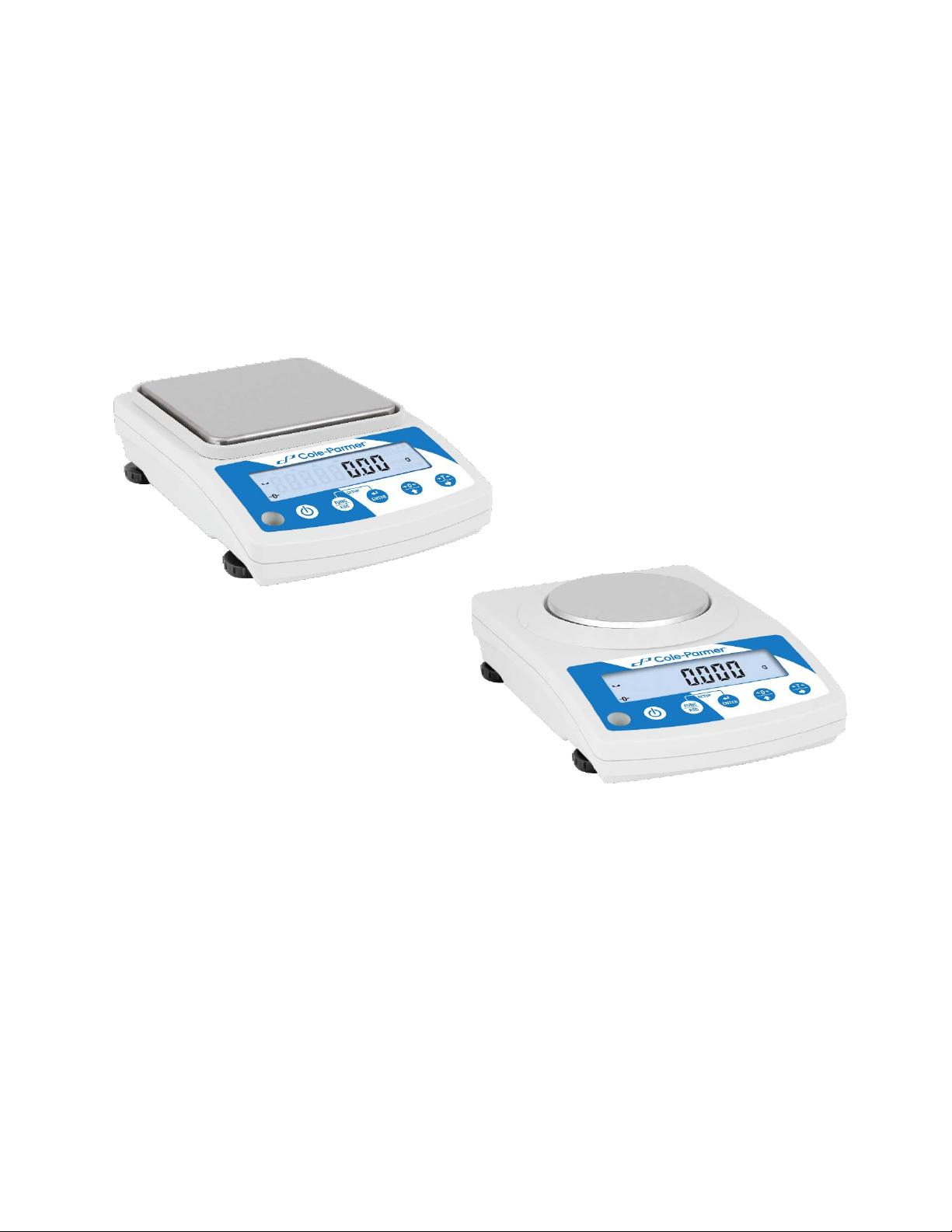
Cole-Parmer Symmetry
Portable Lab Balances: PB L Series
6-5-18 v5
Page 2
GENERAL INFORMATION .................................................................................................................................1
INDEX
INTENDED USE ....................................................................................................................................1
PRECAUTIONS .....................................................................................................................................1
BATTERY ..............................................................................................................................................1
WARRANTY CONDITIONS ....................................................................................................................1
UNPACKING AND INSTALLATION ....................................................................................................................2
PLACE OF USE AND ASSEMBLING....................................................................................................2
STANDARD DELIVERY COMPONENTS LIST .....................................................................................2
UNPACKING ..........................................................................................................................................2
BALANCE ASSEM BL Y ..........................................................................................................................3
BALANCE LEVELIN G ...........................................................................................................................4
POWERING THE DEVICE ....................................................................................................................4
BATTERY STATUS ...............................................................................................................................5
BATTERY POWER ................................................................................................................................5
BALANCE CONTROL .........................................................................................................................................5
BALANCE KEYBO ARD .........................................................................................................................6
NAVIGATING BALANCE MENUS .........................................................................................................6
BALANCE MENU ...................................................................................................................................7
WEIGHING MODE ...............................................................................................................................................9
UNITS ................................................................................................................................................. 10
START UNIT ....................................................................................................................................... 10
TEMPORARY UNIT ............................................................................................................................ 10
TARING .............................................................................................................................................. 11
MANUAL TARE ENTERING ............................................................................................................... 11
ZEROING ............................................................................................................................................ 12
BALANCE PARAMETERS ............................................................................................................................... 12
FILTER LEVEL ................................................................................................................................... 12
VALUE RELEASE............................................................................................................................... 12
BALANCE AMBIENT CONDITIONS .................................................................................................. 13
AUTOZERO ........................................................................................................................................ 13
TARE .................................................................................................................................................. 13
LAST DIGIT ........................................................................................................................................ 14
ADJUSTMENT .................................................................................................................................................. 14
EXTERNAL ADJUSTMENT ................................................................................................................ 14
USER ADJUSTMENT ......................................................................................................................... 16
ADJUSTMENT REPORT .................................................................................................................... 16
WORKING MODES ........................................................................................................................................... 16
RUNNING WORKING MODE ............................................................................................................. 17
WORKING MODE ACCESSIBILITY ................................................................................................... 17
SAVE MODE ....................................................................................................................................... 18
AUTOMATIC PRINTOUT TIME INTERVAL ....................................................................................... 19
LO THRESHOLD ................................................................................................................................ 19
WEIGHING ......................................................................................................................................... 20
7.6.1 SETTINGS .......................................................................................................................................... 20
7.7 . PARTS COUNTING .................................................................................................................................. 20
7.7.1 SETTINGS .......................................................................................................................................... 20
7.7.2 OPERATION MODE ........................................................................................................................... 21
7.7.3 SETTING REFERENCE MASS BY ENTERING MA SS OF A SING LE PART .................................. 21
7.7.4 SETTING REFERENCE MASS BY DETERMING MASS OF A SINGLE PART ............................... 21
7.8 . +/- CONTROL ............................................................................................................................................ 22
7.8.1 SETTINGS .......................................................................................................................................... 22
7.8.2 DECLARING CHECKWEIGHING THRESHOLDS ............................................................................. 22
7.9 . PERCENT WEIGHING AGAINST REFERENCE SAMPLE MASS ........................................................... 23
7.9.1 SETTINGS .......................................................................................................................................... 23
Page 3
7.9.2 OPERATION MODE ........................................................................................................................... 23
7.9.3 REFERENCE SAMPLE MASS DETERMINED BY WEIGHING ........................................................ 24
7.9.4 REFERENCE SAMPLE MASS DETERMINED BY ENTERING MASS VALUE ................................ 24
7.10 PEAK HOLD ....................................................................................................................................... 24
7.10.1 SETTINGS ........................................................................................................................................ 24
7.10.2 MEANS OF OPERATION................................................................................................................. 25
7.11 TOTALIZING ....................................................................................................................................... 25
7.11.1 SETTINGS ........................................................................................................................................ 25
7.11.2 MEANS OF OPERATION................................................................................................................. 25
INTERFACES ................................................................................................................................................... 26
RS232 ................................................................................................................................................. 26
8
.1.1 BAUD RATE ....................................................................................................................................... 27
8.1.2 PARITY ............................................................................................................................................... 27
USB A PORT ...................................................................................................................................... 27
8
.2.1 IMPORT / EXPORT ............................................................................................................................ 28
USB B PORT ...................................................................................................................................... 29
PERIPHERALS ................................................................................................................................................. 29
COMPUTER ....................................................................................................................................... 29
9.
1.1 COMPUTER PORT ............................................................................................................................ 29
9.1.2 CONTINUOUS TRANSMISSION ....................................................................................................... 29
9.1.3 PRINTOUT INTERVAL FOR CONTINUOUS TRANSMISSION ........................................................ 30
9.2 PRINTER ..................................................................................................................................................... 30
9.2.1 PRINTER PORT ................................................................................................................................. 30
PRINTOUTS ................................................................................................................................................ 30
ADJUSTMENT REPORT PRINTOUT ................................................................................................ 30
GLP PRINTOUT .................................................................................................................................. 31
BALANCE SETTINGS ................................................................................................................................ 32
BACKLIGHT ........................................................................................................................................ 32
'BEEP' SOUND ................................................................................................................................... 32
AUTOMATIC SHUTDOWN ................................................................................................................ 33
DATE .................................................................................................................................................. 33
TIME ................................................................................................................................................... 33
DATE FORMAT .................................................................................................................................. 34
TIME FORMAT ................................................................................................................................... 34
USER MENU DEFAULT SETTINGS .................................................................................................. 34
INFORMATION ........................................................................................................................................... 34
APPENDIX .................................................................................................................................................. 35
BALANCE SPECIFICATIONS ............................................................................................................ 35
MAITENANCE .................................................................................................................................... 35
1
3.2.1 CLEANING ABS COMPONETS ....................................................................................................... 35
13.2.2 CLEANING STAINLESS STEEL COMPONETS ............................................................................. 36
ACCESSORIES .................................................................................................................................. 36
DIMENSIONS ..................................................................................................................................... 36
CONNECTORS .................................................................................................................................. 37
TROUBLESHOOTING ........................................................................................................................ 38
ERROR MESSAGES .......................................................................................................................... 38
WARRANTY CARD ............................................................................................................................ 38
1
Page 4
GENERAL INFORMATION
I NT ENDED USE
The PBL-Series precision balance enables fast and accurate mass measurements under
laboratory conditions.
The weighing pan, made of stainless steel and equipped with anti-draft shield, is an integral part of
the PBL-series balance. Backlit LCD display ensures clear measurement result. The PBL-Series
balance is equipped with an internal battery (comes standard), so it does not have to be connected
to the mains.
The PBL-series balance is equipped with the following interfaces: RS 232, USB type A, USB type
B. The interfaces enable cooperation between the balance and peripheral devices (e.g. printer,
computer, flash drive).
PRECAUTIONS
• Prior to first use, it is highly recommended to carefully read this User Manual, and
operate the balance as intended.
• Do not use the balance for a dynamic weighing. Even if small quantities of weighed
material are added or removed from the weighing pan of the instrument, the reading
should be taken only after stabilization of the measurement results.
• While loading the balance make sure that load is placed in the very center of the
weighing pan.
• Make sure the load does not exceed instrument’s measuring range (maximum
capacity).
• Do not leave heavy loads on the weighing pan for a long period of time.
• In case of failure, immediately unplug the instrument.
• Balances to be decommissioned, should be decommissioned in accordance with valid
legal regulations.
• Do not use the balance is areas endangered with explosion. The balance is not
designed to operate in EX zones.
BATTERY
The PBL-Series balance is supplied by NiMH-type battery (nickel-metal- hydrogen) of 18002800mAh capacity.
In case of prolonged storage of the balance in low temperature, the battery must be
charged.
A worn-out battery can be replaced only by the manufacturer or by the authorized
service.
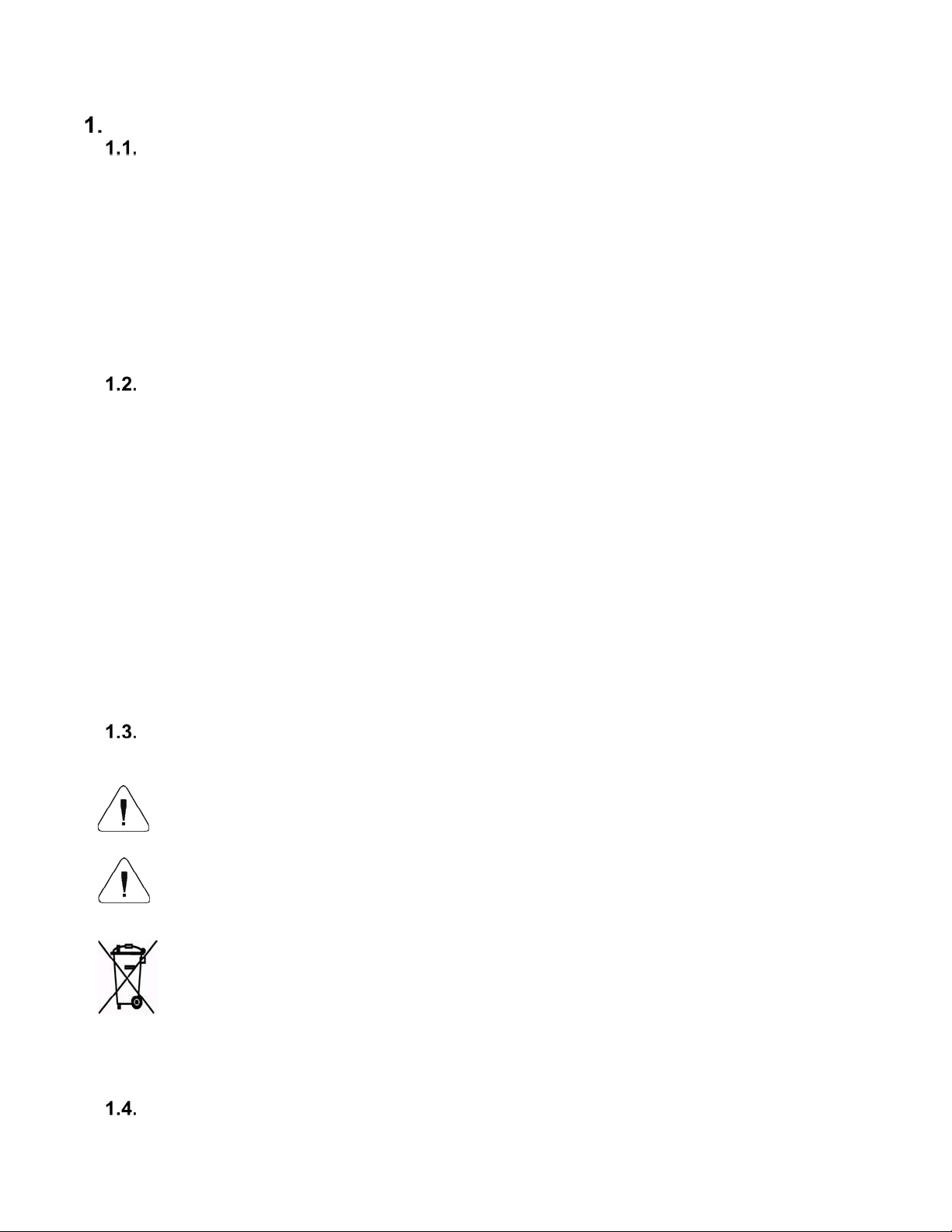
The equipment including accumulators does not belong to regular household waste.
The European legislation requires electric and electronic equipment to be collected
and disposed separately from other communal waste with the aim of being recy cled.
Notice:
Symbols on accumulators identify harmful compounds: Pb = lead, Cd = cadmium, Hg = mercury.
WARRANTY CONDITIONS
1
Page 5

Cole-Parmer will exchange, replace or repair the existing balance for any damage that appears to be
faulty by production or by construction within the 5-year warranty period.
Warranty is voided if:
A. Cole Parmer will exchange, replace or repair the existing balance for any damage that
appears to be faulty by production or by construct ion within the 5-year warranty period.
B. Warranty is voided if:
• mechanical defects caused by inappropriate use:
• defects of thermal and chemical origin,
• defects caused by lightning, overvoltage in the power network
• defects caused by water damage
• or other random event
• overloading the mechanical measuring system
• installing another version of the operating system
• utilizing the balance contrary to its intended use
• repairs carried out by non-authorized service centers
• removing or destroying protective stickers which secure the balance’s housing against
unauthorized access
C. Warranty card must be filled out for warranty to be valid.
UNPACKING AND INSTALLATION
PLACE OF USE AND ASSEMBLING
• The balance should be stored and used in locations free of vibrations and shakes, free
of air movement and dust.
• Ambient air temperature should not exceed the range of: +15 °C to +30 °C.
• Ambient relative humidity should not exceed 80%.
• During balance operation, ambient temperature in the weighing room should not change
rapidly.
• The balance should be located on a stable wall console desk or a stable working table
which is not affected by vibrations and distant from heat sources.
• Keep all package element should your device be transported in the future. Remember
that only original packaging can be used for shipping purposes. Prior to packing,
uncouple any cables, remove any separable components (weighing pan, shields,
inserts). Pack the device components into an original packaging. The original packaging
protects the equipment against potential damage during transportation.
STANDARD DELIVERY COMPONENTS LIST
• Balance and components shown in Section 2.4 depending on balance model
• Warranty Card
• USB
o User Manual
o Balance USB Driver
o RLAB Software
o USB COM Driver
UNPACKING
To unpack the system, follow the diagram below-
2
Page 6
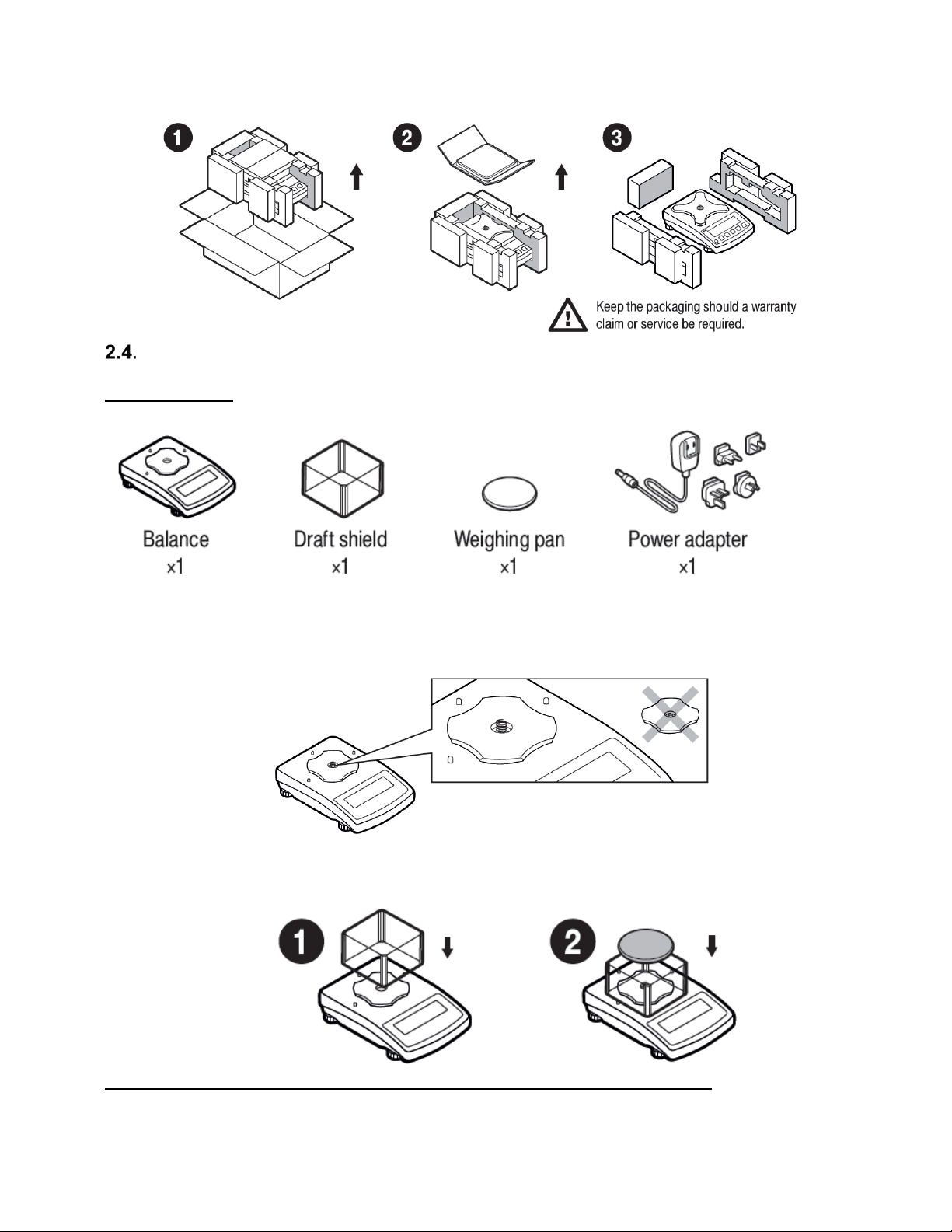
B ALANCE ASSEMBLY
Model: PBL-203
Components:
Installation:
1) Check grounding spring to insure it is in the appropriate location. Make sure that the
grounding spring juts slightly out of the hole.
2) Install components following diagram below:
i. Draft Shield
ii. Weighing Pan
Model: PBL-602, PBL-2002, PBL-3101, PBL-602.N, PBL-2002.N, PBL-3101.N
Components:
3
Page 7
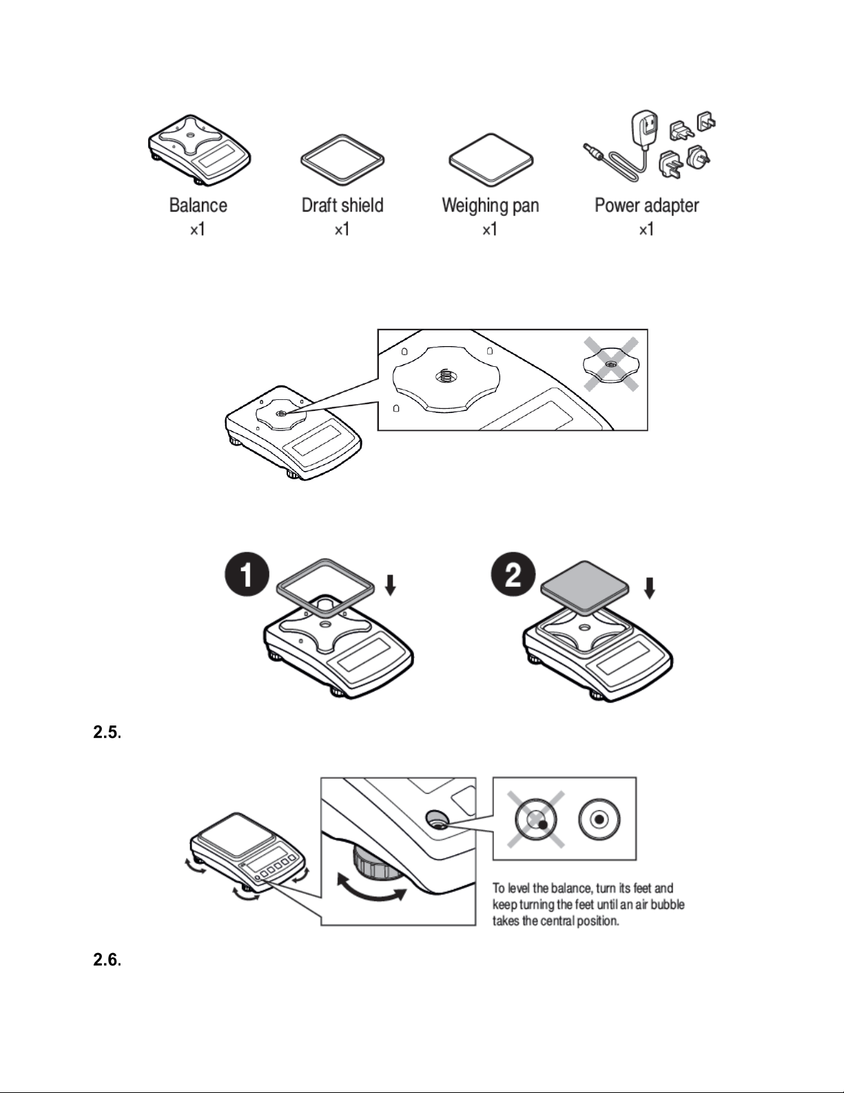
Installation:
1) Check grounding spring to insure it is in the appropriate location. Make sure that the
grounding spring juts slightly out of the hole.
2) Install components following diagram below:
i. Draft Shield
ii. Weighing Pan
BALANCE LEVELING
It is necessary to level the balance prior to plugging it in. To level the balance, turn its feet until the
air bubble is in the center position.
The balance should firmly rest on a surface, each of the feet must be supported.
POWERING THE DEVICE
Before plugging in your balance, it is imperative to wait until the balance reaches thermal stabilization
4
Page 8
(estimated 1-8 hours). On switching on, the balance requires 30 minutes of temperature stabilization
time. During temperature stabilization displayed information may change. Adjustment should be
carried out after temperature stabilization.
For correct operation of the balance the temperature range is +15˚C to +30˚C;
Any changes of temperature and humidity during operation can cause indication errors. Errors can
be corrected by carrying out user adjustment.
For balances that were stored in much lower temperatures (e.g. during winter period), thermal
stabilization period may be extended.
• Balance should be plugged in only with the power adapter that comes standard
with the model. Nominal power supply of the power adapter (specified on the
power adapter data plate) should be compatible to the power supply.
• Plug the balance in – connect the power adapter to the socket, next connect its
connector to port located at the back of the balance housing.
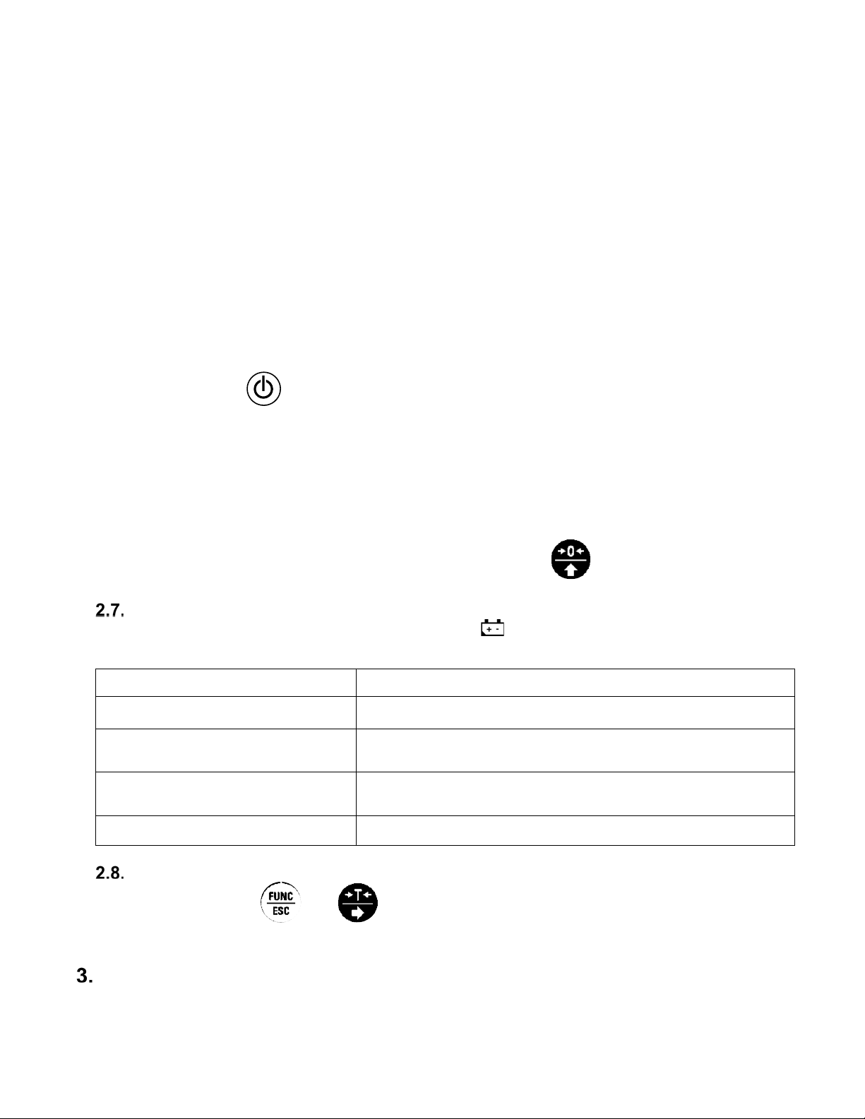
• Press button on the key pad.
! Remember to start the balance with no load on the weighing pan
• Test of the display unit takes place right after connecting the balance to the power,
all the elements and pictograms are backlit for a short time.
• Next, the name and the program number appears
• the indication gets to ZERO (displayed reading unit depends on the balance).
During the balance start, the test of an internal mass adjustment mechanism
occurs (single location and elevation of the internal mass adjustment).
• If the indication is different than zero, please press button
BATTERY STATUS
An internal battery comes standard with the balance. pictogram, displayed at the top of the
display, signals battery status.
Pictogram operation Overview
No pictogram Battery full. Standard balance operation.
Pictogram displayed continuously Battery status low. The balance will shut down.
Immediately charge the battery.
Pictogram blinks every 1 s.
Battery charging. Balance connected to power supplier,
the battery is being charged.
Pictogram blinks every 0.5 s. Battery error. Battery damaged.
BATTERY POWER
•
Simultaneously
and
keys.
• Battery power given in % is displayed for 2s.
• Wait for the home screen to be displayed.
BALANCE CONTROL
5
Page 9
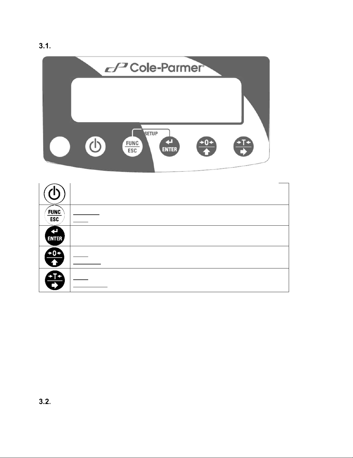
BALANCE KEYBOARD
Press to switch the balance on/off
Function: press to select working mode.
ESC: Exit out of menus/submenus
Press to send the weighing result to a printer or a computer.
Zero: press to zero the balance.
Up arrow: move up the menu or submenu
Tare: press to tare the balance.
Right arrow: enter into menu or submenu or select parameter to modify
NAVIGATING BALANCE MENUS
Use keypad to navigate in the balances menus and submenus.
6
Page 10
+
Simultaneously press to enter 'Main Menu'
Press to move upwards within balance menus and submenus
Press to enter submenu
Press to confirm introduced modifications
Press to move one menu level up
BALANCE MENU
Main menu is divided into function groups. Function group is a group of interrelated parameters.
7
Page 11

Main Menu
Submenus
Options
Overview
Additional Info
P1.
CAL
Adjustment
1.1.
CA-E
External adjustment
Section 6.1
1.2. CA
-U
User adjustment with external
weight
Section 6.2
P2. rEAd
Balance parameters
2.1.
FIL
1, 2, 3
Filter
Section 5.1
2.2.
APPr
FASt, PrEc, F_P
Value release
Section 5.2
2.3.
Enut
StAb, nStAb
Environment
Section 5.3
2.4.
Aut
YES, no
Autozero
Section 5.4
2.5.
tare
no, tArF, AtAr, EAcH
Tare
Section 5.5
2.6.
ttr
tArEH, tArnn
Tare implementing method
Section 5.5
2.7.
LdiG
ALAS, nEur, uuSt
Last digit
Section 5.6
P3. Func
Working modes
3.1.
UUGG
Weighing
Section 7.6
3.1.1.
Acc
YES, no
Working mode On/Off
Section 7.2
3.1.2.
Snn
StAb, nStAb, rEPL
Save mode
Section 7.3
3.1.3.
Int Automatic Printout Time Interval
Section 7.4
3.1.4
Lo LO Threshold
Section 7.5
3.2.
PCS
Parts counting
Section 7.7
3.2.1.
Acc
YES, no
Working mode On/Off
Section 7.2
3.2.2.
UUT
S_s, Suu
Operation mode
Section 7.7.2
3.2.3.
Snn
StAb, nStAb, rEPL
Save mode
Section 7.3
3.2.4.
Int Automatic Printout Time Interval
Section 7.4
3.2.5.
Lo LO Threshold
Section 7.5
3.3.
HiLo
+/- control
Section 7.8
3.3.1.
Acc
YES, no
Working mode On/Off
Section 7.2
3.3.2.
Snn
StAb, nStAb, rEPL
Save mode
Section 7.3
3.3.3.
Int Automatic Printout Time Interval
Section 7.4
3.3.3.
Lo LO Threshold
Section 7.5
3.4.
dEu
Percent weighing
Section 7.9
3.4.1.
Acc
YES, no
Working mode On/Off
Section 7.2
3.4.2.
UUT
S_s, Suu
Operation mode
Section 7.9.2
3.4.3.
Snn
StAb, nStAb, rEPL
Save mode
Section 7.3
3.4.4.
Int Automatic Printout Time Interval
Section 7.4
3.4.5.
Lo LO Threshold
Section 7.5
3.5.
toP
Peak hold
Section 7.10
3.5.1.
Acc
YES, no
Working mode On/Off
Section 7.2
3.5.2.
Lo LO Threshold
Section 7.5
3.6.
Add
Totalizing
Section 7.11
3.6.1.
Acc
YES, no
Working mode On/Off
Section 7.2
3.6.2.
Snn
StAb, nStAb, rEPL
Save mode
Section 7.3
3.6.3.
Int Automatic Printout Time Interval
Section 7.4
3.6.4.
Lo LO Threshold
Section 7.5
P4. Conn
Interfaces
4.1.
rS RS232 parameters settings
Section 8.1
8
Page 12

4.1.1.
bAd
2400, 4800, 9600,
19200, 38400,
RS 232 baud rate
Section 8.1.1
4.1.2.
PAr
nonE, Odd, EuEn
Parity
Section 8.1.2
P5. ducE
Peripherals
5.1.
PC
Computer
Section 9.1
5.1.1.
Prt
nonE, rS232, USbB
Computer port
Section 9.1.1
5.1.2.
Cnt
nonE, CntA, Cntb
Continuous Transmission
Section 9.1.2
5.1.3.
Int
0.1[s] - 1000[s]
Continuous transmission time
Section 9.1.3
5.2.
Prtr
Printer
Section 9.2
5.2.1.
Prt
nonE, rS232, USbb
Printer port
Section 9.2.1
P6. Prnt
Printouts
6.1.
CrEP
Adjustment report
Section 10.1
6.1.1.
CtP
YES, no
Adjustment type
6.1.2.
dAt
YES, no
Date
6.1.3.
tin
YES, no
Time
6.1.4.
Idb
YES, no
Balance S/N
6.1.5.
CdF
YES, no
Adjustment difference
6.1.6.
dSh
YES, no
Dashes
6.1.7.
SiG
YES, no
Signature
6.2.
GLP
GLP Printout
Section 10.2
6.2.1.
dAt
YES, no
Date
6.2.2.
tin
YES, no
Time
6.2.3.
n YES, no
Net
6.2.4.
t YES, no
Tare
6.2.5.
b YES, no
Gross
6.2.6.
CrS
YES, no
Current result
6.2.7.
CrP
YES, no
Adjustment report
P7. Misc
Miscellaneous
7.1. bLbt
no, 10, 20, 30, 40,
50,
100
Backlit level in [%]
Section 11.1
7.2.
bEEP
YES, no
Key sound
Section 11.2
7.3.
t1
nonE, 1, 2, 3, 5, 10
Automatic Shutdown
Section 11.3
7.4.
SdAt
Date
Section 11.4
7.5.
Stnn
Time
Section 11.5
7.6.
FdAt
1, 2, 3, 4
Date format
Section 11.6
7.7.
Ftin
12H, 24H
Time format
Section 11.7
7.8.
dFLu
User default settings
Section 11.8
P8.
InFo
Information on balance
8.1.
Idb Balance serial number
Section 12
8.2.
PurS
Program version
Section 12
P9. Unit
Units
9.1. UnSt
g, kg, N, ct, lb
Start unit
Section 4.2
9.2. Unin
g, kg, N, ct, lb
Temporary unit valid until the
balance is turned off.
Section 4.3
60, 70, 80, 90,
WEIGHING MODE
Load the weighing pan. You can read weighing result when , pictogram is displayed. To assure
long-term operation and correct mass measurements follow the rules presented below:
9
Page 13
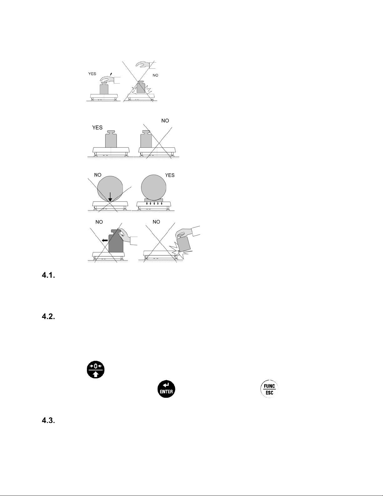
•
Load the weighing pan steadily avoiding shocks:
•
Place weighed loads centrally on the weighing pan (eccentricity errors are specified by PN-EN
45501 standard, points 3.5 and 3.6.2.):
•
Do not load the pan with concentrated force:
•
Avoid side loading, in particular side shocks:
UNITS
<P9.Unit> parameters group enables selecting start and temporary unit. Selecting unit other than [g]
is possible during weighing or during other modes operation. 'Parts counting' and 'Percent weighing'
modes are exceptions for which the unit cannot be changed.
START UNIT
Setting the start unit.
Procedure:
• To enter menu navigation, follow process found in Section 3.2 (page 7). Enter <P9.Unit /
9.1.UnSt> submenu.
•
Press
key to view available units: [g,ct,lb]
• On selecting start unit, press key to confirm. Next, press key to return to
home screen.
• The balance turns on with start unit selected.
TEMPORARY UNIT
Temporary unit remains active until the balance is turned off.
Procedure:
10
Page 14
• To enter menu navigation, follow process found in Section 3.2 (page 7). Enter <P9.Unit /
9.2.Unin> submenu.
• Press ke y to view available units: [g,ct,lb]
• On selecting start unit, press key to confirm and return to home screen
TARING
To determine net mass, put the packaging on the weighing pan. On stabilizing,
(indication changes to zero, Net pictogram is displayed in t he left upper corner):
On loading the weighing pan, net mass is displayed. You can tare repeatedly within the whole
measuring range. While using tare function remember not to exceed the maximum measuring range
of the balance. On unloading the weighing pan, the sum of tared masses with minus sing is displayed.
Caution:
Taring cannot be performed when the displayed value is negative or equal zero. In such case
message Err3 is displayed and short signal is emitted.
press
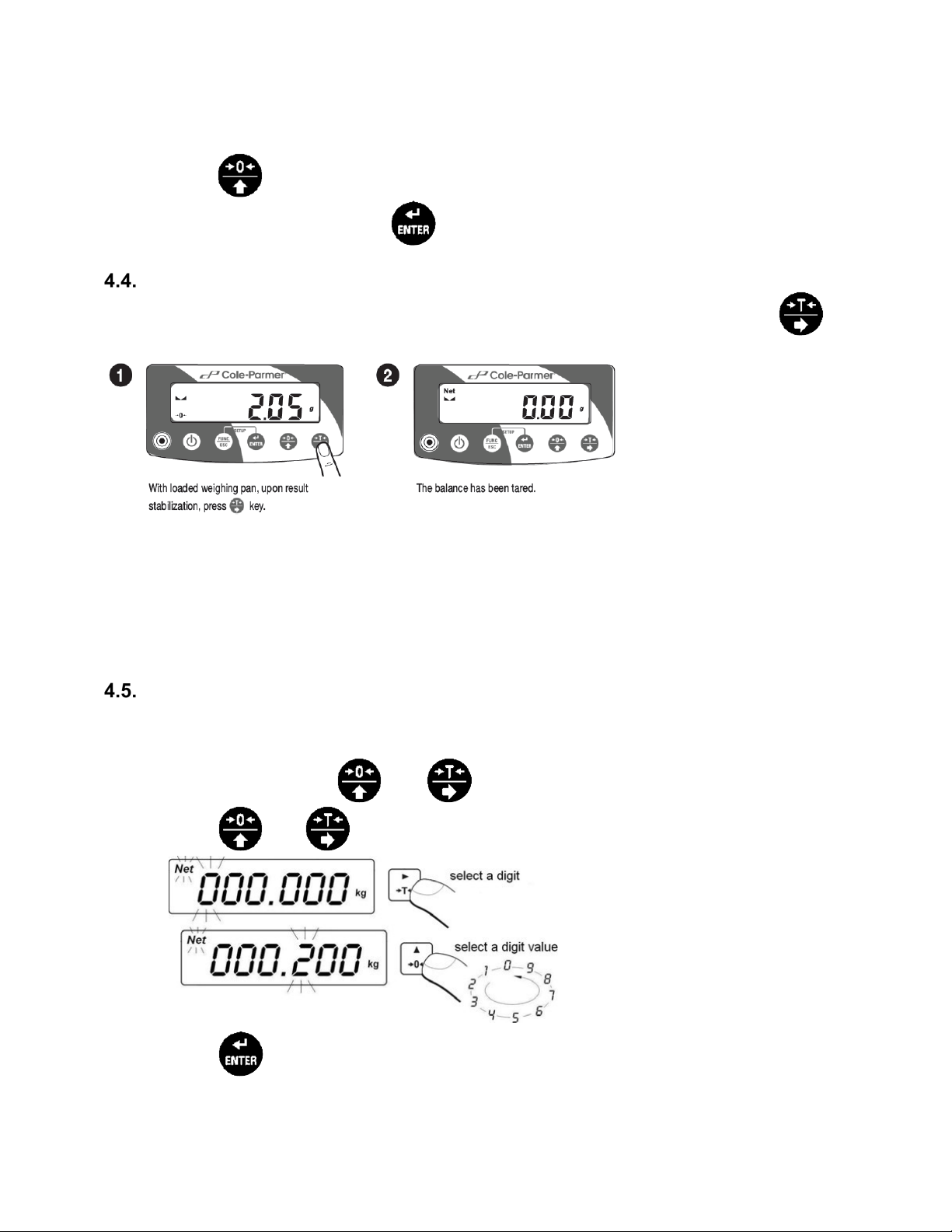
MANUAL TARE ENTERING
Manual entering of tare value within the balance.
Procedure:
key
• Simultaneously press
• Using and keys set tare value
• Press key,
• Balance returns to weighing mode. Tare value with '-' sign is displayed.
and
keys.
11
Page 15

• Tare can be entered at any moment during the weighing process.
Caution:
Tare cannot be entered manually when tare value is already implemented to balance's memory. In
such case message <Err3> is displayed and a short signal is emitted.
ZEROING
To zero mass indication press . key. Zero value and following pictograms
displayed. It is possible to zero the balance only when the
Caution:
Indication can be zeroed only within ±2% range of maximum capacity. If the zeroed value is greater
than ±2% of the maximum capacity, message <Err2> is displayed and short signal is emitted.
indication is stable.
and are
BALANCE PARAMETERS
You can adjust the balance to ambient conditions (filter level) or to your own needs (autozero, tare
value). The parameters are to be found in <P2.rEAd> submenu.
FILTER LEVEL
Filter settings adjustment depends on the working environment. For the best possible conditions,
the filter can work in fast mode. For conditions that are poor, the filter should be set to slow.
• To enter menu navigation, follow process found in Section 3.2 (page 7). Enter <P2.rEAd
/ 2.1.FiL> submenu
•
Press
1 - fast
2 - average
3 – slow
•
Press
Caution:
The higher filter level, the longer the indication takes to stabilize.
key to view available filter values:
key to confirm. Return to home screen.
VALUE RELEASE
Parameter related with the stabilization rate of measurement result. Depending on the selected
option, weighing time is either shorter or longer.
12
Page 16

Procedure:
• To enter menu navigation, follow process found in Section 3.2 (page 7). Enter <P2.rEAd
/ 2.2.APPr> submenu.
•
•
Press
F_P - Fas t and reliable
PrEc - Reliable
FASt - Fast
Press
key to view available options:
key to confirm. Return to home screen.
B ALANCE AMBIENT CONDITIONS
Parameter relating to ambient and environmental conditions in which the balance operates. If the
ambient conditions are unstable (air drafts, vibrations), select 'unstable' option.
Procedure:
• To enter menu navigation, follow process found in Section 3.2 (page 7). Enter <P2.rEAd
/ 2.3.Enut> submenu.
•
Press
nStAb – unstable
StAb –stable.
key to view available options:
•
Press
key to confirm. Return to home screen.
AUTOZERO
The balance features an autozero function (Auto) ensuring precise mass indication. This function
automatically controls and corrects zero indication.
There are, however, some cases when this function can be a disturbing factor for the measuring
process; e.g. very slow placing of a load on the weighing pan (load adding). In such case, it is
recommended to disable the function.
Procedure:
• To enter menu navigation, follow process found in Section 3.2 (page 7). Enter <P2.rEAd
/ 2.4.Aut> submenu.
•
•
Press
Press
key to view available options:
YES – function enabled
no – function disabled
key to confirm. Return to home screen.
TARE
Function enables setting appropriate parameters related with taring.
13
Page 17

Procedure:
• To enter menu navigation, follow process found in Section 3.2 (page 7). Enter <P2.rEAd
/ 2.5.tArA> submenu.
•
Press
key to view available options:
no- Basic tare mode. Set (selected) tare value is overwritten on
entering new tare value.
tArF- Last tare value is stored in balance's memory. Tare value is automatically
displayed on restarting the balance.
AtAr- Tare value is saved after the power supply is disconnected.
EAcH- Automatic taring of each approved measurement.
•
Press
key to confirm. Return to home screen.
LAST DIGIT
Function enables displaying the last digit of decimal place for a weighing result the measurement is
carried out with lesser accuracy.
Procedure:
• To enter menu navigation, follow process found in Section 3.2 (page 7). Enter <P2.rEAd
/ 2.6.LdiG> submenu.
•
Press
key to view available options:
ALAS - All d igits visible
nEur - Last digit is not displayed
uuSt - Last digit is displayed only for a stable weighing result
•
Press
key to confirm. Return to home screen.
ADJUSTMENT
In order to ensure the highest weighing accuracy, it is recommended to periodically introduce a
corrective factor of indications to balance memory, the said factor must be referred to a reference mass.
It is a balance adjustment.
Adjustment has to be carried out:
•
Prior to weighing
•
If long breaks between following measuring series occur
•
If the ambient temperature has changed dynamically
•
If the balance's place of use has changed
Types of adjustment:
•
External adjustment <1.1.CA-E> carried out with external weight of declared mass which
cannot be modified.
•
User adjustment <1.2.CA-u> carried out with any external weight of mass equal or greater than
30% of maximum capacity.
E XTERN AL ADJUSTMENT
External adjustment is carried out using external weight of class F1.
14
Page 18

Procedure:
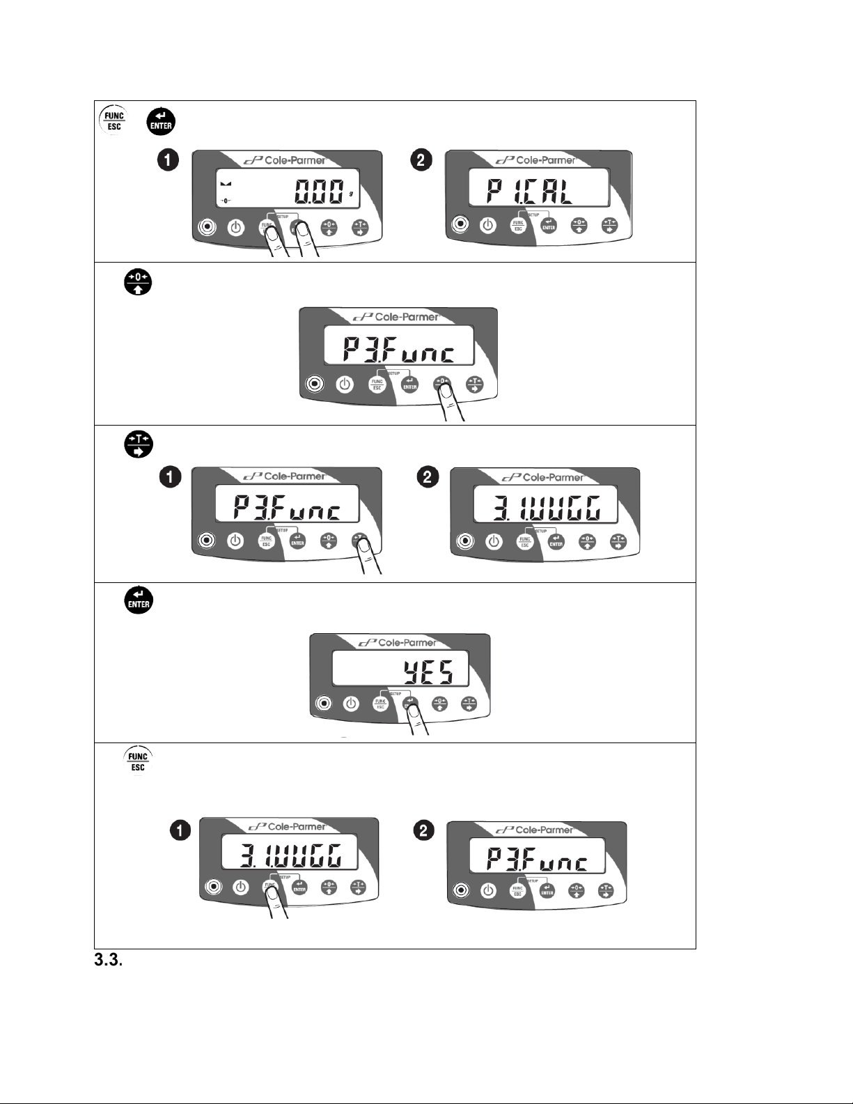
• To enter menu navigation, follow process found in Section 3.2 (page 7). Enter <P1.CAL /
1.1.CA-E> submenu.
• Message <UnLoAd> (unload the weighing pan) is displayed. On unloading the weighing
pan, press key.
• Balance starts determining mass of an empty weighing pan. The process is signaled by
dashes <- >. Next, message <Load> (put weight) is displayed along with mass value to
be put onto weighing pan; e.g.. 200.000g (depending on balance type). Put the weight of
a given mass and press key.
• Balance starts determining mass of a weight. The process is signaled by dashes <- >.
Next, message <UnLoad> (remove weight) is displayed.
15
Page 19

• On unloading the weighing pan, submenu <1.1.CA-E> is displayed.
US ER ADJUSTMENT
User adjustment is carried out using external weight of class F1.
Procedure:
• To enter menu navigation, follow process found in Section 3.2 (page 7). Enter <P1.CAL /
1.2.CA-u> submenu. Message box for entering mass of a weight used for user
adjustment is displayed. Mass of the weight has to be equal or greater than 30% of
maximum capacity.
• On entering and confirming the weight mass, message <UnLoAd> (unload the weighing
pan) is displayed.
• On unloading the weighing pan, press key.
• Balance starts determining mass of an empty weighing pan. The process is signaled by
dashes <- >. Next, message <Load> (put weight) is displayed along with declared mass
value to be put onto weighing pan; e.g.. 100.000g.
• Put the weight of a given mass and press key.
• Balance starts determining mass of a weight. The process is signaled by dashes <- >.
Next, message <UnLoad> (remove weight) is displayed.
• On unloading the weighing pan submenu<1.2.CA-u> is displayed.
ADJUSTMENT REPORT
Adjustment report is automatically printed on a printer connected to the balance at the end of each
adjustment. Report content is to be declared in <P6.1.CrEP> menu and described further down
this user manual.
WORKING MODES
The balance features the following working modes:
16
Page 20

•
Weighing <UUGG>
•
Parts counting <PCS>
•
+/- control <HiLo>
•
Percent weighing <dEu>
•
Peak hold <toP>
•
Totalizing <Add>
RUNNI NG WORKING MODE
Procedure:
Caution:
The balance is restarted with the last working mode activated.
WORKING MODE ACCESSIBILITY
Within each working mode, accessibility of the working mode can be adjusted.
YES – working mode enabled
no- working Mode Disabled
Procedure:
17
Page 21

Manual printout of stable weighing result and <6.2.GLP> parameter's settings. While
to be printed on measurement stabilization.
rEPL
Automatic printout of the first stable weighing result above <Lo> threshold.
SAVE MODE
You can declare method of sending the information from the balance to a peripheral device (printer,
computer).
Procedure:
Select option for sending of data:
StAb
nStAb
pressing key when the result is unstable (no pictogram displayed), the result is
Manual printout of each weighing result and <6.2.GLP> parameter's settings. In case
when the result is unstable, <?> sign is displayed at the beginning of mass frame.
Caution:
Option not available for Peak Hold working mode.
18
Page 22

AUTOMATIC PRINTOUT TIME INTERV AL
Parameter enabling you to set frequency of automatic printout. Printout interval is set in minutes with
1 [min] accuracy within 1 [min] - 1440 [min] range.
Utilize and to set interval time in minutes within 1 [min] – 1440 [min]. To confirm value
press .
Caution:
Option not available for Peak Hold working mode.
LO THRESHOLD
<Lo> parameter allows you to configure the function of automatic operation. In order to save the
next measurement, before carrying it out the mass indication must get below the set net value of Lo
threshold.
19
Page 23

Utilize and to set Lo threshold value for automatic operation. To confirm value press
.
WEIGHING
<UUGG> (Weighing) mode is a standard working mode that enables carrying out weighing’s and
saving them to the database.
7.6.1 SETTINGS
• Accessibility of <UUGG> (Weighing) mode is declared within <P3.1.1Acc>, procedure found
within section 7.2
• Method of sending data to peripheral device is declared within <3.1.2.Snn>, procedure found
within section 7.3.
• Method of setting automatic printout time for sending data to peripheral device is declared
within <3.1.3.Snn>, procedure found within section 7.4.
• Method of setting lo threshold value for automatic operation is declared within <3.1.4.Lo>,
procedure found within section 7.5.
7.7 . PARTS COUNTING
Standard balance features parts counting option. Parts of the same mass are counted based on
determined and reference mass of a single part.
7.7.1 SETTINGS
• Accessibility of <PcS> (Parts Counting) mode is declared within <P3.2.1Acc>,
procedure found within section 7.2
• Method of sending data to peripheral device is declared within <3.2.2.Snn>, procedure found
within section 7.3.
• Method of setting automatic printout time for sending data to peripheral device is declared
within <3.2.3.Snn>, procedure found within section 7.4.
• Method of setting lo threshold value for automatic operation is declared within <3.2.4.Lo>,
procedure found within section 7.5.
20
Page 24

7.7.2 OPERATION MODE
Parameter allowing you to select method of determination of sample piece mass.
Procedure:
• To enter menu navigation, follow process found in Section 3.2 (page 7). Enter <3.2.PcS /
3.2.2.UUt> submenu.
• Press key, parameter values are displayed successively one by one:
S_S Select to set sample mass by determining mass of a single part.
Suu Select to set sample mass by entering mass of a single part.
• Enter respective value and press key to confirm, then continue weighing.
7.7.3 SETTING REFERENCE MASS BY ENTERING MASS OF A SINGLE PART
Procedure:
• To enter menu navigation, follow process found in Section 3.2 (page 7). Enter <3.2.PcS /
3.2.2.UUt> submenu, set <Suu> value.
• Enter <PcS> working mode (parts counting), first, text <SEt_Ut> is displayed for 1 s, next,
window for entering mass value of a single part.
• Enter respective value and
automatically with quantity of parts loaded onto the weighing pa n (pcs).
Caution:
If entered mass of a single part is greater than maximum capacity, message
<Err Hi> is displayed.
press
key to c onfirm. Hom e screen is displayed
7.7.4 SETTING REFERENCE MASS BY DETERMING MASS OF A SINGLE PART
Procedure:
• To enter menu navigation, follow process found in Section 3.2 (page 7). Enter <3.2.PcS /
3.2.2.UUt> submenu, set <s_s> value.
• Enter <PcS> working mode (parts counting), blinking value of sample quantity is
displayed. Blinking quantity of parts is displayed.
• Press key and select an option:
10 - Reference quantity:10 parts.
20 - Reference quantity:20 parts.
50 - Reference quantity:50 parts.
100 - Reference quantity:100 parts.
0000 - Any reference quantity: - enter a value.
21
Page 25

•
Press
window is displayed:
• If the parts are to be weighed in a container, first put it on a weighing pan and next tare it.
• Load the weighing pan with declared amount of parts. When the indication is stable (
pictorgram is displayed) press key to confirm the mass.
• Mass of a single part is automatically calculated and next quantity of parts (pcs) is
displayed:
Remember:
• Maximum mass of all parts on the weighing pan cannot be greater than maximum
capacity.
• Mass of a single part has to be equal or greater than 0.1 reading unit of the balance. If
the abovementioned condition is not fulfilled, message <Err Lo> is displayed.
• During parts counting determination wait until pictogram is displayed. Next, confirm
declared quantity of parts.
key to confirm. Message <LoAd> is displayed for 1 s. Next, the following
7.8 . +/- CONTROL
+/- control working mode enables entering checkweighing thresholds values (Min, Max).
7.8.1 SETTINGS
• Accessibility of <HiLo> (+/- Control) mode is declared within <P3.3.1Acc>, procedure found
within section 7.2
• Method of sending data to peripheral device is declared within <3.3.2.Snn>, procedure found
within section 7.3.
• Method of setting automatic printout time for sending data to peripheral device is declared
within <3.3.3.Snn>, procedure found within section 7.4.
• Method of setting lo threshold value for automatic operation is declared within <3.3.4.Lo>,
procedure found within section 7.5.
7.8.2 DECLARING CHECKWEIGHING THRESHOLDS
Procedure:
• To enter menu navigation, follow process found in Section 3.2 (page 7). Enter “+/-
control” <HiLo> working mode.
• Message <SEt Lo> is displayed for 1s. Next, a message box for entering low threshold
(Min) value is displayed.
22
Page 26

• Enter the value and press key to confirm. Message <SEt Hi> is
s. Next, a message box for declaring high threshold (Max) is displayed.
displayed for 1
• Enter the value and press ke y to confirm. Working mode home screen is
displayed. Threshold value is displayed in the upper part of the display.
Caution:
<Err Lo> message is displayed:
• If value of entered low threshold (Min) is greater than high threshold value (Max).
<Err Hi> message is displayed:
• If value of entered high threshold (Max) is greater than the maximum capacity.
7.9 . PERCENT WEIGHING AGAINST REFERENCE SAMPLE MASS
Working mode enables comparison of a measured sample with the reference mass. The result is
expressed in [%]. Reference mass can be determined by weighing or entered to balance's memory.
7.9.1 SETTINGS
• Accessibility of <dEu> (% Weighing) mode is declared within <P3.4.1Acc>, procedure
found within section 7.2
• Method of sending data to peripheral device is declared within <34.2.Snn>, procedure found
within section 7.3.
• Method of setting automatic printout time for sending data to peripheral device is declared
within <3.4.3.Snn>, procedure found within section 7.4.
• Method of setting lo threshold value for automatic operation is declared within <3.4.4.Lo>,
procedure found within section 7.5.
7.9.2 OPERATION MODE
Parameter allowing you to select method of determination of sample piece mass.
Procedure:
• To enter menu navigation, follow process found in Section 3.2 (page 7). Enter <3.4.dEu
/ 3.4.2.UUt> submenu.
• Press key, parameter values are displayed successively one by one:
S_S Select to set reference sample mass by determining the mass value.
Suu Select to set reference sample mass by entering the mass value.
• Enter respective value and press key to confirm, then continue weighing.
23
Page 27

7.9.3 REFERENCE SAMPLE MASS DETERMINED BY WEIGHING
Procedure:
• To enter menu navigation, follow process found in Section 3.2 (page 7). Enter <3.4.dEu /
3.4.2.UUt> submenu, set <s_s> value.
• Enter <dEu> working mode (Percent weighing).
• Message <Load> is displayed for 1s. Next, the following window is displayed:
• Load the weighing pan with reference sample. When the indication is stable (
pictogram is displayed) press key to confirm the mass.
• Value of weighed load is automatically entered as reference mass. Next, home screen
with 100.000% value is displayed.
7.9.4 REFERENCE SAMPLE MASS DETERMINED BY ENTERING MASS VALUE
Procedure:
• To enter menu navigation, follow process found in Section 3.2 (page 7). Enter <3.4.dEu /
3.4.2.UUt> submenu, set <Suu> value.
• Enter <dEu> working mode (Percent weighing).
• Message <SEt_Ut> is displayed for 1s. Next, a message box for entering mass value is
displayed.
• Enter respective reference sample mass value.
•
Press
Caution:
If entered reference mass value is greater than maximum capacity, message
<Err Hi> is displayed.
key to confirm. Home screen with 0.000% value is displayed.
7.10 PEAK HOLD <toP> function enables snapping value of maximum force applied to the weighing pan during
one loading.
7.10.1 SETTINGS
• Accessibility of <toP> (Peak) mode is declared within <P3.5.1Acc>, procedure found within
section 7.2
• Method of setting lo threshold value for automatic operation is declared within <3.5.2.Lo>,
procedure found within section 7.5.
24
Page 28

7.10.2 MEANS OF OPERATION
Procedure:
• To enter menu navigation, follow process found in Section 3.2 (page 7). Enter <3.5.toP /
3.5.2.Lo> submenu, set <Lo> parameter value (Lo threshold) after exceeding of which
maximum force is to be registered.
• Enter 'Peak hold' <toP> working mode.
• From now on the balance registers and holds every single weighment which is above the
<Lo> threshold, and which is higher than the result of the previous peak hold.
• If the balance detects mass above the threshold, the highest detected indication is held on
the main display and the pictogram <Max> is shown on the right, over the measuring unit.
• The start of the next process of peak hold measurement is possible only after removing the
load from the weighing pan and pressing key. This causes returning to the home
screen of <toP> mode. Pictogram <Max> is automatically deleted.
7.11 TOTALIZING
Working mode enables mass totaliz ing of weighed ingredients and printing totaliz ing report on a printer
connected to the balance. It is possible to totalize max. 30 weighing’s (ingredients) in one process.
7.11.1 SETTINGS
• Accessibility of <Add> (Totalizing) mode is declared within <P3.6.1Acc>, procedure found
within section 7.2
• Method of sending data to peripheral device is declared within <3.6.2.Snn>, procedure found
within section 7.3.
• Method of setting automatic printout time for sending data to peripheral device is declared
within <3.6.3.Int>, procedure found within section 7.4.
• Method of setting lo threshold value for automatic operation is declared within <3.6.4.Lo>,
procedure found within section 7.5.
7.11.2 MEANS OF OPERATION
Procedure:
• Enter 'Totalizing' <Add> mode. A blinking '▲' pictogram is displayed in the upper part of
the display.
• If the ingredients are to be weighed in a container, first put it on a weighing pan and next
tare it.
• Load the weighing pan with first ingredient. When the indication is stable ( pictogr am is
displayed) press key to confirm its mass.
• Weighing’s sum and '▲' pictogram are displayed continuously.
• Unload the weighing pan. ZERO indication is displayed and pictogram “▲” starts to blink.
25
Page 29

• Load the weighing pan with another ingredient. On indication stabilization press
key.
• Sum of first and second weighing’s and “▲” pictogram are displayed continuously.
•
Press
“Print?” <Prnt?> is displayed.
•
Press
balance.
Example report:
key to finish the process (with loaded or unloaded weighing pan). Message
key. Sum of all saved weighing’s is printed on a printer connected to the
•
Press
• This causes returning to home screen of <Add> mode and automat ic zeroing of data on
carried out measurements.
Caution:
In case of exceeding display range of totalized mass on balance's display, message <Hi> is
displayed. Remove the ingredient from the weighing pan and finish the process. Load the weighing
pan with smaller mass that does not exceed display range of totalized mass.
key to print the report again. Press key to exit.
INTERFACES
<P4.Conn> menu enables configuration of ports settings. The balance can communicate with a
peripheral device, the communication is established via the following interfaces: RS232, USB type A,
USB type B. USB type B port is used for connecting a computer. USB type A port is used for connecting
a printer of a flash drive.
RS232
In <P4.Conn> menu, the following RS232 transmission parameters can be set:
• Baud rate
• Parity
26
Page 30

8.1.1 BAUD RATE
Procedure:
• To ent er menu navigation, follow process found in Section 3.2 (page 7). Enter <P4.Conn
/ 4.1.rS / 4.1.1.bAd> submenu.
•
Press
•
Press
8.1.2 PARITY
Procedure:
• To enter menu navigation, follow process found in Section 3.2 (page 7). Enter <P4.Conn
/ 4.1.rS / 4.1.2.PAr> submenu.
key to view available options:
2400
9600
19200
38400
57600
115200
key to confirm. Return to home screen.
•
•
Press
Press
key to view available options:
nonE – none
EuEn – even
Odd – odd
key to confirm. Return to home screen.
USB A PORT
USB port of type A is intended for:
• Connecting a USB flash drive in order to enable:
- operator's parameters export/import
- weighing reports export
- Alibi reports export
• Connecting scale to PCL printer
• Connecting printer (featuring USB port)
Caution:
The USB flash drive must support FAT files system.
27
Page 31

8.2.1 I MPORT / EXPOR T
Function enabling you to archive weighing reports and Alibi reports, and to copy parameters
between weighing devices of the same series. Import/export operation can be carried out by means
of USB flash drive comprising <FAT files system>. Upon connection of the USB flash drive to the
USB A port, the drive gets detected automatically, as a result <IE> submenu is created.
Since extensions of exported weighing reports and Alibi reports files are specific, and the file-stored
data is encoded, therefore the files content is not readable for standard computer programs. Please
contact your Cole Parmer representative for the software.
Weighing Record Export
Option enabling you to export weighings to a USB flash drive. Weighing device program offers
option of record of 100 000 weighings.
Procedure:
• Connect the USB flash drive to USB A port.
• Enter <IE / IE1.UUE> submenu.
• The program automatically saves exported data to a USB flash drive file.
File name and extension: xxxxxx.wei, where xxxxxx – serial number.
ALIBI Weighing Record Export
Option enabling you to export ALIBI weighings to a USB flash drive. Weighing device program
offers option of record of 500 000 weighings.
Procedure:
• Connect the USB flash drive to USB A port.
• Enter <IE / IE2.ALE> submenu.
• The program automatically saves exported data to a USB flash drive file.
File name and extension: xxxxxx.ali, where xxxxxx – serial number.
Parameters Export/Import
Export / import of all user parameters between weighing devices of the same series carried out
using USB flash drive.
Export Procedure:
• Connect the USB flash drive to USB A port
• Enter <IE / IE3.SPE> submenu.
• The program automatically saves exported data to a USB flash drive file.
File name and extension: xxxxxx.par, where xxxx xx – serial number.
Import Procedure:
• Connect the USB flash drive to USB A port, make sure that the drive stores paramters file in
the main directory (file name: xxxxxx.pa r, where xxxxxx – serial number).
• Enter <IE / IE4.SPI> submenu.
• User parameters are automatically imported from xxxxxx.par file
28
Page 32

USB B PORT
USB port of type B is intended for connecting the scale to a computer. In order to make connection
of scale and computer possible, it is necessary to install virtual COM port in a computer. To carry out
this procedure, you need a respective driver installer which is included on the USB driver included
with the balance.
Procedure:
1. After virtual COM port is installed on computer, enter < P5.ducE / 5.1.PC / 5.1.1.Prt>
submenu and set <USbb> value.
2. Run program for measurements readout.
3. Set communication parameters – select COM port
4. Start cooperation.
PERIPHERALS
<P5.ducE> menu comprises list of devices that can cooperate with the balance.
COMPUTER
In <5.1.PC> menu you can:
• Select interface to which a computer with program enabling computer- balance
communication is connected.
• Enable or disable continuous transmission.
• Set time interval for printouts during continuous transmission.
9.1.1 COMPUTER PORT
Procedure:
• To enter menu navigation, follow process found in Section 3.2 (page 7). Enter <5.1.PC /
5.1.1.Prt> submenu.
•
Press
key to view available options:
nonE – none
rS232 – RS232
USbB – USB type B
•
Press
key to confirm. Return to home screen.
9.1.2 CONTINUOUS TRANSMISSION
Procedure:
• To enter menu navigation, follow process found in Section 3.2 (page 7). Enter <5.1.PC /
5.1.2.Cnt> submenu.
•
•
Press
Press
key to view available options:
nonE - Continuous transmission disabled
CntA - Continuous transmission in basic unit.
Cntb - Continuous transmission in current unit.
key to confirm. Return to home screen.
29
Page 33

9.1.3 PRINTOUT INTERVAL FOR CONTINUOUS TRANSMISSION
No.
Name
Overview
6.1.1.
CtP
Adjustment type
6.1.2.
dAt
Adjustment date
6.1.3.
tin
Adjustment time
6.1.4.
Idb
Balance serial number
last adjustment and mass of currently measured adjustment weight.
6.1.6.
dSh
Line separating data and signature fields on a printout.
6.1.7.
SiG
An area for the signature of a user performing the adjustment.
Interval for printouts is set in seconds with 0.1[s] accuracy. You can set any interval value
ranging from 0.1 to 3600 seconds.
Procedure:
• To enter menu navigation, follow process found in Section 3.2 (page 7). Enter <5.1.PC /
5.1.3.Int> submenu. Message box for entering interval value is displayed.
•
Press
key to confirm. Return to home screen.
9.2 PRINTER
<5.2.Prtr> menu enables selecting port to which data is send on pressing
data is set in <P6.Prnt> submenu and described further down this user manual.
9.2.1 PRINTER PORT
Procedure:
• To enter menu navigation, follow process found in Section 3.2 (page 7). Enter <5.2.Prtr /
5.2.1.Prt> submenu.
•
•
Press
nonE - None
rS232 - RS232 port
USbB - USB type B port for connecting a computer.
Press
key to view available options:
key to confirm. Return to home screen.
PRINTOUTS
<P6.Prnt> menu enables defining printout templates of:
•
Adjustment report
•
GLP printout
ADJUSTMENT REPORT PRINTOUT
<6.1.CrEP> menu enables declaring data that is to be printed on adjustment printout.
List of data to be declared:
key. Content of sent
6.1.5. CdF
Difference between mass of adjustment weight that was measured during
30
Page 34

For the parameters described above, one of these values must be selected:
No.
Name
Overview
6.2.2.
tin
Performed weighing time.
6.2.4.
t
Tare weight value of performed weighing in current unit.
6.2.5.
b Gross weight value of performed weighing in current unit.
6.2.6.
CrS
Current result (net weight value) in a current unit.
YES - Print
no - Do not print
Caution:
Printouts are printed in English
Example report:
GLP PRINTOUT
<6.2.GLP> menu enables declaring data that is to be printed on a GLP printout.
List of data to be declared:
6.2.1. dAt Performed weighing date.
6.2.3. n Net weight value of performed weighing in basic unit.
6.2.7. CrP
For the parameters described above, one of these values must be selected:
YES - Print
no - Do not print
Caution:
Printouts are printed in English
Example report:
Last adjustment report in accordance with adjustment report
printout settings.
31
Page 35

BALANCE SETTINGS
<P7.Othr> menu allows to customize the balance by setting:
•
Backlight
•
'Beep' sound - reaction to pressing a key
•
Automatic shutdown
•
Date format
•
Time format
•
User menu default settings
BACKLIGHT
<7.1.bLbt> parameter enables setting display brightness. The backlight can be disabled completely.
Procedure:
• To enter menu navigation, follow process found in Section 3.2 (page 7). Enter <P7.Misc /
7.1.bLbt> submenu.
•
Press
100 - Maximum brightness
10 - Minimum brightness
nonE - Backlight disabled.
•
Press
'BEEP' SOUND
<7.2.bEEP> parameter enables switching on/off a ‘beep’ sound responsible for informing a user
about pressing any key.
Procedure:
•
To enter menu navigation, follow process found in Section 3.2 (page 7). Enter <P7.Misc /
7.2.bEEP> submenu.
key to view available options, where:
key to confirm. Return to home screen.
•
Press
key to view available options:
no - disabled
YES - enabled
•
Press
key to confirm. Return to home screen.
32
Page 36

AUTOMATIC SHUTDOWN
<7.3.t1> parameter enables automatic shutdown of the balance, when indication is stable.
Procedure:
• To enter menu navigation, follow process found in Section 3.2 (page 7). Enter <P7.Misc /
7.3.t1> submenu.
•
•
Press
nonE - Automatic shut down disabled.
1, 2, 3, 5 ,10- Time in [min]. W hen indication is stable during set time is shuts down.
Press
key to view available options:
key to confir m . Retur n to home screen.
DATE
<7.4.SdAt> parameter enables setting current date.
Procedure:
• To enter menu navigation, follow process found in Section 3.2 (page 7). Enter <P7.Misc
/ 7.4.dAt> submenu.
• Message box is displayed:
Where:
• Press key to confirm. Return to home screen.
16 - Year
11 - Month
02 - Day
TIME
<7.5.Stnn> parameter enables setting current time.
Procedure:
• To enter menu navigation, follow process found in Section 3.2 (page 7). Enter <P7.Misc
/ 7.5.dAt> submenu.
• Message box is displayed:
Where:
12 - Hour
05 - Minute
• Press key to confirm. Return to home screen
33
Page 37

DATE FO RMAT
<7.6.FdAt> parameter enables defining date format for printouts.
Procedure:
• To enter menu navigation, follow process found in Section 3.2 (page 7). Enter <P7.Misc /
7.6.FdAt> submenu.
•
Press
1
- Date format DD.MM.YYYY
2
- Date format MM.DD.YYYY
3
- Date format YYYY.MM.DD
4
- Date format YYYY.DD.MM
•
Press
key to view available options:
key to confirm. Return to home screen.
TIME FORMAT
<7.7.Ftin> parameter enables defining time format for printouts.
Procedure:
• To enter menu navigation, follow process found in Section 3.2 (page 7). Enter <P7.Misc /
7.7.Ftin> submenu.
•
•
Press
24 H - 24 hour time format
12 H - 12 hour time format
Press
key to view available options:
key to confirm. Return to home screen.
USER MENU DEFAULT SETTINGS
<P7.8.dFLu> parameter enables setting user default settings.
Procedure:
• To enter menu navigation, follow process found in Section 3.2 (page 7). Enter <P7.Misc /
7.8.dFLu> submenu.
• Message <Cont?> (continue?) is displayed.
• Press key to confirm. Balance restores user default settings. The process is
signaled by dashes <- >.
• On process completion, balance displays <7.8.dFLu> submenu.
INFORMATION
<P8.InFo> menu comprises information on the balance. The parameters serve informative purposes:
•
Balance serial number – <8.1.Idb> parameter
•
Program version – <8.2.PurS> parameter.
•
Settings printout - <8.4.PStP> parameter
34
Page 38

APPENDIX
PBL-203
PBL-602(.N)
PBL-2002(.N)
PBL-3101(.N)
(average time)
Packaging dimensions [mm]
BALANCE SPECIFICATIONS
Catalog Number 10402-51 10402-52 10402-53 10402-54
Maximum capacity 200g 600g 2000g 3100g
Readability [d] 0.001g 0.01g 0.01g 0.1g
Tare range -200g -600g -2000g -3100g
Repeatability* 0.002g 0.01g 0.01g 0.1g
Linearity ±0.004g ±0.02g ±0.03g ±0.3g
Stabilization time 2s 2s 2s 2s
Adjustment External
Display
NTEP Verified Unit Option
IP rating IP 43 IP 43 IP 43 IP 43
RS 232
Power supply
Battery operating time
Operating temperature +15 to +30 ˚C
Weighing pan
dimensions
Interface
* - Standard deviation
NO YES YES YES
1
100 ÷ 240 V AC 50 ÷ 60 Hz / 12 V DC + battery
Ø100mm 128x128mm
USB type A, USB type B, RS 232
LCD (with backlit)
1
33h
330x230x140
1
1
MAITENANCE
Disassembly of weighing pan and other detachable components (the components differ depending
on a balance type – see: UNPACKING AND INSTALLATION sectio n ).
Caution:
Cleaning anti-draft chamber while still installed may cause damage to the measuring system.
13.2.1 CLEANING ABS COMPONETS
To clean dry surfaces and avoid smudging, use clean non-coloring cloths made of cellulose or
cotton. You can use a solution of water and detergent (soap , dishwashing d etergent, glass cleaner).
Gently rub the cleaned surface and let it dry. Repeat cleaning process if needed.
In the case when contamination is hard to remove, e.g. adhesive, rubber, resin, polyurethane foam
residues etc., you can use a special cleaning agents based on a mixture of aliphatic hydrocarbons
that do not dissolve plastics. Before using the cleanser for all surfaces, we recommend carrying out
tests. Do not use products containing abrasive substances.
35
Page 39

13.2.2 CLEANING STAINLESS STEEL COMPONETS
Avoid using cleansers containing any corrosive chemicals, e.g. bleach (containing chlorine). Do not
use products containing abrasive substances. Always remove the dirt using microfiber cloth to avoid
damage of protective coating.
In case of a daily maintenance:
1.
Remove the dirt using cloth dipped in warm water.
2.
For best results, add a little dishwashing detergent.
ACCESSORIES
Available Accessories:
• 10100-83 PO108 Cable- RS232 Cable to USB
• 10100-84 PO151 Cable- RS232 Cable to Epson Printer
• 10100-85 EPSON TM-U220D Printer
• 10100-86 Printer Paper
DIMENSIONS
Fig.1. Dimensions of PBL-203 precision balance.
36
Page 40

Fig.2. Dimensions of PBL-602(.N), PBL-2002(.N) and PBL-3101(.N) precision balances.
CONNECTORS
Interfaces view
DC IN - power outlet
RS232 - RS 232 connector
USB 2 - USB 'device' connector
USB 1 - USB 'host' connector
Pin2 – RxD
Pin3 – TxD
Pin5 – GND
RS 232 DB9/M
connector (male)
37
Page 41

TROUBLESHOOTING
the battery (batteries)
installed or installed incorrectly)
correctly (polarization)
value.
-
-
- Display range of totalized mass on balance display exceeded in 'Totalizing'
Problem Cause Solution
Battery (batteries) discharged,
The balance does not
switch on
The balance switches off
automatically
During switching on,
message 'LH' is displayed
No batteries (batteries not
't1' paramete r set to 'YES'
value (the balance switches
off automatically)
Weighing pan loaded
during switching on
ERROR MESSAGES
- E r r 2 - - Value beyond zero range.
- E r r 3 - - Value beyond tare range.
- E r r 4 -
E r r L o -
- Adjustment weight or start mass out of range (±1% for adjustment
weight, ±10 for start mass).
-
Determined mass of single part in 'Parts counting' mode too small
-
Value of 'Min' threshold is greater than value of 'Max' threshold in '+/-
control' mode.
Connect it to the mains, charge
Check if batteries are installed
In 'Misc' menu change <7.3.t1>
parameter setting to 'nonE'
Unload the weighing pan. Zero
indication is displayed.
-
Entered value of single part greater than maximum capacity in 'Parts
counting' working mode
-
E r r H i -
Entered value of 'Max' threshold greater than maximum capacity in '+/-
control' mode.
-
Entered reference mass greater than maximum capacity in '+/- control'
mode.
- E r r 8 -
- n u l l - - Zero value from converter.
- F U L L - - Weighing range exceeded.
- L H - - Start mass error, indication out of range (-5% – +15% of start mass).
- H i -
- Time of the following operations exceeded taring, zeroing, start mass
determining, adjustment process
mode
WARRANTY CARD
38
Page 42

Five-Year Limited Warranty
Cole-Parmer will exchange, replace or repair the existing balance for any damage that
appears to be faulty by production or by construction within the 5-year warranty period.
Warranty is voided if:
A. Cole Parmer will exchange, replace or repair the existing balance for any damage that
appears to be faulty by production or by construction within the 5-year warranty period.
B. Warranty is voided if:
• mechanical defects caused by inappropriate use:
• defects of thermal and chemical origin,
• defects caused by lightning, overvoltage in the power network
• defects caused by water damage
• or other random event
• overloading the mechanical measuring system
• installing another version of the operating system
• utilizing the balance contrary to its intended use
• repairs carried out by non-authorized service centers
• removing or destroying protective stickers which secure the balance’s housing against
unauthorized access
C. Warranty card must be filled out for warranty to be valid.
Cut Here_ _ _ _ _ _ _ _ _ _ _ _ _ _ _ _ _ _ _ _ _ _ _ _ _ _ _ _ _ _ _ _ _ _ _ _ _ _ _ _ _ _ _ _ _ _ _ _ _ _ _ _ _ _ _
Warranty Registration Card
(Please Return Within 30 Days)
Company or Institution Department
Contact Name Title
Street Address
City State Zip
Telephone Date Purchased
Purchased From
Model Number Serial Number
Industry Application_
What influenced you to purchase this product?
39
Page 43

For your reference and records:
Model Number
Serial Number
Purchase Date
Place Stamp
Here
Cole-Parmer
Warranty Registration
625 East Bunker Ct
Vernon Hills, IL 60061
40
Page 44

t is recommended that Cole-Parmer products are calibrated annually to ensure
I
proper function and accurate measurements; however, your quality system or
regulatory body may require more frequent calibrations. To schedule your
recalibration, please contact InnoCal, an ISO 17025 calibration laboratory
accredited by A2LA.
Phone: 1-866-INNOCAL (1-866-466-6225)
Fax:
1-847-327-2993
E-mail: sales@innocalsolutions.com
Web: InnoCalSolutions.com
For Product and Ordering Inf orm a ti on, Contact:
Toll-Free: 1-800-323-4340
Phone: 1-847-549-7600
Fax: 1-847-247-2929
41
 Loading...