

Page 1
User Manual
05-01-18 REV04
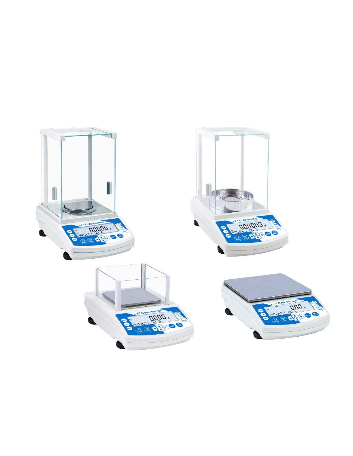
Cole-Parmer Symmetry Balances
Analytical Balances: LA, LA.C, and LA.N Series
Precision Toploading Balances: LT, LT.C, and LT.N Series
1
Page 2

2
Page 3

1. GENERAL INFORMATION ............................................................................................................................................. 6
1.1 INTENDED USE ................................................................................................................................................................... 6
1.2 PRECAUTIONS ................................................................................................................................................................... 6
1.3 SUPERVISION OVER METROLOGICAL PARAMETERS .......................................................................................................... 6
1.4 WARRANTY CONDITIONS ................................................................................................................................................... 6
2. UNPACKING AND INSTALLATION ................................................................................................................................. 7
2.1 PLACE OF USE AND ASSEMBLING ....................................................................................................................................... 7
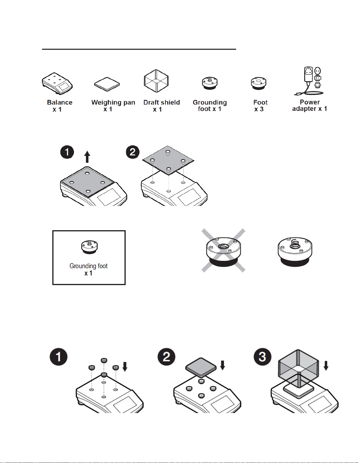
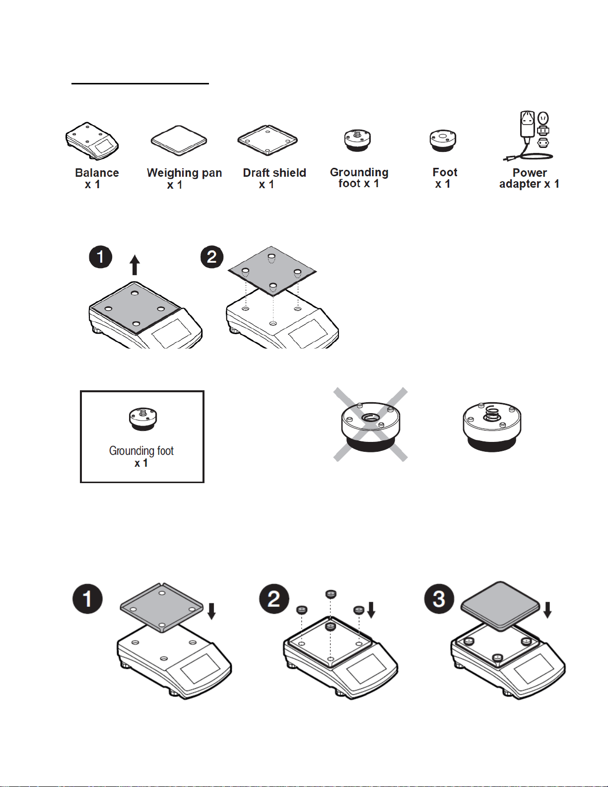
2.2 STANDARD DELIVERY COMPONENTS LIST.......................................................................................................................... 7
2.3 UNPACKING ....................................................................................................................................................................... 7
2.4 BALANCE ASSEMBLY .......................................................................................................................................................... 8
2.5 BALANCE LEVELING .......................................................................................................................................................... 13
2.6 POWERING THE DEVICE ................................................................................................................................................... 13
2.7 AMBIENT CONDITIONS STATE INDICATION (ANALYTICAL BALANCES) ............................................................................. 14
3. BALANCE CONTROL ................................................................................................................................................... 14
3.1 BALANCE KEYBOARD ........................................................................................................................................................ 14
3.2 ENTERING BALANCE MENU ............................................................................................................................................. 15
4. WEIGHING MODE ...................................................................................................................................................... 18
4.1 GOOD WEIGHING PRACTICE ............................................................................................................................................ 18
4.2 WEIGHING UNITS ............................................................................................................................................................. 19
4.3 UNITS ACCESSIBILITY ........................................................................................................................................................ 19
4.4 START UNIT SELECTION .................................................................................................................................................... 19
4.5 USER-DEFINED UNIT ........................................................................................................................................................ 20
4.6 BALANCE ZEROING ........................................................................................................................................................... 20
4.7 BALANCE TARING ............................................................................................................................................................. 21
4.7.1 MANUAL TARE DETERMINATION ............................................................................................................................. 21
4.7.2 DELETING TARE ........................................................................................................................................................ 21
4.7.3 TARE DATABASE ....................................................................................................................................................... 21
4.7.4 AUTOTARE ................................................................................................................................................................ 22
4.8 WEIGH MODE SETTINGS .................................................................................................................................................. 23
4.8.1 FILTER LEVEL SETTING .............................................................................................................................................. 24
4.8.2 VALUE RELEASE ........................................................................................................................................................ 25
4.8.3 AUTOZERO FUNCTION.............................................................................................................................................. 25
4.8.4 LAST DIGIT DISPLAY .................................................................................................................................................. 26
4.8.5 BALANCE AMBIENT CONDTIONS .............................................................................................................................. 26
5. CALIBRATION (LA.C & LT.C SERIES) ............................................................................................................................ 27
5.1 INTERNAL CALIBRATION .................................................................................................................................................. 27
5.1.1 AUTOMATIC INTERNAL CALIBRATION ...................................................................................................................... 27
5.1.2 MANUAL INTERNAL CALIBRATION ........................................................................................................................... 28
5.2 EXTERNAL CALIBRATION .................................................................................................................................................. 28
5.3 USER CALIBRATION .......................................................................................................................................................... 29
5.4 ADJUSTMENT TEST .......................................................................................................................................................... 29
6. CALIBRATION (LA & LT SERIES) .................................................................................................................................. 29
6.1 EXTERNAL CALIBRATION .................................................................................................................................................. 30
6.2 USER CALIBRATION .......................................................................................................................................................... 30
3
Page 4

7. CALIBRATION (LA.N & LT.N SERIES) ........................................................................................................................... 31
7.1 INTERNAL CALIBRATION .................................................................................................................................................. 31
7.1.1 AUTOMATIC INTERNAL CALIBRATION ...................................................................................................................... 31
7.1.2 MANUAL INTERNAL CALIBRATION ........................................................................................................................... 32
7.2 ADJUSTMENT TEST .......................................................................................................................................................... 32
8. WORKING MODES- GENERAL INFORMATION ............................................................................................................ 33
8.1 RUNNING WORKING MODE ............................................................................................................................................. 34
8.2 WORKING MODE ACCESSIBILITY ...................................................................................................................................... 34
9. PARTS COUNTING ..................................................................................................................................................... 35
9.1 SETTING REFERENCE MASS: MASS DETERMINATION FOR THE SAMPLE OF KNOWN QUANTITY ..................................... 35
9.2 SETTING REFERENCE MASS: ENTERING MASS VALUE ...................................................................................................... 36
10. CHECKWEIGHING ...................................................................................................................................................... 37
11. DOSING ..................................................................................................................................................................... 38
12. PERCENT WEIGHING .................................................................................................................................................. 39
12.1 SETTING THE REFERENCE MASS: WEIGHING REFERENCE SAMPLE ................................................................................ 39
12.2 SETTING THE REFERENCE MASS: ENTERING THE MASS VALUE ...................................................................................... 40
13. DENSITY OF SOLIDS ................................................................................................................................................... 40
14. DENSITY OF LIQUIDS ................................................................................................................................................. 42
15. ANIMAL WEIGHING ................................................................................................................................................... 44
15.1 RUNNING THE PROCESS MANUALLY ............................................................................................................................. 45
15.2 RUNNING THE PROCESS AUTOMATICALLY .................................................................................................................... 46
16. STATISTICS ................................................................................................................................................................ 47
16.1 DELETING STATISTICS ..................................................................................................................................................... 48
17. PEAK HOLD ................................................................................................................................................................ 49
18. TOTALISING ............................................................................................................................................................... 50
19. PIPETTES CALIBRATION ............................................................................................................................................. 52
20. ADDING ..................................................................................................................................................................... 56
21. DATABASES ............................................................................................................................................................... 59
21.1 USERS ............................................................................................................................................................................. 59
21.2 PRODUCTS ..................................................................................................................................................................... 60
21.3 TARES ............................................................................................................................................................................. 61
21.4 WEIGHINGS .................................................................................................................................................................... 61
21.5 ALIBI MEMORY ............................................................................................................................................................... 63
21.6 IMPORT/EXPORT OF DATABASES ................................................................................................................................... 64
21.6.1 DATABASE EXPORT ................................................................................................................................................. 65
21.6.2 DATABASE IMPORT ................................................................................................................................................ 65
22. COMMUNICATION .................................................................................................................................................... 66
22.1 RS 232 PORTS SETTING................................................................................................................................................... 66
4
Page 5

22.2 USB PORT ....................................................................................................................................................................... 66
22.3 WI-FI PORT SETTINGS (LA.C AND LT.C SERIES ONLY) ........................................................................................................ 69
23. PERIPHERAL DEVICES ................................................................................................................................................ 71
23.1 COMPUTER .................................................................................................................................................................... 71
23.2 PRINTER ......................................................................................................................................................................... 73
23.3 BARCODE READER .......................................................................................................................................................... 75
23.4 ADDITIONAL DISPLAY ..................................................................................................................................................... 75
23.5 EXTERNAL BUTTONS ...................................................................................................................................................... 75
23.6 MEASUREMENT DATA PRINTOUT .................................................................................................................................. 76
24. PRINT MODE ............................................................................................................................................................. 77
24.1 ADJUSTMENT REPORT ................................................................................................................................................... 78
24.2 HEADER, FOOTER, GLP PRINTOUTS ................................................................................................................................ 79
24.3 NON-STANDARD PRINTOUTS ......................................................................................................................................... 81
24.4. VARIABLES .................................................................................................................................................................... 83
25. ADVANCED FEATURES ............................................................................................................................................... 83
25.1 F SHORTCUT KEYS .......................................................................................................................................................... 83
25.2 BAR GRAPHS .................................................................................................................................................................. 84
25.3 BALANCE SETTINGS ........................................................................................................................................................ 85
25.3.1 MENU LANGUAGE .................................................................................................................................................. 86
25.3.2 PERMISSIONS ......................................................................................................................................................... 86
25.3.3 “BEEP” SOUND ....................................................................................................................................................... 86
25.3.4 BACKLIGHT ............................................................................................................................................................. 86
25.3.5 BACKLIGHT TURN-OFF TIME................................................................................................................................... 86
25.3.6 AUTO SWITCH-OFF ................................................................................................................................................. 87
25.3.7 DATE ....................................................................................................................................................................... 87
25.3.8 TIME ....................................................................................................................................................................... 87
25.3.9 DATE FORMAT ........................................................................................................................................................ 88
25.3.10 TIME FORMAT ...................................................................................................................................................... 88
25.3.11 AUTOTEST GLP ..................................................................................................................................................... 88
26. MAITENANCE ............................................................................................................................................................ 90
27. ACCESSORIES ............................................................................................................................................................. 93
27.1 DENSITY DETERMINATION KIT ....................................................................................................................................... 93
28. APPENDIX .................................................................................................................................................................. 97
28.1 LA.C AND LT.C SERIES ..................................................................................................................................................... 97
28.2 LA AND LT SERIES ........................................................................................................................................................... 97
28.3 LA.N AND LT.N SERIES .................................................................................................................................................... 98
28.4 DIMENSIONS .................................................................................................................................................................. 98
28.5 CONNECTORS ................................................................................................................................................................ 99
28.6 ERROR MESSAGES ........................................................................................................................................................ 100
28.7 WARRANTY CARD ........................................................................................................................................................ 100
5
Page 6

1. GENERAL INFORMATION
1.1 INTENDED USE
The balances are designed to provide accurate measurement of weighed loads, performed under
laboratory conditions.
1.2 PRECAUTIONS
• Prior to first use, it is highly recommended to carefully read this User Manual, and operate
the balance as intended.
• Do not use the balance for a dynamic weighing. Even if small quantities of weighed material
are added or removed from the weighing pan of the instrument, the reading should be taken
only after stabilization of the measurement results.
• Do not place any magnetic materials on the weighing pan, as this can cause damage to the
measuring system of the instrument.
• While loading the balance make sure that load is placed in the very center of the weighing
pan.
• Make sure the load does not exceed instrument’s measuring range (maximum capacity).
• Do not leave heavy loads on the weighing pan for a long period of time.
• In case of failure, immediately unplug the instrument.
• Balances to be decommissioned, should be decommissioned in accordance with valid legal
regulations.
• Do not use the balance is areas endangered with explosion. The balance is not designed to
operate in EX zones.
1.3 SUPERVISION OVER METROLOGICAL PARAMETERS
Metrological parameters of a balance need to be checked by an authorized user. Inspection
frequency is qualified by the ambient conditions in which a balance is used, processes carried out
and adopted quality management system.
1.4 WARRANTY CONDITIONS
A. Cole Parmer will exchange, replace or repair the existing balance for any damage that
appears to be faulty by production or by construction within the 5-year warranty period.
B. Warranty is voided if:
• mechanical defects caused by inappropriate use:
• defects of thermal and chemical origin,
• defects caused by lightning, overvoltage in the power network
• defects caused by water damage
• or other random event
• overloading the mechanical measuring system
• installing another version of the operating system
• utilizing the balance contrary to its intended use
• repairs carried out by non-authorized service centers
• removing or destroying protective stickers which secure the balance’s housing against
unauthorized access
C. Warranty card must be filled out for warranty to be valid.
6
Page 7
2. UNPACKING AND INSTALLATION
2.1 PLACE OF USE AND ASSEMBLING
• The balance should be stored and used in locations free of vibrations and shakes, free of air
movement and dust.
• Ambient air temperature should not exceed the range of: +10 °C ÷ +40 °C.
• Ambient relative humidity should not exceed 80%.
• During balance operation, ambient temperature in the weighing room should not change
rapidly.
• The balance should be located on a stable wall console desk or a stable working table which
is not affected by vibrations and distant from heat sources.
• Take special precaution when weighing magnetic objects, as part of the balance is a strong
magnet. Should such loads be weighed, use under-pan weighing option, which removes the
weighed load from area influenced by the balance’s magnet. The hook for under-pan
weighing is installed in balance’s base.
• Keep all package element should your device be transported in the future. Remember that
only original packaging can be used for shipping purposes. Prior to packing, uncouple any
cables, remove any separable components (weighing pan, shields, inserts). Pack the device
components into an original packaging. The original packaging protects the equipment
against potential damage during transportation.
2.2 STANDARD DELIVERY COMPONENTS LI ST
• Balance and components shown in Section 2.4 depending on balance model
• W ar ranty Ca rd
• USB
o User Manual
o Balance USB Driver
o RLAB Software
o USB COM Driver
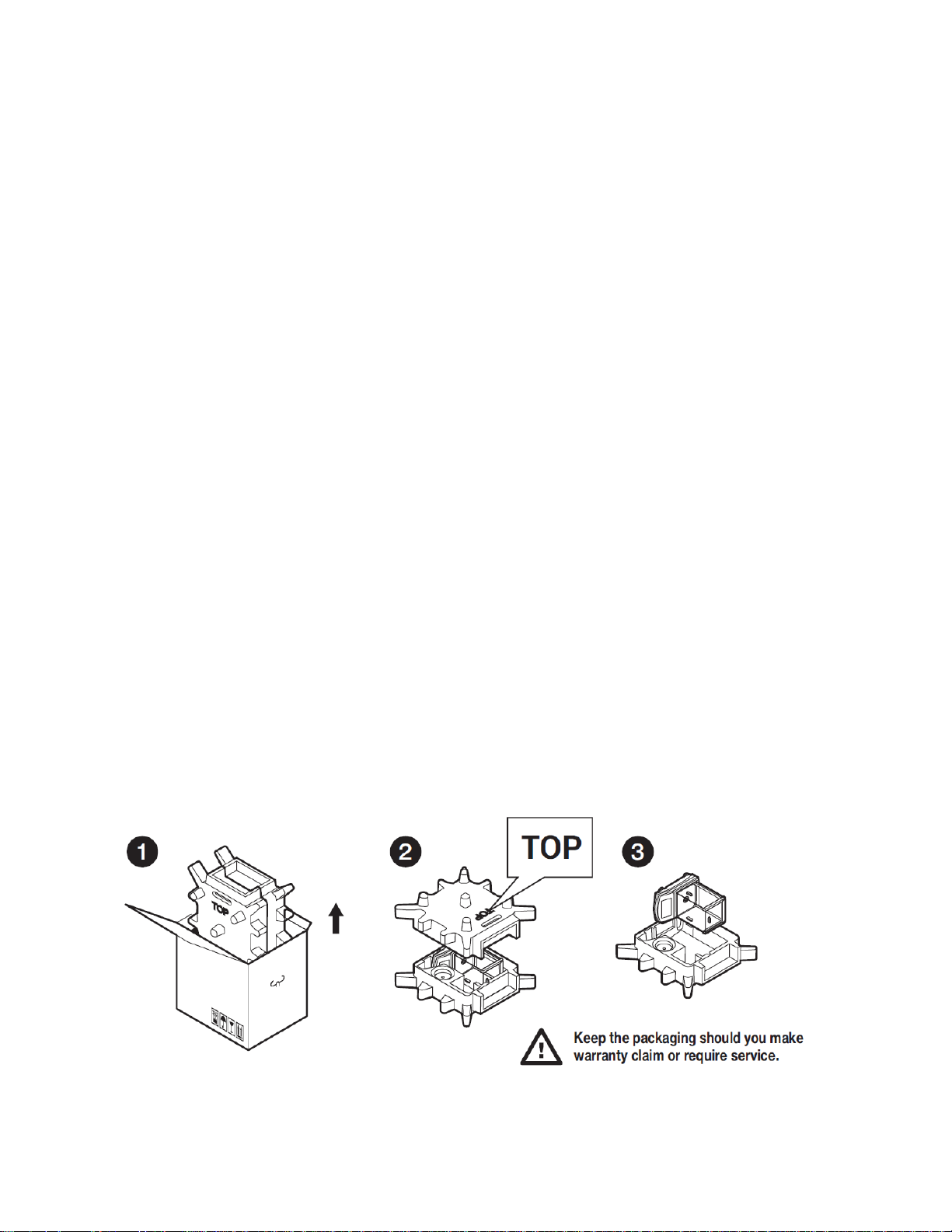
2.3 UNPACKING
To unpack the system, follow the diagram below-
7
Page 8
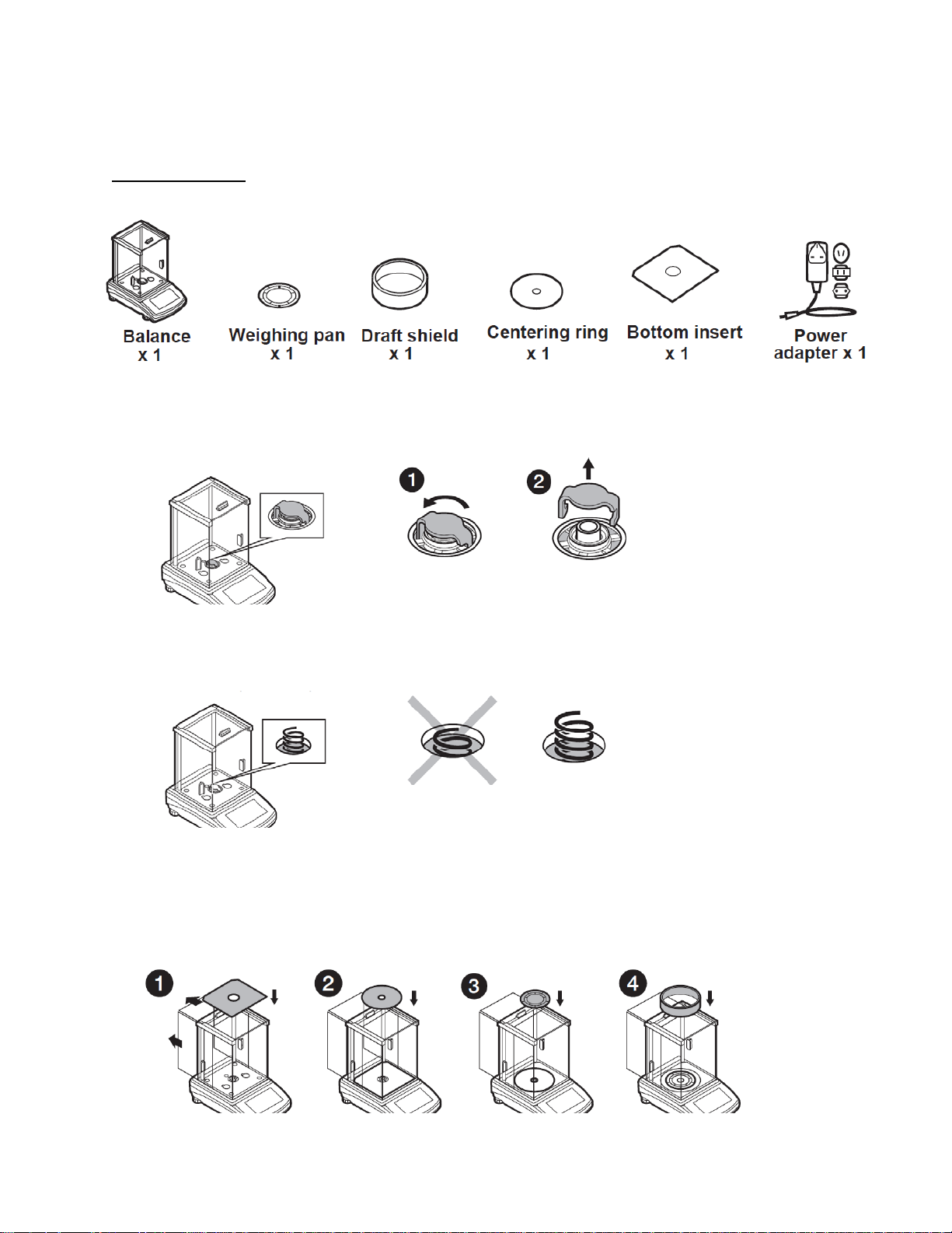
2.4 BALANCE ASSEMBLY
Model: LA-225.C
Components:
Installation:
1) Remove the transport lock– gently press the transport lock and turn it accordingly to
<OPEN>, keep the transport lock should your balance be transported in the future.
2) Check grounding spring to insure it is in the appropriate location. Make sure that the grounding
spring juts slightly out of the hole.
3) Install components following diagram below:
i. Bottom insert
ii. Centering ring [embossment side up]
iii. Weighing pan
iv. Draft shield
8
Page 9
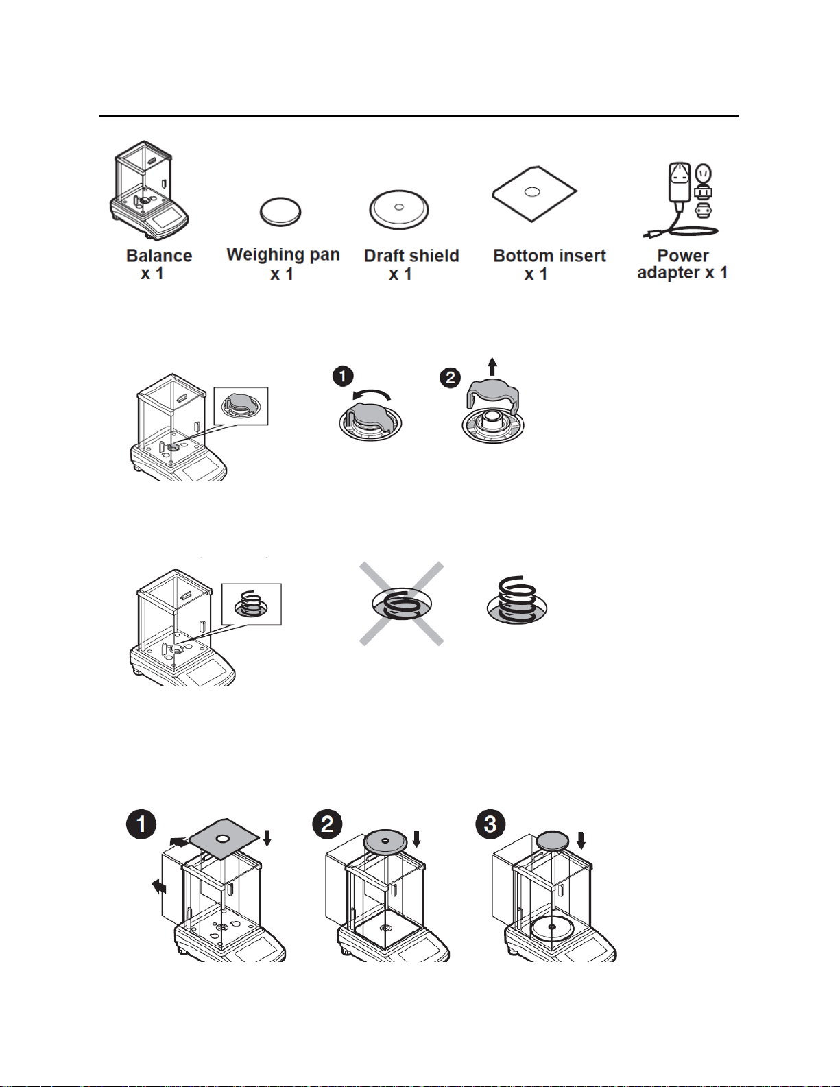
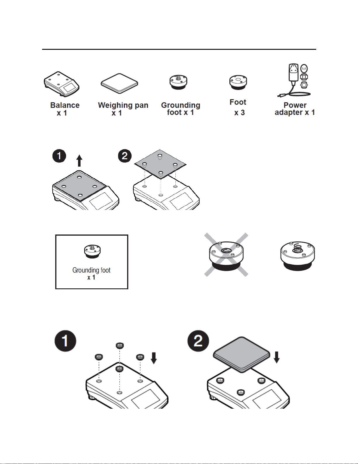
Model: LA-164.C, LA-224.C, LA-314.C, LA-64, LA-164, LA-224, LA-314, LA-314.N, LA-224.N
Componets:
Installation:
1) Remove the transport lock– gently press the transport lock and turn it accordingly to
<OPEN>, keep the transport lock should your balance be transported in the future.
2) Check grounding spring to insure it is in the appropriate location. Make sure that the grounding
spring juts slightly out of the hole.
3) Install components following the diagram below:
i. Bottom insert
ii. Centering ring [embossment side up]
iii. Weighing pan
9
Page 10
Model: LT-363.C, LT-603.C, LT-363, LT-603, LT-363.N, LT-1003.N
Components:
Installation:
1) Remove transport lock, keep the transport lock should your balance be transported in the future.
2) Check that the grounding spring is in the correct location, the spring juts slightly out of the hole.
3) Install components following the diagram below:
i. Rubber feet (grounding foot can be in any location on the balance)
ii. Weighing pan
iii. Glass draft shield
10
Page 11
Model: LT-1202.C, LT-2102.C, LT-4502.C, LT-1202, LT-2102, LT-4502, LT-1201.N, LT-4502.N
Components:
Installation:
1) Remove transport lock, keep the transport lock should your balance be transported in the future.
2) Check that the grounding spring is in the correct location, the spring juts slightly out of the hole.
3) Install components following the diagram below:
i. Rubber feet (grounding foot can be in any location on the balance)
ii. Weighing pan
11
Page 12
Model: LT-6002.C, LT-6002
Components:
Installation:
1) Remove transport lock, keep the transport lock should your balance be transported in the future.
2) Check that the grounding spring is in the correct location, the spring juts slightly out of the hole.
3) Install components following the diagram below:
i. Draft shield
ii. Rubber feet (grounding foot can be in any location on the balance)
iii. Weighing pan
12
Page 13
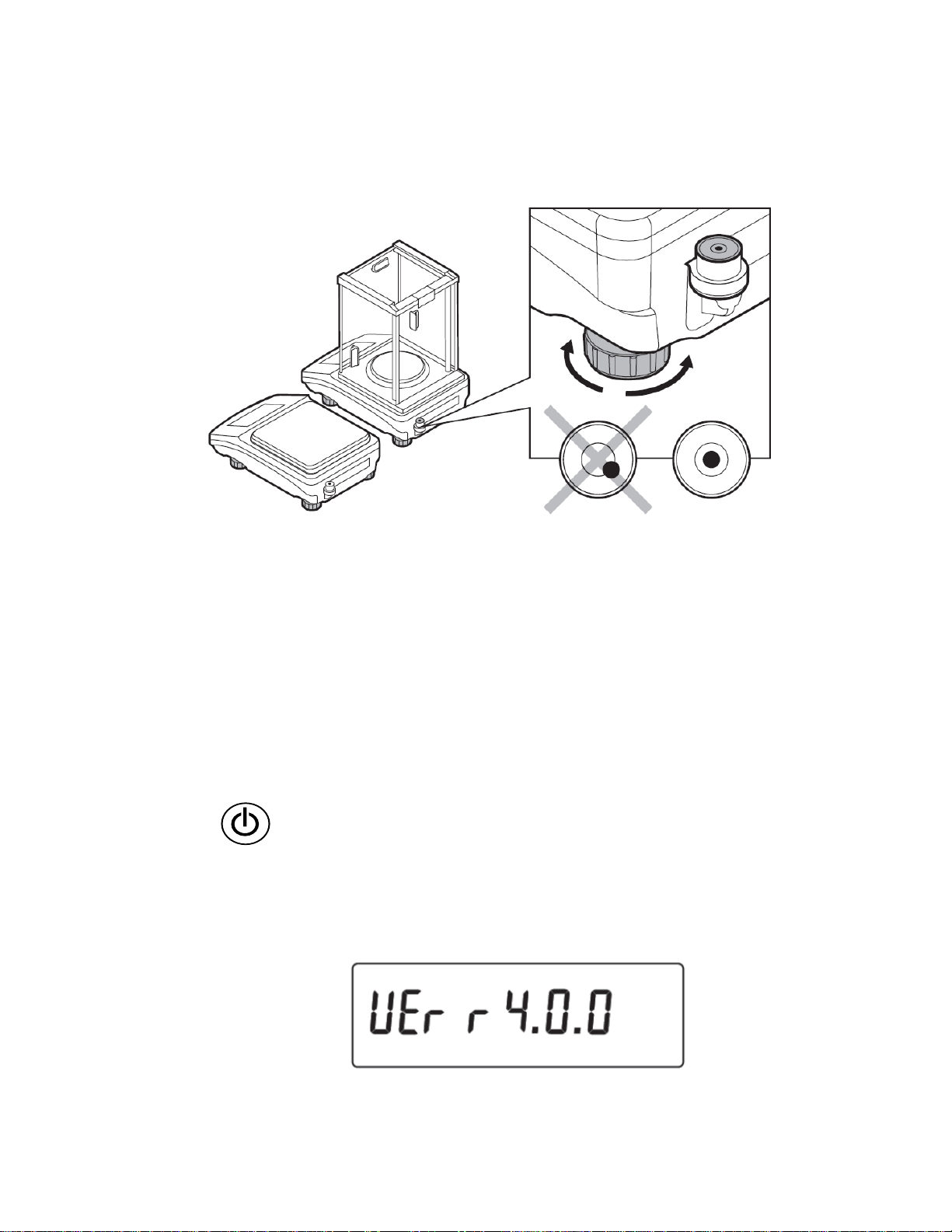
2.5 BALANCE LEVELING
It is necessary to level the balance prior to plugging it in. To level the balance, turn its feet until the
air bubble is in the center position.
The balance should firmly rest on a surface, each of the feet must be supported.
2.6 POWERING THE DEVICE
Before plugging in your balance, it is imperative to wait until the balance reaches thermal
stabilization.
For balances that were stored in much lower temperatures (e.g. during winter period), thermal
stabilization period will take at least 4 hours for Precision balances, and 8 hours for Analytical
balances.
• Balance should be plugged in only with the power adapter that comes standard with the
model. Nominal power supply of the power adapter (specified on the power adapter data
plate) should be compatible to the power supply.
• Plug the balance in – connect the power adapter to the socket, next connect its connector to
port located at the back of the balance housing.
• Press button located in the top right hand corner of the key pad.
! Remember to start the balance with no load on the weighing pan
• Test of the display unit takes place right after connecting the balance to the power, all the
elements and pictograms are backlit for a short time.
• Next, the name and the program number appears (please note, program number may be
different than what appears below)
13
Page 14
• the indication gets to ZERO (displayed reading unit depends on the balance). During the
Press to switch the balance ON/OFF. If switched off, balance
balance start, the test of an internal mass adjustment mechanism occurs (single location
and elevation of the internal mass adjustment).
• If the indication is different than zero, please press button
2.7 AMBIENT CONDITIONS STATE INDICATION (ANAL YTICAL BALAN CES )
The function is intended to inform on unstable ambient conditions for a balance, it is enabled only
for Analytical balances.
The function controls dynamic temperature changes occurring in the balance during its operation. If
the variation is greater than set limit values (temperature changes speed), then a blinking
thermometer pictogram is displayed on the screen.
The blinking thermometer pictogram means that temperature inside the balance is not stable, this
may result in inaccurate mass measurement. For such a case it is recommended to wait until the
temperature stabilizes or to perform balance adjustment (blanking of the blinking thermometer
pictogram).
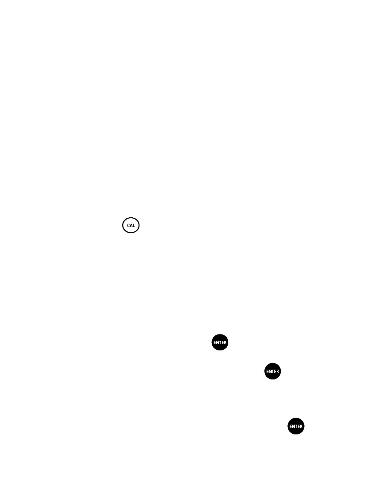
3. BALANCE CONTROL
3.1 BALANCE KEYBOARD
components other than the display are powered, and balance is in
stand-by mode.
Press to access data stored in a database: user, product, tare.
F10 button of the computer keyboard.
14
Page 15
Press to enter directly the active working mode settings.
PRINT/ENTER button
P1 CALIBRATION
[external adjustment]-
-Not available in .N verified model
[user adjustment]
-Not available in .N verified model
[automatic adjustment]
-Not available in .N verified model
F11 button of the computer keyboard.
Press to select working mode.
F5 button of the computer keyboard.
Press to change measuring units.
Press to send measurement to a printer or a computer (PRINT).
Press to confirm selected parameter value or function (ENTER).
Press to Zero the balance
Press to Tare the balance
Press to start adjustment / calibration process immediately.
F6 button of the computer keyboard.
Press to enter the main menu of a balance.
F7 button of the computer keyboard.
Press to operate balance menu or change parameter value
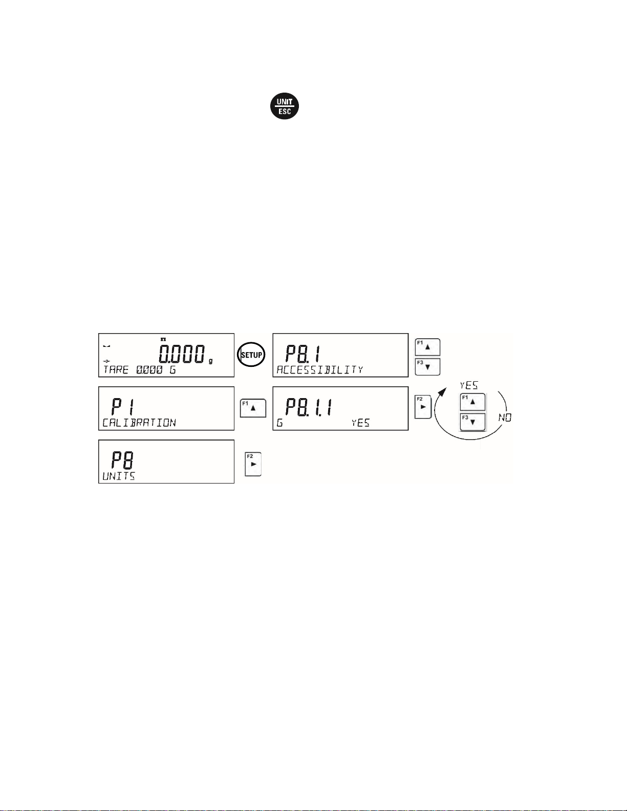
3.2 ENTERING BALANCE MENU
Operation of the balance menu is intuitive and easy to use. To enter balance menu, press
button.
The menu is divided into 9 basic function groups. Each group has an individual name starting with a
capital letter P.
P1.1
P1.2
P1.3
INT. CALIB.
EXT. CALIB.
USER CALIBRATION
P1.4 CALIBRATION TEST | [adjustment test]
P1.5
AUTO. CALIB.
|
[internal adjustment]
|
|
|
15
Page 16

P1.6
[time of automatic adjustment]
-Not available in .N verified model
P2 WORKING MODES
while working with the balance]
mass of the standard]
P3 COMMUNICATION
P3.1
COM1
|
[transmission parameters port COM 1]
P3.2
COM2
|
[transmission parameters port COM 2]
P4 DEVICES
P4.1
COMPUTER
|
[PC connection port]
P4.2
PRINTER
|
[printer connection port]
P4.3
BARCODE READER
|
[barcode connection port]
P4.4
ADD.DISPLAY
|
[additional display port]
P5 PRINTOUT
P5.1
CAL. REPORT
|
[contents of the adjustment report]
P5.2
HEADER
|
[contents of the header printout]
P5.3
GLP PRNT.
|
[contents of the weighing result prnt.]
P5.4
FOOTER
|
[contents of the footer printout]
P5.5
NSD.PRN.1
|
[project of non-standard printout 1]
P5.6
NSD.PRN.2
|
[project of non-standard printout 2]
P5.7
NSD.PRN.3
|
[project of non-standard printout 3]
P5.8
NSD.PRN.4
|
[project of non-standard printout 4]
P5.9
VARIABLE1
|
[project of variable 1]
AUTO. CALIB. C.
|
P2.1
P2.2
P2.3
P2.4
P2.5
P2.6
P2.7
P2.8
P2.9
P2.10
P2.11
P2.12
P2.13
P2.15
ACCESSIBILITY
WEIGHING
COUNTING PCS
CHECKWEIGHING
DOSING
DEVIATIONS
DENS. OF SOLIDS
DENS OF LIQUIDS
ANIMAL WEIGHING
STATISTICS
TOTALISING
PEAK HOLD
PIPETTES CALIB.
ADDING
|
|
|
|
|
|
|
|
|
|
|
|
|
|
[settings for the accessibility of individual modes
[setting for the function weighing]
[settings for the function counting pieces]
[settings for the function checkweighing]
[settings for the function dosing]
[settings for the function deviations % against the
[settings for determining density of solids]
[settings for determining density of liquids]
[settings for the function animal weighing]
[settings for the function statistics]
[settings for the function totalising]
[settings for the function peak hold]
[settings for the function pipettes calibration]
[settings for the function adding]
P4.5
P5.10
P5.11
EXT.BUTTONS
VARIABLE2
SEPERATOR DOT
|
|
|
[project of variable 2]
16
Page 17

P6 OTHER
P6.1 LANGUAGE | [menu language]
P6.2
ACCESS LEV.
|
[access levels for editing menu]
P6.4
BACKLIGHT
|
[display backlight level]
P6.6
AUTO SWITCH-OFF
|
[display turn-off time interval]
P6.7
DATE
|
[date settings]
P6.8
TIME
|
[time settings]
P6.9
DATE FORM.
|
[date format]
P7 INFO
P8 UNITS
operation]
P9 IMPORT/EXPORT (parameter displayed upon inserting the USB flash drive to the balance)
IE1
EXPORT
|
[data export]
IE2
IMPORT
|
[data import]
P6.3
P6.5
P6.10
P6.11
P7.1
P7.2
P7.3
P7.4
P7.5
P7.6
KEY SOUND
STAND-BY MODE
TIME FORM.
GLP AUTOTEST
BALANCE ID
SCALE TYPE
SOFT.VER.
ID PROD
TEMP.
SETUP PRNT.
|
|
|
|
|
|
|
|
|
|
[key sound]
[backlight turn-off time interval]
[time format]
[carrying out autotest for the balance]
P8.1 ACCESSIBILITY |
P8.2
P8.3
P8.4
START UNIT
USER UNIT U1
USER UNIT U2
CAUTION!
Balance memory modifications will be saved upon abandoning the menu (on return to weighing).
Press ESC button several times.
[declaration of units to be available for balance
|
|
|
[selection of a start unit, unit active on balance
start- up]
[parameter defining user’s unit 1]
[parameter defining user’s unit 2]
17
Page 18
4. WEIGHING MODE
Balance Menu: P2.2 WEIGHING
Load an object on the balance weighing pan. The stabilization of weighing result is indicated by a
stability marker visible on the left side of balance display, read the measurement result.
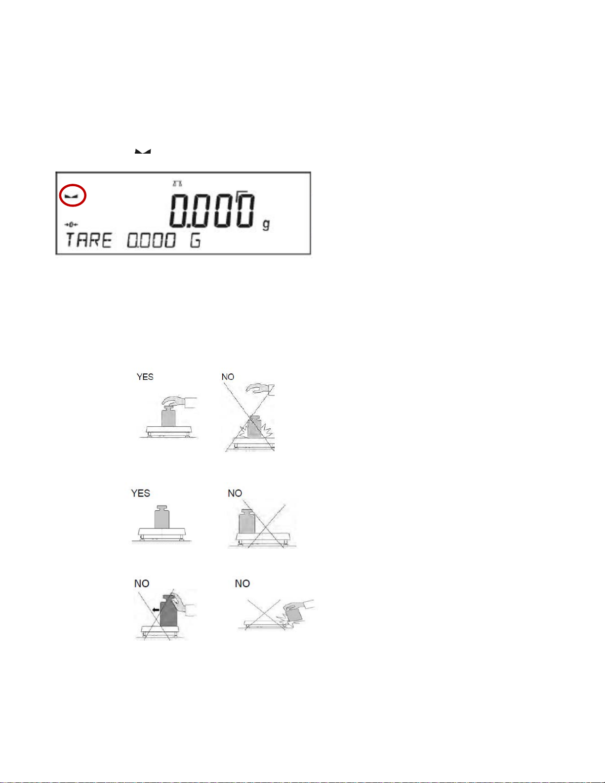
4.1 GOOD WEIGHING PRACTICE
To ensure long lasting use of a balance with correct and reliable measurements of weighed loads,
follow the suggestions below:
• Start the balance with no load on the weighing pan.
• Load the weighing pan carefully and avoid dropping it:
• Place weighed load in the center of the weighing pan:
• Avoid side loading, in particular side shocks:
18
Page 19
4.2 WEIGHING UNITS
To change the weighing unit, press the button. By pressing this button it changes the unit of
measure and will be in use from the moment of its activation until its changed or the balance is
switched off and on.
• For LA.N/LT.N model balances, you can select from the following units: [g], [mg] or [kg],
[ct]
• For LA.C/LT.C and LA/LT model balances, you can select from the following units: [g],
[mg], [kg], [ct], [lb], [oz], [ozt], [dwt], [tlh], [tls], [tlt], [tlc], [mom], [gr], [ti], [N]
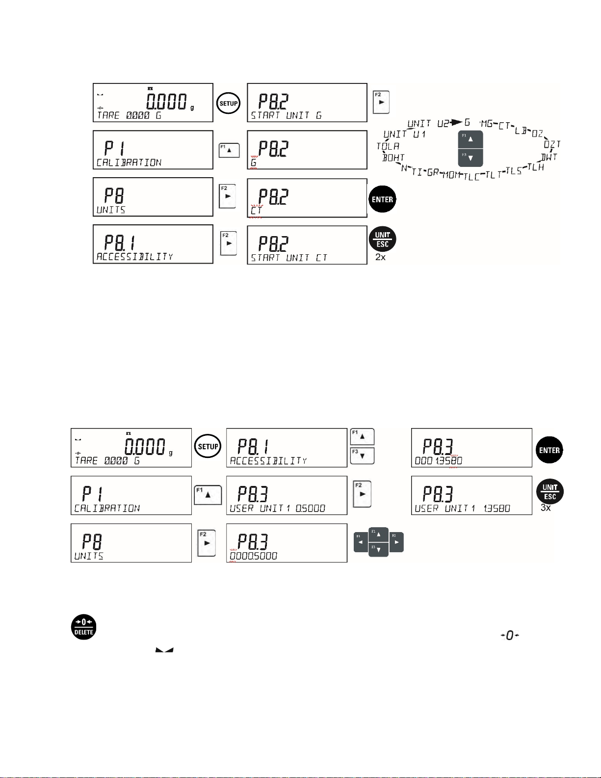
4.3 UNITS ACCESSIBILITY Balance Menu: P8.1 ACCESSIBILITY
The user may declare units to be available for use. Units with parameter value set to <YES> are
available for selection in specified operating modes.
Procedure:
4.4 START UNIT SELECTION Balance Menu: P8.2 START UNIT
Upon selection of start unit, the balance activates with the specified unit for these modes where
change of the unit is possible.
19
Page 20
Procedure:
4.5 USER-DEFINED UNIT Balance Menu: P8.3 USER UNIT U1
P8.4 USER UNIT U2
You may create two custom user-defined units. Displayed value of a user-defined unit is a
multiplication of measured mass value and a coefficient specified for the user-defined unit. The units
can be freely named with use of 3 characters’ maximum.
By default, the names are displayed as <u1> – user unit 1 and <u2> – user unit 2.
Procedure-
4.6 BALANCE ZEROING
Zeroing is a function allowing to zero the mass on the indication. To perform this function, press
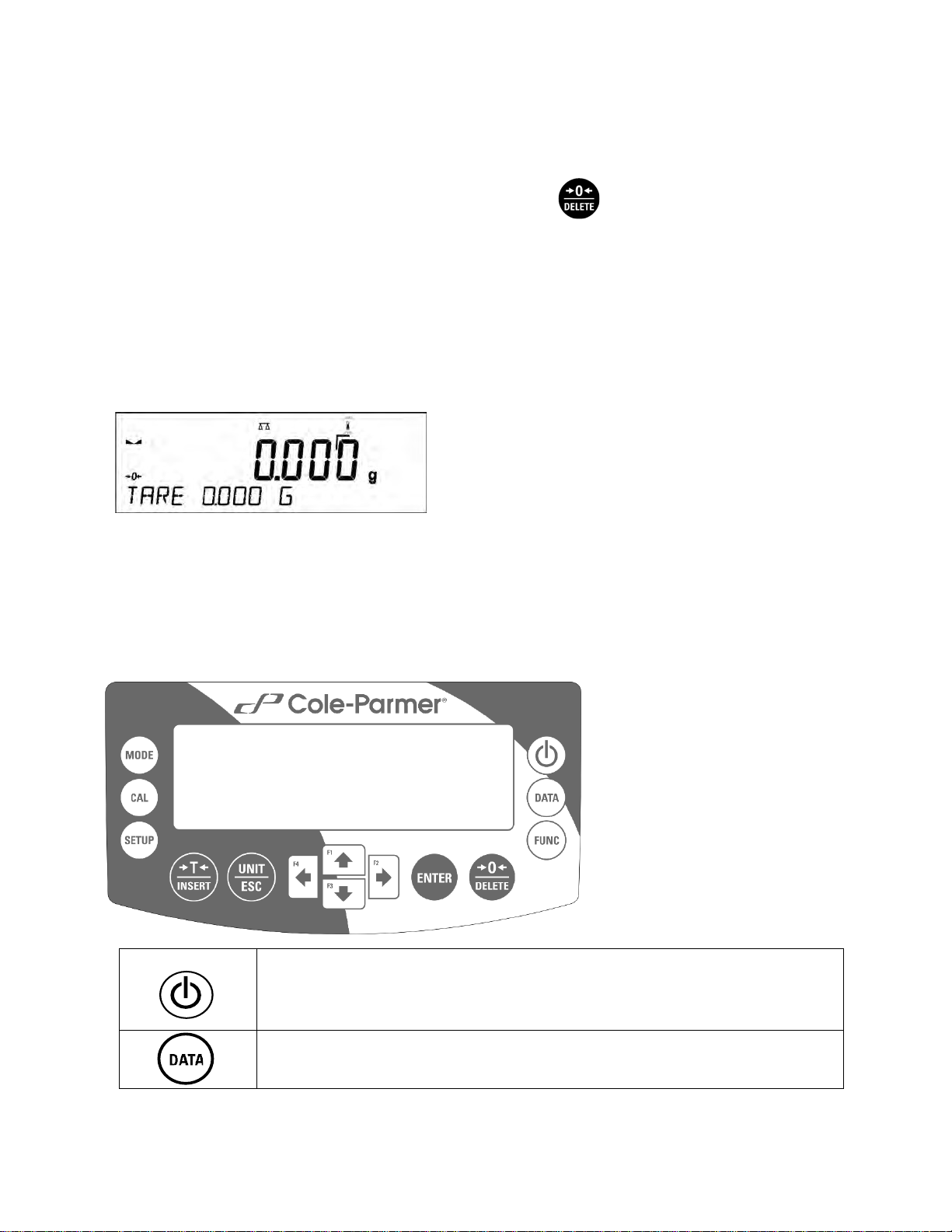
button. Mass indication of zero value shall be displayed together with precise zero and
stability markers .
The zeroing process is an equivalent for determining new zero point, recognized by the balance as
precise zero. Zeroing is possible only for stable status of display indication.
20
Page 21

! CAUTION
Zeroing the display indication is possible only within ±2% range of instrument’s maximum
capacity. If the zeroed value is above ±2% of the maximum capacity, then the balance
indicates a respective error message.
4.7 BALANCE TARING
Taring is a function allowing to determine net weight of a measured object. To determine the net
weight of the object, place object’s container (packaging) on the weighing pan, and on stabilization
of measurement result press key. The display indicates mass equaling zero and symbols:
Net and . On taking off the weighed load and its packaging from the weighing pan, the display
indicates sum of total tared mass with a minus sign.
The balance allows the user tare value to a database-stored product. Using this option, the software
automatically uploads data on tare value for a particular product upon its selection from the
database.
! CAUTION
Taring negative values is impossible. On taring negative values the balance responds with
an error message, Err3. In such case, zero balance indication and repeat taring procedure.
4.7.1 MANUAL TARE DETE RMINATION
This option allows for the setting of a tare value through a manual input of the value.
Procedure-
• Press quick access key F2, to which <ENTER TARE> option has been assigned.
• Wait for a respective window to open.
• Use the arrow buttons to enter the tare value and press button,
• The balance returns to the weighing mode, and the display indicates entered tare value
with minus “–" sign.
4.7.2 DELETING TARE
Entered tare value can be deleted by pressing button or by entering tare value of 0.000g
(see description above).
4.7.3 TARE DATABASE
Tare values commonly utilized by user can be saved within the Tare Database.
Procedure:
• Press quick access key F4, to which <SELECT TARE> option has been assigned or
click <SELECT TARE> option available upon pressing button.
• Wait for the first packaging weight, recorded in tare database, to be displayed.
21
Page 22

• Use the arrow buttons to select the tare which is to be recalled and press button,
• The balance returns to the weighing mode, and the display indicates entered tare value
with a minus “–" sign.
OR
• While in any working mode, press button.
• Enter b3 <TARE> option.
• Wait for the first packaging weight, recorded in tare database, to be displayed.
• Use the arrow buttons to select the tare which is to be recalled and press button.
• The balance returns to the weighing mode, and the display indicates entered tare value
with a minus “–" sign.
4.7.4 AUTOTARE
Autotare is used for quick determination of net weight for loads with different tare values,
wherein they are measured one after another.
When the function is act i ve (<AUTOTARE> parameter set to <YES> opt ion), the operating
process takes the following steps.
Procedure-
• Make sure that the weighing pan is empty and press button responsible for zeroing.
• Put product packaging on a weighing pan.
• After measurement stabilization, automatic taring of the packaging mass takes place
(Net marker then appears in the upper part of the display).
• Place product to be weighed into the packaging.
• The display shows net weight of the product.
• Remove the product together with the packaging from the weigh pan.
• The balance removes the tare value (packaging weight recorded during the first step of
the operating process) after the gross weight value (set in <AUTO THRES> parameter)
has been exceeded.
• Place packaging of the next product on the weighing pan, automatic taring of the
packaging weight proceeds after measurement stabilization (Net m arker appears in the
top section of the display);
• Place next product that is to be packed.
For correct operation of the balance with AUTOTARE function, it is necessary to adjust the
threshold value.
<AUTO THRES> parameter is connected with the following functions:
• automatic tare
• automatic operation
No automatic taring takes place as long as the gross weight value stays within the range set in
<AUTO THRES> parameter.
22
Page 23

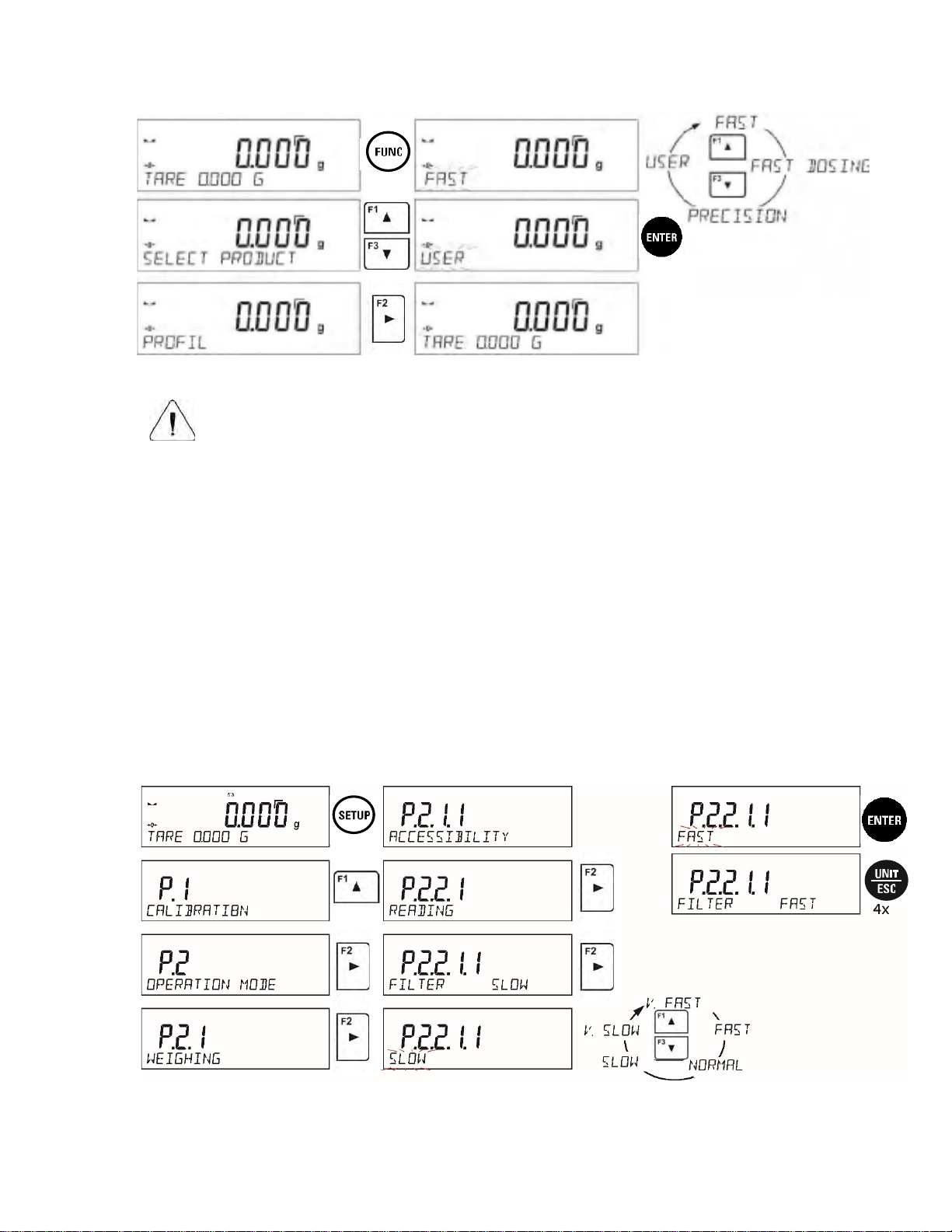
4.8 WEIGH MODE SETTINGS
The software allows setup of operating parameters (filters, value release and autozero function,
deleting the last digit and other settings) separately for each working mode. Only for User profile
you can modify all settings. For other profiles (Fast, Fast dosing, Precision) Filter and Value
release parameters are default and cannot be modified.
It enables customizing the instrument and utilizing its properties depending on your needs and
expectations, or on specific requirements for selected working mode (e.g. DOSING); as a result the
device operation is quick and easy.
To simplify weighing instrument operation, there are 4 profiles in the software. The profiles are
selected and saved so that the weighings for respective requirements and conditions are optimized.
Profile settings apply to settings for specific working mode and are grouped in the following
parameter: Setup/Working modes/Weighing/Readout. For detailed description of these settings go
to the next section of this user manual.
These are the following profiles:
• User – the basic profile for which filter settings are selected in a way enabling fast and
precise weighing.
• Fast – profile enabling weighing of any mass regardless of the working mode. When running
the balance for the first time, this profile is started automatically. For this profile the
parameters are selected in a way enabling obtaining the measurement result as fast as it is
possible,
• Fast dosing – the profile is dedicated for fast dosing.
• Precision – the profile is dedicated for precise dosing of any mass regardless of the
working mode. For this profile the weighing process takes the most time, but the result is the
most accurate and precise,
Caution: You can modify all settings of User profile. Settings of other profiles (Fast, Fast dosing and
Precision) can be modified only to a limited extend.
Name of currently selected profile is displayed in the bottom line. The profile can be selected
individually for working mode. The balance saves the last used profile in each working mode (with
your modifications) and starts operation with that profile selected.
Procedure:
• Select <PROFILE> option upon pressing key.
• Using navigating keys, select profile and press key.
• The balance returns to weighing mode and operates in accordance with set profile.
23
Page 24
UTION!
CA
The higher filter level, the longer the weighing time.
4.8.1 FILTER LEVEL SETTING
Filter level setting (function unavailable for the following profiles: Fast, Fast dosing,
Precision)
Fi
lter settings adjustment depends on the working environment. For the best possible conditions
the filter can work in a very fast mode (V.FAST value for Filter parameter); however, if the
conditions are poor (shakes, drafts), the filter should be set to slow or very slow option (SLOW
or V. SLOW value for Filter parameter). The effectiveness of the filter is different throughout the
weighing range. The filter works slower when “approaching” the weighed mass, it works more
intensively for weighed mass within the set range of the filter (the parameter for setting filter
range is accessible only from the service menu – the user does not have any access to it).
D
epending on the filter, the weighing time is shorter (V.FAST and FAST) or longer (SLOW and
V. SLOW).
24
Page 25
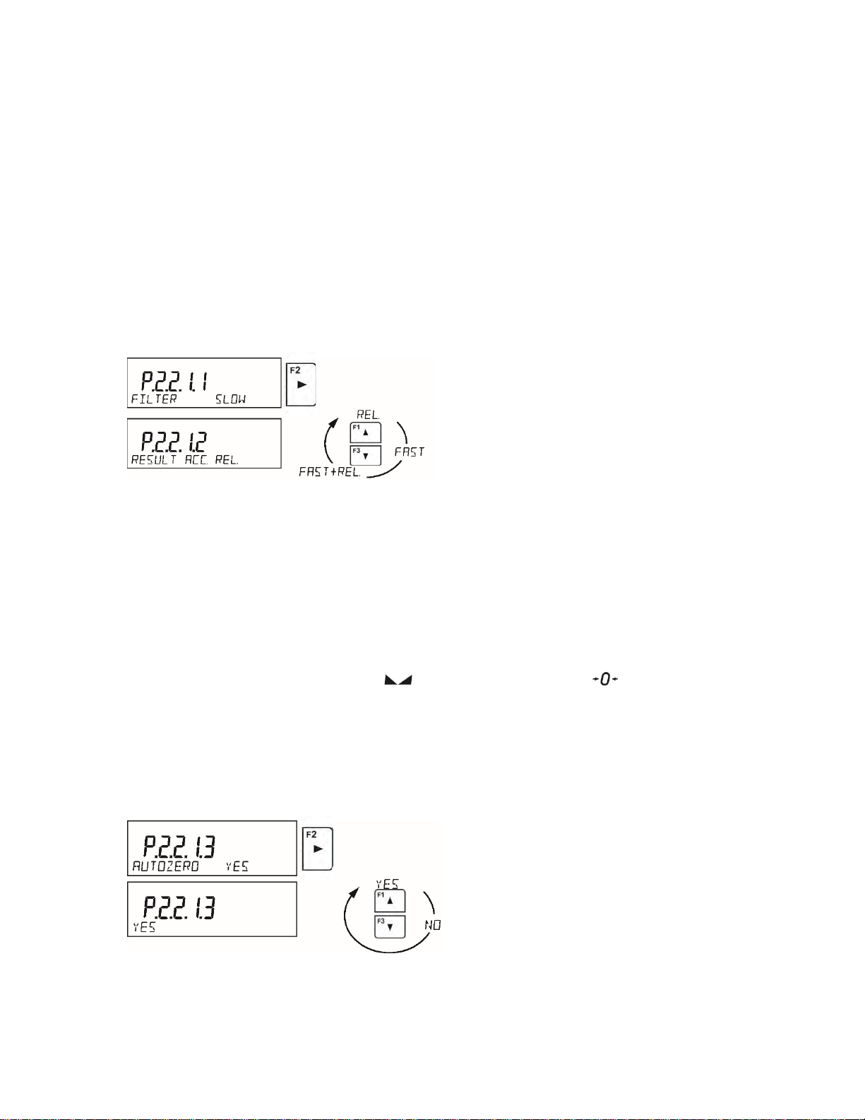
4.8.2 VALUE RELEASE
alance Menu: P2.2.1.2 RESULT ACC
B
V
alue release setting (function unavailable for the following profiles: Fast, Fast dosing,
Precision)
S
ince ambient conditions at a workplace vary, it is necessary to determine the value release
parameter that are best for your working environment, parameter options are: <FAST.+REL.>,
<FAST> or <RELIABLE>. Depending on the selected option, weighing time is either shorter or
longer.
Procedure-
4.8.3 AUTOZERO FUNCTION
alance Menu: P2.2.1.3 AUTOZERO
B
T
he balance features an autozero function (Auto). This function automatically controls and
corrects the zero reading. When Autozero is enabled, it compares balance readings at declared
time interval e.g. 1s, if weighing pan is unloaded and display indication is close to zero. If results
vary less than declared AUTOZERO range e.g. one division, balance zeroes automatically,
marker of stable measurement result , and precise zero marker are displayed.
If AUTOZERO function is enabled, then each weighing process starts from precise zero point.
There are, however, some instances when this function can be a disturbing factor for the
measuring process; e.g. very slow placing of a load on the weighing pan (load adding). Here,
zero reading correction can also correct the actual reading of loaded mass.
Procedure:
25
Page 26
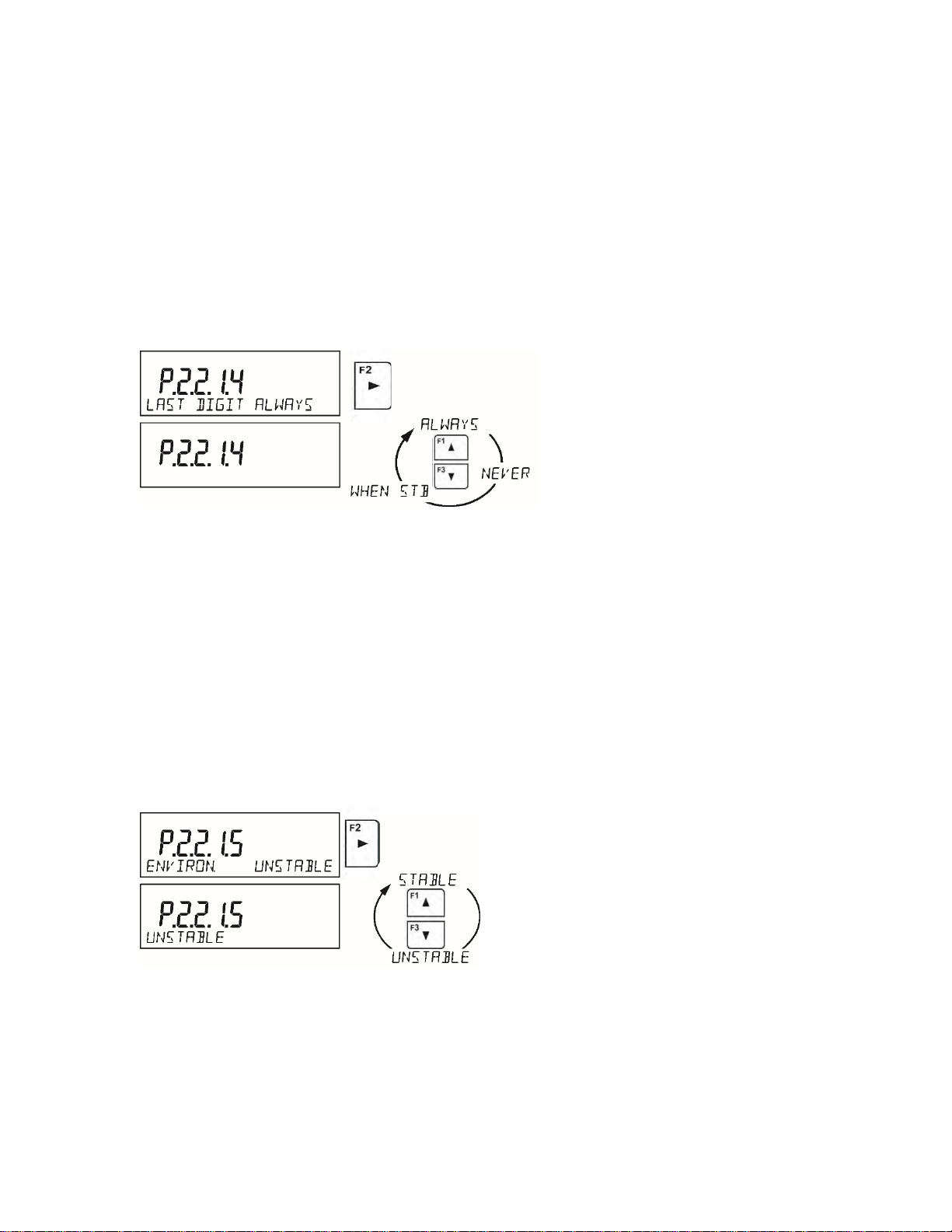
4.8.4 LAST DIGIT DISPLAY
alance Menu: P2.2.1.4 LAST DIGIT
B
Func
tion enables displaying the last digit of decimal place for a weighing result. There are three
available options:
• <ALWAYS> all digits visible
• <NEVER> last digit is not displayed
• <WHEN STB> last digit is displayed only for a stable weighing result
rocedure:
P
4.8.5 BALANCE AMBIENT CONDTIONS
alance Menu: P2.2.1.5 ENVTRON
B
arameter relating to ambient and environmental conditions in which the balance operates.
P
here are two options: <STABLE> and <UNSTABLE>.
T
• Selecting <STABLE> mode makes the balance work much faster, i.e. weighing takes
much less time than for <UNSTABLE> mode.
• If the ambient conditions are unstable it is recommended to use UNSTABLE mode. By
default, the parameter is set to <STABLE> option.
rocedure:
P
26
Page 27

5. CALIBRATION (LA.C & LT.C SERIES)
alance Menu: P1 CALIBRATION
B
T
o ensure the highest weighing accuracy, it is recommended to periodically introduce a corrective
factor of indications to balance memory, the said factor is referre d to as a mass standard.
alibration should be carried out:
C
• Before the beginning of weighing procedure
• If long breaks between following measuring series occur
• If temperature inside the balance changes more than: 1°C or 2°C for Analytical balances or 2°C
for Precision series balances.
Types of calibration:
• Internal calibration (automatic or manual)
• External calibration
• User-defined calibrati
UTION!
CA
Remember to carry out the calibration process when there is no load on the pan! When the
weighing pan is loaded, command <RANGE EXCEEDED> is displayed. In such a case
remove the load and restart the adjustment process. Adjustment process can be aborted if
necessary by pressing Esc button at any time during the process.
on
5.
1 INTERNAL CALIBRATION
The internal calibration process can be initiated automatically and manually.
Manual calibration is when the internal calibration procedure is triggered by pressing button.
Automatic calibration is carried out automatically by the balance and informs the user the process is
going to start.
5.1.1 AUTOMATIC INTERNAL CALIBRATION
alance Menu: P1.1 INT. CALIB.
B
T
he automatic calibration process can take place in the following instances:
alance Menu: P1.6 AUT. CALIB.
B
• <NONE> automatic calibration disabled
• <TIME> calibration takes place in time intervals. The time interval is declared in hours
and ranges between 0.5 and 12 hours.
• <TEMP> calibration is triggered by temperature change only. At each calibration
ocess, the temperature is recorded. The next calibration is automatically initiated if
pr
temperature changes more than 1°C or 2°C from the last saved temperature.
• <BOTH> calibration is triggered by both, temperature changes and time.
27
Page 28
Procedure:
• The balance detects the necessity of carrying out a calibration and signals it by
displaying a thermometer or clock pictogram and <Cal> sign at the top of the display
• Once the balance signals the need for a calibration, a 2-minute long time interval takes
place allowing the weighing procedure to be completed
• Once the 2-minute long time elapses, the balance display shows the message CAL_30
tarts counting down from 30..29..28 to 0 (indicated value is the counter)
and s
• The balance user has 30 seconds to make a decision
• To allow the internal calibration, do not take any actions
• If more time is needed to complete weighing procedure, press Esc.
When pressed, the balance returns to weighing procedure and displays last
weighing result.
In about 5 minutes balance indicates CAL_30 message again.
• The calibration process can be postponed multiple times, however, postponing the
alibration for a long time can lead to larger errors in the weighing process. The errors
c
can be the result of temperature changes and as a consequence changes of balanc
s
ensitivity.
5.1.2 MANUAL INTERNAL CALIBRATION
Manual triggering of the internal calibration procedure can take place in two ways. First,
e
through the pressing button. Second, is through the balance menu P1.1 INT. CALIB.
5.2 EXTERNAL CALIBRATION
B
alance Menu: P1.2 EXT. CALIB.
E
xternal calibration is carried out by means of an external mass standard of specified accuracy
class and weight. Both, accuracy class and mass standard weight depend on balance type and max
capacity and the correct value is saved within the balances factory settings. The process takes
semi-automatic form; successive stages are signaled with prompts.
rocedure:
P
• Go to balance menu P1.2 EXT. CALIB. , press button
• The balance displays a prompt to unload the weighing pan, <UNLOAD PAN> (the weighi
pan m
ust be empty). When the weighing pan is unloaded, press button.
• The balance determines mass of an empty pan, message <CALIBRATION> is displayed i
ng
n
the bottom line.
• Next, the message <LOAD WEIGHT> appears and the mass value to be placed on th
w
eighing pan is displayed, e.g. 200.000g (depending on the type of balance).
e
• Place the external calibration weight of displayed mass value and press button. The
balance determines the mass, message <CALIBRATION> is displayed in the bottom line.
28
Page 29

5.3 USER CALIBRATION B
alance Menu: P1.3 USER CALIB.
An external calibration process can be carried out with an external mass standard of defined value
by the user. The calibration mass must be at a value greater than 30% of the balances Max range
Procedure:
• Run a user calibration process, the first step of the process is to declare the mass of a weight
that is to be used for calibration. The mass must be > 30% Max capacity. Utilize the arrows
to enter the weight mass.
• Once the mass of the weight is entered and confirmed, the message prompting the user to
remove the weight from the pan is displayed: <UNLO AD P AN > (the weighing pan must be
empty).
• Unload the pan and press button.
• The balance determines the weight of an unloaded pan, message <CALIBRATION> is
shown in the bottom line. Next, message <LOAD WEIGHT> and mass value to be plac
on the weighing pan are displayed, e.g. 200.000g (depending on the type of balance).
• Place an external adjustment weight of displayed mass value and press button. The
balance determines the mass, message <CALIBRATION> is displayed in the bottom line.
ed
.4 ADJUS TM EN T TEST
5
B
alance Menu: P1.4 CALIB. TEST
T
he Adjustment Test function enables comparing the result of an internal automatic adjustment with
the value recorded in balance factory parameters. The comparison is used for determining balance
sensitivity drift over time.
6. CALIBRATION (LA & LT SERI E S )
B
alance Menu: P1 CALIBRATION
To
ensure the highest weighing accuracy, it is recommended to periodically introduce a corrective
factor of indications to balance memory, the said factor is referre d to as a mass standard.
Calibration should be carried out:
• Before the beginning of weighing procedure
• If long breaks between following measuring series occur
• If temperature inside the balance changes more than: 1°C or 2°C for Analytical balances or 2°C
for Precision series balances.
Types of calibration:
• External calibration
• User-defined calibrati
on
29
Page 30

CAUTION!
Remember to carry out the calibration process when there is no load on the pan! When the
weighing pan is loaded, command <RANGE EXCEEDED> is displayed. In such a case
remove the load and restart the adjustment process. Adjustment process can be aborted if
necessary by pressing Esc button at any time during the process.
6.1 EXTERNAL CALIBRATION
Balance Menu: P1.1 EXT. CALIB.
External calibration is carried out by means of an external mass standard of specified accuracy
class and weight. Both, accuracy class and mass standard weight depend on balance type and max
capacity and the correct value is saved within the balances factory settings. The process takes
semi-automatic form; successive stages are signaled with prompts.
Procedure:
Go to balance menu P1.1 EXT. CALIB. , press button
• The balance displays a prompt to unload the weighing pan, <UNLOAD PAN> (the weighing
pan must be empty). When the weighing pan is unloaded, press button.
• The balance determines mass of an empty pan, message <CALIBRATION> is displayed in
the bottom line.
• Next, the message <LOAD WEIGHT> appears and the mass value to be placed on the
weighing pan is displayed, e.g. 200.000g (depending on the type of balance).
• Place the external calibration weight of displayed mass value and press button. The
balance determines the mass, message <CALIBRATION> is displayed in the bottom line.
6.2 USER CALIBRATION Balance Menu: P1.2 USE R CALIB.
An external calibration process can be carried out with an external mass standard of defined value
by the user. The calibration mass must be at a value greater than 30% of the balances Max range
Procedure:
• Run a user calibration process, the first step of the process is to declare the mass of a weight
that is to be used for calibration. The mass must be > 30% Ma x capacity. Utilize the arrows
to enter the weight mass.
• Once the mass of the weight is entered and confirmed, the message prompting the user to
remove the weight from the pan is displayed: <UNLO AD P AN > (the weighing pan must be
empty).
• Unload the pan and press button.
30
Page 31

• The balance determines the weight of an unloaded pan, message <CALIBRATION> is
shown in the bottom line. Next, message <LOAD WEIGHT> and mass value to be placed
on the weighing pan are displayed, e.g. 200.000g (depending on the type of balance).
• Place an external adjustment weight of displayed mass value and press button. The
balance determines the mass, message <CALIBRATION> is displayed in the bottom line.
7. CALIBRATION (LA.N & LT.N SERIES)
Balance Menu: P1 CALIBRATION
To ensure the highest weighing accuracy, it is recommended to periodically introduce a corrective
factor of indications to balance memory, the said factor is referre d to as a mass standard.
Calibration should be carried out:
• Before the beginning of weighing procedure
• If long breaks between following measuring series occur
• If temperature inside the balance changes more than: 1°C or 2°C for Analytical balances or 2°C
for Precision series balances.
Types of calibration:
• Internal calibration (automatic or manual)
CAUTION!
Remember to carry out the calibration process when there is no load on the pan! When the
weighing pan is loaded, command <RANGE EXCEEDED> is displayed. In such a case
remove the load and restart the adjustment process. Adjustment process can be aborted if
necessary by pressing Esc button at any time during the process.
7.1 INTERNAL CALIBRATION
The internal calibration process can be initiated automatically and manually.
Manual calibration is when the internal calibration procedure is triggered by pressing button.
Automatic calibration is carried out automatically by the balance and informs the user the process is
going to start.
7.1.1 AUTOMATIC INTERNAL CALIBRATION
Balance Menu: P1.1 INT. CALIB.
The automatic calibration process can take place in the following instances:
• Adjustment on plugging the balance to the mains
• Adjustment triggered by temperature change inside the balance. The balance is
equipped with a very precise system for monitoring temperature. At each adjustment
31
Page 32

process, the temperature is recorded. The next adjustment is automatically initiated if
temperature changes more than 1°C or 2°C from the last saved temperature.
Procedure:
• The balance detects the necessity of carrying out a calibration and signals it by
displaying a thermometer and <Cal> sign at t he top of the display
• Once the balance signals the need for a calibration, a 2-minute long time interval takes
place allowing the weighing procedure to be completed
• Once the 2-minute long time elapses, the balance display shows the message CAL_30
and starts counting down from 30..29..28 to 0 (indicated value is the counter)
• The balance user has 30 seconds to make a decision
• To allow the internal calibration, do not take any actions
• If more time is needed to complete weighing procedure, press Esc.
When pressed, the balance returns to weighing procedure and displays last
weighing result.
In about 5 minutes balance indicates CAL_30 message again.
• The calibration process can be postponed multiple times, however, postponing the
calibration for a long time can lead to larger errors in the weighing process. The errors
can be the result of temperature changes and as a consequence changes of balance
sensitivity.
7.1.2 MANUAL INTERNAL CALIBRATION
Manual triggering of the internal calibration procedure can take place in two ways. First,
through the pressing button. Second, is through the balance menu P1.1 INT. CALIB.
7.2 ADJUSTM E NT TE S T
Balance Menu: P1.4 CALIB. TEST
The Adjustment Test function enables comparing the result of an internal automatic adjustment with
the value recorded in balance factory parameters. The comparison is used for determining balance
sensitivity drift over time.
32
Page 33

8. WORKING MODES- GENER AL INFORMATION
Weighing
balance measures gravitational force which attracts the load. An obtained result is
a form of measurement result. More
Parts Counting
information found in Section 10.
Dosing
Deviations % (Percent Weighing)
ratio of a sample in relation to a standard
Density of solids
Density of liquids
Animal Weighing
Statistics
Peak Hold
Totalising
The balance features the following working modes:
Means of operation: weight of a load is determined through an indirect measurement. A
processed to a digital format and displayed in
information found in Section 5.
Means of operation: based on a determined mass of a single part it is possible to count
another part, if the mass of the single part is determined with sufficient accuracy, and that
the following parts are equal in mass. More information found in Section 9.
Check Weighing
Means of operation: control of sample mass with applied thresholds. A user should
specify the value of min threshold <LO> and max threshold <HI>. More
Means of operation: a user should specify sample’s target mass to be obtained by
pouring. More information found in Section 11.
Means of operation: control of percent
(reference). Obtained data provides percent ratio on how test sample differs from the
accepted standard (reference). More information found in Section 1 2.
Means of operation: based on Archimedes principle, a balance determines density of
solids. The mode requires an optional density determination kit. More information
found in Section 13.
Means of operation: based on Archimedes principle, a balance determines density of
liquids. The mode requires an optional density determination kit. More information
found in Section 14.
Means of operation: mass measurement takes place with application of filters dampening
animal moves on a weighing pan, thus enabling obtaining a correct measurement result.
More information found in Section 15.
Means of operation: carried out measurements are used to calculate statistical data, such
as Min, Max, deviation, etc. More information found in Section 16.
Means of operation: max temporary indication occurring in course of the weighing
process is hold on a display. More information found in Section 17.
Means of operation: by mixing specified ingredients you can obtain particular mixture, in
order to program given formulation you have to specify weight of particular ingredients.
More information found in Section 18.
33
Page 34

Pipettes Calibration
Means of operation: applied to fixed volume pipettes and adjustable volume pipettes.
Section
Adding
Software determines accuracy and repeatability errors. More information found in
19.
Means of operation: allows you to add net masses of weighed samples.
Section 20.
8.1 RUNNING WORKING MODE
In order to run a particular mode press button, and select the mode from the list.
Procedure:
CAUTION!
Upon restart, the balance is launched with the most recently operated working mode. For
settings of this function read later sections of this user manual.
8.2 WORKING MODE ACCESSIBILITY
Balance Menu: P2.1 ACCESSIBILITY
User’s have the av ailability to declare which working modes are to be accessible. You can deactivate
working that are not used in course of balance operation, to do it, change the accessibility value to
<NO> for a particular parameter.
34
Page 35

Procedure:
9. PARTS COUNTING
Parts counting is a working mode which enables determination of quantity of small parts with equal
weight. Determined mass of a single part is used for the counting procedure.
9.1 SETTING REFERENCE MASS: MASS DETERMINATION FOR THE SAMPLE OF KNOWN
QUANTITY
While determining the mass of a single piece, ACAI function (Automatic Accuracy Correction) is in
use.
Means of operation of ACAI function:
• Number of pieces (on adding) on balance’s weighing pan has to be greater than before
• Number of pieces (on adding) on balance’s weighing pan must be less than twice the
amount displayed before adding parts
• Current quantity of parts must be within the ~ 0,3 tolerance of the total value
• Measurement result has to be stabilized.
Procedure:
• Place the container on the pan and tare its mass,
• Press F2 button to which the function <DETERMINE SAMPLE> is assigned, wait to see the
editing window <SAMPLE QUANTITY>
• Use arrow buttons or to select the correct sample quantity.
• For optional quantity variable (displayed value <0000>) enter any number using arrow buttons
• Confirm selected sample quantity, confirmation message - <PLACExx PCS> - shall be seen.
35
Page 36

• Place the declared number of pieces in the container and when the result is stable (the symbol
is displayed) confirm the mass by pressing button,
• The balance software automatically counts a single piece mass and enters the mode PARTS
COUNTING displaying the number of pieces which are on the pan (pcs). In the bottom line, a
single piece mass value is shown (if the option has been selected for <INFORMATION>
function).
CAUTION!
Remember that:
• The total mass of all the pieces put on the weighing pan must not be greater than
the balance maximum weighing range.
• The mass of a single piece cannot be lower than 0.1 reading unit of the balance. If
this condition is not met, the balance displays message: <Single part mass too
low>.
• While determining the number of pieces, wait for the stability pictogram , next
confirm the quantity.
• You can confirm the declared quantity by pressing button only after the stability
pictogram is displayed. Otherwise, the balance will not accept the measurement.
9.2 SETTING REFERENCE MASS: ENTERING MASS VALUE
With this option, you set the mass of a sample to be utilized for counting the various parts.
Procedure-
• Press F button to which the function <ENTER SAMPLE> is assigned, wait to see the editin g
window <ENTER SAMPLE>
• Use arrow buttons to enter the known weight value of a single piece.
36
Page 37

<Min>: mass lower than the value of the low threshold
• The balance automatically enters <PARTS COUNTING> mode displaying the number of
pieces which are on the pan (pcs). In the bottom line, a single piece mass value is shown (if
the option has been selected for <INFORMATION> function)
10. CHECKWEIGHING
Checkweighing is a working mode using two thresholds (LOW and HIGH) in order to check mass of the
samples. It is generally assumed that the mass is correct if it is contained within the threshold values.
Procedure:
• Press F button to which the function <ASSIGN THRESHOLDS> is assigned, the editing window
is displayed and the value of MIN low threshold can be ascribed. The ascribed value must be
given in a current unit.
• Use arrow buttons to enter low threshold value, press button to confirm.
• The software automatically proceeds to the editing window of MAX high threshold value, which
is to be given in the current unit. Use arrow buttons to enter high threshold value, press
button to confirm.
• The balance software proceeds to <CHECKWEIGHING> mode, values of declared thresholds
are displayed in the bottom line (if such an option has been selected for <INFORMATION>
function).
• At the top of the display the message <Min> is shown, it indicates weight value placed on the
weighing pan in relation to low limit weight value. Bottom line of the display, if <BARGRAPH>
option is enabled, shall demonstrate weight indication, in a graphic form, in relation to set
thresholds.
37
Page 38

<Ok>: mass contained within thresholds
<Max>: mass higher than the value of the high threshold
With the LCD display, the threshold markers act as a guideline for threshold values. They only provide
rough information on the weight value.
11. DOSING
Dosing i s a wor k ing mo de
is performed until target mass is reached. The target mass is defined along with dosing tolerance value.
The tolerance value is set as a percentage of the target mass.
An example:
Target weight = 100.000g
Tolerance = 2.5% (2.5% of 100g, which amounts to 2.
i.e.: the balance accepts correctly dosed value within the following thresholds: from 97.500g to
102.500g.
Procedure:
• Press F button to which function <ENTER SAMPLE> is assigned, the editing window is
displayed. The target weight value must be given in a current unit.
comprised of the process of sample weighing, where the samples weighing
5g)
• Use arrow buttons to enter the target weight, press button to confirm.
• The software automatically sets tolerance of target mass dosing. Use arrow buttons to set the
tolerance value, press but ton to confirm.
• The balance software automatically enters <DOSING> mode and displays the target mass value
with a minus sign, and in the bottom line, reference mass value – target mass (if such option has
been selected for <INFORMATION> function).
• The sign <Min> is shown at the top of the display. It indicates the status of the mass on the pan
38
Page 39

with relations to the target mass. Bottom line of the display, if <BARGRAPH> option is enabled,
<Min>: mass lower than the Target Value - Tolerance
<Ok>: mass contained within tolerance Target Value +/- Tolerance
<Max>: mass greater than the Target Value + Tolerance
shall demonstrate weight indication, in a graphic form, in relation to target weight and set
tolerance value
With the LCD display, the threshold markers act as a guideline for threshold values. They only provide
rough information on the weight value.
12. PERCENT WEIGHING
Percent weighing is a working mode for comparison of a measured sample with the reference mass.
The result is expressed in [%].
12.1 SETTING THE REFERENCE MASS: WEIGHING REFERENCE SAMPLE
Procedure:
• Press F button to which function <DETERMINE SAMPLE> is assigned, <PUT 100%>
editing window is displayed.
• Place the reference sample (to represent 100%) on the pan, and when the result is
stable (s ymb o l is displayed) press button to confirm.
• The software automatically enters the measured load value as a reference sample and
enters <PERCENT WEIGHING> mode displaying the value of 100.000%, the bottom
39
Page 40

line displays reference mass value (if such an option has been selected for
<INFORMATION> function).
12.2 SETTING THE REFERENCE MASS: ENTERING THE MASS VALUE
Procedure:
• Press F button to which function <ENTER SAMPLE> is assigned, <ENTER SAMPLE>
editing window is displayed.
• Use arrow buttons to enter the known reference mass value, press button to confirm.
• The software automatically enter s <PERCENT WEIGHING> mode displaying the value of
0.000%, the bottom line displays entered reference mass value (if such an option has been
selected for <INFORMATION> function).
13. DENSITY OF SOLIDS
Solids density is a working mode enabling determination of density of a representative sample material.
In order to operate this mode, an optional Density Determination Kit (additional information located in
Section 25.1) is available for purchase. For the measurement, an appropriate model of the kit is used
for the balance depending on pan configuration. Prior to installing the kit, it is necessary to remove the
weighing pan and a draft shield.
Density determination of solids can be carried out by means of two pre-defined types of liquids or
user-defined liquid of specified density:
• WATER (distilled water),
• ETHANOL (spirit 100% +/- 0.1% in temp. 20
• OTHER (another liquid of specified density).
When determining density in water or alcohol it is necessary to specify their temperature. For liquid of
specified density, its value (density) is inserted from balance keyboard. Density determination is carried
out by weighing a sample first in the air (top weighing pan (4) of the density kit), and then weighing the
same sample in liquid (on the bottom weighing pan (2) of the density kit). As the same sample is
weighed in liquid, the result of density determination is automatically indicated on a balance
40
o
C),
Page 41

display.
Procedure:
1. I nst all the density determination kit.
2. Enter <SOLIDS DENSITY> function.
3. Prepar e a sample.
4. Initiate the process.
5. Set t he process following the displayed messages.
6. Select liq uid in which the determination is to be carried out.
7. After selecting and entering a liquid type by pressing <ENTER> button, the software proceeds
to setting the liquid temperature.
8. If <OTHER> liquid of determined density has been chosen, enter its density.
9. With this data entered, the program proceeds to weighing.
10. First, place a mass sample on the top weighing pan of the kit (weighing in the air), and confirm
the indication when stable.
11. Next, place a mass sample on the bottom pan of the kit (mass determination in the liquid), and
confirm the indication when stable.
41
Page 42

12. On the second confirmation of the indication, the program automatically calculates and displays
the tested solid object density. At the same time, a report on the measurement is sent to a
selected port of a printer.
An example report:
The report may be reprinted upon pressing button. In order to finish, press button. The
balance ret urns to the main window of the mode and a next measurement can be performed. The
balance operates with previously set parameter values (liquid, temperature) thus shortening time
needed for the exact measurement.
14. DENSITY OF LIQUIDS
Liquids density is a working mode enabling determination of density of liquid with use of
representative sample of a given liquid.
To operate this mode, an optional Density Determination Kit (additional information located in Section
26.1) is available for purchase. For the measurement, an appropriate model of the kit is used for the
balance depending on pan configuration. Prior to installing the kit, it is necessary to remove the weighing
pan and a draft shield. Density determination kit is the same for solids and for liquids.
42
Page 43

The density of liquids is calculated using the following formula:
−
=
+
- density of liq u id
A - sinker weight measured in the air
B - sinker weight measured in water
V - volume of the sinker
d - air density (max 0.001 g/cm
The basic element for measuring liquids density i s the sinker (9). Its v olume is precisely de termined and
given on a sinker’s hanger. Before starting liquid density determination, enter sinker’s volume value to
the balance memory. In order to measure the density of liquid, first determine mass of t h e s inker in t he
air. Then, measure mass of the same sinker i n the tested liquid. The result o f liquid density determination
is automatically indicated on balance display.
Procedure:
1. I nst all the density determination kit.
2. Enter <LIQUIDS DENSITY> function.
3. Prepar e a sample.
4. Initiate the process.
5. Set the process following the displayed messages.
6. Set volume of the sinker used for measuring.
3
)
7. O n entering the data, the software proceeds to weighing.
8. First, place the sinker on the hook (a sample mass determination in the air), and confirm the
indication when stable.
9. Next, take the sinker out of the hoo k, put the bea ker with liquid on the bea ker’s basis (the bea ker
cannot touch the hook), gently hang the sinker on the hook providing that it is totally immersed
in the tested liquid (sample mass determination in liquid) – and confirm the indication when stable
.
43
Page 44

10. On the second confirmation of the indication, the program automatically calculates and displays
the tested solid object density. At the same time, a report on the measurement is sent to a
selected port of a printer.
An example report:
The report may be reprinted upon pressing button. In order to finish, press button. The
software returns to the main window of the mode and a next measurement can be performed. The
balance operates with previously set parameter values (liquid, temperature) thus shortening time
needed for the exact measurement.
15. ANIMAL WEIGHING
Animal weighing is a working mode allowing reliable determination of mass of weighed objects in
motion. In principle, this type of object generates unstable measurement, thus it requires using a
different filtering method of measurement signal.
Apart from standard settings for this mode (i.e. weighing mode settings) some additional parameters
have been designed to describe operation of the mode.
Additional setting s lis t:
• AVERAGING TIME – Amount of time during which recorded measurement results are
analyzed. Obtained data is used to determine average measurement result.
• THRESHOLD - It is a value expressed in mass measuring units. To start measurement, the
indication value has to exceed the set threshold value.
• AUTOSTART - Determines start criterion for measurements: whether they are to be initiated
manually, on pressing a button or selecting <START>, or automatically. When the
44
Page 45

parameter is set to <YES> option, the measurement starts automatically if an indication on
a balance display exceeds the set threshold value. The following measurement can start on
removing the weighed object from a balance pan (the indication has to return below the value
set in the threshold), and on loading the pan with a new object at a moment when the set
threshold value indication is exceeded.
Prior to tests it is necessary to adjust settings of the above options so that correct values w ere provided.
The selected options shall be respective to needs and expectations resulting from w orking environment.
15.1 RUNNING THE PROCESS MANUALLY
To start the process of weighing manually, enter the mode settings, select an <AUTOSTART>
parameter and set <NO> value.
Procedure:
After altering the settings, return to the main window by pressing button repeatedly.
Next, set the averaging time in seconds. It is the time, during which the balance software acquires
measurements and based on these measurements the average result is determined.
The <THRESHOLD> parameter is not required for this measurement mode.
Select <ANIMAL WEIGHING> mode.
Place the container in which the measurement is to be carried out on the weighing pan and when
the indication is stable carry out taring.
Next, enter the mode options and start the measurement procedure following the instruction below.
45
Page 46

After weighing process completion, the measurement result is locked and automatically
printed. In order to finish the measurement, press button.
The program automatically returns to the main window of Animal weighing mode.
15.2 RUNNING THE PROCESS AUTOM ATICAL LY
To start the process of weighing automatically, enter the mode settings, select an <AUTOSTART>
parameter and set <YES> value, follow description form the previous paragraph. Additionally, set
parameters <AVERAGING TIME> and <THRESHOLD>.
In order to carry out the measurement in a container (TARE) for this mode, select the option <ENTER
TARE>, for the option overview to be found in weighing mode options description.
To start the process (after setting the options), enter the weight of the container, then put the
container on the pan and place the object that is being weighed in the container. The balance
automatically begins the process of measurement after exceeding the set mass threshold.
After weighing process completion, the measurement result is locked and automatically
printed. In order to finish the measurement, press button.
The program automatically returns to the main window of Animal Weighing mode.
46
Page 47

16. STATISTICS
Statistics is a working mode allowing to acquire data from series of measurements and to produce
statistics using the acquired data. Settings of this function determine which data is displayed.
Info field provides the following information:
• N (number of samples),
• Sum (total weight of samples within a series)
• AVG (average value of the series)
• Min (minimum value in a series)
• Max (maximum values in a series)
• DIF (difference between MAX and MIN within the series)
• SDV (standard deviation)
• RDV (variance coefficient)
Procedure:
• Enter <STATISTICS> mode.
• Place the first load on the weighing pan.
• When the indication is stable, confirm the measurement by pressing button, the
measurement is saved in the balance memory, next it is automatically printed out with the
measurement number.
• Remove the load from the weighing pan
• Carry out measurements for other loads within this series
• When all the measurements are saved, it is possible to check the results of statistics
by pressing button
47
Page 48

-------------- Statistics -------------
N 9
Sum
455.600 g
Avg
50.6222 g
Min
49.939 g
Max
51.380 g
Dif
1.441 g
Sdv
0.39605 g
Rdv
0.78 %
----------------------------------------
• Select an option <RESULT> by pressing button.
• The information on number of saved measurements is displayed in a bottom line. On
pressing or , the type of displayed information changes.
• Selecting an option <PRINT> and pressing button initiates printing out the statistics
data in a form of a report.
An example report:
16.1 DELETING STATISTICS
To delete statistics data carried out for a series of measurements, follow the following step.
48
Page 49

Procedure:
Activating <FINISH> option results in printing out the statistics data and moving to a <RESULT>
window, using this window it is possible to check the data and print it out again, if necessary.
To exit , press button. This lea ds to returning to the main window of <STATISTICS> mode
and zeroing the data related to carried out measurements.
You can begin another series of measurements or return to the weighing mode.
17. PEAK HOLD
Peak Hold is a function that enables snapping peak hold applied to the weighing pan during a single
checkweighing process. Apart from standard settings for this mode (described in the weighing mode),
additional setting for threshold values activating function has been introduced.
The option is available in the settings for mode Peak Hold and it is:
• Threshold – this function specifies starting point for control of maximum pressure applied onto
the weighing pan, wherein the said control is performed by the balance software. The threshold
must be set in accordance with the needs prior to the measuring process.
Procedure:
• Enter PEAK HOLD mode
• Once you select the mode, the function is active and information about the net mass is
displayed in a bottom line (only if a different information has not been selected by a user).
• In order to provide proper operation, set the threshold in grams determining point beyond
which the function starts to register maximum force applied.
49
Page 50

• From now on the balance registers and holds every single weighing which is above the
threshold, and which is higher than the result of the previous peak hold. If the software
detects mass above the threshold, the highest detected indication is held on the main di splay
and the pictogram <Max> is shown at the top of the display.
You can print the result out by pressing button.
The start of the next process of peak hold measurement is possible only aft er r em o vin g t he
load from the weighing pan and pressing button. T his causes returning to the main
window of PEAK HOLD mode, pictogram <Max> is automatically deleted.
CAUTION!
Current unit may be selected only if the weighing result is not snapped. In order to select
the unit, Units/Esc button is used. If any result has already been snapped than Esc button
deletes the last snapped Max result.
18. TOTALISING
The Totalising function allows you to weigh individual ingredients of a mixture and totalize its total
mass. The software enables adding up approximately 30 ingredients for one mixture.
Apart from standard settings for this mode (i.e. weighing mode settings) additional parameter has
been designed to describe operation of the mode:
• <REP. PRNT. T.> – allows to turn off printing the tare value on a report.
Procedure:
• Enter TOTALISING mode
• The bottom line shows total sum and data relating to the number of ingredients which are
added to the total sum (if such information is selected in the settings for totalising mode).
• On the weighing pan place a container in which the ingredients are to be weighed, tare its
mass. Next, place the first ingredient in the container and confirm its mass when
stable by pressing button
• The balance adds mass of the ingredient to the total mass, next automatic taring of the
50
Page 51

indication proceeds (zero indication is shown on the main display). In the bottom line
modified data relating to the number of ingredients and total sum is presented.
• Next, place other ingredients in the container and when the indication is stable confirm their
mass by pressing button.
• If a mistake has occurred concerning the mass of the last added ingredient, you can return
to the previous step of the procedure. After changing the mass value, it is possible for the
user to add this mass to the total sum. In such a case, follow this procedure:
• When all the ingredients have been weighed finish the procedure of totalising.
• The message <RESULT> is displayed in a bottom line, this means that the total result of all
the ingredients that have been weighed is shown on the main display. Additionally, the final
report, containing information on mass of individual ingredients, total sum and mass of the
applied tare, is printed out.
51
Page 52

RAP. PRNT. T - YES
RAP. PRNT.T. - NO
-------------- Totalising --------
-------------- Totalising--------
1.
38.000 g
1.
38.000 g
2.
100.000 g
2.
100.000 g
3.
50.000 g
3.
50.000 g
4.
10.000 g
4.
10.000 g
5.
125.000 g
5.
125.000 g
----------------------------------------
----------------------------------------
Total
323.000 g
Total
323.000 g
Tare
100.000 g
----------------------------------------
----------------------------------------
An example report:
It is possible to print out the report again by pressing button.
To exit this window, press button. The main window for <TOTALISING> mode is
displayed, data related to carried out measurements is automatically zeroed.
19. PIPETTES CALIBRATION
Caution! Function valid for LA, LA.C, and LA.N series balances exclusively.
Pipettes calibration function applies to fixed volume pipettes and adjustable volume pipettes. During
volume testing procedure, the software determines accuracy and repeatability errors. In case of pipettes
with adjustable volume, errors for Max, Min and ½ Max volume are estimated.
All pipettes are tested for adherence to requirements of PN-EN ISO 8655:2003. During the tests dosing
repeatability and accuracy are monitored.
In order to ensure the highest accuracy of pipettes calibration process, maintain the following ambient
conditions at a workstation:
• Ambient temperature of a pipette, tips and liquid should be kept between 20°C - 25°C with
change rate during testing within ± 0.5°C,
• Relative humidity 50 - 75%; and
• Use distilled water for pipettes calibration processes,
• Make sure that a pipette, tips and distilled water are thermally stabilized in the room intended
for weighing operation performance. The reference standard advises that minimum
acclimatization time for above mentioned is 2 hours.
52
Page 53

Prior pipettes calibration start, it is necessary to install a dedicated set inside the draft shield. The set is
not a standard balance equipment. The picture below presents set installation. Evaporation ring
minimizes measurement errors being a result of evaporation of liquid occurring in course of the weighing
process.
Prior to pipettes calibration pour 2/3 of the evaporation ring with distilled water. The set is ready to be
used after about 1 hour – it takes this long for humidity to stabilize. Excess water can be removed using
automatic pump or an external pipette.
To minimize any humidity changes inside the chamber and to avoid air draft influence while opening the
door, dose the liquid from a pipette to an evaporation ring via an opening of a weighing chamber lid.
With thus prepared balance you can start pipettes calibration procedure.
Apart from standard settings for this mode (i.e. weighing mode settings) some additional parameters
have been designed to describe operation of the mode.
Additional setting s lis t:
• VOLUME DETERMINATION – allows to predefine number of tested volumes for a particular
pipette. For pipettes with fixed volume please set parameter <1>, for pipettes with adjustable
volume set parameter <2> and <3>.
• MEASUR. NO – allows to predefine number of measurements for each tested volume. Number
of measurements ranges from 6 to 20.
• AUTOMATIC TARING - allows to turn on function of automatic taring of dosed portion of water
after confirmation of measurement (value set to <YES>)
Remember to select correct values of the above options before pipettes calibration procedure is
performed. The settings should reflect expectations and needs being a result of working environment.
Procedure:
• Enter <PIPETTES CALIBRATION> mode.
• Start the process.
• Follow the prompts to set the correct options.
53
Page 54

• Enter the ambient temperature, next press ENTER for confirmation. The computer software
proceeds to the next step, i.e. ambient humidity settings.
• Set the ambient humidity, next press ENTER for confirmation. The computer software
proceeds to the next step, i.e. air pressure settings.
• Set the air pressure, next press ENTER for confirmation. The computer software proceeds to
the next step, i.e. entering the first control volume (V1) for a tested pipette.
• Enter (V1) control volume. For fixed volume pipettes (P2.13.5 VOLUME DETERMINATION
parameter set to value <1>) this is the one and only value to be entered. The computer software
proceeds to the next step, i.e. entering the second control volume (V2) for a tested pipette.
• Enter (V2) control volume. The computer software proceeds to the next step, i.e. entering the
third control volume (V3) for a tested pipette.
• Enter (V3) control volume.
• Upon entering the data the computer software proceeds to pipettes calibration.
• Follow the displayed description and complete the procedure.
54
Page 55

• By means of a pipette, dose the first portion of water, wait until the measurement is stable and
press ENTER to confirm.
• The computer software records the measurement. If P2.3.7 AUTOMATING TARING parameter
is set to value <YES> then th e indication is automatically tared. If P2 .3.7 AUTOMATIC TARING
parameter is set to value <NO> than the user must press TARE button in order to tare the
indication before dosing another portion of water.
• Upon completion of series of measurements, summary is displayed.
• Press ENTER to continue measuring process, press Esc. to stop it. Upon pressing Esc. button
the computer software returns to the main window.
• Upon pressing ENTER, while displaying the summary result for the last adjustable pipette
volume, a report is generated. The report is printed on a printer connected to the balance
(ambient conditions visible on a report are those that user entered at the beginning of the
calibration procedure). For fixed volume pipette the situation is similar if the user presses ENTER
while displaying summary for volume V1.
• The computer software returns to the main window.
• Now the user may either start new procedure for the same pipette or enter new data for a di fferent
pipette.
55
Page 56

An example report: adjustable volume pipette, 3 volumes tested:
20. ADDING
Adding function allows you to add net masses of weighed samples.
This function enables adding maximum 9999 ingredients in one cycle or such quantity of samples
which value of totalized masses is possible to be displayed on 8-section display.
Procedure:
Enter <ADDING> mode.
• The bottom line shows total sum and data relating to the number of ingredients which are added
to the total sum and the total mass (if such information is selected in the settings for totalising
mode).
56
Page 57

• Load the weighing pan with the first sample. Confirm its mass when stable by pressing
button
Sample mass is saved to the sum. In the bottom line, data on ingredients quantity and total sum
is changed and data on saved measurement is printed.
• Next, take off th e first sample and load the weighing pan with the second. Confirm its mass
when stable by pressing button
• Carry out adding rest of the samples left in a measurement series.
• If mass of the last added sample is incorrect, you can return to the previous step and on
changing the sample, add it again. In such case, follow the steps:
• On adding all samples, end adding procedure by following the steps:
• In the bottom line message <RESULT> is displayed. It means that the total result of all
measured samples masses is displayed and the sum is automatically printed.
57
Page 58

An example printout:
CAUTION: On adding process completion, only a summary is printed. Masses of particular samples are
printed on confirmation.
You can print the sum once again. To do that, press button. Press button to exit the window.
You return to <ADDING> mode home screen and the data on carried out measurements is
automatically zeroed.
You can print an intermediate sum of saved samples. In such case, follow the steps presented below.
In order to continue adding process, press button on printing out the sum. Home screen of the
main mode is displayed.
58
Page 59

If samples are measured with packagings, load the weighing pan with the packaging, wait for
Access to all user parameters and functions, permission to edit databases.
stabilization and press button.
21. DATABASES
The balance software has 3 databases that can be edited (USERS, PRODUCTS, TARES) as well as 2
databases (WEIGHINGS AND ALIBI), to which all the measurements, carried out by means of the
balance, are saved. To access the databases press the button
Data saved within particular databases:
• USERS – 100 different users.
• PRODUCTS – 1000 different products.
• TARES – 100 different masses of the packaging.
• WEIGHINGS – 5,000 consecutive measurements
• ALIBI – 100,000 consecutive measurements
21.1 USERS
Each user is characterized by the following data:
• NAME (30 characters)
• CODE (6 characters)
• PASSWORD (8 characters, digits only)
• ACCESS (USER, ADVANCED, ADMIN)
• LANGUAGE (any of the available)
Access levels
The balance software has three access levels: USER, ADVANCED, ADMINISTRATOR.
Access levels Permissions
Access to parameters of the submenu <Reading>, permission to change
USER
ADV
ADMIN
Once the balance is switched on, the display stays active all the time, this enables carrying out
mass measurements even when no user is logged-in.
In order to add a user, follow the scheme shown below, add a user and assign a name to him/her.
settings for parameter group <Other> except for <Dat e and Time>.
Permission to start and carry out all the weighing processes. You can
preview information in <Databases> and define universal variables.
Access to editing parameters of the submenu: <Reading>;
<Working modes>; <Communication>; <Devices>; <Other> except
for <Date and Time>. Permission to start and carry out all the weighing
processes.
59
Page 60

Procedure:
Once the user name is added, enter the following:
• User code – Max 6 characters
• User password – Max 8 numbers
Next select:
• Access level (USER, ADV, ADMIN)
• Language
In order to remove a user you should follow this procedure:
• Enter the user database
• Select the user that is to be removed from the list
• Press button
• The software shows <DELETE?> message in the bottom line
• Confirm by pressing button
• When confirmed, the software removes the selected user from the list
21.2 PRODUCTS
The balance can store 1000 different products that can be weighed, counted, and controlled.
The following data can be inserted for each product:
• NAME (30 characters)
• CODE (6 characters)
• EAN (16 characters)
• MASS (with the accuracy of a reading unit)
• TARE (mass of the packaging relating to a particular product with the accuracy of a
reading unit)
• MIN (low limit for the Checkweighing mode, to be inserted with the accuracy of a
60
Page 61

reading unit)
• MAX (high limit for the Checkweighing mode, to be inserted with the accuracy of a
reading unit)
• TOLERANCE (tolerance limit s to [±] for Dosing mode, entered as a % of the target
mass).
In order to add a product, enter products database and add name of the product along with
respective data (follow the procedure as in the section above).
21.3 TARES
The balance can store 100 different weights of various packaging’s.
The following data can be inserted for each packaging:
• NAME (30 characters)
• TARE (packaging weight, enter a value with the accuracy of a reading unit)
In order to add a tare value – packaging weight, enter tare database and add name of the tare
along with respective data (follow the procedure as in Users section).
21.4 WEIGHINGS
The Weighings database is non-editable i.e. the data relating to the weighings is saved
automatically. A user has a possibility of viewing this data and printing it out or exporting it to a
PENDRIVE (if such a need occurs go to later sections for more information on export).
The balance software allows you to save and store up to 5,000 measurements carried out on the
balance. This occurs automatically, after pressing the button, no additional actions or settings
change is needed.
The software saves the measurements in a so called loop, i.e. when the measurement 5 001 is
saved, the measurement 1 is automatically deleted from the balance’s memory.
The measurements saved in the balance’s memory cannot be deleted. It is possible for a user to
view and print out the data saved in the memory.
Additional data is saved along with the measurement.
• Date of the measurement
• Tim e of the measurement
•
Measurement result (mass)
• Tare value
• Name of the product that has been weighed
• Person carrying out the measurement (logged-in user)
• Working mode for which the measurement has been carried out
• Value of variable 1 and 2
61
Page 62

Procedure:
Each measurement is saved with its individual number. The format is: b4.4.n, where <n> is the
consecutive number of the saved measurement. In the bottom line the date and time are displayed
for every single measurement.
To swap between measurements recorded in database, use the arrow buttons, or .
Pressing one of these buttons lets the user move to the next measurement either up or down the
list. To view the remaining data relating to a respective measurement, first select the measurement
in question, next press button:
The software automatically shows the data relating to the measurement, data is presented in the
bottom line of the balance display.
To swap between data relating to the measurement, press or . The data relating to
the measurement can be printed out by selecting the option <PRINT> and pressing button.
62
Page 63

An example printout:
Date 21.06.2013
Time 13:05:02
User Product
Tare 0.000 g
Gross 0.000 g
0.000 g
-----------------Cal. report.--------------Cal. Type Internal
User
Project 1234567890123459
Date 16.07.2013
Time 13:27:09
Balance ID 10353870
Cal. diff. -0.004 g
----------------------------------------------Signature
…………..........................................
The data that is to be printed out, depends on the settings of parameter P5.3 GLP PRINTOUT.
Parameters selected for the printout (<YES> option), are printed out also on measurement result
printout for WEIGHINGS database.
21.5 ALIBI MEMORY
The balance is equipped with “ALIBI”, a type of memory that allows you to save and store up to
100 000 measurements carried out on the balance.
The saving of the measurements occurs automatically, by pressing button, without a need
of additional actions or settings change.
The balance saves the measurements in a so called loop, i.e. when the measurement 100 001 is
saved, the measurement 1 is automatically deleted from the balance’s memory. The
measurements saved in the balance’s memory cannot be deleted by the user.
The additional data is saved along with the measurement.
• Date of the measurement
Time of the measurement
•
• Measurement result (mass)
• Tare value
• Person carrying out the measurement (logged-in user)
• The name of the product that has been weighed
It is possible for a user to view and print out the data saved in the “ALIBI” memory.
63
Page 64

Procedure:
Each measurement is saved with its individual number. The format is: b4.5.n, where <n> is the
consecutive number of the saved measurement. In the bottom line the date and time are displayed
for every single measurement.
Operations for ALIBI database and WEIGHINGS database are likewise, for detailed information
read the previous section.
An example printout:
Date 19.06.2013
Time 6:48:41
Result 199.90 g
Tare 0.000 g
User SMITH
Product PILL
To return to the weighing mode press button repeatedly.
21.6 IMPORT/EXPORT OF DATABASES
This option allows the user to:
• Archive data relating to the carried out weighings – WEIGHINGS database and ALIBI
database.
• Copy the products, tares and users databases between balances of this series.
This can be performed by using external USB flash drive, which shall feature <FAT files
system> Plug the flash drive into USB 1 Type A port.
The balance automatically detects the flash drive, the message enabling operations relating to the
export or import of the database is displayed.
64
Page 65

The following options are available when entering this parameter:
• Database EXPORT
• Database IMPORT
21.6.1 DATABASE EXPORT
To export the database, select an option EXPORT.
The following functions are available:
• Export of all the databases
• Export of users databases
• Export of product databases
• Export of tares databases
•
Export of weighings
• Export of weighings saved in ALIBI memory
• Export of user parameters
After selecting <ALL DATABASES> option, the balance software creates files on the flash drive.
The files are of relevant names, data from individual databases is recorded in them. The files
are characterized by special extensions, saved data is encoded in a way that the files cannot be
read or viewed by standard computer programs.
21.6.2 DATABASE IMPORT
IMPORT function allows transfer of data, recorded in balance databases, from one balance to
another. This is a quick and reliable way for entering the data without any mistakes.
To import the database, plug a flash drive to USB port, next select IMPORT option and
choose one of the following:
The following options are available:
• Im port of al l databases
• Import of users databases
• Import of products databases
• Import of tares databases
• Import of user parameters
The data from ALIBI and WEIGHINGS databases cannot be imported.
65
Page 66

22. COMMUNICATION
Communication menu enables configuration of port settings. The settings are accessed upon
pressing button.
Communication with peripheral devices is established via the following ports:
• COM 1 (RS232)
• COM 2 (RS232)
• USB type A
• USB type B
• WIFI (only for LA.C and LT.C series)
22.1 RS 232 PORTS SETTING
Balance Menu: P3.1 COM 1
P3 .2 COM 2
Procedure:
• Select communication port <COM 1> or <COM 2>
The RS 232 ports enable the following setting of transmission parameters:
• Baud rate – 2400, 4800, 9600, 19200, 38400, 57600, 115200 bit/s
• Parity – NONE, ODD, EVEN
22.2 USB PORT
Parameters of USB ports are not configurable. The port type B is designed to connect a printer or
a computer, and the port type A is designed to connect a computer keyboard, a bar code reader or
the flash drive.
USB port of type A is intended for:
• Connecting a flash drive storing FAT files system
• Connecting balance to PCL printer
• Connecting EPSON TM-T20 printer to USB port
Flash drive may be used for export/import of data stored in balances, or for carrying out
measurement data printout (set parameter P4.2.1 DEVICES/PRINTER/PORT to <PENDRIVE>
value).
66
Page 67

Please remember that for PCL printer, the drivers print completely filled pa ge, i.e. the pa ge will be
1.
Run driver installer
printed only upon pressing button, located on a balance, for several times (it depends on a
printout size how many times the PRINT button shall be pressed prior printout).
USB port of type B is intended for:
• Connecting balance to a PC computer
In order to make connection of balance and computer possible, it is necessary to install virtual
COM port in a computer.
Procedure:
Startup dialog window:
Select language version.
In order to continue, press “Next” button.
Window for target folder selection:
Select a respective folder and click “Next” key to
proceed.
67
Page 68

“Ready to Install” window:
In order to run installation process, press “Install” key
and clicking respective keys, follow the install wizard.
68
Page 69

2.
3.
The system detects the new USB device and automatically starts searching a respective driver
4.
8.
Start cooperation.
Having completed driver installation, connect balance
to a computer, use 1,8-meter long USB A/B cable
maximally (in case of already connected balance, it is
necessary to disconnect it and using USB cable
connect the balance again).
Go to Device Manager and check number assigned to
virtual COM port.
For this very case it is STMicroelectronics Virtual
COM Port (COM3).
5. Set balance parameters: select USB value for parameter COMPUTER/PORT.
6.
Run software for measurement readout.
7. Use the program to set parameters for communication – select respective COM port (for this
very case it is COM8), i.e. the one which has been formed while installing drivers.
22.3 WI-FI PORT SETTINGS (LA.C and LT.C SERIES ONLY)
Balance Menu: P3.3 WIFI
CAUTION!
• The transmission parameters must be matched to the customer’s local network.
• To ensure proper communication with a computer via Wi-Fi port, set the computer port
parameter on your balance to <WIFI>: P4.1.1 DEVICES/COMPUTER/PORT/WIFI.
69
Page 70

Parameters for Wi-Fi connection:
• P3.3.1 – STATUS
• P3.3.2 – WIFI
• P3.3.3 – CHOOSE NETWORK
• P3.3.4 – NETWORK SETTING
• P3.3.3.1 – DHCP
• P3.3.3.2 – NAME (the name of the network that has been selected)
• P3.3.3.3 – PASSWORD (password – ‘stars’ are displayed)
• P3.3.3.4 – IP (balance ID number, make sure that the number is not engaged by a
different device using this network)
• P3.3.3.5 – MASK (default 255.255.000.000)
• P3.3.3.6 – GATE (default 10.10.8.244) P3.3.3.7 – MAC ADRES (0008DC…)
After entering the parameter, message <STATUS> and value describing the connection status for
Wi-Fi network appear in the bottom line.
• CONNECT – the balance is connected to one of the available Wi-Fi networks,
additionally, at the top pictogram turns up and stays visible as long as network
connection is active.
• CONNECTIVITY – the balance is trying to re-establish connection with the previously
connected network, suitable for previously entered settings (network, IP, etc.)
• NONE – Wi-Fi module is not installed in the balance.
Procedure:
• Switch <WIFI> module on – parameter P3.3.2 COMMUNICATION/WIFI – YES.
• Set respective value for DHCP parameter P3.3.4.1 COMMUNICATION/WIFI/NETWORK
SETTINGS/DHCP:
<NO> - manual entering of data such as: <IP; MAS K, DEF AULT GATE>,
<YES> - the balance software automatically reads and displays data
assigned by Wi-Fi Router, the one to which the balance is to be connected.
• Now enter parameter P3.3.3 – SELECT NETWORK and start the procedure of searching for
available networks by pressing button. Search procedure starts and after its completion
the first network detected by the balance appears in the bottom line.
• Use or buttons to select the demanded network and press button.
• Message <PASSWORD********> appears in the bottom line. Use a computer keyboard
connected to USB port to easily enter the case-sensitive password (using balance keyboard
you can enter only upper-case letters and digits). Enter the network password and confirm it
• by pressing button.
• Upon entering a respective password the balance automatically connects to the selected
network.
• Go to the parameter P3.3.1 – STATUS, message <CONNECTIVITY> is displayed meaning
that the balance is trying to connect to the network using the settings.
• When the balance connects to Wi-Fi network, the status changes to <CONNECT>,
pictogram is displayed.
• If the balance cannot connect to the network for a long time (<CONNECTIVITY> status
displayed), it is likely that network parameters have been incorrectly entered.
• Ensure that the settings are correctly entered, and repeat the connecting process.
70
Page 71

Selected network and parameters settings are stored by the balance memory, each time when the
balance is launched the software connects to the network referring to the set parameters.
To disconnect the network, switch the communication off: COMMUNICATION/WIFI/WIFI – NO
23. PERIPHERAL DEVICES
PERIPHERAL DEVICES menu is comprised within Parameters menu. It is accessed by pressing
key. The menu features list of devices that can cooperate with the balance.
23.1 COMPUTER Balance Menu: P4.1 COMPUTER
Computer submenu allows the user to select a port for connection of a computer running
software which enables:
• Communication with a balance
• Switching the continuous transmission on and off
• Computer connection port
Procedure:
Press button and enter P4 DEVICES menu, scroll to P4.1 COMPUTER
P4.1.1 PORT- select port to which a computer is to be connected
• <COM 1> or <COM 2> – RS 232 port, for connecting a computer
• <USB 2> type B – USB port, for connecting a computer
• <USB FREE LINK> - USB port, type B, for connecting a computer.
o Tool for entering data, it functions as a keyboard. Upon proper modification of non-
standard printout and sending proper command from the computer, or upon pressing
ENTER key located on the operation panel, the data from non-standard printout is
entered directly to computer programs, e.g. Excel, Word, Notepad etc.
o Select <USB FREE LI NK> port and configure its settings in order to enable correct
cooperation of the balance with computer programs:
71
Page 72

P4.1.2 PORT SET- for USB
• <SPREADSHEET>
o value ‘YES --.—‘ – cooperation with Excel type program,
transferred decimal values are separated by dot (.)
o value ‘YES --,--‘ – cooperat ion with Excel type program,
transferred decimal values are separated by coma (,)
o value ‘NO’ – cooperation with other programs (mass
value transferred in a form of text),
• <DELAY> – if the transferred information is incomplete, i.e. part of it gets
lost (due to auto- entering or auto-formatting of data by computer
program) during cooperation with Excel type program, set the parameter
value to 2. If the transferred information is still incomplete, the parameter
value must be higher. The value ranges between 0 (quick data transfer)
and 9 (slow data transfer – around 10 characters per second).
• <WIFI> – WIFI port
P4.1.4 CONTTRANSM- Continuous transmission parameter enables turning on/off continuous
transmission of a measurement result.
Available options:
• Continuous transmission in a calibration unit <CAL. UNIT>, independently from currently
chosen weight unit, measurements are transmitted in unit set on a main measuring device
(calibration unit)
• Continuous transmission in a current unit <CURRENT UNIT> measurements are transmitted
in a current unit; the unit changes dynamically whenever the user presses Units button in
order to modify the unit on a display.
• Continuous transmission off <NONE>
CAUTION!
Continuous transmission may be turned on/off by means of a command sent from a computer (go to
COMMUNICATION PROTOCOL section)
P4.1.5 INTERVAL- Printouts Interval for Continuous Transmission
Enables setting frequency of printouts for continuous transmission. Frequency of printouts is set in
72
Page 73

seconds, wherein the accuracy is 0.1s.
The user may set any time value ranging from 1000 to 0.1 s.
The setting is valid for continuous transmission in calibration unit and in current unit activated by
means of the balance, it is also valid for continuous transmission activated by command sent from
a computer.
P4.1.7 Printout- Type of the printout sent to the port chosen for the computer.
Procedure:
• Press button
• Enter P4 DEVICES menu
• Enter menu group P4.1 COMPUTER
• Enter P4.1.7 PRINTOUT parameter
• Select printout:
• <NONE> – no printout selected
• <NSD. PRN. 1÷4> – one of non-standard printouts (see: non-standard printouts
description)
• <MOB. APP> – special printout (frame with data sent from the balance) recognized by
application used for previewing measurement result on mobile devices.
23.2 PRINTER
Submenu PRINTER allows the user to choose a port and a device, to which the data is to be sent
upon pressing button on a balance. Content of data being transferred is set in parameter
PRINTOUTS/PRINTOUT GLP.
Procedure:
Press button and scroll to P4 DEVICES menu, enter menu group: P4.2 PRINTER
P4.1.1 PORT select port to which a computer is to be connected
• <COM 1> or <COM 2> – RS 232 port, for connecting a printer
• <USB> type A – USB port, for connecting a PCL printer or EPSON printer
• <WIFI> – WIFI port for transferring data from balance to a dedicated software.
• <PENDRIVE> – USB 1 port, type A, for connecting USB flash drive. PENDRIVE option
requires setting format of saved file. You can save the data in the following formats:
o .txt format (text file that can be opened on the computer using Notepad),
o .csv (.) format (file that can be opened using Excel, the transferred decimal
value is separated using dot character), or
o .csv (,) forma t (file that can be opened using Excel, the transferred decimal
value is separated using coma character)
73
Page 74

• <USB PC> – USB port type B, for connecting a computer with a dedicated software
• <USB FREE LINK> – USB port, type B, for connecting a computer. Tool for entering
data, it functions as a keyboard. Upon proper modification of the printout and pressing
declared balance button (e.g. F1 header, F3 footer, ENTER printout), the data is directly
entered to computer programs, e.g. Excel, Word, Notepad etc.
P4.2.2 PORT S ET
• <SPREADSHEET>
o value ‘YES --.—‘ – cooperation with Excel type program,
transferred decimal values are separated by dot (.)
o value ‘YES --,--‘ – cooperation with Excel type program,
transferred decimal values are separated by coma (,)
o value ‘NO’ – cooperation with other programs (mass
value transferred in a form of text),
• <DELAY> – if the transferred information is incomplete, i.e. part of it gets
lost (due to auto- entering or auto-formatting of data by computer
program) during cooperation with Excel type program, set the parameter
value to 2. If the transferred information is still incomplete, the parameter
value must be higher. The value ranges between 0 (quick data transfer)
and 9 (slow data transfer – around 10 characters per second).
Additionally, you can enter a controlling code (of a hexadecimal form) to a printer either at the
beginning of the printout - P4.2.2 PREFIX or at the end of it - P4.2.3 SUFFIX. Sending these codes
allows to control globally both, information and actions carried out at the beginning and/or at the
end of each printout sent from a balance to a printer.
This function is most frequently used to send an information about the code page of a printout sent
by a balance, at the beginning, and to send a command enabling the crop of a paper in EPSON
printers (if the printer is equipped with an autocutter blade), at the end.
<PREFIX> and <SUFFIX> parameters settings are valid for all the printouts sent from balance, e.g.
calibration reports, density, statistics etc., and for the header, footer and GLP printouts.
CAUTION:
It must be remembered that inserting paper crop command to <SUFFIX> parameter (control
code) results in sending the code after each printout. If the user wishes for one whole printout
to consist of: HEADER, G LP PRINTOUT and FOOTER and to be cropped underneath the
FOOTER, then the paper crop command should be inserted only for FOOTER settings as a
non-standard printout with <%E> value (paper crop for EPSON printer). In such a case
<SUFFIX> command must remain empty.
To ensure correct cooperation of the balance with the printer (correct printout of diacritical signs of
a given language), respective baud rate obligatory for a given printer must be chosen (see the printer
settings). Additionally, code page of a sent printout must be accordant with a code page of a printer.
Accordance of a code page may be obtained in two ways:
• Setting the right code page in the settings of a printer (see a user manual of the printer) – it
must be accordant with the printout code page of a balance (<1250> code page for POLISH,
CZECH, HUNGARIAN; <1252> for ENGLISH, GERMAN, SPANISH, FRENCH, ITALIAN;
74
Page 75

<1254> for TURKISH),
• Sending the control code from the balance, which automatically sets the right code page of
the printer (code page accordant with the one of a balance) prior to printout of data taken
from the balance (this possibility is available only for printers with such option – see a user
manual of the printer).
CAUTION! CODES MUST BE ENTERED IN A HEXADECIMAL FORM!
23.3 BARCODE READER Balance Menu: P4.3 BARCODE READER
Comprises settings for cooperation with a barcode reader.
Procedure:
• Press button
• Enter P4 DEVICES menu
• Enter menu group P4.3 BAR CODE READER
• Select port to which the barcode reader is to be connected: <NONE>, <COM 1>, <COM 2>
23.4 ADDITIONAL DISPLAY Balance Menu: P4.4 ADD DISPLAY
Comprises settings for cooperation with WD-6 external additional display.
Procedure:
• Press button
• Enter P4 DEVICES menu
• Enter menu group P4.4 ADDITIONAL DISP
• select port to which the additional display is to be connected: <NONE>, <COM 1>, <COM
2>
CAUTION:
Ensuring correct cooperation between the balance and the additional display requires baud rate
parameter value to be set to 115200 bit/s for the port to which the additional display is plugged.
23.5 EXTERNAL BUTTONS Balance Menu: P4.5 EXT BUTTONS
Comprises settings that enable the balance to cooperate with external buttons: TARE and PRINT.
Procedure:
• Press
• Enter P4 DEVICES menu
75
Page 76

• Enter menu group P4.5 EXTERNAL BUTTONS
• Run the buttons
P4.5.1. TARE set to <YES> value
P4.5.2. PRINT set to <YES> value
• Exit the balance menu
CAUTION:
The balance program enables cooperation with one or both buttons. If you need to connect
both external buttons, first connect a several electrical outlet to COM 2 port, next connect
buttons TARE and PRINT to the electrical outlet. Connect the printer or terminal to COM 1
or to the electrical outlet (determine the PRINTER- BALANCE tra nsfer parameters). Every
time the user presses TARE and PRINT external button, the balance reacts as if TARE and
PRINT buttons of the balance keyboard were pressed.
If you need to use only one button, connect it directly to COM 2 port or use the electrical outlet.
In order to ensure the proper cooperation, you need to remember:
• To connect additional buttons to COM 2 port
• To connect the buttons to appropriate sockets of the electrical outlet if in use (see
descriptions above)
• To activate the buttons in the balance parameters (see description above)
• To disconnect other external devices (additional display or barcode reader) on COM2 port
(for these devices it should be <NONE>)
• To set the port for PRINTER to <COM 2> value if the printer is connected to the electrical
outlet (CPU socket)
Set of external buttons TARE and PRINT.
23.6 MEASUREMENT DATA PRINTOUT
Balance software allows the user to save data, relating to a measurement, on an external USB flash
drive.
Procedure-
• Plug a flash drive into USB port.
Press button to abandon automatically started IMPORT/EXPORT option.
•
•
Set parameter P4.2.1 DEVICES/PRINTER/PORT to <PENDRIVE> option.
• Return to the weighing mode.
76
Page 77

• From this moment on, ever single pressing of the button results with record of
measurement data (compatible with the settings for GLP PRINTOUT) in a text file, the text
file is automatically created by the balance software. The file name is: printout.txt.
• Press button to switch the balance off, next remove the pendrive from the port and
read the data on a computer. Keeping to this sequence of actions you are guaranteed that
the data is saved.
More data can be recorded in the same file. The balance software will add the data to the file that
has already been created on a flash drive. Consequently, you can continue saving measurements
in the same file once created.
CAUTION:
USB flash drive shall feature <FAT file system>.
24. PRINT MODE
Function designed to enable print mode setting, it activates key.
Print mode options:
• <WHEN STAB>, for this option stable measurement result, along with the settings for parameter
• <GLP PRINTOUT>, is sent to the printer port. On pressing k ey, when the result is not
stable (no marker on a display), the balance software sends the measurement result to the port
after reaching stability for the measurement.
• <EACH>, for this option every single pressing of button results with sending the
measurement indication to the printer port along with the settings for <GLP PRINTOUT>
parameter. Every single indication is sent (stable and unstable). For unstable indication <?>
character appears at the beginning of the printing frame. This function applies to non-verified
(LA/LT and LA.C/LT.C) balances exclusively.
• <AUTO> - select this option to enable automatic printing of measurements. If this option has
been selected, remember to set <AUTO THRES> parameter to suit your needs.
• <AUTO+INT.> select this option to start automatic printout and record of indications in
Weighings database and Alibi database, carried out in a cyclic manner in a specified time
interval. The interval is set in minutes, in parameter P2.2.3.3 AUTO INT. Int erval range is 19999 min.
For automatic operation with interval it is necessary to specify interval value in [min].
CAUTION!
Each result is printed and recorded (stable and unstable). (stable and unstable for a nonverified balance (LA/LT and LA.C/LT.C), stable for a verified balance (LA.N/LT.N)).
Automatic operation with interval starts at the moment of switching the function on and it lasts
until it is switched off.
77
Page 78

On switching the function of auto print with interval, PRINT button becomes inoperative (no
indication is printed when pressed).
Procedure:
• Press button to zero the balance (marker of stable measurement and zero marker
are shown on a display).
• Deposit load, the balance sends the first stable measurement to the printer port.
• Remove the load from the pan.
• The next measurement is possible when the indication is lower than the set value of <AUTO
THRES.> parameter (next measurement does not require zero value).
For automatic operation adjust the threshold value.
24.1 ADJUSTMENT REPORT Balance Menu: P5.1 CAL. REPORT
A group of parameters enabling user to declare data that is to be printed on an adjustment
printout.
78
Page 79

Variable
Overview
PROJECT
ted with a particular type
CALIB TYPE
Option enables printing out the type of the adjustment being carried out.
USER
Option enables printing out the name of a logged-in user.
PROJECT
Project).
DATE
TIME
BALANCE ID
CAL. DIFFER
Option enables printing out the difference between mass of an
measured mass of this weight.
DASHES
SIGNATURE
For the parameters described above, one of these values
An example report:
HEADER
group of parameters enabling to declare data that is to be printed on
a header printout.
GLP PRINTOUT
group of parameters enabling to declare data that is to be printed on
a measurement result printout
FOOTER
group of parameters enabling to declare data that is to be printed on
a footer printout
must be selected:
Option enables naming the project (name associa
of weighing). The name may consist of 16 characters maximum.
Option enables printing out the name of the project (see parameter
Option enables printing out the date of the carried out adjustment.
Option enables printing out the time of the carried out adjustment.
Option enables printing out the balance ID number.
adjustment weight measured during the last adjustment and the current
Option enables printing out dashes that separate the date of a printout
from a signature.
Option enables providing an area for the signature of a user performing
the adjustment.
<NO> - do not print
<YES> - print
24.2 HEADER, FOOTER, GLP PRINTOUTS
79
Page 80

Printout variables list:
Variable
Overview
Active for
WORKING MODE
Option enables printing out the name of a working mode.
Header
Footer
BALANCE TYPE
Footer
Footer
Header
Footer
PRODUCT
Option enables printing out the name of a currently
Header
Footer
Header
Footer
TIME
Option enables printing out the time of the carried out
Header
Footer
Header
Footer
Header
Footer
NET
Option enables printing out net weight value in a basic
GLP printout
unit.
GROSS
Option enables printing out the gross mass value in the
current unit.
GLP printout
CURR.RES
Option enables printing out the current measurement
result (NET weight) in a current unit.
GLP printout
Option enables printing out a report from the last
adjustment, according to the settings declared for the
adjustment report printout
Header
Footer
Footer
EMPTY LINE
Option enables printing out an empty separating line.
Header
SIGNATURE
Option enables printing out the balance type. Header
BALANCE ID
USER
DATE
VARIABLE 1
VARIABLE 2
TARE
Option enables printing out the balance ID number. Header
Option enables printing out the name of a logged-in user.
GLP printout
selected product.
Option enables printing out the date of the carried out
adjustment.
adjustment.
Option enables printing out the value of VARIABLE 1.
Option enables printing out the value of VARIABLE 2.
unit (calibration unit).
Option enables printing out the tare value in the current
GLP printout
GLP printout
GLP printout
GLP printout
GLP printout
GLP printout
CAL.REPORT
DASHES
Option enables printing out separati ng das hes . Header
Option enables providing an area for the signature of a
user performing the adjustment.
For the parameters described above, one of these values must be selected:
• <NO> - do not print
• <YES> - print
GLP printout
Footer
80
Page 81

Example reports:
%%
Printout of a “%” character
%V
Current net mass in the current unit
%N
Current net mass in the basic unit
%G
Current gross mass in the basic unit
%T
Current tare mass in the basic unit
%D
Current date
%M
Current time
%I
Balance number
%R
Program number
%P
Project number
%U
User number
%F
Name of a current function – working mode
%C
Date and time of the last adjustment
%K
Type of the last adjustment
%S
Currently weighed product
Header
GLP printout
Footer
24.3 NON-STANDARD PRINTOUTS
The balance software enables entering 4 non-standard printouts.
Non-standard printout may include:
• Variables dependent on the working mode and other needs (mass, date etc.)
• Permanent text from the user menu, remember to use capital letters exclusively
Non-standard printout can consist of 160-character long string.
•
Inserting Text
List of variables mutual for all working modes, having the same values:
81
Page 82

%Y
Deviation for the last adjustment
%1
Variable 1
%2
Variable 2
Variable
Description
Mode for which the variable is active
%W
Standard mass 1 pcs
PARTS COUNTING
%H
High threshold
%L
%A
Target mass
DOSING
%B
Reference mass
PERCENT WEIGHING
\\
a single “\” character
\C
CRLF
\R
CR
\N
LF
\T
Tabulator
\F
Form feed (for PCL printers)
%E
Crop the paper for EPSON printers
Selecting a character to be replaced. Moving a
Selecting a character to be replaced. Moving a
cursor or an active (blinking) character to the left.
Change of the character by one value down
Change of the character by one value up
Deleting a character
Inserting a character
Variables depending on the currently used working mode
Low threshold
CHECKWEIGHING
Non-standard characters used in designing non-standard printouts
Every single printout can contain max 160 characters (letters, numerals, non-standard characters,
spaces). You can apply non-standard characters depending on type of data that is to be printed out.
Enter printout content settings and design the printout using respective data variables and
characters for text format. The way of inserting texts-
By means of balance keyboard
cursor or an active (blinking) character to the right.
By the means of computer keyboard of the USB type
A computer keyboard of USB type can be connected to a balance, this enables easier and
quicker editing of the printouts.
When inserting any text, it is necessary to select a respective menu option and, using the
keyboard, type the text. Next the text must be confirmed by means of button.
82
Page 83

CAUTION: It is important to type variables, in capital letters.
24.4. VAR IABLES
A variable is defined as alphanumeric data which can be linked to printouts, products or other
information related to weighing. Every variable is characterized by its content, the content must be
given. Variables are used for entering various data during the weighing process, e.g. serial number
or batch number. The program allows to enter two variables. Each can consist of max 32 characters.
In order to input a variable content, the user needs to enter variable settings (parameter P5.9 –
VARIABLE 1 or P5.10 – VARIABLE 2) and enter the respective v alues using direction keys (arrows)
on the balance keypad or a computer keyboard. Pr ocedure for entering texts is the same as for nonstandard printouts.
25. ADVANCED FEATURES
25.1 F SHORTCUT KEYS
Function enables assigning quick access for weighing functions which are to be accessible by
pressing F1, F2, F3 or F4 keys. You can choose between the following options for WEIGHING mode:
<NONE / ENTER TARE / PRINT HEADER / PRINT FOOTER / VARIABLE 1 / V ARIABLE 2> .
These options can be freely assigned to any of the F keys. For other modes there are more available
options (see further sections of this manual).
83
Page 84

Functions for particular working modes:
Function
Modes featuring the function
START
Animal Weighing, Solids Density, Liquids Density, Pipettes Calibration
SELECT PRODUCT All modes
LOG IN All modes
ENTER TARE All modes
SELECT TARE All modes
PRINT HEADER All modes
PRINT FOOTER All modes
VARIABLE 1 All modes
VARIABLE 2 All modes
ON/OFF LAST DIGIT All modes
ENTER SAMPLE Par t s Counting, Dosing, Percent Weighing
DETERMINE SAMPLE Parts Counting, Percent Weighing
SET HI_LO Checkweighing exclusively
RESULT Statistics, Adding
END Statistics, Totalizing, Adding
DELETE LAST Totalizing, Adding
25.2 BAR GRAPHS
The bar graph function is accessible for all weighing modes. The bar graph presents in a graphic
form how much of balance capacity is in use. Additionally, it shows Min and Max thresholds
positions for the Check weighing mode, and for Dosing mode it shows target weight value along
with permissible tolerance.
Function enables displaying additional information in the bottom line. Depending on the needs, you
can choose the following options, which are shown while working in <WEIGHING> mode:
84
Page 85

Procedure:
BARGRAPH
BARGRAPH
BARGRAPH option presents amount of used weighing capacity in a graphic form, it covers 0 – MAX
range.
Example of a balance display with bargraph option on a 1000g capacity balance: 500 g heavy load
placed on a weighing pan means that 50% of max capacity has been used (half-filled bargraph
bottom line).
It is possible to enable BARGRAPH option for the following modes: PARTS COUNTING, DOSING,
PERCENT WEIGHING, WEIGHING, ANIMAL WEIGHING, STATISTICS, TOTALIZING, PEAK
HOLD.
25.3 BALANCE SETTINGS Balance Menu: P6 OTHER
You can set up parameters which influence balance operation.
Settings modification for particular parameters of this parameter group proceeds likewise as
described in the previous section.
85
Page 86

25.3.1 MENU LANGUAGE
Balance Menu: P6.1 LANGUAGE
Language parameter enables selecting the language of the balance menu descriptions.
Available languag es: POL ISH, ENGLISH, GERMAN, SPANISH, FRENCH, TURKISH, CZECH,
ITALIAN, HUNGARIAN.
25.3.2 PERMISSIONS
Balance Menu: P6.2 ACCESS LEV
Permissions parameter enables choosing access level for a particular user, one that is not
logged in. Available access levels: ADMIN. / USER. / ADV.
Depending on selected permissions level, you can enter balance parameters and modify the
settings, as far as possible for a particular level (for permissions overview read point 9.1).
25.3.3 “BEEP” SOUND
Balance Menu: P6.3 KEY SOUND
Sound parameter enables switching on/off a ‘beep’ sound responsible for informing a user about
pressing any key of balance overlay.
<NO> - ‘beep’ sound off
<YES> - ‘beep’ sound on
25.3.4 BACKLIGHT
Balance Menu: P6.4 BACKLIGHT
The parameter enables setting the brightness of the backlight or switching off the display
brightness completely.
<100> - maximum brightness of the backlight
<10> - minimum brightness of the backlight
<NONE> - display brightness switched off
25.3.5 BACKLIGHT TURN-OFF TIME
Balance Menu: P6.5 STAND-BY M ODE
Parameter P6.5 STAND-BY MODE enables use of function responsible for activation of the
display stand-by mode when weighing process is not being performed (stable indication is a
necessary condition for activation of the stand-by mode).
<NONE> – backlit turn-off time not activated
<0.5; 1; 2; 3; 5> – time given in minutes
86
Page 87

If the software registers stable indication for a specified time interval, set in parameter P6.5
STAND- BY MODE, than the display goes out immediately.
The backlight activates upon change of indication (no stability pictogram on the display) or
pressing any key on the balance keypad. Blanking works also when balance menu is entered.
25.3.6 AUTO SWITCH-OFF
Balance Menu: P6.6 AUTO S WITCH-OFF
Parameter <P6.6 AUTO OFF> enables use of function responsible for automatic display
deactivation (functions as button). Upon display deactivation the other subassemblies are
powered and the balance turns to stand-by mode.
NONE – auto switch-off not activated
0.5; 1; 2; 3; 5 – time given in minutes
If the software registers stable indication for a specified time interval, set in parameter P6.6
AUTO OFF settings, then t he display is turned-off immediately (inactive backlight function, no
indication on the display, clock displayed).
To start-up the balance it is necessary to press button located on the balance keypad. The
balance will automatically return to weighing.
The balance cannot be turned off if any process is started or if balance menu is entered.
25.3.7 DATE
Balance Menu: P6.7 DATE F ORM
Date parameter enables setting the current date.
25.3.8 TIME
Balance Menu: P6.8 TIME
Date parameter enables setting the current time.
87
Page 88

25.3.9 DATE FORMAT
Balance Menu: P6.9 DATE FORM
Date form. parameter enables altering the date format on the printout [YYYY.MM.DD /
YYYY.DD.MM / DD.MM.YYYY / MM.DD.YYYY], where: YYYY – year; MM – month; DD – day.
25.3.10 TIME FORMAT
Balance Menu: P6.10 TIME FORM
Time form. parameter enables specifying time format for a printout [12h / 24h].
For [12h] option selected, <A> or <P> letter is displayed next to presented time value, where: A
stands for hours before noon; P stands for hours after noon. On the printout AM and PM symbols
are placed right next to the time.
25.3.11 AUTOTEST GLP
Balance Menu: P6.1 1 GLP AUTOTEST
AUTOTEST function is designed to aid a user in assessing balance’s operation and diagnosing
the reasons for occurrence of errors in weighing which exceed the maximum permissible values
for a given balance model.
By means of a simple, repeatable and fully documented way, the function enables optimizing
balance’s settings to maintain the best possible repeatability and weighing time at workstation.
The main purpose of the function is the possibility of monitoring the above-mentioned
parameters at optional moment and saving records from the carried out tests in the form of
printed reports of the tests that are automatically generated at the end of examination.
The test controls repeatability of placing the interval weight and determining error of indication
with reference to balance’s maximum capacity.
Testing procedure:
• Deposits internal weight twice
• Deposits internal weight ten times
• Calculate the value of standard deviation
• Performs balance adjustment
• Print a report.
Test results provide balance data, calculated error for Max capacity and value of repeatability of
indication expressed as standard deviation.
88
Page 89

An example report:
.....................................................
--------- Autotest GLP: Report ---------
Balance type PS
3000.R2
Balance ID 400010
User Admin
Software ver. v.0.4.9
Date
2013.07.16
Time 09:17:16
-------------------------------------------------------Number of measurements 10
Reading unit 0.001/0.01g
Internal weight mass 1402.094 g
Filter Average
Value release Fast & Reliable
--------------------------------------------------------Deviation for Max. -0.118 g
Repeatability 0.0088 g
Signature
........................................
Procedure:
• To initiate parameter P6.11 GLP AUTOTEST> press button. The balance software
launches the GLP autotest procedure and it is carried out automatically from now on to
the end.
• You can stop the procedure at any time by pressing button of the GLP process
window.
• Once the procedure is finished, the value of standard deviation of all measurements is
shown in the main display, and message <RESULT> in the bottom line, the final report
is printed out automatically (as shown above). It is possible to print out the report again
by pressing button.
• Report is not saved, therefore when abandoning this level, it is deleted from the balance
volatile memory.
• To abandon the window press button and the program returns to the main menu.
To return to weighing, press button repeatedly.
89
Page 90

26. MAITENANCE
Disassemble the balance weighing pan and other detachable components (the components differ
depending on a balance type – see Unpacking and Installation, Section 2). Be careful while detaching
the components so as not to cause any damages to the balance mechanism.
• Using handheld vacuum cleaner remove dust from the weighing chamber.
• Using a dry flannel cloth to clean glass parts (mild cleanser may be applied if it does not
contain any abrasive substances) – for draft shield disassembly instruction go to the next
end of this section.
• Using a dry flannel cloth to clean disassembled components (mild cleanser may be applied
if it does not contain any abrasive substances).
CAUTION!
Cleaning draft shield while still installed may cause damage of the measuring system.
Cleaning ABS components:
To clean dry surfaces and avoid smudges, use clean non-colored cloths made of cellulose or cotton.
You can use a solution of water and detergent (soap, dishwashing detergent, glass cleaner) if needed.
Gently clean the intended surface and let it dry. Repeat cleaning process if needed.
In the case when contamination is hard to remove, e.g. adhesive, rubber, resin, polyurethane foam
residues etc., you can use a special cleaning agent based on a mixture of aliphatic hydrocarbons that
do not dissolve plastics. Before using the cleanser for all surfaces, we recommend spot test and small
area first. Do not use products containing abrasive substances.
Cleaning stainless steel components:
Avoid using cleansers containing any corrosive chemicals, e.g. bleach (containing chlorine). Do not use
abrasive substances. Always remove the dirt using microfiber cloth to avoid damage of the protective
coating.
Daily maintenance:
1. Remove the dirt using cloth dipped in warm water.
2. For best results, add a little dishwashing detergent.
Cleaning powder-coated components:
For the first cleaning stage, you need running water or wet sponge to help remove loose, heavy dirt. Do
not use cleansers containing abrasive substances.
Next using cloth and cleanser-water solution (soap, dishwashing liquid) gently rub the cleaned surface.
Avoid using cleanser without water since it may result in damage of the cleaned surface, please keep in
mind that large amount of water mixed with cleanser is desired.
Cleaning aluminum components:
While cleaning aluminum components use products that are acidic by nature, e.g. spirit vinegar, lemon.
Do not use abrasive substances. Avoid using hard brush as this may cause scratches. It is
recommended to use microfiber cloth.
90
Page 91

Polishing the surface using circular movements. Use a clean, dry cloth.
Undo and remove top pane
Cleaning draft shield panes:
Select dissolvent depending on a dirt. Never soak the glass panes in alkaline solutions since they
interact with glass and may cause damage. Do not use abrasive substances.
For organic dirt use acetone first, next use water or detergent. For other than organic dirt use diluted
acid solutions (soluble salts of hydrochloric or nitric acid) or base solutions (ammonium or sodium
base).
To remove ACIDS use protophilic solvent (sodium carbonate), to remove BASE use protogenic solvent
(mineral acid of various concentration).
In case of heavy contamination use brush or detergent and avoid detergents containing large and hard
molecules which could potentially scratch glass panes.
Only use a soft brush with wooden or plastic handle to avoid risk of scratches. Do not use a wire brush.
At the end of the cleaning process rinse the pane using running water first, and then distilled.
Rinsing is a necessary cleaning process, allowing to remove remaining soap, detergents and other
cleansers from the panes prior their reinstallation.
Avoid drying the panes either using paper towel or forced air circulation since some fibers, grains or
contamination of other type could permeate into the panes thus causing weighing errors.
Do not use dryers when drying glassware, leave glass components on a rack to dry.
Removal of Glasspanes:
protection, next slide the
pane out of guide bar.
91
Page 92

Remove back pane.
Remove side panes.
Remove the weighing pan
Side panes shall not be
swapped therefore it is
necessary to remember
which one is right, and which
one is left to install them back
properly.
CAUTION! Do not remove the
front pane!
and the draft shield bottom
insert prior to cleaning. Clean
the components after
removed to ensure your
balance mechanism is
protected against accidental
damage.
All the operations should be done carefully. Pay special ATTENTION to the spot where the weighing
pan was installed: dirt and other small elements might enter the balance construction through this
opening, which might negatively influence the balance parameters.
92
Page 93

27. ACCESSORIES
1
Beaker base
2
Stand
3
Sinker
4
Beaker
5
Thermometer holder
6
Thermometer
7
Flexible connector for sinker
8
Hanger
Top weighing pan for solids density
determination
10
Flexible connector for weighing pans
Bottom weighing pan for solids
12
Additional sinker
Additional stand for a set of pans or
a sinker
Additional set of weighing pans for
density lower that density of water
Available Accessories for Cole-Parmer Balances:
• 10100-83 PO108 Cable- RS232 Cable to USB
• 10100-84 PO151 Cable- RS232 Cable to Epson Printer
• 10100-85 EPSON TM-U220D Printer
• 10100-86 Printer Paper
• 10100-87 Kit 85 Density Determination Kit
• 10100-88 Kit 128 Density Determination Kit
• 10100-89 Kit 195 Density Determination Kit
27.1 DENSITY DETERMINATION KIT
Kit intended for Analytical balances.
Balance Models: LA-164.C, LA-225.C, LA-224.C, LA-314.C, LA-64, LA-164, LA-224.C, LA-314, LA-
224.N, LA-314.N
9
11
density determination
13
density determination of solids with
14
93
Page 94

1
Weighing pan with stand
Bottom weighing pan for solids
3
Flexible connector
Top weighing pan for solids density
determination
5
Beaker
6
Hanger
7
Thermometer
8
Thermometer holder
9
Sinker
10
Beaker basis
Additional stand for a set of pans or
Additional set of weighing pans for
1
Weighing pan with stand
Bottom weighing pan for solids
density determination
3
Flexible connector
Top weighing pan for solids density
determination
5
Beaker
6
Hanger
7
Thermometer
8
Thermometer holder
9
Sinker
10
Beaker basis
Additional stand for a set of pans or
a sinker
Additional set of weighing pans for
Kit intended for Precision balances featuring 128x128 mm weighing pan
Balance Models: LT-363.C, LT-603.C, LT-363, LT-603, LT-363.N, LT-1003.N
2
density determination
4
11
a sinker
12
density determination of solids with
density lower that density of water
Kit intended for Precision balances featuring 195x195 mm weighing pan
Balance Models: LT-1202.C, LT-2102.C, LT-4502.C, LT-6002.C, LT-1202, LT-2102, LT-4502, LT6002, LT-2102.N, LT-4502.N
94
2
4
11
12
density determination of solids with
density lower that density of water
Page 95

Installation Procedure:
Analytical Balance Models: LA-164.C, LA-225.C, LA-224.C, LA-314.C, LA-64, LA164, LA-224.C, LA-314, LA-224.N, LA-314.N
Precision Balance Models (128x128 mm weighing pan):
LT-363.C, LT-603.C, LT-363, LT-603, LT-363.N, LT-1003.N
95
Page 96

Precision Balances Models (featuring 195x195 mm weighing pan):
LT-1202.C, LT-2102.C, LT-4502.C, LT-6002.C, LT-1202, LT-2102, LT-4502, LT6002 , LT-2102.N, LT-4502.N
CAUTION!
• Components of density determination kit shall be stored in a respective box.
• Weighing pans and sinker shall not be put directly on a table, this might cause their
damage.
• Weighing pans and sinker, if not operated, shall be put on an additional stand.
• If the kit has been installed and -nuLL- message is displayed than the balance shall be
loaded with weights set (12). Thus prepared balance can be used for density
determination.
For additional instructions, please refer to the density determination User Manual included with the
kit.
96
Page 97

28. APPENDIX
NUMBER
28.1 LA.C AND LT.C SERIES
MODEL
LA-225.C 10102-23 82g/220g 0.01mg/0.1mg ±0.2mg 0.1mg 90mm
LA-164.C 10102-24 160g 0.1mg ± 0.2mg 0.1mg 100mm
LA-224.C 10102-25 220g 0.1mg ± 0.2mg 0.1mg 100mm
LA-314.C 10102-26 310g 0.1mg ± 0.3mg 0.2mg 100mm
LT-363.C 10102-27 360g 0.001g ± 2mg 1mg 128 x 128mm
LT-603.C 10102-28 600g 0.001g ± 3mg 1.5mg 128 x 128mm
LT-1202.C 10102-29 1200g 0.01g ±20mg 10mg 195 x 195mm
LT-2102.C 10102-30 2100g 0.01g ±20mg 10mg 195 x 195mm
LT-4502.C 10102-31 4500g 0.01g ±20mg 10mg 195 x 195mm
LT-6002.C 10102-32 6000g 0.01g ±30mg 15mg 195 x 195mm
CATALOG
CAPACITY READABILITY LINEARITY REPEATABILITY PAN SIZE
28.2 LA AND LT SERIES
MODEL
LA-64 10102-33 60g 0.1mg ±0.06mg 0.03mg 90mm
LA-164 10102-34 160g 0.1mg ± 0.2mg 0.1mg 100mm
LA-224 10102-35 220g 0.1mg ± 0.2mg 0.1mg 100mm
LA-314 10102-36 310g 0.1mg ± 0.3mg 0.2mg 100mm
LT-363 10102-37 360g 0.001g ± 2mg 1mg 128 x 128mm
LT-603 10102-38 600g 0.001g ± 3mg 1.5mg 128 x 128mm
LT-1202 10102-39 1200g 0.01g ± 20mg 10mg 195 x 195mm
LT-2102 10102-40 2100g 0.01g ±20mg 10mg 195 x 195mm
LT-4502 10102-41 4500g 0.01g ±20mg 10mg 195 x 195mm
CATALOG
NUMBER
CAPACITY READABILITY LINEARITY REPEATABILITY PAN SIZE
LT-6002 10102-42 6000g 0.01g ±30mg 15mg 195 x 195mm
97
Page 98

28.3 LA.N AND LT.N SERIES
MODEL
LA-224.N 10402-45 220g 0.1mg ± 0.2mg 0.1mg 85mm
LA-314.N 10402-46 310g 0.1mg ± 0.3mg 0.2mg 85mm
LT-363.N 10402-47 360g 0.001g ± 2mg 1mg 128 x 128mm
LA-1003.N 10402-48 1000g 0.001g ± 3mg 1.5mg 128 x 128mm
LT-2102.N 10402-49 2100g 0.01g ±20mg 10mg 195 x 195mm
LT-4502.N 10402-50 4500g 0.01g ±20mg 10mg 195 x 195mm
28.4 DIMENSIONS LA series (LA-164.C, LA-225.C, LA-224.C, LA-314.C, LA-64, LA-164, LA-224.C, LA-314, LA-224.N, LA-314.N)
CATALOG
NUMBER
CAPACITY READABILITY LINEARITY REPEATABILITY PAN SIZE
98
Page 99

LT series (LT-363.C, LT-603.C, LT-363, LT-603, LT-363.N, LT-1003.N)
1
Power supply socket
2
COM 2 connector (additional display or external buttons)
3
COM 1 connector (printer)
4
USB 2, type B (computer)
5
USB 1, type A (keyboard)
LT series (LT-1202.C, LT-2102.C, LT-4502.C, LT-6002.C, LT-1202, LT-2102, LT-4502, LT-6002,
LT-2102.N, LT-4502.N)
28.5 CONNECTORS
99
Page 100

28.6 ERROR MESSAGES
-Err2- Value beyond zero range
-Err3- Value beyond tare range
-Err8- Taring / Zeroing operation time exceeded
-NULL- Zero value from converter
-FULL- Measurement range exceeded
-LH- Start mass error
28.7 WARRAN TY CARD
Below you will find an additional Warranty Card for the balance.
100
 Loading...