

Page 1

IPSW Series
Washdown Scales
User Manual
xxxxxxxxxx - Revision A, June 2017
Page 2

Page 3

Page 4

Page 5
Page 1
CONTENTS
1.0 INTRODUCTION......................................................................................................................................... 2
2.0 SPECIFICATIONS ...................................................................................................................................... 3
3.0 INSTALLATION........................................................................................................................................... 4
UNPACKING ........................................................................................................................................... 4
LOCATING .............................................................................................................................................. 4
SETTING UP THE SCALE ..................................................................................................................... 5
4.0 KEY DESCRIPTIONS ................................................................................................................................. 6
5.0 DISPLAY ..................................................................................................................................................... 7
6.0 OPERATION ............................................................................................................................................... 7
ZEROING THE DISPLAY ....................................................................................................................... 7
TARING ................................................................................................................................................... 8
WEIGHING A SAMPLE .......................................................................................................................... 9
PARTS COUNTING ................................................................................................................................ 9
CHECK-WEIGHING .............................................................................................................................. 10
ACCUMULATED TOTAL ...................................................................................................................... 10
PERCENT WEIGHING ......................................................................................................................... 11
ANIMAL (DYNAMIC) WEIGHING ......................................................................................................... 12
7.0 USER PARAMETERS .............................................................................................................................. 14
CHECK WEIGHING PARAMETERS .................................................................................................... 14
PERCENT WEIGHING and ANIMAL WEIGHING ................................................................................ 15
RS-232 PARAMETERS ........................................................................................................................ 15
SCALE PARAMETERS ........................................................................................................................ 16
8.0 BATTERY OPERATION ........................................................................................................................... 18
9.0 RS-232 INTERFACE ................................................................................................................................ 18
INPUT COMMANDS FORMAT ............................................................................................................. 21
10.0 RELAY INTERFACE ................................................................................................................................. 21
11.0 CALIBRATION .......................................................................................................................................... 22
12.0 SERVICE PARAMETERS ........................................................................................................................ 23
USING “1000” TO ENTER THE SERVICE PARAMETERS ................................................................. 23
USING THE SERVICE PARAMETERS ................................................................................................ 24
13.0 ERROR CODES ....................................................................................................................................... 26
14.0 REPLACEMENT PARTS AND ACCESSORIES ...................................................................................... 26
15.0 SERVICE INFORMATION ........................................................................................................................ 27
16.0 WARRANTY INFORMATION ................................................................................................................... 28
Page 6

Page 2
1.0 INTRODUCTION
• IPSW scales provide accurate, fast and versatile general purpose type weighing
scales with parts counting, percentage weighing and check-weighing functions.
• IPSW scales have LED’s next to the display to indicate when a weight is below
the low limit, in between the limits or above the high limit. These can work in
conjunction with an audible alarm for check weighing as well as the display
showing LOW, OK and HI.
• IPSW scales can be supplied with an optional RS-232 bi-directional interface and
real time clock (RTC). In order to maintain the IP washdown rating this feature is
installed before leaving the factory.
• IPSW scales have a sealed keypad with color coded membrane switches, a large
easy to read liquid crystal display (LCD) and a green backlight.
Page 7
Page 3
2.0 SPECIFICATIONS
Model #
IPSW 30
IPSW 50
IPSW 100
IPSW 150
IPSW 300
Maximum Capacity
30lb/15kg
50lb/25kg
100lb/50kg
150lb/75kg
300lb/150kg
Readability
0.002lb/0.001kg
0.002lb/0.001kg
0.01lb/0.005kg
0.01lb/0.005kg
0.02lb/0.01kg
Repeatability (Std. Dev)
0.004lb/0.002kg
0.004lb/0.002kg
0.02lb/0.01kg
0.02lb/0.01kg
0.04lb/0.02kg
Linearity +
0.004lb/0.002kg
0.004lb/0.002kg
0.02lb/0.01kg
0.02lb/0.01kg
0.04lb/0.02kg
Pan size w x d
9.8"x9.8"/
250x250mm
11.8"x15.7"/
300x400mm
11.8"x15.7"/
300x400mm
15.7"x19.7"/
400x500mm
17.7"x23.6"/
450x600mm
Units of Measure
g, kg, lb, lb:oz, Newton, oz
Page 8
Page 4
3.0 INSTALLATION
UNPACKING
The scale has already been adjusted to work with the platform and has been configured for
this application. The platform and indicator have been calibrated as a pair and must be used
together.
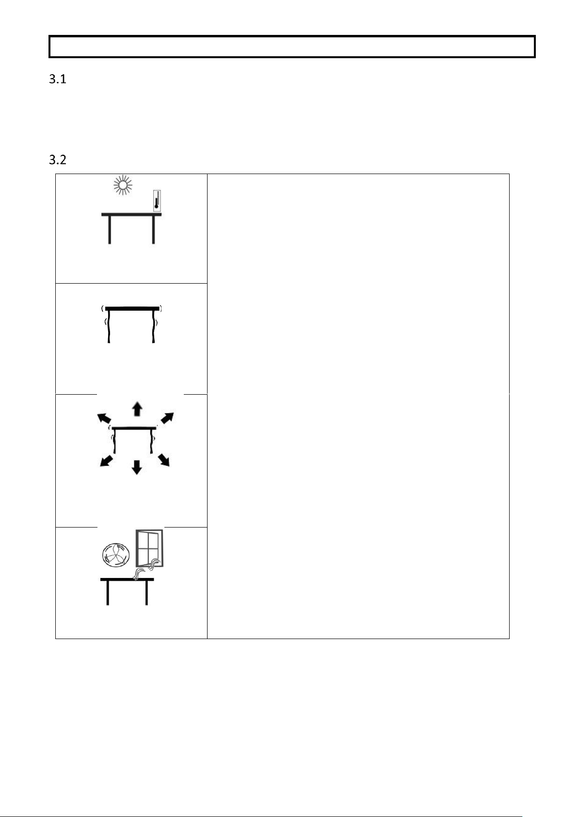
LOCATING
• The scale should not be placed in a location that will
reduce the accuracy.
• Avoid extremes of temperature. Do not place in
direct sunlight or near air conditioning vents.
• Avoid unsuitable tables. The table or floor must be
rigid and not vibrate.
• Avoid unstable power sources. Do not use near
large users of electricity such as welding equipment
or large motors.
• Do not place near vibrating machinery.
• Avoid high humidity that might cause condensation.
Avoid direct contact with water. Do not spray or
immerse the scale in water.
• Avoid air movement such as from fans or opening
doors. Do not place near open windows or airconditioning vents.
• Keep the scale clean. Do not stack material on the
scale when it is not in use.
Page 9

Page 5
SETTING UP THE SCALE
• Remove the Indicator from its box and fix it to the U shaped bracket using the
two fixing handles. Take the Indicator and place it onto the pillar ensuring the
slack cable is pushed inside. Fix the Indicator to the pillar using the screw
provided.
• Remove all upper internal packaging, place the pillar into the base bracket
fitting and remove the complete machine from the box. Remove any plastic
bags that may have been used for protection.
• Fix the pillar to the base bracket fitting using the screws provided
• Adjust the viewing angle of the Indicator to the ideal position and tighten two
the locking handles.
• Level the scale by adjusting the adjusting feet until the bubble is in the center of
the level indicator. If the scale rocks, re-adjust the feet.
NOTE: Use of a food-safe grease is recommended on the threaded part of
the feet to keep them turning freely.
• Attach the power input connector to the indicator, plug in and turn on the
external power supply and press the [On/Off] key. The software revision
number will be displayed followed by a self-test showing all digits before the
zero is displayed along with the unit of weight that was last used.
• Optional connections to RS232 port and relay wiring port should be made if
required.
Page 10
Page 6
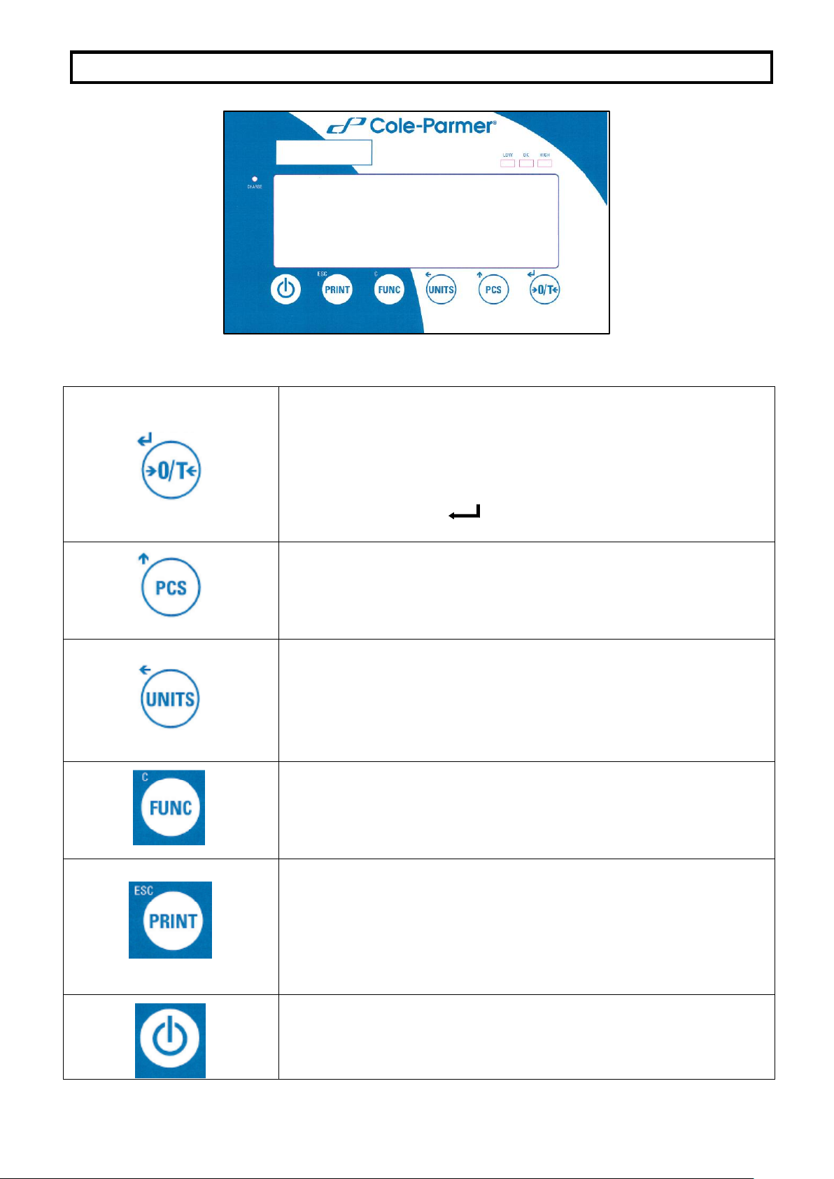
4.0 KEY DESCRIPTIONS
Used to reset the display to zero.
Tares the scale. Used to deduct and store the weight currently
on the scale if it is not required as part of the final weighing
result.
A secondary function, is of an “Enter” key used when
setting up a value for the Parameters.
Selects parts counting. Used to set the sample quantities while
parts counting.
A secondary function, is of incrementing the active digit when
setting a value for Parameters.
Selects the weighing unit to be displayed from those which are
enabled. See parameter S1 in section 7.4 of this manual.
A secondary function, is to move the active/flashing digit to
the left when setting values for Parameters.
Selects the Function parameters of the scale.
A secondary function (C) is to act as a clear key when clearing
an accumulated total.
Sends the results to a PC or a Printer using the RS-232
interface. It also adds the value to the accumulation memory if
the accumulation function is not automatic.
A secondary function (ESC) is to return to normal operation
when the scale is in a Parameter setting mode.
To switch the Indicator on or off.
The scale will store the weighing unit and the check weighing
values currently in use if power is powered off. These will be re
called when the Indicator is next powered on
Page 11

Page 7
5.0 DISPLAY
The LCD display will show a value as well as the unit currently being used. In addition the
LED’s above the display will show when a weight is below, inside or above the checkweighing limits.
Other symbols will show when a weight has been tared (NET), the scale is at zero and
stable, if a value has been stored in memory, or when the animal weighing function has been
enabled. A battery bar symbol will show the state of charge of the internal battery.
6.0 OPERATION
ZEROING THE DISPLAY
• You can press the [➔0/T] key at any time to set the display to zero. This will
usually be when the platform is empty. When the zero point is obtained the
display will show an indicator for zero.
• The scale has an automatic re-zeroing function to account for minor drifting or
accumulation of material on the platform. However you may need to press the
[➔0/T] key to re zero the scale if small amounts of weight are shown when
the platform is empty.
Page 12

Page 8
TARING
• Zero the scale by pressing the [➔0/T] key if necessary. The “ZERO”
indicator will be ON.
• Place a container on the platform and a value for its weight will be displayed.
• Press the [➔0/T] key to tare the scale. The weight is deducted and stored as
the tare value leaving zero on the display. The “NET” indicator will be ON and
as a product is added only the net weight of the product will be shown. The
scale could be tared a second time if another type of product was to be added
to the first one. Again only the weight that is added after taring will be
displayed.
NOTE: The “NET” indicator will only be ON when the tare weight exceeds
4% (+/- 2 weighing divisions) of the scale capacity.
• When the container is removed a negative value will be shown. If the scale was
tared just before removing the container this value is the gross weight which
includes the container and the entire product it contains. The “ZERO” indicator
will be on to indicate that the platform is back to the same condition as it was
when zero was last set.
• To delete a Tare value, press [➔0/T] when the pan is empty.
Page 13

Page 9
WEIGHING A SAMPLE
To determine the weight of a sample, first tare the empty container if it is to be used and then
place the sample in the container. The display will show the net weight of the sample and the
unit of weight currently in use.
PARTS COUNTING
If parts counting is enabled, it is possible to count parts using a sample of the parts to
determine average piece weight.
• Before starting, tare the weight of any container that may be used, leaving the
empty container on the scale. Place a known number of samples in the
container, if used. The number should match the options for parts counting, i.e.,
10, 20, 50, 100 or 200 pieces.
• When the scale is showing weight, pressing the [Pcs/] key will start the parts
counting function.
• The scale will show “P 10” asking for a sample size of 10 parts. Change the
sample size to the desired quantity by pressing the [Pcs/] key. It will cycle
through the options: 10, 20, 50, 100, 200 and back to 10.
• Press the [➔0/T] key again when the number matches the number of parts
used as the sample. As more weight is added the display will show the number
of parts (Pcs).
Page 14

Page 10
• Pressing the [Unit/] key will display the net weight (pcs and kg), pressing it
second time will display the unit weight (g/pcs) and the third time, it will be the
count again (pcs).
• Press the [Pcs/] key to return to normal weighing. Press the [Pcs/] key again
to start counting a different sample.
CHECK-WEIGHING
Check-weighing is a procedure to cause lamps to come on (and if enabled, an alarm to
sound) when the weight on the scale meets or exceeds values stored in memory. The
memory holds the last values for a high and a low limit when the power is turned off. The
user can set either one limit or both as described in section 7.1. The limits can be set when
the scale is in weighing or parts counting modes. After limits have been set the Checkweighing function is enabled.
When a weight is placed on the scale the LED’s above the display will show if the weight is
above or below the limits and the beeper will sound as described below, if the beeper is
enabled (see section 7.1).
The relay outputs are open collector drivers to control an external relay. The relays will be
active when the corresponding LED is on during check-weighing. The ZERO relay output will
be on when the scale is showing the display is at Zero.
ACCUMULATED TOTAL
• The scale can be set to accumulate manually by pressing the [Print/M+/Esc]
key or automatically when a weight is removed from the scale. See Section 7.3
for details of setting the Parameter “C3 PRM” and “C4 Aon”. The accumulation
function is available when weighing or when counting parts. However the
memory is cleared if the weighing units or functions are changed.
• When the weight (or count) displayed is stored in memory the display will show
“ACC 1” and then the total in memory for 2 seconds before returning to weighing.
The RS-232 interface will output to a printer or PC.
• Remove the weight, allowing the scale to return to zero and put a second
weight on. When this value is stored, the display will show “ACC 2”, then the
new total and finally the value of the second weight. Repeat as necessary to
add all the values needed to the memory.
• To view the total in memory press the [Print/M+/Esc] key when there is no
weight on the scale. The display will show the number of entries and the total.
• To clear the memory (set the value to zero) press the [Func/C] key during the
time the totals are being displayed.
Page 15

Page 11
PERCENT WEIGHING
The scale can be set to perform percent weighing. See Section 7.2.
The scale will use a mass on the platform as the 100% reference weight. If the platform is
empty (or the scale is tared) then the user can input a reference weight using the keypad.
NOTE: The weight value entered as 100% must be greater than 50 scale divisions. The
display may jump by large numbers unexpectedly if small weights are used to set
as 100% reference. The scale checks if the weight is too small and will show Error
7
• Press [Func/C]. The first option is “FunC 1”. press the [Func/C] key again display “FunC
2”.
• Press the [➔0/T] key. “P1 PCt” will be displayed.
• Press [➔0/T] again to enter percent weighing. The scale will set the sample mass
on the platform as 100% reference weight.
• Remove the sample weight. Then any other weight placed on the scale will be
displayed as a percentage of the original sample. For example, if 3500g is placed on
the scale and percent weighing is selected, the display will show 100.0%. Remove the
3500g weight and place a 3000g weight. The display will show 85.7% as 3000g is
85.7% of 3500g.
• The number of decimal points will depend on the weight used in comparison to the
capacity of the system. A smaller weight will show only “100%” while a larger weight
might show “100.00%”.
• If the scale was showing zero weight when entering this function, then the user must
manually enter the weight to be set as 100% as described below.
Page 16

Page 12
• Press the [➔0/T] key. “P1 PCt” will be displayed.
• Press [➔0/T] again to enter percent weighing. The scale will now accept a value
the user enters as the reference weight.
• Enter the value using the [Unit/] key and [Pcs/] key to select and set the value of
the 100% mass.
• When set, press the [➔0/T] key to store the value. The display will show “0.00 %”.
• Press [Unit/] to return to weighing.
ANIMAL (DYNAMIC) WEIGHING
The scale can be set to animal (dynamic) weighing for weighing any items that are unstable
or may move. See Section 7.4.
The scale will use a special filter to minimize the effects of any movement while the moving
animal or unstable samples are on the scale.
• Press [Func/C]. The first option is “FunC 1”, press the [Func/C] key again to display
“Func 2”.
• Press the [➔0/T] key. “F1 PCt” will be displayed. Press the [Pcs/] key to advance
to the second function, “P2 Ani”, Animal weighing.
• Press [➔0/T] to enter animal weighing. The scale will change to animal weighing
and allow weighing of an unstable animal or sample on the platform.
• To use the Animal Weighing function it is necessary to set the amount of filtering
required for the item to be weighed. The display will show “Flt x” where x is a value
from 1 to 5. The higher the value the greater the amount of filter will be. More active
animals will require a higher level of filtering to give a stable result. To increment the
value shown, press the [Pcs/] key then press the [➔0/T] key to accept it.
• The display will flash “Ani “ 2 times then show the current weight, 0.00. and the
Animal/Dynamic weighing symbol will appear. The scale is now ready to
weigh.
Page 17

Page 13
ANIMAL WEIGHING PROCEDURE
• With the platform empty the display will show zero weight. Place containers or
blankets onto the platform and press the [➔0/T] key to zero the display. The scale
may go into the animal (dynamic) weighing procedure when the items are placed on
the scale but will return to showing zero when the [➔0/T] key is pressed.
• Place the animal or sample to be weighed on the platform.
• The display will show the Animal/Dynamic weighing symbol while a stable weight
is determined. The time it takes for the stable value will depend upon the setting of the
filter parameter in the first step.
• When a stable reading is found, the display will show this value, and the display will
be locked until the [➔0/T] key is pressed. The display will show the “Hold” symbol
while the display is locked.
• To weigh a second subject press the [➔0/T] key if necessary to zero the display,
and place the next animal on the scale. The scale will detect the new weight and hold
it as before.
• The scale will remain in the animal weighing mode until the [Unit/] key is pressed.
Then it will return to normal weighing.
Page 18

Page 14
7.0 USER PARAMETERS
Pressing the [Func/C] key during normal operation allows the user to access the parameters
for customizing the scale. The parameters are split into 4 groups:-
1. Check weighing parameters,
2. Percent and Animal Weighing Functions
3. RS-232 parameters
4. Scale parameters
• When [Func/C] key is pressed, the display will first show “FunC 1” for Check weighing
parameters.
• Press either the [Func/C] key or the [Pcs/] to advance through the groups “FunC 1”,
“FunC 2” , “FunC 3” and “FunC 4”. When the required function is displayed, press
[➔0/T] to enter the sub-menu for setting desired parameters for this function.
• When in one of the sections press [Print/M+/Esc] to regress one step each time. If
you press [Print/M+/Esc] repeatedly, you will exit the User Parameter section and
return to normal weighing.
CHECK WEIGHING PARAMETERS
See section 6.5 for details of using this special weighing mode.
This group of parameters-
- Set low and high limits for check-weighing
- Enables or disables the check weighing alarm
- Enables or disables the negative check weighing
• Press the [Func/C] key, then [➔0/T], to access the “FunC 1” settings group “F1 Lo”
parameter.
• Press [➔0/T] to enter the settings sub-menu and then use the [Unit/] key and
[Pcs/] key to select and change the required weight values for the low limit.
• Press [➔0/T] to confirm the selection and return to “F1 Lo”. Advance to the next
parameter “F2 Hi” by pressing the [Pcs/] key and then [➔0/T] to enter the settings
sub-menu. Repeat the above steps to set values for “F3 bEP” and “F4 nCt”
Parameter
Description
Options
Default
setting
F1 Lo
Set Low limit.
Use the [Unit/] key and
[Pcs/] key to set the
values of the lower limit.
When set press the
[➔0/T] key to store the
value and go to F2 Hi
000000
F2 Hi
Set High limit.
Use the [Unit/] key and
[Pcs/] key to set the
values of the high limit.
When set press the
[➔0/T] key to store the
value and go to F3 bEP
0000000
Page 19

Page 15
F3 bEP
This parameter sets the
Beeper to off or on. If set to on,
the beeper can further be set
to sound when the weighing
result is within or outside the
check-weighing limits.
bP oFF - Off
bP inL - Within limits
bP otL - Outside limits
(>20d)
bP inL
F4 nCK
This parameter enables
negative check weighing
function with ability to do
negative tare.
on
oFF
on
PERCENT WEIGHING AND ANIMAL WEIGHING
See section 6.7 and 6.8 for details of using these special weighing modes.
• Press [➔0/T] to enter a parameter. Use the [Unit/] key and [Pcs/] key to set
the values or just the [Pcs/] key to select the options.
• Press [➔0/T] to confirm the change and then advance to the next parameter by
pressing the [Pcs/] key.
• Press [Print/M+/Esc] to return to the group “FUnC 2”. If you press [Print/M+/Esc]
again, the scale will exit the User Parameter section and return to weighing.
Parameter
Description
Options
Default
setting
P1 PCt
This parameter allows the user
to enter the Percent weighing
Function. See Section 6.7.
None
Enabled
always
P2 Ani
Enter the Animal Weighing
mode of operation, See section
6.8
Set the filter value.
Enabled
Always
RS-232 PARAMETERS
• Press [➔0/T] to enter a parameter. Use the [Unit/] key and [Pcs/] key to set
the values or just the [Pcs/] key to select the options.
• Press [➔0/T] to confirm the change and then advance to the next parameter by
pressing the [Pcs/] key.
• Press [Print/M+/Esc] to return to the group “FUnC 3”. If you press [Print/M+/Esc]
again, the scale will exit the User Parameter section and return to weighing.
This group of parameters can be configured by the user for setting the RS-232 active or not,
baud rate, printing mode, accumulation mode, RS-232 language, and user or scale ID
numbers.
Parameter
Description
Options
Default Values or
setting
C1 on
Enable or disable the
RS-232 interface
Prt on
Prt oFF
Prt on
Page 20

Page 16
C2 bd
Baud Rate
600
1200
2400
4800
9600
19200
9600
C3 PrM
Printing Mode- Manual,
Continuous or
Automatic
mAn,
Cont
AUto
mAn
C4 Aon
Enable or disable the
Accumulation
AC on
AC oFF
AC on
C5 Ln
Select Language
EnGLi (English)
FrEnCH (French)
GErmAn (German)
SPAn (Spanish)
EnGLi
C6 UId
Set User ID
To be entered manually
000000
C7 Sid
Set Scale ID
To be entered manually
000000
Scale will perform the following, depending on the Accumulation and Print Settings:
ACCUMULATION
SETTINGS
PRINT SETTINGS
AC on
AC Off
AUto
Accumulate and print
automatically
Print automatically,
Do not accumulate
mAn
Accumulate and Print only
when [Print/M+/Esc] key
pressed. If [Print/M+/Esc]
is pressed a second time
only print the weight.
Print when [Print/M+/Esc] key is
pressed,
Do not accumulate.
Cont
Print continuously.
Accumulate when
[Print/M+/Esc] key is
pressed
Print continuously.
Do not accumulate.
SCALE PARAMETERS
• Press [➔0/T] to view the list of parameters.
• Press [➔0/T] to enter a parameter. Use the [Unit/] key and [Pcs/] key to set
the values or just the [Pcs/] key to select the options.
• Press [➔0/T] to confirm the change and then advance to the next parameter by
pressing the [Pcs/] key.
• Press [Print/M+/Esc] to return to the group “FUnC 4”. If you press [Print/M+/Esc]
again, the scale will exit the User Parameter section and return to normal weighing.
Page 21

Page 17
This group of parameters is used to control the operation of the scale.
Parameter
Description
Options
Default
setting
S1 Un
Enable or disable weighing
units, will not allow to
disable all units, at least one
has to be enabled. Parts
counting can be
enabled/disabled
Kg
Grams
lb
oz
lb:oz
N (Newtons)
PCS
Kg
S2 bL
Backlight set to always on,
always off or automatic on
whenever a weight is placed
or a key is pressed
EL oFF
EL on
EL AU
EL AU
S3 AoF
Auto Off- Disable or set time
increment to turn off scale
SLP 0
SLP 1
SLP 5
SLP 10
SLP 0
S4 dt
Set Time and Date format
and settings.
Format for date can be
changed when the display
shows mmddyy, ddmmyy or
yymmdd by pressing the
[Pcs/] key, then enter the
date.
Enter the time manually.
Enter the date format
and then the numeric
value manually.
00:00:00
mm:dd:yy
S5 diS
Display all weights or only
when stable
ALL, StAb
ALL S6 Fi
Filter setting to slow, normal
or fast
Slow, nor, FASt
nor
S7 SPS
Password
Enter new pass word
twice. Controls access
to Func 1 to Func 4
Not active
S8 CAL
Calibration
Calibrate the scale. See
Section 11.0
-
Page 22

Page 18
8.0 BATTERY OPERATION
• The scale can be operated from the battery if desired. The battery life can be
up to 70 hours depending on the load cells and how the backlight is used.
• A battery symbol is shown on the display which indicates the current charge of
the battery, 3 bars means fully charged. When just the outline of the battery and
no bars are visible the battery needs to be re charged.
• To charge the battery, simply plug the adaptor into the mains power, and also
into the input connector on the rear of the Indicator marked DC 12V. The scale
does not need to be turned on.
• The battery should be charged for 12 hours to reach full capacity.
• Near the display is an LED to indicate the status of battery charging. When the
scale is plugged into the mains power the internal battery will be charged. If the
LED is green the battery has a full charge. If it is red the battery is nearly
discharged and yellow indicates the battery is being charged.
9.0 RS-232 INTERFACE
The indicator can be supplied with an optional bi-directional RS-232 interface. The scale,
when connected to a printer or computer outputs the weight with the selected weighing unit
through the RS-232 interface.
RS-232 serial interface plug (As viewed from the back of the indicator):
1: Pin GND, Signal Ground
2: Pin RXD, Received Data
3: Pin TXD, Transmitted Data
4: Not connected
The scale can be set to print text in English, French, German or Spanish. See the RS-232
parameters section for details.
RS-232 output of weighing data
ASCII code
600 - 19200 Baud (user selectable, default 9600)
8 data bits
No Parity
1 stop bit
No flow control
Page 23

Page 19
Data Format - Normal Output:
Only weight value along with the weighing unit is printed. If Percent weighing is used then %
is shown in place of weighing units.
Data Format - Parts Counting Output:
Weight, Unit weight and number of parts are printed.
Data Format - Memory Recall Output:
<cr><lf>
<cr><lf>
Date 12/09/2006 <cr><lf>
Time 14:56:27 <cr><lf>
<cr><lf>
Scale ID 123456 <cr><lf> If ID is zero, it is left blank
User ID 234567 <cr><lf>
<cr><lf>
Net Wt 1.234 Kg <cr><lf> Net Wt. (or Gross Wt.)
<cr><lf>
<cr><lf>
<cr><lf>
<cr><lf>
<cr><lf>
<cr><lf>
Date 12/09/2006 <cr><lf>
Time 14:56:27 <cr><lf>
<cr><lf>
Scale ID 123456 <cr><lf>
User ID 234567 <cr><lf>
<cr><lf>
Net Wt. 1.234 Kg <cr><lf> Net Wt. (or Gross Wt.)
Unit Wt. 123 g <cr><lf> g for metric and lb for pounds
PCS 10 pcs <cr><lf>
<cr><lf>
<cr><lf>
<cr><lf>
<cr><lf>
<cr><lf>
Date 12/09/2006 <cr><lf>
Time 14:56:27 <cr><lf>
<cr><lf>
Scale ID 123456 <cr><lf>
User ID 234567 <cr><lf>
<cr><lf>
------------------<cr><lf>
TOTAL
No. 5 <cr><lf>
Wt. 1.234 Kg <cr><lf>
<cr><lf>
PCS 10 pcs <cr><lf>
------------------<cr><lf>
Page 24

Page 20
Data Format - Continuous Output, Normal weighing:
Data Format - Continuous Output, Parts Counting:
NOTE:
1. The accumulated total will not be sent to the RS-232 when continuous print is on.
2. Continuous print will only be for the current weight and the display data.
3. In other languages the format is the same but the text will be in the language selected.
Description
ENGLISH
FRENCH
GERMAN
SPANISH
Net weight
Net Wt.
Pds Net
Net-Gew
Pso Net
Weight per unit
counted
Unit Wt.
Pds unit
Gew/Einh
Pso/Unid
Number of items
counted
Pcs
Pcs
Stck.
Piezas
Number of
weighing added
to subtotals
No.
Nb.
Anzhl
Num.
Total weight and
count printed
Total
Total
Gesamt
Total
Print date
Date
Date
Datum
Fecha
Print time
Time
Heure
Zeit
Hora
Scale ID number
Scale ID
Bal ID
Waagen ID
Bal ID
User ID Number
User ID
Util ID
Nutzer ID
Usuario ID
ST,GROSS 1.234 Kg <cr><lf> ST or US for STable or UnStable,
US,NET 0.000 Kg <cr><lf> NET or GROSS for Net Weight
or Gross wt. and the weighing unit, kg, lb etc.
ST Net 1.234 Kg <cr><lf> Net Weight (or Gross wt.)
U.W. 123 g <cr><lf> Kg and g for metric and Lb for pounds
PCS 10 pcs <cr><lf>
<cr><lf>
<cr><lf>
Page 25

Page 21
INPUT COMMANDS FORMAT
The scale can be controlled with the following commands. Press the [Enter] key of the PC
after each command.
T<cr><lf>
Tares the scale to display the net weight. This is the same as pressing
[➔0/T].
Z<cr><lf>
Sets the zero point for all subsequent weighing. The display shows
zero.
P<cr><lf>
Prints the results to a PC or printer using the RS-232 interface. It also
adds the value to the accumulation memory if the accumulation
function is not set to automatic.
10.0 RELAY INTERFACE
The indicator is supplied with drivers to control external relays. The drivers can be used to
control a number of different relays depending upon the users need. The relay drivers are
isolated outputs requiring the use of an external power supply for the relays.
The output to drive external relays is on the circuit board inside the enclosure. To gain
access you must remove the 6 screws securing the front to the rear of the case. Pass the
wires for the relays through the grommet on the rear panel. The wires will connect to the
PCB using the terminal strip P1.
ZERO
LOW
OK
HI
COM
SHIE
SEN+
EXE-
EXE+
SIG+
SIG-
SEN-
09/01/2009
AE9721 VER B
RXT
TXT
GND
BT1
C18
U5
U4
Q5
Power1
LC1
COM1
U1
P1
Relay Output
Common
High
OK
Low
Zero
RS-232 Interface
Load Cell Input
Power Connector
Battery Vin
+ - no polarity
Clock Battery
CR1220 type
The circuit to control the relays requires an external voltage compatible with the relays used.
Contact your supplier for a relay interface that is compatible with the relay drivers, however
other interfaces can be used as long as the following conditions apply.
Page 26

Page 22
Connections to the relay drivers:
Connections are made to the PCB, Connector P1. The connector is a spring activated type,
simply press on the top of the connector and insert the wire.
Do not exceed the safe limits of voltage or current of 24VDC or 15ma per output.
Depending upon the application it may be necessary to use a small relay to drive larger
relays, or to provide additional protection to prevent electromagnetic interference (diodes as
shown above) to this or other machinery.
11.0 CALIBRATION
The scale can be calibrated using the following procedure. To enter this procedure it is
necessary to use Func 4 which is accessible using the [Func/C] key as described in section
7.4 in the full manual, or by using the passcode access as described in section 12.0.
The scale calibrates using either metric or pound weights depending on the weighing unit
being used before calibration. The display will show either "kg" or "lb" to identify the weights
expected.
PROCEDURE
• Enter the calibration section using Func 4, C8 CAL or using the passcode as
described in section 12.0.
• The display will show "unLoAd".
• Remove any weight from platform and when the stable symbol is on press
[➔0/T].
• The display will show "Ld" then “0000XX” which shows the last calibration weight
used. Place this calibration weight on the scale and press the [➔0/T] key. If
the weight you put on the scale does not match the value displayed, press the
[Func/C] key to clear the vale then use the [Unit/] key and [PCS/] key to
set the correct value. When it is correct press [➔0/T].
• If the calibration is acceptable the scale will run a self-test during which the
calibration weight should be removed. If an error message “FAiL L” is shown try
calibration again as a disturbance may have prevented a successful calibration.
After calibration the scale should be checked to verify the calibration is correct. If necessary
repeat the calibration making sure that the scale is stable before accepting any weight.
Page 27

Page 23
12.0 SERVICE PARAMETERS
The scale will allow entry to the parameters if the [Tare] key is pressed during the power on
cycle. The passwords work as above.
In this case the display will show the passcode request screen, “ P - - - - “ . To continue enter a
passcode as described below.
Entering passcode 0000 will allow calibration as shown in section 11.
Entering 1000 will allow access to a limited set of parameters described in section 12.1.
USING “1000” TO ENTER THE SERVICE PARAMETERS
Press the [➔0/T] key during the display counting when turned on,
When “Pn “ is displayed, enter the number 1000 using the [Unit/] and [Pcs/] keys and
then press [➔0/T].
The displays will show the first parameters, called “F4 Int”.
To select another parameter press the [Pcs/] key to advance through the parameters.
Press the [➔0/T] key to enter a parameter.
To exit a parameter, press the [Print/M+/Esc] key.
The display will show the parameter number and a name.
When a parameter is entered by pressing the [➔0/T] key, the displays will guide you
through the parameter selected and the options available.
The parameters available are:
“F4 Int” Initial Zero Range
“F5 rEZ” Re-Zero range
“F6 SCS” Successive Tare Enable
“F7 Cnt” Display the A/D counts
“F8 Zem” Zero Mode
“F9 Lvd” Low voltage detection
“FA AZn” Auto Zero Range
“Fb FPS” User Function Password
The description of the parameters is shown in section 12.2.
Page 28

Page 24
USING THE SERVICE PARAMETERS
F4 –INITIAL ZERO RANGE
To enter this parameter, press the [➔0/T] key when “F4 int” is shown.
The display will show the current initial zero range.
Press the [Pcs/ ] key to change the value and press [➔0/T] to accept the value.
Press [Print/M+/esc] to return to weighing.
F5 -RE-ZERO RANGE
To enter this parameter, press the [➔0/T] key when “F5 rEZ” is shown.
The display will show the current re-zero range.
Press the [Pcs/] key to change the value.
Press [➔0/T] to accept the value.
Press [Print/M+/esc] to return to weighing.
F6 -SUCCESSIVE TARE
To enter this parameter, press the [➔0/T] key when “F6 SCS” is shown.
The display will show if the successive tare is on or off.
Press the [Pcs/] key to change the value.
Press [➔0/T] to accept the displayed value.
Press [Print/M+/Esc] to return to weighing.
F7 –ADC COUNTS
To enter this parameter, press the [➔0/T] key when “F7 Cnt” is shown.
This parameter allows you to view the A/D counts from the internal A/D converter. This can
be an aid to service.
Press the [➔0/T] key to return to the PARAMETER menu.
Press the [Print/M+/Esc] key to return to weighing.
Typical value at zero is 30,000-90,000 (approx.).
Typical value at full capacity is 500,000 (approx.).
F8 –ZERO MODE
To enter this parameter, press the [➔0/T] key when “F8 ZEm” is shown.
Select the Zero mode desired. In all but special cases Zero Mode 1 is used. The other 2
zero modes are for unique locations in the world and effect the +/- range of the zero.
Press the [Pcs/] key to change the value.
Press [➔0/T] to accept the displayed value.
Press [Print/M+/Esc] to return to weighing.
Page 29

Page 25
F9 –LOW VOLTAGE DETECTION
This parameter allows detection of low voltage when the battery wears down.
To enter this parameter, press the [➔0/T] key when “F9 LVd” is shown.
The display will show if the LVD Mode is set to on or oFF.
Press the [Pcs/] key to change the value.
Press [➔0/T] to accept the displayed value.
Press [Print/M+/Esc] to return to weighing.
FA –AZn Auto Zero Range
This parameter sets the auto zero range from 0 (Off) to 4d.
Calibration and parameter counting function to be active. To enter this parameter, press the
[➔0/T] key when “FA AZn” is shown.
The display will show if the current Auto Zero range.
Press the [Pcs/] key to change the value.
Press [➔0/T] to accept the displayed value.
Press [Print/M+/Esc] to return to weighing.
Fb –FPS User Function Password
This parameter set a password to control access to the user functions as described in
Section 7. If the password is set to 0000 the control is disable and the user has free access
to the functions.
To enter this parameter, press the [➔0/T] key when “Fb FPS” is shown.
The display will show “P1 - - - -“ Enter the new password code followed by [➔0/T] to accept.
The display will then show “P2 - - - -“ Enter the new password code again followed by
[➔0/T] to accept. The same code number must be entered both times for the password to
be set.
Press the [Unit/] and [Pcs/] keys to enter the values.
Press [Print/M+/Esc] to return to weighing.
Page 30

Page 26
13.0 ERROR CODES
ERROR
CODES
DESCRIPTION
SUGGESTIONS
- -oL - -
Over-range
Remove weight from the scale.
If the problem persists contact your supplier for assistance.
Err 1
Time Setting Error
Enter time using correct format and reasonable values.
Format: hh:mm:ss
Err 2
Date Setting Error
Enter date using correct format and reasonable values.
Format: yy:mm:dd
Err 4
Zero Setting Error
The scale was outside the normal zero setting range either
when it was turned on, or when the [Zero] key was
pressed.
Remove weight from the scale and try re-zeroing again.
Use the [➔0/T] key to set the display to zero value.
If the problem persists contact your supplier for assistance.
Err 6
A/D out of range
The values from the A/D converter are outside the normal
range.
Remove the weight from the scale if overloaded.
Make sure the pan is fitted correctly.
Indicates the load cell or the electronics may be faulty.
If the problem persists contact your supplier for assistance.
Err 7
100% weight out of
range
Weight value set as 100% for percentage weighing must be
greater than 50 weighing divisions of the scale.
Err 9
Check weigh limits
error
Shown if the low limit is set higher than the current high
limit. Reset High limit or change the low limit.
FAIL
Calibration error.
Improper calibration (should be within + 10% of the factory
calibration). The old calibration data will be retained until the
calibration process is complete.
If the problem persists contact your supplier for assistance.
14.0 REPLACEMENT PARTS AND ACCESSORIES
If you need to order any spare parts and accessories, contact your supplier. A partial list of
such items is as follows:
• Power Supply Module
• Replacement Battery
• Replacement feet
• Replacement screws and brackets
• Printer, printer paper etc.
• RS232 connector cable
• Replacement top pan
• Relay interface parts
Page 31

Page 27
15.0 SERVICE INFORMATION
This manual covers the details of operation. If you have a problem with the scale that is not
directly addressed by this manual then contact your supplier for assistance. In order to
provide further assistance, the supplier will need the following information which should be
kept ready:
A. Details of your company
- Name of your company:
- Contact person’s name:
- Contact telephone, e-mail,
- Fax or any other methods:
B. Details of the unit purchased
(This part of information should always be available for any future
correspondence. We suggest you to fill in this form as soon as the unit is
received and keep a print-out in your record for ready reference.)
Model name of the scale:
Serial number of the unit:
Software revision number
(Displayed when power is first turned on):
Date of Purchase:
Name of the supplier and place:
C. Brief description of the problem
Include any recent history of the unit. For example:
-Has it been working since it’s delivered
-Has it been in contact with water
-Damaged from a fire
-Electrical Storms in the area
-Dropped on the floor, etc.
Page 32

Page 28
16.0 WARRANTY INFORMATION
The scale is covered by a Limited Warranty (Parts and Labor) for any components that fail due to defects in
materials or workmanship. Warranty starts from the date of delivery.
During the warranty period, should any repairs be necessary, the purchaser must inform its supplier. The company or
its authorized Technician reserves the right to repair or replace the components at any of its workshops at no
additional cost, depending on the severity of the problems. However, any freight involved in sending the faulty units
or parts to the Service Centre should be borne by the purchaser.
The warranty will cease to operate if the equipment is not returned in the original packaging and with correct
documentation for a claim to be processed.
This warranty does not cover equipment where defects or poor performance is due to misuse, accidental damage,
exposure to radioactive or corrosive materials, negligence, faulty installation, unauthorized modifications or
attempted repair, or failure to observe the requirements and recommendations as given in this User Manual.
This product may include a rechargeable battery that is designed to be removed and replaced by the user. The
supplier will provide a replacement battery if the battery manifests a defect in materials or workmanship during the
initial period of use of the product in which the battery is installed.
As with all batteries, the maximum capacity of any battery included in the product will decrease with time or use, and
battery cycle life will vary depending on product model, configuration, features, use, and power management
settings. A decrease in maximum battery capacity or battery cycle life is not a defect in materials or workmanship,
and is not covered by this Limited Warranty.
Repairs carried out under the warranty do not extend the warranty period. Components removed during warranty
repairs become company property.
The statutory rights of the purchaser are not affected by this warranty.
Page 33

Page 29
WEEE 2012/19/EU
This device may not be disposed of in domestic waste. This also applies to countries outside the EU, per their
specific requirements. Disposal of batteries (if fitted) must conform to local laws and restrictions.
Cet appareil ne peut être éliminé avec les déchets ménagers. L’élimination de la batterie doit être effectuée
conformément aux lois et restrictions locales.
Dieses Gerät nicht mit dem Hausmüll entsorgt.
Dispositivo no puede ser desechado junto con los residuos domésticos
Dispositivo non può essere smaltito nei rifiuti domestici.
FCC / IC CLASS A DIGITAL DEVICE EMC VERIFICATION STATEMENT
NOTE: This equipment has been tested and found to comply with the limits for a Class A digital device,
pursuant to Part 15 of the FCC rules and Canadian ICES-003/NMB-003 regulation. These limits are
designed to provide reasonable protection against harmful interference when the equipment is operated
in a commercial environment. This equipment generates, uses and can radiate radio frequency energy
and, if not installed and used in accordance with the instruction manual, may cause harmful
interference to radio communications. Operation of this equipment in a residential area is likely to
cause harmful interference in which case the user will be required to correct the interference at his own
expense.
CALIFORNIA PROPOSITION 65 - MANDATORY STATEMENT
WARNING: This product includes a sealed lead-acid battery which contains chemicals known to the
State of California to cause cancer and birth defects or other reproductive harm.
This product has been tested with, and is supplied with power adaptors which meet all legal
requirements for the intended country or region of operation, including electrical safety,
interference and energy efficiency. As we often update adaptor products to meet changing
legislation it is not possible to refer to the exact model in this manual. Please contact us if you
need specifications or safety information for your particular item. Do not attempt to connect or
use an adaptor not supplied by us.
 Loading...