

Page 1

IPS Series
Bench Scales
User Manual
xxxxxxxxxx - Revision __, June 2017
Page 2

Page 3

P a g e 3
CONTENT
1.0 SETTING UP AND TURNING ON THE SCALES ................................ 5
2.0 OPERATION ........................................................................................ 5
2.1 ZEROING .......................................................................................... 5
2.2 TARING ............................................................................................. 5
2.3 PARTS COUNTING .......................................................................... 6
2.4 PERCENT WEIGHING ................................................................ ...... 6
2.5 ANIMAL (Dynamic) WEIGHING ......................................................... 8
2.6 ACCUMULATED TOTAL ................................................................... 9
3.0 RS-232 SPECIFICATION ................................................................... 10
4.0 CALIBRATION .................................................................................... 11
5.0 SPECIFICATIONS .............................................................................. 13
6.0 ERROR MESSAGES.......................................................................... 14
7.0 MENU STRUCTURE .......................................................................... 15
8.0 WARRANTY INFORMATION ............................................................. 16
Page 4

P a g e 4
Page 5
P a g e 5
1.0 SETTING UP AND TURNING ON THE SCALES
There is a pillar which must be attached to the base frame first using the 4 bolts supplied. The pillar is
secured to the bracket using 2 sets of screws. Then place the platform in the base. Level the scale by
adjusting the four feet. Attach the indicator module to the pillar by sliding it over the bracket with the flanges
engaged in the groves on the base. Attach the cable from the base to the connector on the rear of the
indicator. Attach the power to the indicator.
After completion of setting up, press the [On/Off] key on the rear of the indicator. The software revision
number will be displayed followed by a self-test showing all digits before the zero is displayed along with the
unit of weight that was selected last.
NOTE: The IPS can be operated from the rechargeable battery. With a single load cell and backlight
disabled the life is approximately 70 hours before needing to be recharged. The battery should be charged
for 12 hours for full capacity.
2.0 OPERATION
2.1 ZEROING
You can press the [Zero] key at any time to set the zero point from which all other weighing and counting is
measured. The scales have an automatic re-zeroing
function to account for minor drifting or accumulation of
material on a connected platform. However you may
need to press [Zero] to re-zero the indicator if small
amount of weight is still shown when the platform is
empty.
2.2 TARING
To determine a weight of sample which is using a container, you need to tare the empty container. IPS
scales supply two methods of tare: manual tare and preset tare.
Manual Tare
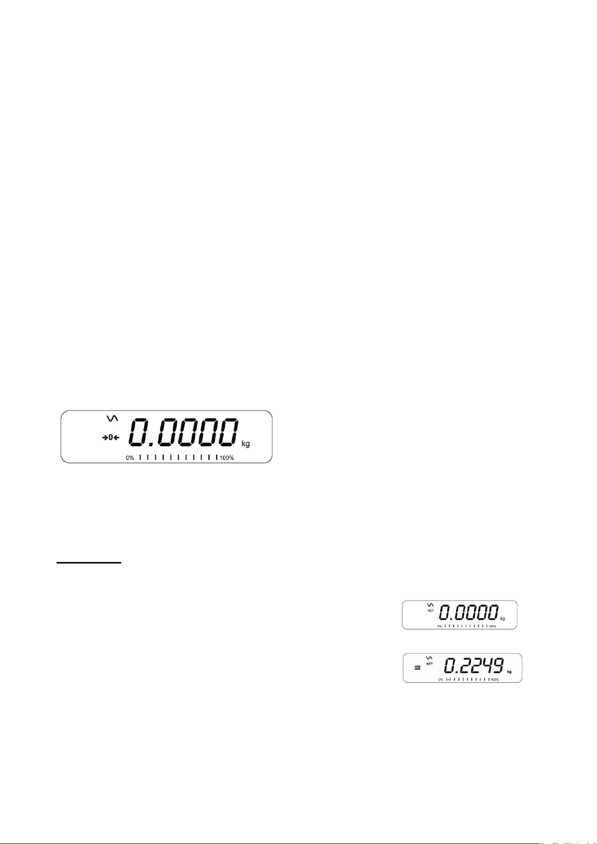
Zero the indicator by pressing [Zero]. The zero indicator will be on. Place a container on the pan.
Press [Tare] when the reading is stable. The weight that was displayed is
stored as the tare value, leaving zero on the display. The stable and Net
indicator will be on.
As a sample is added only the weight of the product will be shown. The
indicator could be tared a second time if another type of product was added
to the first one.
Press [Tare] or [Zero] to remove the tare value and display zero. The Net indicator will disappear.
Page 6
P a g e 6
Preset Tare
When the indicator or scale is at zero with no weight on the platform it is possible to enter a preset tare. First
zeroing the scale, enter a value using the numeric keys. Press [Tare] to tare the indicator. The value that
was entered is stored as the tare value and it is subtracted from the display, leaving a negative number on
the display.
To change the weighing unit press the [Unit] key. The only alternative weighing unit is pounds.
2.3 PARTS COUNTING
The scale can be used to count parts based on the average weight of a sample weighed. If a container is to
be used, place this container on the platform before entering parts counting and press [Tare]. Press [Cnt] to
enter the Parts Counting mode.
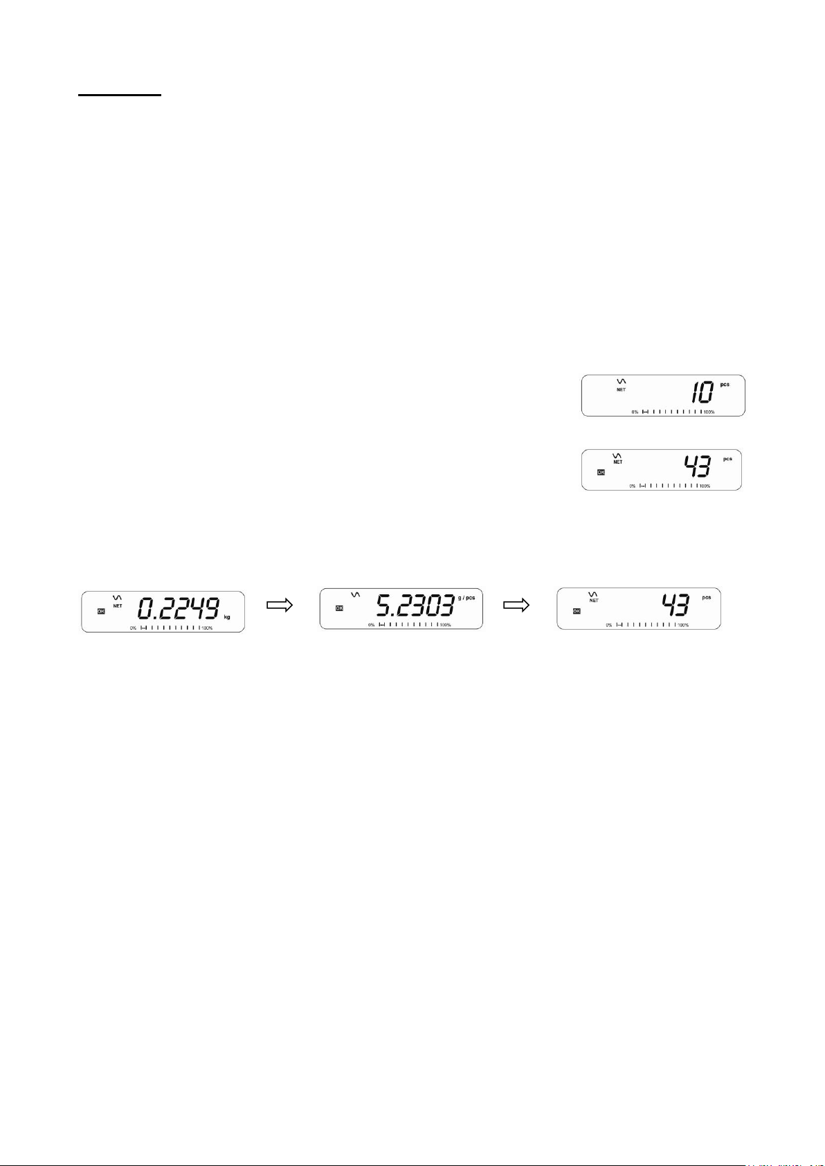
The display will show the last sample size used. For example, “10 Pcs”. To
change the sample size, you can press [CE] to clear the last values and then
enter the value 20 using the numeric keypad.
Place the right number of parts on the platform. Then press [Cnt] to determine
an average piece weight. After the sample has been weighed the scale will
count any other parts added by applying the average piece weight to the weight
of the parts to be counted.
During parts counting the display can be changed to show the net weight, unit weight and number of parts by
each time pressing the [Func] key.
To count a different sample quantity, press the [Count] key. And operate as above. To return to weighing,
press [Unit] when “XX pcs” is displayed.
NOTE: If the parts are too light to measure accurately, the count may become faulty. It is suggested that the
samples to be weighed should each weigh more than the resolution of the indicator.
2.4 PERCENT WEIGHING
The scale will use a mass on the platform as the 100% reference weight or input a reference weight using
the keypad.
Steps:
If using a reference weight (or object) as your 100% reference, add the weight to the platform. Press [Func].
The first option is “FUnC 1”, press the [Func] key 3 more times to display “FUnC 4”
Press the [Tare] key. “F4 PCt” will be displayed. Press [Tare] again to enter percent weighing. The scale will
set the sample mass on the platform as 100% reference weight.
NOTE: If there is no reference weight on the pan and percent weighing function is entered, pressing [Tare]
again will return the indicator to normal weighing.
Remove the sample weight. Then any other weight placed on the platform will be displayed as a percentage
of the original sample.
Page 7

P a g e 7
Users can also input the reference weight using the keypad. Make sure the platform is empty and when “F4
PCT” is displayed, enter the weight to be used for the 100% reference, then press [Tare] to accept the
reference weight. The display will show “0.00 %”.
If the indicator shows “x x . x x %”, which is the last weight used as a reference, press [CE] to clear and use
the numeric keypad to enter a new value. Press [Tare] to accept the new reference weight.
Press [Unit] to return to normal weighing.
NOTE: The weight entered must be greater than 50 scale divisions.
The display may jump by large numbers unexpectedly if small weights are used to set as 100% reference.
The indicator checks if the weight is too small and will show Error 7.
Page 8

P a g e 8
2.5 ANIMAL (DYNAMIC) WEIGHING
Steps:
Press [Func]. The first option is “FUnC 1”, press the [Func] key 3 more times to display “Func 4”.
Press the [Tare] key. “F4 PCt” will be displayed. Press the [Func] key to advance to the second function, “F4
AnL”, Animal weighing. And Press [Tare] to enter.
To use the Animal Weighing function it is necessary to set the amount of filtering. More active animals will
require a higher level of filtering to give a stable result. The display will show “Filt x” where x is a value from 1
to 5. To increment the value shown press the [Func] key then press the [Tare] key to accept it.
The display will flash “Ani “ 2 times then show the current weight, 0.00. The scale is now ready to weigh.
Place containers or blankets onto the platform and press the [Tare] key to zero the display. Place the animal
to be weighed on the platform.
When a stable reading is found, the display will show and lock this value, The display will show the “Hold”
symbol .Remove the animal, the display will hold the weight value.
Press the [Unit] key to unlock the display. The display will flash “Ani” twice, and be ready for the next
animal.
Press [zero] key to return to normal weighing.
Page 9

P a g e 9
2.6 ACCUMULATED TOTAL
The indicator can be set to accumulate when a weight is added to the platform automatically or manually by
pressing [Print]. See menu structure section. The accumulation function is available only during weighing. If
at any time the weighing units are changed, the accumulated data will be lost.
Manual Accumulation
When the scale is set to manual accumulation, the weight displayed will be stored in the memory when the
[Print] key is pressed and the weight is stable.
Steps :
Remove the weight and press [Print] when the display is at zero. The display
will show "ACC 1" and then the weight in memory for 2 seconds before returning
to normal. The weight can be output to a printer or PC using the RS-232
interface.
When the indicator is at zero, place a second weight on the platform. When
stable, press [Print] to accumulate the weight. The display will show "ACC 2"
for 2 seconds and then show the new total.
Continue until all weights have been added. This can continue for up to 99 entries until the capacity of
display is exceeded.
To view the total in memory, press the [Print] key when the indicator is at zero. The display will show the
total number of accumulation "ACC xx" and the total weight before returning to zero.
To print the total, press [Print] to recall and then immediately press [Print] the second time to print the
results. To erase the memory, press [Print] to view the total and then immediately press [CE] to clear the
memory.
Automatic Accumulation
When the indicator has been set to Automatic Accumulation the value will be stored in memory automatically.
Place a weight on the platform. The beeper will sound when the display is stable indicating the value is
accepted. Remove the weight. The display will show "ACC 1" and then the total in the memory before it
returns to zero. Adding a 2nd weight will repeat the process.
While the weight is on the platform, press the [Print] key to view the values- first the accumulation number
"ACC x" and then the total will be shown.
Page 10

P a g e 10
3.0 RS-232 SPECIFICATION
The IPS scale is supplied with a bi-directional RS-232 interface. The indicator when connected to a printer or
computer outputs the weight with the selected weighing unit through the RS-232 interface.
Default Specifications:
Connector:
RS-232 output of weighing data
ASCII code
9600 Baud (user selectable)
8 data bits
No Parity
9 pin d-sub miniature socket
Pin 3 Output
Pin 2 Input
Pin 5 Signal Ground
Page 11

P a g e 11
4.0 CALIBRATION
The scale can be calibrated using kilogram weights or pound weights depending on the weighing unit
selected at the time of calibration.
Steps:
To start the calibration, turn the scale off and switch on again and then press [Tare] during the self-test.
Enter code number 0000 and press [Tare]. This will take you directly to the calibration section or you can get
into the calibration section through the Indicator Settings (“FUnC 3”- see menu structure).
The display will show "UnLoAd"
Remove all weight from the platform and then press the [Tare] key when the display is stable. After the Zero
point is set, the display will show “Ld xx”. Place the suggested calibration mass on the platform. It is best to
use a weight close to the full capacity of the indicator.
If the mass is different from the displayed value, enter the value of the mass in whole numbers. The kg or
the lb symbol will be on to show the active unit. Press the [Tare] key when the stable indicator is on.
When complete, it will display “PASS” and then either display “S8 CAL” (if entered the calibration section
through the Scale Settings) or return to normal weighing (if entered directly). Remove the calibration mass.
If an error message “FAIL H” or “FAIL L” is shown, re-check the calibration and repeat. If the error cannot be
corrected contact your supplier.
Page 12

P a g e 12
Page 13

P a g e 13
5.0 SPECIFICATIONS
IPS Models
Model #
IPS 30
IPS 50
IPS 100
IPS 150
IPS 300
Maximum Capacity
30lb/15kg
50lb/25kg
100lb/50kg
150lb/75kg
300lb/150kg
Readability
0.001lb/0.0005kg
0.002lb/0.001kg
0.005lb/0.002kg
0.01lb/0.005kg
0.02lb/0.01kg
Repeatability (Std Dev)
0.002lb/0.0010kg
0.004lb/0.002kg
0.010lb/0.004kg
0.02lb/0.01kg
0.04lb/0.02kg
Linearity +
0.003lb/0.0015kg
0.006lb/0.003kg
0.015lb/0.006kg
0.03lb/0.015kg
0.06lb/0.04kg
Units of Measure
Kilograms and pounds, grams for all except IPS 300 which is kg and lbs only.
Stabilization Time
2-3 Secs
Operating Temperature
-10°C to +40°C / +14°F to +104°F
Power Supply
12vDC 800mA UL/CSA adapter for USA
Calibration
External
Calibration Mass
User Selectable
Display
Backlit Green display 20mm with capacity tracker
Scale Housing
Welded steel painted base, stainless steel grade 304 Top pan, ABS indicator housing
Pan Size
300mm x 400mm x 50mm / 11.8” x 15.7” x 2”
400mm x 500mm x 50mm / 15.7” x 19.7” x 2”
Overall Dimensions
(w x d x h)
300mmx 520mm x 660mm / 11.8” x 20.5” x 26”
400mm x 620mm x 660mm / 15.7” x 23.7” x 26”
Net Weight
7.6kg / 16.8 lb
Features
Weighing/Counting/ Percentage/Hold function/RS232
Page 14

P a g e 14
6.0 ERROR MESSAGES
During the initial power-on testing or during operation, the indicator may show an error message. The
meaning of the error messages is described below.
If an error message is shown, repeat the step that caused the message. If the error message is still shown
then contact your dealer for support.
ERROR
CODE
DESCRIPTION
POSSIBLE CAUSES
Err 1
Time input Error
Invalid time entry such as “268970” for the time
format “H-m-S”.
Err 2
Date input Error
34th day of a month is an invalid entry.
Err 4
Initial Zero is greater than allowed
(4% of maximum capacity) when
power is turned on or when the
[Zero/Enter] key is pressed.
Weight on the platform when turning the
indicator on.
Excessive weight on the platform when zeroing
the indicator.
Platform is not installed.
Improper calibration of the indicator.
Damaged load cell.
Damaged electronics.
Err 6
A/D count is not correct when turning
the indicator on.
Load cell is damaged.
Electronics is damaged.
Err 7
Percent input error
Percent function is entered with no reference
mass on the platform.
FAIL H or
FAIL L
Calibration error
Improper calibration (should be within +10% of
the factory calibration). The old calibration data
will be retained until the calibration process is
complete.
Page 15

15 | P a g e
7.0 MENU STRUCTURE
PARAMETER LAYOUT for IPS SCALES
Press the [Func] key to
enter Functions mode.
Key functions while in this section
[Tare] enter a parameter or accept the changes
[Func] move to next parameter or option
[Zero] return to previous parameter or return to weighing
FUNC 3
Scale Parameters
S1 Un
Units enable
kg
lb
S2 bL
Backlight
EL oFF
EL on
EL AU (Auto)
S3 AoF
Set Auto off time
(min.)
SLP 0
SLP 1
SLP 5
SLP 10
S4 dt
Set time and date
Set as described in manual
S5 dIS
Display mode
All
StAb (only when stable)
S6 Fi
Set Filter
SLoW
nor (normal)
FASt
S7 SPS
Scale password
Enter using numeric keys
S8 CAL
Perform calibration
FUNC 4
Scale Parameters
F4 Pct
Percent Weighing
Enter 100%
reference weight
F4 Ani
Animal weighing
FLt 1 Filter setting
To
FLt 5
FUNC 2
RS-232 Parameters
C1 on
Enable RS-232
Prt on
Prt oFF
C2 bd
Baud Rate
600
To 19200
C3 Prm
Printing Mode
mA StA (Manual Stable)
mA AnY (Manual Any)
Au StA (Auto Stable)
Au End (Auto End)
Ct StA (continuous Stable)
Ct AnY(Continuous Any)
C4 Aon
Enable
Accumulation
on
oFF
C5 Ln
Language for
printing
English
French
German
Spanish
C6 Uid
User ID
Enter using numeric keys
C7 Sid
Scale ID
Enter using numeric keys
C8 LAb
LAb On
Lab Off
FUNC 1
Function 1 is not used
n/A
Page 16

16 | P a g e
8.0 WARRANTY INFORMATION
The scale is covered by a Limited Warranty (Parts and Labor) for any components that fail due to
defects in materials or workmanship. Warranty starts from the date of delivery.
During the warranty period, should any repairs be necessary, the purchaser must inform its supplier.
The company or its authorized Technician reserves the right to repair or replace the components at any
of its workshops at no additional cost, depending on the severity of the problems. However, any freight
involved in sending the faulty units or parts to the Service Centre should be borne by the purchaser.
The warranty will cease to operate if the equipment is not returned in the original packaging and with
correct documentation for a claim to be processed.
This warranty does not cover equipment where defects or poor performance is due to misuse,
accidental damage, exposure to radioactive or corrosive materials, negligence, faulty installation,
unauthorized modifications or attempted repair, or failure to observe the requirements and
recommendations as given in this User Manual.
This product may include a rechargeable battery that is designed to be removed and replaced by the
user. The supplier will provide a replacement battery if the battery manifests a defect in materials or
workmanship during the initial period of use of the product in which the battery is installed.
As with all batteries, the maximum capacity of any battery included in the product will decrease with
time or use, and battery cycle life will vary depending on product model, configuration, features, use,
and power management settings. A decrease in maximum battery capacity or battery cycle life is not a
defect in materials or workmanship, and is not covered by this Limited Warranty.
Repairs carried out under the warranty do not extend the warranty period. Components removed
during warranty repairs become company property.
The statutory rights of the purchaser are not affected by this warranty.
Page 17

17 | P a g e
Page 18

FCC COMPLIANCE
This equipment has been tested and found to comply with the limits for a Class A digital device,
pursuant to Part 15 of the FCC Rules. These limits are designed to provide reasonable protection
against harmful interference when the equipment is operated in a commercial environment. The
equipment generates, uses, and can radiate radio frequency energy and, if not installed and used in
accordance with the instruction manual, may cause harmful interference to radio communications.
Operation of this equipment in a residential area is likely to cause harmful interference in which case
the user will be required to correct the interference at his own expense.
Shielded interconnect cables must be employed with this equipment to insure compliance with the
pertinent RF emission limits governing this device.
Changes or modifications not expressly approved by the manufacturer could void the user's authority
to operate the equipment.
WEEE COMPLIANCE
Any Electrical or Electronic Equipment (EEE) component or assembly of parts intended to be
incorporated into EEE devices as defined by European Directive 2002/95/EEC must be recycled or
disposed using techniques that do not introduce hazardous substances harmful to our health or the
environment as listed in Directive 2002/95/EC or amending legislation. Battery disposal in Landfill
Sites is more regulated since July 2002 by regulation 9 of the Landfill (England and Wales)
Regulations 2002 and Hazardous Waste Regulations 2005. Battery recycling has become topical and
the Waste Electrical and Electronic Equipment (WEEE) Regulations are set to impose targets for
recycling.
Page 19

 Loading...