

Page 1
C100 Handheld Cond./TDS/Sal. Meter
Instruction Manual
Page 2

Table of Contents
1. Introduction ---------------------------------------------------------------------------------------------------------------------------
1
2. Specifications -------------------------------------------------------------------------------------------------------------------------
3. Instrument Description -------------------------------------------------------------------------------------------------------------
3.1. LCD display-----------------------------------------------------------------------------------------------------------------------
3.2. Keypad functions--------------------------------------------------------------------------------------------------------------
3.3 Meter sockets -----------------------------------------------------------------------------------------------------------------
3.4. Auto power-off --- ------------------------------------------------------------------------------------------------------------------
4. Conductivity measurement - ------------------------------------------------------------------------------------------------------
4.1. Conductivity probe information-------------------------------------------------------------------------------------------
4.2. Conductivity calibration related information---------------------------------------------------------------------------------
4.3. Conductivity Meter calibration--------------------------------------------------------------------------------------------------
4.4. Relationship among TDS, salinity and conductivity-----------------------------------------------------------------
4.5. Customer-defined calibration---------------------------------------------------------------------------------------------------
4.6. Sample measurement------------------------------------------------------------------------------------------------------------
4.7. Conductivity probe maintenance-----------------------------------------------------------------------------------------
5. Parameter setting----------------------------------------------------------------------------------------------------------------------
2
3
3
4
5
5
6
6
6
7
8
9
9
10
11
5.1. Main menu-------------------------------------------------------------------------------------------------------------------------
5.2. Submenu --------------------------------------------------------------------------------------------------------------------------
5.3. Conductivity parameter setting submenu----------------------------------------------------------------------------------
5.4. Basic parameter setting submenu--------------------------------------------------------------------------------------------
6. Meter Kits-------------------------------------------------------------------------------------------------------------------------------
7. Warranty---------------------------------------------------------------------------------------------------------------------------------
Appendix I: Parameter setting & Factory default setting------------------------------------------------------------------------
Appendix II: Code Symbol & Abbreviation Glossary-------------------------------------------------------------------------------
11
11
12
13
14
15
16
17
Page 3

1. Introduction
Thank you for purchasing our C100 Handheld Cond./TDS/Sal. Meter.
This meter is perfect combination of the most advanced electronic technology, sensor technology and
software design, and is the most cost-effective handheld conductivity meter suited for industrial and
mining enterprises, water treatment engineering, environmental protection industry, etc, especially suited
for application in field.
The instrument with built-in microprocessor chips, beautiful appearance, easy to use, has the following
marked characteristics:
z Intelligent functions, such as automatic calibration, automatic temperature compensation, functions
setting, self-diagnosis, automatic power-off and low voltage display etc.
z With advanced digital processing technology, the response speed and accuracy are greatly
improved. Stable reading display mode is also equipped.
z 1-4 point automatic calibration with calibration instruction and automatic checking functions.
z Automatically recognize 4 types of conductivity standard solutions. Customer-defined solution can
also be set-up.
z With conductivity, TDS and salinity three measurement modes, can switch to display the results.
z The meter meets IP67 dust and water proofing rate.
1
Page 4
2. Specifications
2.1. Technical parameters
Technical parameters
Conductivity: 0~200 mS/cm(divided into four ranges):
(0~199.9)μS/cm ; (200~1999) μS/cm ;
Measuring Range
(2.00~19.99)mS/cm; (20.0~199.9)mS/cm
TDS: (0~100)g/L
Salinity: (0~100)ppt
Conductivity
Resolution 0.1/1μS/cm 0.01/0.1 mS/cm
Accuracy ±1.0% FS ±1digit
Temperature
compensation range
Probe constant 0.1 / 1 / 10 cm-1
Reference temperature 25 °C
Measuring Range 0~100 °C
Temperature
Resolution 0.1°C
Accuracy ±0.5°C±1digit
2.2. Other technical parameters:
Power AA batteries × 3 (1.5V× 3)
IP rating IP67
Dimension &
Weight
(0 ~ 80)°C(manual or automatic)
Meter: (86×196×33 )mm / 335g
Quality and safety
certification
ISO9001:2008 & CE
2
Page 5
3. Instrument description
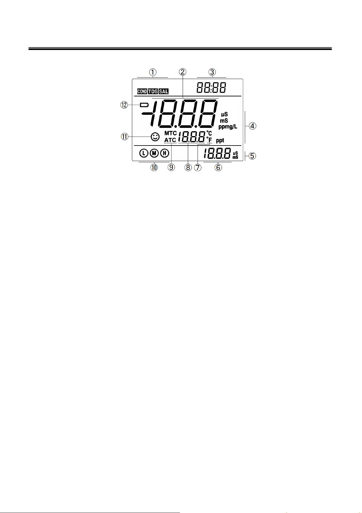
3.1. LCD display:
1 — Measuring mode icons
○
Diagram-1 LCD screen
2 — Measurements
○
3 — Prompts
○
4 —Measurement Units
○
5 —Conductivity calibration Units
○
6 — Conductivity calibration value and prompts
○
7 —Temperature units
○
8 — Temperature value and prompts
○
9 — Temperature compensation state icons
○
ATC — automatic temperature compensation,
MTC — manual temperature compensation
10 — Calibration indication icon
○
11 — Stable reading indication icon
○
12 — Low battery icon, when this icon appears, please renew the battery
○
3
Page 6
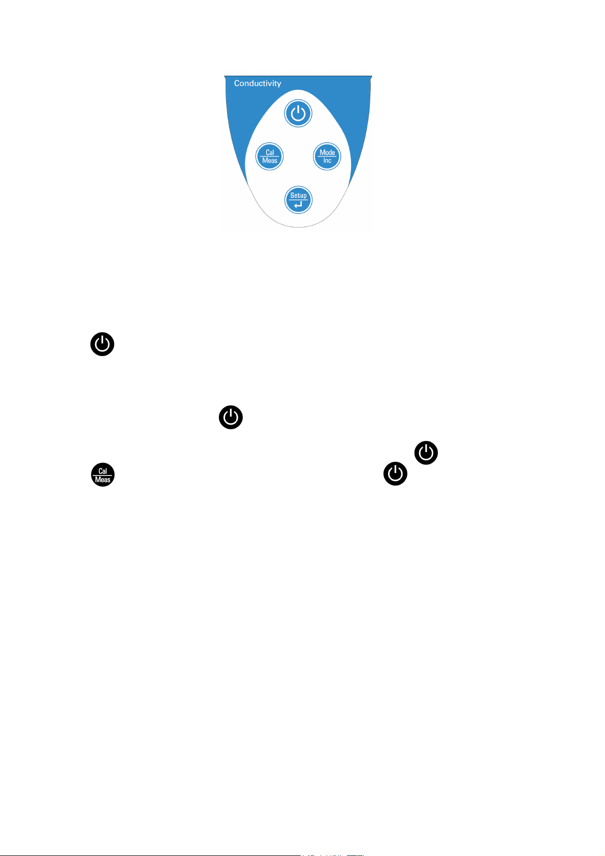
3.2. Keypad functions
3.2.1. Keypad operations
Diagram-2 Keypad panel
Short press: <1.5 seconds , Long press: >1.5 seconds.
3.2.2. Turn on the meter
Press to turn on the meter: LCD full display → display some parameters setting content→ display
the last measuring mode before turning off.
3.2.3. Turn off the meter
In the measurement mode, press and hold for 2 seconds to turn off the meter.
Note: In the calibration mode or the parameter set-up mode, pressing is invalid. Please
Press key to return to the measurement mode, then press to turn off the meter.
4
Page 7

Chart -1 Keypad operations and functions
Keypad Operations Functions
Short press
● In the power-off mode, press this key to turn on the meter
● In the measurement mode, press and hold this key for 2 seconds to
Long press
turn off the meter.
● In the measurement mode, press this key to select measurement
mode: → →
● In the mode of manual temperature compensation (MTC), when
press and hold this key, the temperature value flashes, then press
Short/long press
this key again to change the temperature value (only one
direction), and press to confirm
● In the parameter set-up mode, press this key to change the serial
number of the main menu and the submenu (only one direction)
● In the submenu mode, press this key to change parameters and
set-up (only one direction)
● In the measurement mode, press this key to enter in the calibration
mode
Short press
● In the calibration mode or the parameter set-up mode, press this
key to return to the measurement mode
● In the measurement mode, press this key to enter in the parameter
set-up main menu
Short press
● In the calibration mode, press this key to make calibration
● In the parameter set-up mode, press this key to select programs
3.3. Meter sockets
The meter is with BNC and RCA sockets, which are protected by grey rubber caps. (As showed in
Table-2)
Chart-2- Meter sockets
Photos Descriptions
BNC socket (Left) — for conductivity probe;
RCA socket (Middle) — for temperature probe.
3.4. Auto power-off
The meter will be automatically power-off if nothing is done for 20 minutes. In the parameter setting
menu P6.8, user can set up to turn on or turn off this function.
5
Page 8

4. Conductivity Measurement
4.1. Conductivity probe information
4.1.1. Matching conductivity probe
The meter includes one plastic conductivity probe (Model 2301T-F, K=1.0). With built-in temperature
sensor, the meter can realize automatic temperature compensation. BNC plug of the probe is connected
to the meter’s conductivity socket while RCA plug is connected to the temperature socket. When the
probe is submerged in solution, stir the solution briefly to eliminate the air bubbles and in this way, a
stable measurement will be reached fast.
4.1.2. Conductivity probe constant
The meter can use with conductivity probes with three constants: K=0.1, K=1.0 and K=10.0. Please refer
to chart-3 for the measuring range. Set up constant in menu P2.1 and refer to details in clause 5.3.
Chart – 3 Probe constant and measuring range
Range
Conductivity probe
<20 μS/cm
K=0.1 cm
-1
0.5 μS/cm~100 mS/cm
K=1.0 cm-1 K=10 cm-1
>100mS/cm
constant
Standard solution 84μS/cm 84 μS/cm 1413 μS/cm 12.88 mS/cm 111.9 mS/cm
4.2. Conductivity calibration related information
4.2.1. Conductivity calibration solutions
The meter uses standard series of conductivity solution. The meter can recognize the standard solution
automatically and perform 1 to 4 point calibration. The calibration icons at the bottom left of LCD screen
is corresponding to four built-in standard values. See chart – 4:
Chart – 4 Conductivity standard solution series
Calibration indication icons Calibration solution series Measuring range
84 μS/cm 0-200 μS/cm
1413 μS/cm 200-2,000 μS/cm
12.88 mS/cm 2-20 mS/cm
111.9 mS/cm 20-200 mS/cm
4.2.2. Calibration intervals
(a) The meter is calibrated before leaving the factory and can generally be used right out of the box.
(b) Normally, performing calibration once a month is recommended.
(c) For high accuracy measurement or larger temperature deviation from the reference temperature
(25°C), performing calibration once a week is recommended.
(d) Use conductivity standard solution to check the probe. Perform calibration if the error is big.
6
Page 9

(e) When use a new probe for the first time, or the meter has restored to factory default setting, 3-point or
4-point calibration is recommended. For everyday use, standard solution closer to the sample solution
can be chosen to perform 1- point or 2-point calibration. For example: 1413 μS/cm standard solution is
suitable for measuring range 0-2,000 μS/cm.
4.2.3 1-point and multi-point calibration
If 1-point calibration is preformed after 3-point or 4-point calibration, the previous calibration value in the
same range will be replaced, meanwhile, the meter will show the calibration indication icon of this point,
other two calibration indication icons will be deleted, but the chip will reserve the last calibration data. All
calibration data will be deleted after restoring to factory default, and restore to theory value. When
perform multi-point calibration, the calibration solution should be chosen from low to high concentration
in order to avoid contamination of standard solution in low concentration.
4.2.4. Reference temperature
Factory set reference temperature is 25°C. Other reference temperature can also be set within the range
15°C – 30°C. Set up reference temperature in menu P2.5 and see details in clause 5.3.
4.2.5. Temperature coefficient
Factory set temperature compensation coefficient of the meter is 1.9%. However, the conductivity
temperature coefficient is different from that of varous kinds of solution and concentration. Please refer
to chart – 5 and the data collected during testing and set up the parameter in menu P2.6. See details in
clause 5.3.
Note: When the temperature compensation coefficient is set to 0.00 , meaning no temperature
compensation, the measurment value will be based on the current temperature.
Chart -5 Temperature compensation coefficient of certain solutions
Solution Temperature compensation coefficient
NaCl solution 2.12%/°C
5% NaOH solution 1.72%/°C
Dilute ammonia solution 1.88%/°C
10% hydrochloric acid solution 1.32%/°C
5% sulfuric acid solution 0.96%/°C
4.2.6. Avoid contamination of standard solution
Conductivity standard solution has no buffer. Please avoid being contaminated during usage. Before
submerging the probe in standard solution, please wash the probe and allow it dry. Please do not use
the same cup of conductivity standard solution frequently, especially for standard solution of low
concentration 84μS/cm. The contaminated standard solution will affect accuracy of measurements.
4.3. Conductivity meter calibration (take standard solution 1413μS/cm as an example)
4.3.1. Rinse the probe in pure water, allow it to dry, then wash it with a small amount of standard solution
7
Page 10

and submerge it in standard solution. Stir the solution briefly and allow it to stay in the solution until a
stable reading is reached.
4.3.2. Press key to enter into the calibration mode.
“std” icon will blink at the top right of the screen, while scanning and locking
process of calibration solution will be showed at the bottom right.
Er 2 appears if press key before the value is locked. See Chart – 7.
4.3.3. When the meter locks 1413 μS, stable icon will appear on LCD
screen. Press key to calibrate the meter. End icon appears after calibration
is done. The meter returns to the measurement mode and LCD shows
icon at the bottom left. See Diagram – 3 for the above calibration process.
4.3.4. If exit from calibration mode without confirmation, press key to
return to the measurement mode without calibration.
4.3.5. For multi-point calibration, please repeat clause 4.3.1-4.3.3 until all
the calibration is done. The meter can perform calibration in the same calibration
solution repeatedly until the value displayed is stable and repeatable.
4.4 Relationship among TDS, salinity and conductivity
4.4.1 Press key to switch the measurement mode:
→ →
Diagram- 3
4.4.2 TDS and conductivity is linear related. The conversion
coefficient is 0.40~1.00 which can be adjusted in parameter setting P2.7.
Factory default setting is 0.71 and please refer to clause 5.3 for details. Salinity and conductivity are
interrelated. The calculation formula has been put in the program of the meter. So the meter only needs
to be calibrated in conductivity mode, then switch to TDS and salinity mode.
4.4.3 Customers can adjust TDS conversion coefficient in parameter setting P2.7 according to testing
data and experience. Please refer to chart-6 for some frequently-used conductivity and TDS conversion
coefficients. Just for your reference.
Chart -6 Conversion coefficient between conductivity and TDS
Conductivity of solution TDS conversion coefficient
0~100 μS/cm 0.60
100~1,000 μS/cm 0.71
1~10 mS/cm 0.81
10~100 mS/cm 0.94
8
Page 11

4.5. Customer-defined calibration (take 10.50μS/cm standard solution as an example)
4.5.1. Select CUS in parameter setting P2.2 (please refer to clause 5.3 for customer-defined calibration)
and the meter enters into customer-defined calibration mode. Press , LCD shows blinking CUS at
the top right, indicating that the meter enters into customer-defined calibration.
4.5.2.
Rinse the probe in pure water, allow it to dry, and submerge it in 10.50 μS/cm standard solution.
Stir the solution briefly and allow it to stay in the solution until a stable reading is reached and icon
appears on LCD.
4.5.3. Press key, the measuring value blinks. Press key to adjust the measuring value to 10.50
μS/cm, and press key to calibrate the meter. After the calibration is done, the meter will return to
measurement mode. In conductivity mode with customer-defined calibration, the probe calibration
indication icons will not appear on the screen.
Note: If use conductivity electrode without temperature sensor, meaning manual temperature
compensation (MTC) is adopted, the temperature value blinks when press key, press
key to adjust the temperature value, and when press key, conductivity value blinks.
4.5.4. Only 1-point calibration for customer-defined calibration. The conductivity value of the
customer-defined solution is at a fixed temperature. There is no regulation of temperature coefficient and
reference temperature. The meter has to perform calibration and measurement at the same temperature
to avoid large error. The meter cannot recognize customer-defined calibration solution.
4.6. Sample Measurement
4.6.1. Rinse conductivity probe in pure water, allow it to dry, and submerge it in the sample solution. Stir
the solution briefly and allow it to stay in the sample solution until a stable reading is reached and
icon appears on LCD screen. The reading got is the conductivity value of the solution.
4.6.2. Press key to switch TDS value or salinity value.
4.6.3. During the process of calibration and measurement, the meter has self-diagnosis functions,
indicating the relative information as showed in chart – 7.
9
Page 12

Chart – 7 Self-diagnostic information of conductivity measurement mode
Icons
Self-diagnostic information
Check up
1. Check if the conductivity calibration
Wrong conductivity calibration solution
or exceed recognition range of the
meter
solution is accurate.
2.Check if the connection between meter and
probe is good.
3.Check if the probe is failed.
Press key when measuring value
Press key when icon appears
is not stable during calibration.
During calibration, the measuring value
is not stable for ≥3min.
1.Shake the probe to eliminate bubbles
in probe head.
2.Replace conductivity probe with a new one.
4.6.4 Factory default setting
For factory default setting, please refer to parameter setting P2.8 (Clause 5.3). With this function, all
calibration data will be deleted and the meter will restore to the theory value. Some function settings will
be restored to the original value (refer to appendix -1). When calibration or measurement fails, please
restore the meter to factory default setting and then perform re-calibration or measurement. Please note
that once the meter is restore to factory default setting, all the data deleted will not be retrievable.
4.7. Conductivity probe maintenance
4.7.1. Always keep the conductivity probe clean. Before taking a measurement, rinse the probe in pure
water and then rinse it in the sample solution. When submerge the probe in solution, stir the solution
briefly to eliminate air bubbles and allow it to stay in the solution until a stable reading is reached. For
dry- stored conductivity probe should be soaked in pure water for 5-10 minutes before measuring. Rinse
the probe in pure water after measuring.
4.7.2. The sensitive rod of Model 2301T-F conductivity probe is coated with platinum black to minimize
probe polarization and expand measuring range. Do not scrub platinum black. Only stir the probe in pure
water to avoid damage of the platinum black coating. Clean organic stain on the probe in warm water
with detergent, or alcohol.
4.7.3. If the probe coated with platinum black is found unworkable, immerse it in 10% nitric acid solution
or 10% hydrochloric acid solution for 2 minutes, then rinse the probe in pure water and take
measurement after that. If the probe still does not work, re-coat platinum black, or replace with a new
conductivity probe.
10
Page 13

m
m
0
d
c
e
2
6
m
f
a
p
t
r
4
D
r
a
n
s
k
4
t
o
r
2
u
P
n
→
u
e
PPPPPPP
P
r
o
6
s
m
p
c
r
e
s
T
e
t
a
o
o
p
2
e
g
a
m
r
e
s
f
pa
r
s
a
o
t
t
:
n
g
5. Para
5.1. Main
In the mea
P2.0→P6.
P2.0: Con
P6.0: Basi
5.2. Subm
5.2.1. In P
press
5.2.2. In P
see
Main
eter setti
enu
surement
. Please re
uctivity par
parameter
nu
.0 mode,
key to swi
.0 mode, p
Diagram–
menu of pa
ng
ode, press
er to diagr
meter setti
setting me
ress
ch among
ess
.
ameter set
iagram –
key t
m – 4
ng menu,
u.
key to ente
ubmenu: P
ey to enter
ing
Main men
enter in
in subme
.1→P2.2
in submen
and subm
2.0, then p
u P2.1 of c
P2.5→P2.
P6.1 of ba
Submenu
2.1 Select
2.2 Select
2.5 Select
2.6 Select t
compen
2.7 Select
2.8 Restor
Submenu
6.1 Select
6.8 Autom
nu of para
ess t
nductivity
→P2.7→P
ic paramet
of Cond.
robe const
onductivity
eference te
mperature
ation facto
DS coeffici
to factory
of basic pa
emperature
tic power-o
eter settin
switch to
arameter
.8, see Di
r setting,
rameter se
nt
standard s
p.
nt
et
ameter set
unit
f setup
main menu
etting, the
gram– 4.
tin
lution
ing
11
Page 14
u
t
.
t
P
e
o
a
→
r
e
d
r
e
r
e
r
t
r
o
o
s
o
n
m
r
t
f
m
r
e
C
-
e
n
a
e
m
n
e
m
o
r
Y
s
0
e
r
s
t
s
e
a
e
s
a
4
f
s
e
(
e
r
k
s
1
o
m
o
e
e
o
m
0
o
t
m
o
o
m
o
s
r
e
2
d
2
e
m
0
p
o
o
o
e
e
o
r
.
r
y
t
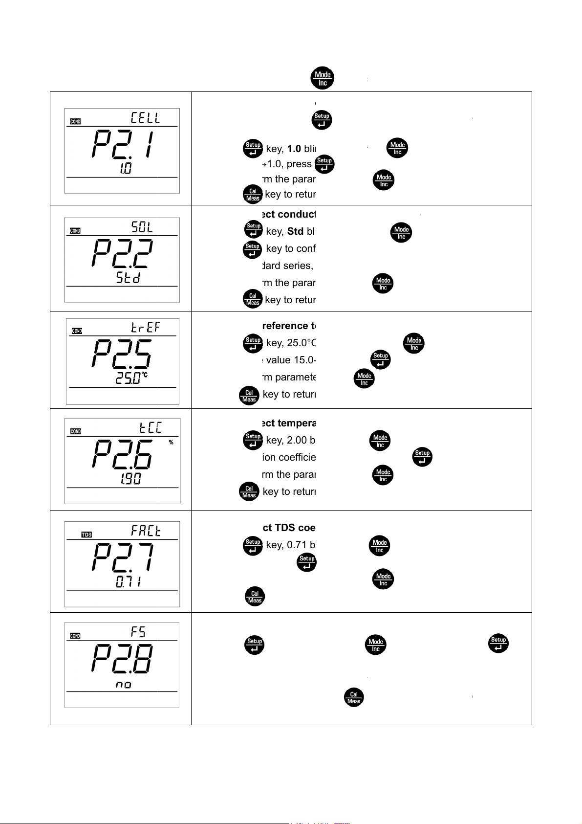
5.3. Cond
ctivity parameter set
1.
2.
3.
ing subme
P2.1 – Sel
In P2.0 m
the left Di
Press
10.0→0.1
After confi
press
nu (press
ct probe c
de, press
gram.
key, 1.0 bli
1.0, press
m the para
key to retu
key to
nstant (1.
key to
ks, then p
key to
eter, pres
n to the me
witch)
-10.0-0.1)
nter in P2.
ess ke
confirm.
key t
asurement
mode, pl
y to select
enter in P
ode.
ase refer t
.2 mode, o
P2.2 – Sel
1.
Press
Press
Std – Stan
2.
After confi
press
P2
5 – Select
1.
Press
emperatur
2.
After confi
press
P2.6 – Sel
1.
Press
compensat
2.
After confi
press
ct conduc
key, Std bl
key to con
ard series,
m the para
key to retu
reference t
key, 25.0°
value 15.0
m paramet
key to retur
ct temper
key, 2.00 b
ion coeffici
m the para
key to retur
ivity stand
inks, then p
irm.
CUS – cus
eter, pres
n to the me
mperatur
blinks, the
30.0, press
r, press
to the me
ture comp
links, press
nt 0.00 – 9.
eter, pres
to the me
ard soluti
ress k
omer-defin
key t
asurement
(15.0°C-3
n press
key t
key to en
surement
nsation c
key to
99, press
key t
surement
n (Standar
y to select
d solution
enter in P
ode.
.0°C)
key to sel
confirm.
er in P2.6
ode.
efficient (
select tem
key to c
enter in m
ode.
-CUS)
CUS→Sad
.5 mode, o
ct
ode, or
.00-9.99%)
erature
nfirm.
de P2.7 or
P2.7 –Sele
1.
Press
coefficien
After confi
2.
press
2.8 – Rest
1.
Press
to confirm
No – Do n
2.
If do not
ct TDS co
key, 0.71 b
, press
m the para
key to retu
re to fact
key, No bli
, the meter
t restore,
elect Yes,
fficient (0.
links, press
key to con
eter, pres
rn to the m
ry setting
ks, press
eturn to th
es – Resto
press
0~1.00)
key to
irm.
key t
asurement
No – Yes)
key, Ye
measurem
e to factory
ey to retu
select TDS
enter in m
mode.
blinks, pr
ent mode.
setting.
n to the m
de P2.8 or
ss ke
asuremen
mode.
12
Page 15

b P
t
o
O
d
g
m
m
m
e
u
r
n
u
n
p
m
n
e
s
m
f
e
a
s
m
O
o
e
5.4. Basic
parameter setting su
1.
2.
3.
1.
2.
menu
6.1. Selec
In P6.0 mo
he left Dia
Press
Press
When para
r press
P
6.8 – Auto
Press
Press
n – turn on
After confir
measurem
t temperat
e, press
ram.
key, °C blin
key to confi
eter is co
key to ret
atic powe
key, On bli
key to confi
automatic
the para
nt mode.
re unit (°C
key to e
ks, then pr
m.
firmed, pre
rn to the
-off setup
ks, press
rm.
ower-off, O
eter, press
—°F).
ter in P6.1
ss key
s key
easuremen
(On-Off)
key to s
f – turn off
key to
mode, plea
to select→℉
to enter in
t mode.
lect Off→
utomatic p
return to th
e refer to
℃
ode P6.8
n.
wer-off.
13
Page 16

6. Meter Kits
No. Include Quantity
6.1 C100 Handheld Cond. Meter 1
6.2 2301T-F plastic conductivity probe 1
6.3 AA Battery 3
6.4 Screw driver 1
6.5 Instruction Manual 1
6.6 Quick manual 1
14
Page 17

7. Warranty
7.1 For three years since the date of purchasing, under regular service condition, we warrant that the
instrument (probe is not included) will be repaired, replaced parts or product free of charge if the meter
doesn’t work well due to quality defects.
7.2 This warranty does not apply to defects resulting from incorrect usage, improper maintenance or
repair.
15
Page 18

Appendix I:
Parameter setting & Factory default setting
Modes Prompts Parameter setting items
P2.1 Select probe constant
Select conductivity
standard solution
Select reference
temperature
Adjust temperature
compensation
P2.0
Cond.
P2.2
P2.5
P2.6
coefficient
P2.7 Adjust TDS coefficient
Restore to factory
default setting
P6.0
P2.8
P6.1 Select temperature unit
Basic
Parameters
P6.8
Automatic Power-off
setup
Code and
Abbr.
Description
1.0-10.0-0.1
Std-CUS
Restore to
factory
default
1.0
Std
15~30 °C 25 °C
0.00~9.99 2.00
0.40~1.00 0.71
No-Yes
No
/ °C-°F -
On-Off -
16
Page 19

Appendix II: Code Symbol & Abbreviation Glossary
Modes Prompts
P2.1
P2.2
P2.5
P2.0
Conductivity
P2.6
P2.7
P2.8
P6.1
P6.0
Basic parameters
P6.8
Code and
abbreviation
/
In English Description
Cell Constant Cell
Calibration solution Calibration solution
Reference temperature Reference temperature
Temperature
compensation coefficient
Adjust TDS coefficient Adjust TDS coefficient
Factory default setting Factory default setting
/
Automatic Power-off Automatic Power-off
Standard Standard
Temperature
compensation coefficient
Others
Customer-defined Customer-defined
OFF OFF
ON ON
NO NO
YES YES
17
Page 20

18
 Loading...