

Page 1
OPERATING MANUA L
VARIABLE-SPEED
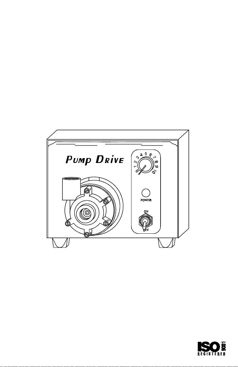
PUMP DRIVE
Model Nos.
900-1103 900-1104
900-1105 900-1106
Shown with optional 7 GPM Centrifugal Pump
The Pump Drive provides variable speed drive
capability for MICROPUMP® pumps.
Barnant Co.
28W092 Commercial Ave.
Barrington, Illinois U.S.A. 60010-2392
(847) 381-7050
(847) 381-7053 (Fax)
800-637-3739
www.barnant.com
e-mail: barnant@barnant.com
A-1299-0678
Edition 01
Page 2

Page 3

TABLE OF CONTENTS
Title Page
SAFETY PRECAUTIONS .................................................................ii
INTRODUCTION.............................................................................. 1
DESCRIPTION................................................................................. 2
INSTALLATION/SETUP ................................................................... 3
OPERATION .................................................................................... 3
ON/OFF Control .......................................................................... 3
Speed Control.............................................................................. 3
TROUBLESHOOTING & MAINTENANCE....................................... 4
Troubleshooting ........................................................................... 4
Cleaning ...................................................................................... 4
Replacement Parts ...................................................................... 4
Motor Brush Check/Replacement................................................ 5
SPECIFICATIONS ........................................................................... 6
WARRANTY..................................................................................... 8
PRODUCT RETURN ........................................................................ 8
TECHNICAL ASSISTANCE ............................................................. 8
i
Page 4

SAFETY PRECAUTIONS
DANGER: High voltages exist and are accessible in
the Pump Drive. Use extreme caution
when servicing internal components.
WARNING: PRODUCT USE LIMITATION
These products are not designed for , nor intended for use in
patient connected applications; including, b ut not limited to ,
medical and dental use, and accordingly has not been submitted for FDA approval.
MICROPUMP - Reg TM Micropump Inc., a division of Idex Corp.
TEFLON - Reg TM E.I. Du Pont de Nemours & Co.
Trademarks bearing the ® symbol in this publication are registered in the U.S. and in other countries.
ii
Page 5

INTRODUCTION
The instructions in this manual are task oriented to allow easy access
to the desired information. Figure 1 provides summarized information
on all controls to the Pump Drives. This manual contains complete
information on installing and setting up the Pump Drives, as well as
operating and servicing at the user level. The following chart provides
basic information on models covered in this manual.
Drive
Catalog Output Flow Power
Number rpm rate Requirement*
900-1103 50 to 5000 2.5 - 5450 mL/min 90 to 130 VAC
900-1104 190 to 260 VAC
900-1105 90 to 9000 0 - 7.0 gpm 90 to 130 VAC
900-1106 200 to 260 VAC
*AC voltages can be either 50-60 Hz.
The Pump Drives contain the pump drive motor and motor controls in
one compact unit. MICROPUMP pump heads are attached directly to
the motor which is accessible from the front panel. In addition, these
drives incorporate the following features:
• Permanently lubricated motor for continuous duty
• Motors are soft-starting
• Speed control over a 100:1 range
• Pumps are magnetically coupled to motor
• Stackable
• IP22 rating per IEC 529
• Replaceable Motor Brushes
(purchase pump head separately)
(with provided pump head)
900-1105 and 900-1106 are supplied with a centrifugal pump attached.
1
Page 6

DESCRIPTION
These electronic drives are self-contained compact units which include
a drive motor and all operating controls (see Figure 1). These drives
are especially designed for magnetically coupled pumps.
The 900-1103 and 900-1104 drives come without a pump head. It will
accept all MICROPUMP pump heads with standard mounting canisters. The pump heads can be easily mounted to the motor that is
accessible from the front panel. High and low speed versions are available covering a wide range of flo w rates.
able pump heads and performance information.
Note: Gear pumps should not be operated above 5000 rpm.
The 900-1105 and 900-1106 drives come with a 7-GPM Centrifugal
Pump head mounted on it. The pump head has 3/8 in NPT(F) inlet and
1/4 in NPT(F) outlet ports.
The solid-state speed control circuitry offers excellent speed regulation even with line v oltage and load v ariations. A PO WER indicator on
the front panel illuminates whenever the ON/OFF switch is in the ON
position. Pump drive speed can be manually controlled over a 100:1
range with the front panel mounted potentiometer. “Soft-start” and
smooth gradual acceleration to speed setting is provided when line
power switching.
Contact your dealer for a vail-
Figure 1
2
Page 7

INSTALLATION/SETUP
Unpack the Pump Drive and retain all packing material until proper
product operation has been verified.
The Pump Drive rests on four vibration isolator f eet f or placement on a
bench, desk, or table. It is supplied with a power cord attached.
1. If applicable, attach the MICROPUMP pump head.
2. Check that the ON/OFF Switch is in the down (OFF) position.
3. Connect the A C power cord on the rear panel to the A C power source.
4. Set the speed control to zero.
5. Install the pump belo w the lev el of the supply liquid. The liquid must
be under atmospheric conditions.
6. This completes the basic setup.
Note: To prevent damage to pump; do not restrict pump inlet or run the
pump dry .
OPERATION
Operation of the Pump Drive has been simplified requiring only two
controls, the ON/OFF Control and the Speed Control (see Figure 1).
The operation of each of these controls is explained below. When operating the drive, allow approximately 20 minutes for warm-up speed
drift to become minimal.
ON/OFF Control
The ON/OFF Control is used for turning power ON or OFF. When the
control is in the down position, power is OFF and the green POWER
light is not lit.
Speed Control
The Speed Control setting determines the rpm of the pump and therefore, the flow r ate . Depending on the model the maximum speeds will
be either 5000 or 9000. Rotating the Speed Control clockwise increases
speed linearly .
3
Page 8

TROUBLESHOOTING & MAINTENANCE
Troubleshooting
SYMPTOM CAUSE REMEDY
The motor does not
rotate, when the ON/
OFF switch (Figure 1) is
moved up. P ower
indicator does not glow.
Erratic variations
in speed.
No power.
Worn motor brushes.
1. Chec k that Pump Drive
is plugged into a power
source.
2. Return for servicing.
See “Motor Brush
Replacement Procedure. ”
Cleaning
Keep the Pump Drive enclosure clean by wiping down with a mild
detergent. Never immerse or use excess fluid.
Replacement Parts
The following parts are user replaceable.
Part
Description Number
Brushes (set of 2) 7520-04
Cordset - USA (115 V units) 50001-68
Cordset - Australia (230 V units) 50001-60
Cordset - Denmark (230 V units) 50001-62
Cordset - India (230 V units) 50001-64
Cordset - Israel (230 V units) 50001-66
Cordset - European (230 V units) 50001-70
Cordset - British (230 V units) 50001-72
Cordset - Swiss (230 V units) 50001-74
Cordset - Italian (230 V units) 50001-76
Cordset - USA (230 V units) 50001-78
Fuse - T 1.6 A, 250 V (230 V units) 77500-11
Contact your dealer if you have service needs.
4
Page 9

Motor Brush Check/Replacement
Note: Brushes should be checked every 6 months, or approximately
500 operating hours or if erratic operation occurs.
DANGER: High voltages exist and are accessible in
the Console Drive. Use extreme caution
when servicing internal components.
1. Place the Power switch in the off position.
2. Disconnect the AC power input line cord from the AC receptacle.
3. Remove the four screws from each side of the housing and lift off
the housing.
4. Carefully unscrew each brush cap on opposite sides of the motor
(Figure 2). Withdraw the brush, and examine it for wear.
Figure 2. Typical Brush Replacement
Note: Replace both brushes, if either brush is less than 0.300 in
(7.6 mm) long from base to point.
5. Insert brushes and install brush cap on each side of motor.
6. Install housing and secure with the four screws on each side.
7. Connect the AC power input line cord to the AC receptacle.
5
Page 10

SPECIFICATIONS
Output:
Speed, Max.:
Model 900-1103, -1104 5000 rpm
Model 900-1105, -1106 9000 rpm
Speed, Min.:
Model 900-1103, -1104 50 rpm
Model 900-1105, -1106 90 rpm
Torque ouput, Maximum: 12 oz-in
Flow-range:
Model 900-1103, -1104 2.5 to 5450 mL/min
(purchase pump head
separately)
Model 900-1105, -1106 0 to 7.0 gpm
(with provided pump head)
Adjustment ranges: Clockwise Motor Rotation
Speed regulation, line: ±1%
Speed regulation, load: ±2%
Speed regulation, warm-up drift: ±10%
Duty Cycle: Continuous
Input:
Supply Voltage Limits: 90 to 130 VAC or
200 - 260 VAC
Frequency: 50/60 Hz
Current, max:
115 V 2.3A
230 V 1.4A
Installation Category: Installation Category II per
IEC 664 (local level—
appliances, portable
equipment, etc...)
6
Page 11

Construction:
Dimensions: 7 in-L x 7 in-W x 5 in-H
(17.8 x 17.8 x 12.7 cm)
Weight (Drive only): 8 pounds (3.6 kg)
Enclosure Rating: IP22 per IEC529
Centrifugal Pump
(900-1105, -1106): Flow rate: 7 gpm
Maximum fluid temperature:
121°C
Maximum system pressure:
200 psi
Differential pressure: 10 psi
Wetted parts: 316 SS and
TEFLON® PTFE
Environment:
Temperature, Operating: 0°C to 40°C
Temperature, Storage: –45°C to 60°C
Humidity: 10% to 90%
noncondensing
Altitude: less than 2000 m
Pollution Degree: Pollution Degree 2 per
IEC 664
(Indoor usage—lab, office)
Chemical Resistance: Exposed Material is paint,
steel and aluminum.
7
Page 12

WARRANTY
The Manufacturer warr ants this product to be free from significant deviations from published specifications. If repair or adjustment is necessary within the warranty period, the problem will be corrected at no
charge if it is not due to misuse or abuse on your part as determined by
the Manufacturer. Repair costs outside the warranty period, or those
resulting from product misuse or abuse, may be invoiced to you.
The warranty period for this product is noted on the Warranty
Card.
PRODUCT RETURN
To limit charges and delays, contact the seller or Manufacturer for
authorization and shipping instructions before returning the product,
either within or outside of the warranty period. When returning the
product, please state the reason for the return. For your protection,
pack the product carefully and insure it against possible damage or
loss. Any damages resulting from improper packaging are your
responsibility.
TECHNICAL ASSISTANCE
If you have any questions about the use of this product, contact the
Manufacturer or authorized seller.
Printed in U.S.A.
8
011196
 Loading...