

Page 1
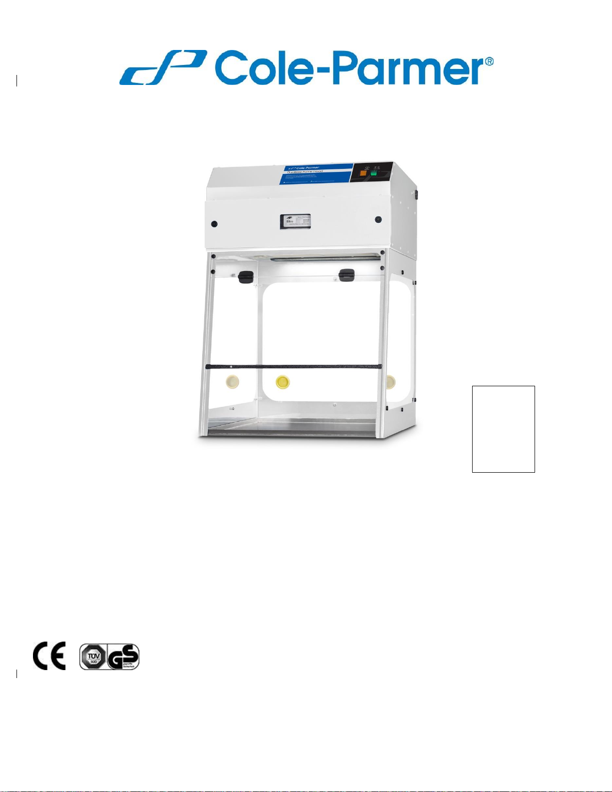
Cole-Parmer® Basic
Series Ductless Fume
Hoods
USER OPERATION MANUAL
l Revision No.: PURAIR-BASICSERIES.V4.2020
pictured: Model P5-XT with optional
velomete
Specifications are subject to change without notice or obligation.
78900-00
78900-01
78900-02
78900-03
78900-04
78900-05
Page 2

USER OPERATION MANUAL
Table of Contents
Safety Warnings / Symbols ................................................................................................................................. 3
Limitation of Liability ........................................................................................................................................... 3
Warranty ............................................................................................................................................................. 4
I. Product Information ................................................................................................................................ 5
II. Unpacking Your Cabinet ........................................................................................................................ 5
2.1 Step-By-Step Procedure ................................................................................................................................ 5
2.2 Packaging Contents ...................................................................................................................................... 6
III. Installing Your Cabinet ......................................................................................................................... 7
3.1 Choosing a Suitable Location ........................................................................................................................ 7
3.2 Environmental / Electrical Conditions ........................................................................................................... 7
3.3 Installing Your Cabinet .................................................................................................................................. 8
3.4 Set Up ........................................................................................................................................................... 9
3.5 Performance Validation / Certification .........................................................................................................16
3.6 Importance of Performance Validation / Certification ..................................................................................16
3.7 Disclaimer ....................................................................................................................................................16
IV. Operating Your Cabinet ....................................................................................................................... 17
4.1 Control System ............................................................................................................................................. 17
4.2 Cabinet Operating Procedure ......................................................................................................................18
V. Monitoring ....................................................................................................................................................19
5 .1 General ........................................................................................................................................................19
5.2 Manual Monitoring ........................................................................................................................................19
VI. Maintenance .............................................................................................................................................. 20
6 .1 General ....................................................................................................................................................... 20
6.2 General Cleaning ........................................................................................................................................ 20
6.3 Pre-Filters ................................................................................................................................................... 20
6.4 Lights .......................................................................................................................................................... 20
6.5 Airflow ......................................................................................................................................................... 20
6.6 Calibration Instructions ................................................................................................................................ 21
6.7 Changing Out Filters ................................................................................................................................... 22
6.8 Airflow Adjustment ...................................................................................................................................... 22
6.9 Maintenance Schedule ............................................................................................................................... 23
6.10 User Monthly Maintenance Schedule ....................................................................................................... 23
6.1 1 Fault Finding ............................................................................................................................................. 24
6.12 Component Changing ............................................................................................................................... 25
VII. Filter Information ............................................................................................................................... 26
7 .1 Filter Descriptions ....................................................................................................................................... 26
VIII. Product Specifications .......................................................................................................................... 27
Page 3
3 \ USER OPERATION MANUAL: Cole-Parmer Basic Ductless Fume Hood Series
Safety Warnings
• Read all instructions before proceeding and observe the installation procedure and
environmental/electrical requirements.
• Anyone working with, on or around this equipment should read this manual. Failure to read,
understand and follow the instructions given in this documentation may result in damage to
to the unit, injury to operating personnel and/or poor equipment performance.
• Any internal adjustment, modification or maintenance to this equipment must be undertaken by
qualified service personnel.
• The use of any hazardous material in the cabinet must be monitored by an industrial hygienist,
safety officer or some other suitably qualified individual.
• Explosive or inflammable substances should never be used in the cabinet unless a qualified safety
professional has evaluated the risk involved.
• If chemical, radiological or other non-microbiological hazards are being used in the cabinet,
additional protective measures should be taken. Additionally, the operation should be monitored by
a suitably trained individual.
• If the equipment is used in a manner not specified by this manual, the protection provided by this
equipment may be impaired.
Symbols
Warning of hazardous area or situation
Warning of dangerous electric voltage
Limitation of Liability
The disposal and/or emission of substances used in connection with this cabinet may be governed by various
local regulations. Familiarization and compliance with any such regulations are the sole responsibility of the
users of the cabinet. Cole-Parmer’s liability is limited with respect to user compliance with such regulations.
At the end of your product and accessories life, it must not be discarded as domestic waste. Ref:
EU Directive 2012/19/EU on Waste Electrical and Electronic Equipment Directive (WEEE). Please
contact your distributor / supplier for further information. For end users outside of the EU consult
applicable regulations.
Page 4

4 \ USER OPERATION MANUAL: Cole-Parmer Basic Ductless Fume Hood Series
Warranty
The manufacturer agrees to correct for the original user of the product, either by repair (using new or refurbished parts), or
at the manufacturer’s election, by replacement (with a new or refurbished product), any defects in material or workmanship
which develop during the warranty period. The standard warranty is twelve (12) months after delivery of the product for NonConsumable and Electrical parts, excluding Filters and other Consumables. In the event of replacement, the replacement
unit will be warranted for the remainder of the original warranty period or ninety (90) days, whichever is longer. For purposes
of this limited warranty, “refurbished” means a product or part that has been returned to its original specifications. In the
event of a defect, these are your exclusive remedies.
If the product should require service, contact the manufacturer’s/supplier’s office for instructions. When return of the product
is necessary, a return authorization number is assigned and the product should be shipped, transportation charges pre-paid,
in either its original packaging or packaging affording an equal degree of protection to the indicated service center. To
ensure
prompt handling, the return authorization number must be placed on the outside of the package. A detailed explanation of
the defect should be enclosed with the item. The warranty shall not apply if the defect or malfunction was caused by
accident, neglect, unreasonable use, improper service, acts of God, modification by any party other than Cole-Parmer, or
other causes not arising out of defects in material or workmanship.
EXCLUSION OF IMPLIED WARRANTIES. THERE ARE NO WARRANTIES, EXPRESSED OR IMPLIED, INCLUDING,
BUT NOT LIMITED TO, THOSE OF MERCHANTABILITY OR FITNESS FOR A PARTICULAR PURPOSE WHICH
EXTEND BEYOND THE DESCRIPTION AND PERIOD AS STATED IN THE OPERATOR’S MANUAL INCLUDED WITH
EACH PRODUCT. LIMITATION ON DAMAGES. THE MANUFACTURER’S SOLE OBLIGATION UNDER THE WARRANTY
IS LIMITED TO THE REPAIR OR REPLACEMENT OF A DEFECTIVE PRODUCT AND THE MANUFACTURER SHALL
NOT, IN ANY EVENT, BE LIABLE FOR ANY INCIDENTAL OR CONSEQUENTIAL DAMAGES OF ANY KIND RESULTING
FROM USE OR POSSESSION OF THIS PRODUCT.
Some states do not allow: (A) limitations on how long an implied warranty lasts; or (B) the exclusion or limitation of
incidental or consequential damages, so the above limitations or exclusions may not apply to you. This warranty gives you
specific legal rights and you may have other rights that vary from state to state.
Page 5

5 \ USER OPERATION MANUAL: Cole-Parmer Basic Ductless Fume Hood Series
I . Product Information
The Cole-Parmer® Basic Series ductless fume hoods are a series of high efficiency products designed to protect
the user and the environment from hazardous vapors generated on the work surface. At the heart of the ColeParmer fume hood product line is the innovative Filtration Technology that creates a safe work environment
over the widest range of applications in the industry.
Visit our website for Cole-Parmer Basic Series ductless fume hood specifications.
II . Unpacking Your Cabinet
This chapter aims to provide relevant information on how to handle the cabinet properly upon receipt. Failure to
follow these instructions may damage the cabinet. We strongly advise you to read this chapter carefully before
proceeding further.
2.1 Step-By-Step Procedure
1. Inspecting the Crate, Pallet, Boxes.
» Upon receipt of your new cabinet, inspect all cartons. If there is any visible damage to the exterior please
refer to Damaged Freight Claim Information on our website.
2. Moving the Pallet.
» The pallet is designed to protect our cabinet from any foreseeable circumstances. However, excessive
impact onto the boxes or pallet may also damage the cabinet. Prevent any direct impact or hitting to the
pallet when moving.
» When lifting the pallet, always ensure that the floor jack or mechanical lift truck has fully entered under
the pallet in order to achieve stability. Failure to do so will increase the risk of the pallet falling off the
floor jack or mechanical lift truck during handling. Please use a suitable extension bar when necessary.
3. Opening the Boxes.
» If you did not receive one or more of the parts listed on the packing checklist, or if any of the items are
damaged, please refer to the Damaged Freight Claim Information on our website.
Page 6

6 \ USER OPERATION MANUAL: Cole-Parmer Basic Ductless Fume Hood Series
4. Removing the Packaging Material.
» The cabinet is protected by extruded polystyrene foam, cardboard and/or shrink-wrap.
» If you find any damage during this stage of unpacking please refer to the Damaged Freight Claim Information
on our website.
» We recommend leaving the cabinet secured with straps to the pallet until the cabinet is located in its
approximate final position to facilitate ease and safety in handling.
Note: Choosing the best location for your cabinet in order to achieve optimum operating performance
is determined by a number of factors. Please refer to the next chapter for some guidelines.
5. Moving the Cabinet.
» When lifting the pallet with the cabinet, always ensure that the floor jack or mechanical lift truck has fully
entered under the pallet. This is to increase the stability of the cabinet and reduce the risk of the cabinet
falling down. Please use a suitable extension bar when necessary. During the moving of the cabinet,
ensure there is enough distance between the supports of the pallet and the ground. Dragging the pallet
against the ground will damage the pallet and possibly your new cabinet.
» When removing cabinet from pallet or placing cabinet onto pallet, use at least two people.
6. Removing the Strapping.
» Remove the strapping by cutting it at a safe position to prevent any scratching the surface of your new
cabinet.
» Do not discard the packaging material for your cabinet until you have checked all of the components, installed
and tested the unit.
7. Lifting the Cabinet.
» The cabinet can be lifted in two sections: The HEAD unit and ENCLOSURE.
» Install the cabinet on the existing work surface or Cole-Parmer support stand (if ordered).
Note:
» When installing the cabinet onto an existing work surface, ensure that the structure can safely support the
combined weight of the cabinet and any related equipment. Some modifications to the work surface may be
necessary.
» The work surface should be smooth, non-porous and resistant to the disinfectants and chemicals used
in conjunction with the cabinet.
2.2 Packaging Contents
The following items are included with your manual:
• Test Report
In case this manual and/or test report is lost or misplaced, the factory retains a copy in our files. A replacement
copy can be obtained by contacting Cole-Parmer and providing the cabinet model, serial number and a brief
description of the information desired.
Page 7

7 \ USER OPERATION MANUAL: Cole-Parmer Basic Ductless Fume Hood Series
III . Installing Your Cabinet
3.1 Choosing a Suitable Location
Location impacts the nature and extent of external airflow disturbances, which may affect performance of the
cabinet when it is exposed to these disturbances.
When installing the cabinet, it should be located as far away as possible from sources of airflow disturbance and
in an orientation which optimally shields the airflow of the cabinet from all external airflow disturbances. Please
note that the cabinet should not be placed close to another cabinet.
Please follow these guidelines when choosing a suitable location for your cabinet:
• The location must be far away from:
» Personnel traffic flows.
» Air vents (in and out).
» Doors and windows.
» Any other sources of disruptive air currents or air drafts.
• If drafts or other disruptive air currents exceed the face velocity of the filter, the potential exists for
contaminated air to enter the work zone of the cabinet.
• A minimum distance of 50 cm (20 in.) to the top of the ceiling is recommended for blower changing
purposes.
• A clearance of 183 cm (6 ft) in front of the cabinet is strongly advised in order to maintain proper airflow.
• Please permit adequate space for cleaning behind the cabinet.
3.2 Environmental / Electrical Conditions
The equipment is designed to be safe for at least the following conditions:
» Indoor use.
» Altitude < 2,000 m (6,562 ft).
» Temperature range 5ºC to 40ºC (41ºF to 104ºF) ambient.
» Relative humidity <80% up to 31ºC (88ºF) decreasing to <50% at 40ºC (104ºF).
» UL Installation Category II.
» UL Pollution Degree 2.
» Continuous operation.
» Electrical supply tolerance of –10% / +10%.
» 120VAC, 60Hz, 10A or 230VAC, 50Hz, 5A.
» Fuse: 250V, 10A, Time Lag for 120VAC or Fuse: 250V, 5A, Time Lag for 230VAC.
» Always ensure unit is connected to a reliable and properly grounded receptacle.
» Appliance inlet on this device is the disconnect device; appliance should not be positioned so that it is difficult
to operate it.
Page 8

8 \ USER OPERATION MANUAL: Cole-Parmer Basic Ductless Fume Hood Series
Power Cord:
» 1) For units intended to be operated at 120 volts (North America): Use a UL-listed and CSA-certified cord
set consisting of a minimum 18 AWG, Type SVT or SJT, three-conductor cord, a maximum of 15 feet in
length and a parallel blade, grounding-type attachment plug rated 15 amperes, 125 volts.
» 2) For units intended to be operated at 230 volts: Use a cord set with a grounding-type attachment plug. The
cord set should have the appropriate safety approvals for the country in which the equipment will be installed.
3.3 Installing Your Cabinet
1. Please refer to Unpacking Your Cabinet - page 5.
2. Inspect your cabinet carefully. Should you find any defect please contact customer service.
3. Peel off any protective masking that was left on the cabinet during manufacturing.
4. Wipe down the interior and exterior of the cabinet with water or a mild household detergent.
5. Connect cabinet to the main power supply and turn on the blower. Each cabinet requires its own dedicated
13A (230V) or 15A (115V) power outlet which should not be shared with other appliances.
WARNING! Do not move the cabinet without observing the following precautions:
• Observe the necessary precautions when relocating the cabinet, as it is heavy.
• Warning - Tipping Hazard. Pushing high up on the unit may cause system to tip over. Be careful when
moving. Move with assistance only.
Page 9
9 \ USER OPERATION MANUAL: Cole-Parmer Basic Ductless Fume Hood Series
3.4 Set Up
Your Cole-Parmer product is shipped in two parts. The following instructions and photos (shown is 78900-02)
explain how to:
Assemble the base “enclosure” and place the head unit (fan and controls) on top:
• Fit the main filter and the pre-filter.
• Fit the optional airflow meter.
• Adjust the fan-speed/airflow control.
• Adjust the “low airflow alarm”.
Prior to beginning assembly, ensure the following:
1. Area is free of obstructions, tripping hazards, etc.
2. Ample clearance is available on sides and overhead.
3. Appropriate number of personnel are on hand: two people recommended.
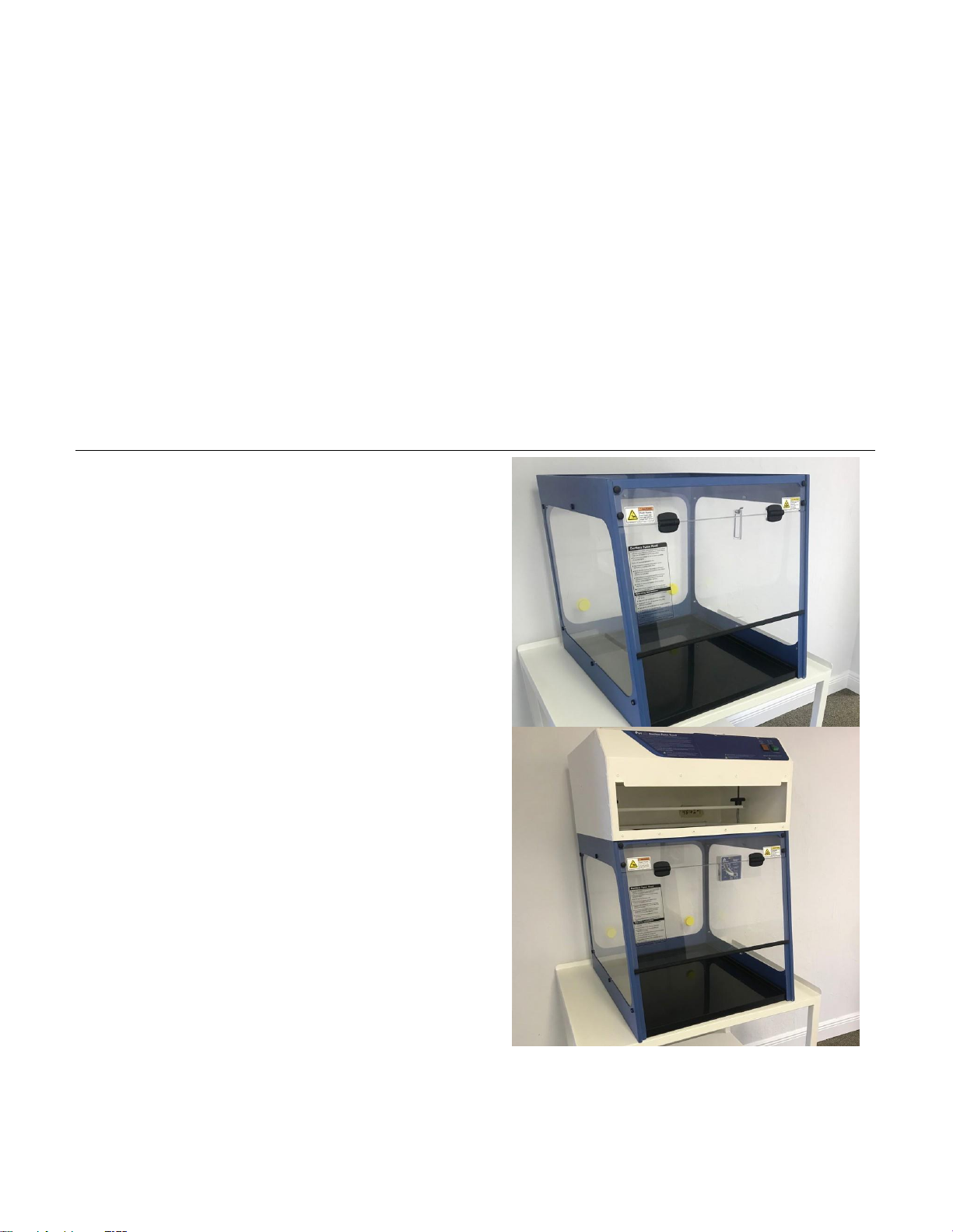
Fume Hood Assembly
1.
Unpack fume hood enclosure and set
on top of casework. In most cases the
enclosure is shipped fully assembled. If
unit is flat packed, please follow “flatpacked enclosure assembly sheet”.
2.
Unpack fan/filter module (aka head unit).
Lift head unit above and onto enclosure,
allowing airflow sensor/wire harness to
hang inside the enclosure.
Please allow a minimum clearance of 150 mm
(6 inches) between the right hand side of the unit
and any adjacent wall to allow the detachable power
supply cord to be disconnected from the power source.
Warning – Tipping Hazard. Please ensure
that all end rails of your unit are completely
on workbench and do not overhang the
workbench in any location.
Page 10

10 \ USER OPERATION MANUAL: Cole-Parmer Basic Ductless Fume Hood Series
Filter Installation
3. Pre-filter tray now inserts into four slots on the
sides of the cutout. Two tabs are bent at 90° to
allow it to hinge down into the workzone. Once
installed, lay the pre-filter on top of the tray.
4. Main filter now requires a painted metal "hat"
frame to be placed on top of the filter(s) before
lowering the clamping bar to secure them in
place.
5. Remove the filter access door using the barrel
key provided.
Page 11

11 \ USER OPERATION MANUAL: Cole-Parmer Basic Ductless Fume Hood Series
6. Insert the main filter, gasket side down,
centering it over the cutout.
7. If using two filter types, stack the second
filter on top of the first with the gasket side
down. Make sure the corners are squared
up to ensure proper installation.
8. Place the white metal hat frame on top of
the filter.
9. Rotate the black knobs inside the
compartment to lower the clamping bar.
The filter gasket should compress and the
filters should not wiggle if you attempt to
pull/push on them.
Page 12

12 \ USER OPERATION MANUAL: Cole-Parmer Basic Ductless Fume Hood Series
10. Reinstall the filter door and secure the locks
using the barrel key.
Final Assembly
Monitair and Autocal Equipped Units
11. To install the airflow sensor, remove the clear
panel on the inner right sidewall. Open the
screw cap on the outside of
the enclosure, undo the screw and nut and set
aside. DO NOT DISCARD!
12. Remove any tape on the airflow sensor which is
used to protect the sensor wires. Install the
sensor by attaching to the enclosure with the
screw and nut.
13. If not already installed, slide the polypropylene
spill tray into the enclosure. The side with the
extended handle/lip should go toward the back
of the hood.
Warning - Once installed do not remove spill tray
from enclosure. Do not use tray like a drawer. Do
not push down, lean on or apply excessive force.
Tray is only intended to sit over existing work
surface.
Page 13

13 \ USER OPERATION MANUAL: Cole-Parmer Basic Ductless Fume Hood Series
14. Attach the power cord to the inlet on the right
side of the head unit and connect to
appropriate power source.
DWYER Equipped Units
15. Add airflow meter as follows:
o
Insert vane/film into the airflow meter.
a. Slide out vane holder from side of meter
(just below the screw).
b. Carefully remove vane from plastic bag
and cardboard envelope (two vanes are
enclosed, one is a spare). Hang the vane
by the wire in the two slots provided in
the vane holder.
c. Slide the vane holder back into the meter.
o
The enclosure design allows the airflow meter
to be fitted to either side of the enclosure as
required.
Ensure that the side not to be used has the airflow
opening covered by the supplied blanking plate.
The side to be used should have an open hole to
fit the meter.
Page 14

14 \ USER OPERATION MANUAL: Cole-Parmer Basic Ductless Fume Hood Series
o
Remove the attaching screw from the meter.
o
Push the screw into the screw hole from the outside
of the enclosure.
o
Align the meter to the screw from the inside of the
enclosure.
o
Tighten the screw to secure the meter in place.
NOTE: The meter is now ready to take readings. It is precalibrated. If the vane becomes damaged, it is easily
replaced with the spare vane. The vaneometer is
accurate to ± 5% of full scale from 0-100 fpm and ± 10%
from 100 fpm to 400 fpm. The permanent mounting
bracket provided in the box is not used.
16. Removable yellow caps are provided in the rear wall
of the enclosure to allow cables and hoses to be fed
inside of the enclosure as required; refit the yellow
caps when the holes are not in use.
17. To calibrate the “low airflow alarm ”(see Calibration -
page 25), use a small Phillips screwdriver to adjust
the screw inside the calibration port. NOTE:
Adjustment screw is made of nylon, so please use
care not to damage the screw.
Page 15

15 \ USER OPERATION MANUAL: Cole-Parmer Basic Ductless Fume Hood Series
Exhaust Plenum Installation
(RX and NANO Fume Hoods Only)
1. Place the plenum in the correct orientation on the
metal top panel of the fume hood.
2. Insert the provided self-tapping screws into each hole
in the plenum housing.
3. Use a drill with a nut driver to tighten down the
plenum.
Waste Chute Installation
(RX Fume Hoods Only)
1. Locate the blanking panel currently installed on the
side of the fume hood.
2. Remove the mounting screws in each corner of the
blanking panel and disconnect the panel from the
fume hood.
3. Align the waste chute on the outside of the fume
hoods, matching the mounting holes with the
existing holes in the side of the fume hood.
4. Insert the mounting screws and tighten down evenly
(screw heads can be oriented to the inside or outside
of the fume hood).
Balance Enclosure Assemly
(RX and NANO Fume Hoods Only)
1. Stand up the rear baffle; it will pivot from an attached
hinge located on the left and right side panels.
Page 16

16 \ USER OPERATION MANUAL: Cole-Parmer Basic Ductless Fume Hood Series
3.5 Performance Validation / Certification
After installation and prior to use, cabinet performance must be validated and certified to factory standards. The
following tests should be performed:
Airflow Velocity
The testing methods and equipment required are specified on the test report. It is recommended that these tests
be performed only by a qualified technician who is familiar with the methods and procedures for certifying these
types of cabinets.
3.6 Importance of Performance Validation / Certification
An airflow velocity value that falls below the value specified inside the test report will not provide adequate
operator protection.
3.7 Disclaimer
The performance of the cabinet, while rigorously evaluated at the factory, cannot be guaranteed after transit
and installation. Therefore the on-site testing is always recommended.
2. Align the tabs for the rear baffle into slots in the
top baffle keeping the 1/4 turn clips facing down.
This will support the rear portion of the top baffle
and keep the rear baffle in the upright position.
3. Secure top baffle with brackets on the left, right
and front sides.
4. Secure the baffle to the brackets using 1/4 turn
clips. They are accessed from the bottom side of
the baffle.
Page 17

17 \ USER OPERATION MANUAL: Cole-Parmer Basic Ductless Fume Hood Series
IV . Operating Your Cabinet
4.1 Control System
Basic Control Panel (Standard)
Main On / Off for Light and Fan
Press the switch up to turn on. The green indicator lamp will illuminate to confirm the power is on. The fan will start
and the internal task light unit will illuminate.
Low Airflow Alarm
The alarm status is displayed on the control panel. In normal operation the lamp will not illuminate. If the airflow
falls below the pre-set point, the lamp will illuminate red. This alarm may be tested and calibrated.
Page 18

18 \ USER OPERATION MANUAL: Cole-Parmer Basic Ductless Fume Hood Series
4.2 Cabinet Operating Procedure
• The fume hood should only be operated with the correct filter installed for the application. Refer to
Filter Information - page 27 for further information. The ductless fume cabinet must not be used for laboratory
work in which chemicals of different types are used that do not match the filter type or that the primary chemicals
and their byproducts are not known. The ductless fume cabinet should not be used for different chemical
processes where chemicals from the different processes could react in the filter.
• To start the system, apply power to the system and switch on the green power On/Off switch. The lights and fan
will automatically turn on.
• Check the airflow and the filter condition of the cabinet on a regular basis. This is covered in Maintenance -
page 21.
• Please note, filter blocks do not absorb carbon monoxide or hydrogen. Small quantities will not cause hazards
because of the large dilution factor from the amount of air passing through the cabinet and the retardation of the
chemical in the filter matrix.
• Cole-Parmer fume hoods have been designed to handle fumes and vapors given off during everyday
laboratory procedures. These will be at the parts per million (PPM) level in the air stream entering the filter
block. It is not recommended that large quantities of solvents or acids be used or boiled off in the cabinet.
• In the event of a large spillage in the cabinet, the amount of fumes entering the filter block may temporarily
reduce the efficiency of the filter. For this reason any major spillage must be cleared up immediately, preferably
using spillage absorption granules rather than paper, which may aggravate the evaporation of toxic fumes from
the spillage area.
• Following a major spillage, the filters must be changed, as the heat of wetting may reduce the efficiency of the
filter. After a period of stabilization, the old filters may be reused, providing they have not reached the
saturation level.
• The electrical equipment in the cabinet such as the lights and controls are not in the dirty air stream of the
system. The system should not be used in a flammable room atmosphere. Special modified cabinets can be
provided for use in these areas. Contact Cole-Parmer for further information on these applications.
• Operators should avoid sudden movements within the fume cabinet, such as rapid opening or closing of the
sash window, as this may cause temporary reversal of the airflow.
• The operators should maintain the normal safety equipment and procedures for dealing with hazardous chemicals.
WARNING!
» Do not use a gas flame (Bunsen burners) whenever possible, as it interferes with airflow.
» Do not change the original blower speed of the cabinet unless the change is required by a decrease in
measured air velocity. Adjustment should be made only by a qualified technician. Do not operate the cabinet
if fan fails to run.
» Minimize arm movement. Move arms in and out of the cabinet slowly to avoid disrupting cabinet airflow.
» Use absorbent pads on the work surface where appropriate to minimize splatter and aerosol generation in
case of spillage.
» Keep lids/covers on all containers, dishes or sample plates.
Page 19

19 \ USER OPERATION MANUAL: Cole-Parmer Basic Ductless Fume Hood Series
V . Monitoring
5.1 General
The purpose of the monitoring program is to ensure consistent reliability from the system. This is achieved by
checking the following:
» If the pre-filters become blocked, the velocity of the cabinet will begin to fall and will eventually cause the
airflow alarm to illuminate.
» Manual checking of the main filters by the use of a Gastec™ or Draeger™ test kit will confirm the condition of
the filters.
5.2 Manual Monitoring
Manual monitoring of the cabinet should be carried out at least once per year, as this will ensure the monitoring
systems are all within calibration and performing correctly.
Airflow Measurements
The inflow velocity of the hood should be checked with the sash at the correct operating height using an
anemometer such as a hot wire, vane anemometer or propeller type. Depending on the size of the cabinet, a
series of readings are to be taken at the front opening; these are to be recorded on a service sheet or system
log sheet.
Manual Filter Testing
The condition of the filter is to be checked using a Gastec or Draeger test kit. Boiling off a suitable chemical
normally used in the cabinet or a controlled release should challenge the filter. Examples can include alcohols,
toluene and trichloroethylene.
For testing acid filters (acid adsorbing) or multi combination layered filters incorporating an acid layer, use sulfur
dioxide gas (SO2) at 2 bubbles per second through water.
The readings should be below your Country’s Occupational Exposure Limit (see Filter Information - page 27).
The results are to be recorded on a service sheet or system log sheet.
If a significant amount of chemical is noted at the exhaust of the system, the main filters should be changed.
Page 20

20 \ USER OPERATION MANUAL: Cole-Parmer Basic Ductless Fume Hood Series
VI . Maintenance
6.1 General
In some countries it is mandatory to maintain written records of checks, tests and repairs carried out on safety
equipment. These records must be kept for 5 years. A full list of Occupational Exposure Limits should be obtained
from your safety officer.
Regular preventative maintenance on the cabinet will reduce the possibility of hazard to the operator and ensure
reliable performance from the cabinet.
WARNING! Before attempting inspection and repairs to the cabinet, please ensure main power to
the system has been removed and that the power lead has been removed. It should also be noted that
fume cabinets are sometimes used to contain and protect users of the cabinet from hazardous
or harmful substances. Before commencing this schedule it is important to ensure the cabinet is safe
to work on.
6.2 General Cleaning
Wipe down the unit with only soapy water.
6.3 Pre-Filters
Check condition and replace if required.
6.4 Lights
Ensure that the light diffuser is clean before switching the system on. Check that the light is in working condition.
6.5 Airflow
Check and record the inflow air velocity at the working aperture as follows: Using a calibrated hot wire or vane
anemometer or similar approved airflow meter, take a minimum of 5 readings across the fume cabinet aperture as
shown below. Calculate the average airflow, which should be greater than 0.5 m/sec or 100 fpm +/- 10%.
The readings should be recorded on the service sheet or system log.
Page 21

21 \ USER OPERATION MANUAL: Cole-Parmer Basic Ductless Fume Hood Series
6.6 Calibration Instructions
Testing the Low Airflow Alarm
» Ensure the fitted pre-filters are new. Switch on the cabinet; the red/amber neon should not be
illuminated.
» Switch the unit off. Block the pre-filter using paper or cardboard to permit airflow of <0.3 m/sec or 60 fpm.
» Switch the unit on. The red/amber neon should illuminate. If not, the calibration should be reset.
Calibration
The low airflow alarm operates using a differential pressure switch to detect a “high vacuum” situation when the
pre-filter is blocked or blocking up. The pressure switch is calibrated and tested prior to leaving our factory and
under normal circumstances will not require any adjustment.
» With the cabinet running and the pre-filter blocked as described above, locate the grey pressure switch
through the hole in the right hand sidewall. Adjustment is made by turning the small screw in the end of the
switch. (See Photograph #16 - page 14).
» Adjust the screw to make the alarm show. You may have to repeat these steps to ensure an accurate
setting has been achieved.
» Remove the blockage and restart the machine. The red/amber neon should not be illuminated.
Page 22

22 \ USER OPERATION MANUAL: Cole-Parmer Basic Ductless Fume Hood Series
6.7 Changing Out Filters
WARNING! Ensure persons removing filters are made aware of any potential hazards and that they are
provided with any necessary protective clothing and equipment.
Hazards associated with the removal and disposal of used filters will depend on the application of the hood. If
an activated carbon filter is used with hydrocarbon solvents, the filter will retain the solvents without loss, and
can be removed in the laboratory. The used filter should be sealed into a plastic bag prior to disposal,
preferably by incineration.
If the filter has contained any dangerous materials such as asbestos dust or radioactive chemicals,
operator protection is advised, including the use of a respirator. The used filters may require disposal by
a specialist company.
NOTE: CONSULT YOUR SAFETY OFFICER OR INDUSTRIAL HYGIENIST BEFORE REMOVING OR
DISPOSING ANY FILTERS.
Pre-Filters
The pre-filter is located below the main filter. Remove the perforated pre-filter tray. Remove the old pre-filter and
place it into a bag. Seal for disposal. Refit the new filter and refit the pre-filter tray.
Main Carbon / HEPA Filter
WARNING! Disconnect the power supply before removing filter access cover.
• Remove the front cover to gain access to the filter. Loosen the filter clamps. Lift the filter slightly to break
the seal and then withdraw the filter. Place the filter in a plastic bag. Seal the bag for disposal.
• Slide the new filter into position by pushing the filter fully into the module. Refit the front cover and lock it in
position.
• Please note, sometimes after new filters are fitted, it may be necessary to recalibrate the airflow system.
This procedure can be found in Calibration - page 21.
6.8 Airflow Adjustment
The speed controller on the cabinet can be accessed behind the main control panel.
Page 23

23 \ USER OPERATION MANUAL: Cole-Parmer Basic Ductless Fume Hood Series
6.9 Maintenance Schedule
Please follow the suggested maintenance schedule in order to maintain your Cole-Parmer cabinet at its
optimum performance.
Monthly
1. Using a damp cloth, clean the exterior surfaces of
the cabinet, particularly the front and top of the
cabinet, to remove any accumulated dust. When
needed use soap or other household mild
detergent.
Quarterly
1.
Replace pre-filters.
2.
All monthly activities.
Annually
1.
Replace all main HEPA or carbon filters.
2.
All quarterly activities.
Biannually
1.
Replace the fluorescent lamps.
2.
All annual activities.
6.10 User Monthly Maintenance Schedule
Model:
Year:
Serial Number:
Responsible Person:
Month
Clean Exterior Surface
Notes
By Whom
Jan
Feb
Mar
Apr
May
Jun
Jul
Aug
Sep
Oct
Nov
Dec
Page 24

24 \ USER OPERATION MANUAL: Cole-Parmer Basic Ductless Fume Hood Series
6.11 Fault Finding
WARNING! Before attempting any inspection or replacement of electrical components, always isolate
the cabinet from the main power supply and remove the power supply cable.
Fault
Check
Low Airflow Alarm
•
Check airflow at aperture
•
Check pre-filter is not blocked
•
Check fan is running
•
Recalibrate
Filter Saturated (Optional)
•
Check filter condition with Gastec or Draeger test kit
•
Check filter seal
•
Check filter is correct for application
•
Check date on filter
•
Replace all filters
Fan not Working
• Check inlet fuse
• Check any loose wires to terminal blocks
• Bypass speed controller; if fan works, replace speed controller
• Replace fan capacitor
• Replace fan
Page 25

25 \ USER OPERATION MANUAL: Cole-Parmer Basic Ductless Fume Hood Series
6.12 Component Changing
SHOULD ONLY BE CARRIED OUT BY TRAINED PERSONNEL
WARNING! Ensure main power supply has been removed prior to any work being carried out.
Light Units
To change a light unit, use the following instructions:
1. Ensure the power cord has been disconnected from the wall outlet.
2. Using the key supplied, unlock both ends of the blue cover door to
access filter compartment on head unit.
Page 26

26 \ USER OPERATION MANUAL: Cole-Parmer Basic Ductless Fume Hood Series
VII . Filter Information
Filter Types
Cole-Parmer offers different types of activated carbon and particulate filter media. These formulas can be
customized or layered into combinations to best suit your specific application. HEPA filters are available for
applications involving particulates and can be combined together with any of our activated carbon filters.
7.1 Filter Descriptions
Carbon Filter Organic Solvents
78900-13
Carbon Filter Acids Sulfur
78900-14
HEPA Filter Powder Particulate
78900-15
Carbon Filter Formaldehyde
78900-16
Carbon Filter Ammonia Amines
78900-17
6 Prefilters for Basic Ductless
78900-18
Page 27

27 \ USER OPERATION MANUAL: Cole-Parmer Basic Ductless Fume Hood Series
VIII. Product Specifications
Page 28

28 \ USER OPERATION MANUAL: Cole-Parmer Basic Ductless Fume Hood Series
Cole-Parmer
625 East Bunker Court
Vernon Hills, IL 60061-1844
Ph: 1-800-323-4340
Fax: 1-847-247-2929
www.coleparmer.com
info@coleparmer.com
78900Basic_rev_1.0
©2020 Cole-Parmer Instrument Company, LLC. All rights reserved.
 Loading...