

Page 1
© 04-08
Cole-Parmer Instrument Co.
625 East Bunker Court
Vernon Hills, Illinois U.S.A. 60061-1844
800-323-4340
fax: 847-247-2929
www.coleparmer.com
e-mail: techinfo@coleparmer.com
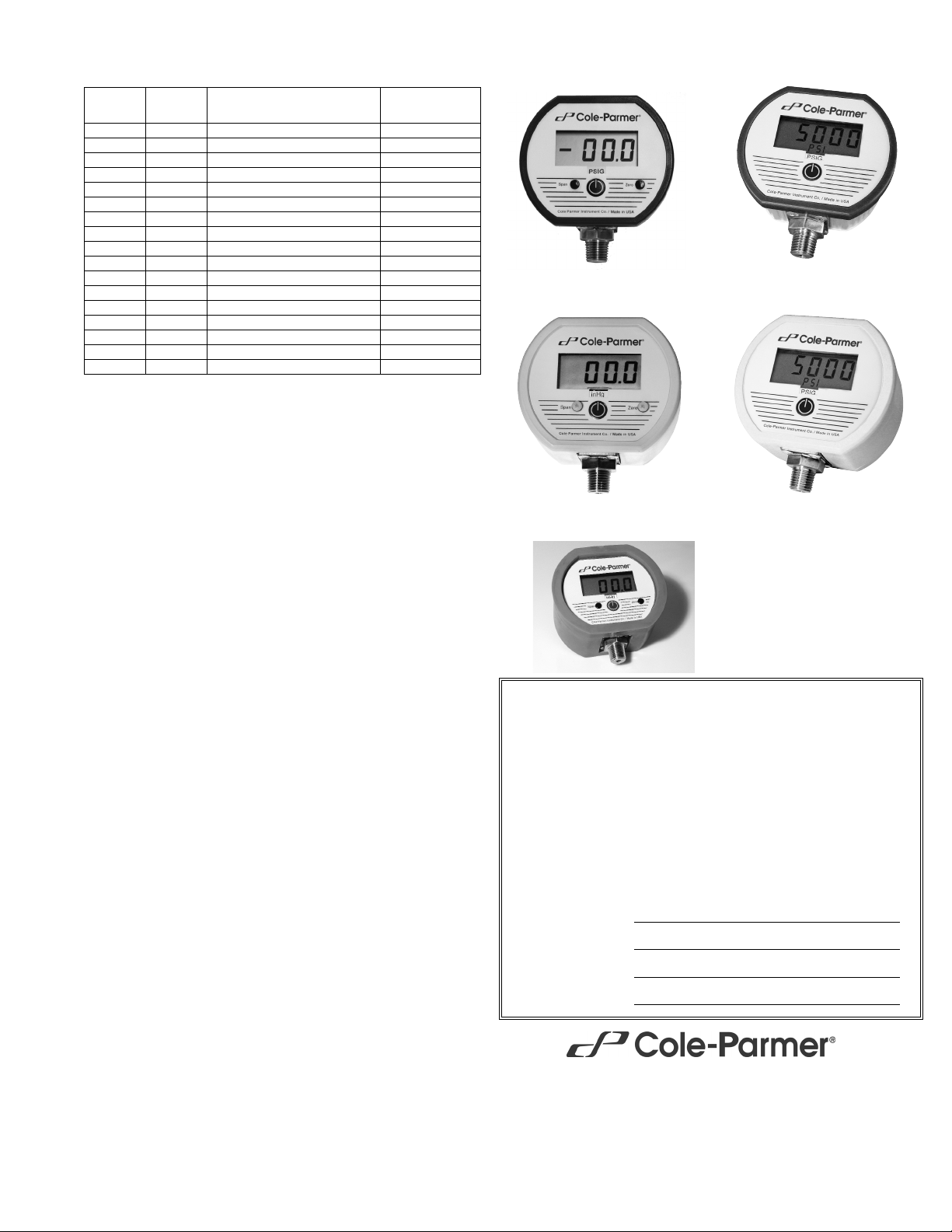
Cole-Parmer®Battery-Powered Digital Pressure Gauges
Accuracy
±0.25% of full scale ±1 least significant digit
Includes linearity, hysteresis, repeatability
Display
3 readings per second nominal display update rate
Ranges up to 1999: 31/2 digit LCD, 0.5" digit height
3000 psi, 5000 psi: 4
1
/2 digit LCD, 0.5" digit height,
lower alphanumeric display for engineering units
NEMA 4X models: Red LED backlight on whenever gauge is on
Controls
Ranges up to 1999
Front button turns gauge on/off
Front calibration potentiometers, non-interactive zero and span, ±10% range
3000 psi, 5000 psi ranges
Front button turns gauge on, starts auto shutoff timer, and provides zero function for gauge reference ranges
NEMA 4X models: Button activates backlighting for 1 minute while gauge is on
Internal calibration buttons, non-interactive zero and span, ±10% range
Batteries and Battery Life
Two AA alkaline
5 minute auto shutoff
Low battery symbol on display when batteries must be replaced
Standard models with ranges up to 1999: approx. 2500 hours
Standard models with 3000 psi, 5000 psi ranges: approx. 2000 hours
NEMA 4X models with backlit display and ranges up to 1999: approx. 180 hours
NEMA 4X models with backlit display, 3000 psi, 5000 psi ranges: approx. 150 to
1500 hours depending on backlight usage
Dimensions
Standard: 3.38" W x 2.88" H x 1.65" D housing
NEMA 4X: 3.5" W x 3.0" H x 2.0" D housing
Add approximately 0.75" to height for pressure fitting
Weight
Gauge: 9 ounces (approx)
Shipping weight: 1 pound (approx)
Material and Color
Standard: Extruded aluminum case, epoxy powder coated. Polycarbonate
cover, front and rear gaskets. Light gray body, light gray/blue front.
NEMA 4X: UV stabilized polycarbonate/ABS case, light gray color. Clear polycarbonate window to protect display. Gasketed rear cover, six captive stainless
steel screws.
Pressure/Vacuum Connection and Material
1
/4" NPT male, 316 stainless steel, compatible with most liquids and gases
Overpressure
3000 psig range and metric equivalents: 5000 psig
5000 psig range and metric equivalents: 7500 psig
3000 psi, 5000 psi: 112.5% out-of-range display
ii
– – – or ii–.–.–.–
All others 2 times rated pressure minimum
Burst Pressure
4 times rated pressure minimum or 10,000 psi, whichever is less
Environmental
Storage Temperature –40 to 203°F (–40 to 95°C)
Operating Temperature –4 to 185°F (–20 to 85°C)
Compensated Temperature 32 to 158°F (0 to 70°C)
68935-18
0 to 100.0 psig range
68935-32
0 to 5000 psig range
68936-95 Rubber Boot
Not for NEMA 4X models
Standard
Model no.
NEMA 4X
Model no.
Range Resolution
68935-00 68935-34 760 to 0 torr absolute 1 torr
68935-02 68935-36 0 to 30.0" Hg vacuum 0.1" Hg
68935-04 68935-38 0 to 3.00 psig 0.01 psig
68935-06 68935-40 0 to 5.00 psig 0.01 psig
68935-08 68935-42 –30.0" Hg vac. to 15.0 psig 0.1" Hg/0.1 psig
68935-10 68935-44 –15.0 to 15.0 psig 0.1 psig
68935-12 68935-46 0 to 15.00 psig 0.01 psig
68935-14 68935-48 0 to 30.0 psig 0.1 psig
68935-16 68935-50 –30.0" Hg vac. to 100.0 psig 0.1" Hg/0.1 psig
68935-18 68935-52 0 to 100.0 psig 0.1 psig
68935-20 68935-54 –30.0" Hg vac. to 199.9 psig 0.1" Hg/0.1 psig
68935-22 68935-56 0 to 199.9 psig 0.1 psig
68935-24 68935-58 0 to 300 psig 1 psig
68935-26 68935-60 0 to 500 psig 1 psig
68935-28 68935-62 0 to 1000 psig 1 psig
68935-30 68935-64 0 to 3000 psig 1 psig
68935-32 68935-66 0 to 5000 psig 1 psig
68935-36
0 to 30.0 inHg range, NEMA 4X
68935-66
0 to 5000 psig range, NEMA 4X
Certificate of Conformance
This product is manufactured according to applicable industry standards
and conforms to the manufacturer's engineering, production, calibration,
and quality standards.
This product conforms to the customer’s stated order requirements, including mechanical and electrical specifications, dimensions, physical item
identification (part number and serial number).
This product has been tested and calibrated to meet or exceed accuracy
specifications in effect at the time of manufacture using NIST traceable
standards maintained in accordance with ANSI/NCSL Z540-1 and ISO
10012.
This product is manufactured in the United States of America
Model
Serial Number
Date Purchased
Purchase Order
Page 2
Cole-Parmer Battery-Powered Digital Pressure Gauges
© 04-08
Installation and Precautions
Install or remove gauge using wrench on hex fitting only. Do not attempt to tighten by turning
housing or any other part of the gauge. Use fittings appropriate for the pressure range of the
gauge. Do not apply vacuum to gauges not designed for vacuum operation. Due to the hardness of 316 stainless steel, it is recommended that a thread sealant be used to ensure leakfree operation. NEVER insert objects into the gauge port or blow out with compressed air.
Permanent damage not covered by warranty will result to the sensor.
Operation – Ranges up to 1999
Press the round button on the front of the gauge to activate the display. The gauge will stay on
for approximately 5 minutes. The gauge can be shut off at any time by pressing the button
again. For models with display backlighting, the backlighting is on whenever the gauge is on.
Turn gauge off when not in use to conserve battery.
Operation – 3000 psi, 5000 psi Ranges
Press and hold the button for approximately 1 second. The full-scale range is indicated, display segments are tested, and the reading and units are displayed. The gauge will stay on for
5 minutes.
Power-Up with Zero (gauge reference models only)
1. Make absolutely certain no pressure is applied to the gauge. The gauge port should be
exposed to normal atmospheric pressure. Note that the zeroing function may only be activated at power-up and the stored zero correction is erased when the gauge is shut off.
2. Press and hold the button.
3. The full-scale range is indicated and the display segments are tested.
4. Continue to press the button until
o o o o
is displayed and then release the button. This indi-
cates that the gauge has been zeroed.
5. The actual pressure is displayed and the 5 minute auto shutoff timer starts.
Attempting to zero the gauge with pressure greater than approximately 3% of full-scale
applied will result in an error condition, and the display will alternately indicate
E r r 0
and the
actual measured pressure. The gauge must be powered down to reset the error condition.
Normal Operation
Following the start-up initialization, the display indicates the pressure reading and the engineering units. The 5 minute auto shutoff timer starts when the gauge is powered up or whenever the button is pushed.
If excessive vacuum is applied, the display will indicate
– E r r
until the vacuum is released.
Applying vacuum to a gauge designed for pressure may damage the sensor. If excessive pressure is applied (112.5% over range), an out-of-range indication of
I – – –
or
I –.–.–.–
will be
displayed depending on model.
Models with Display Backlighting
Display backlighting can be turned on by momentarily pressing the button whenever the gauge
is on. The backlighting will turn on for one minute and then automatically shut off. This also
restarts the auto shutoff timer.
Shut-Down
To shut off the gauge manually at any time, press and hold the button until the display indicates
O F F
(about 5 seconds) and then release.
The display indicates
O F F
five seconds prior to auto shutoff. The button can be pressed to
keep the gauge on. The auto shutoff and backlight timers are reset whenever the button is
pressed and released.
Calibration
All gauges are factory calibrated on NIST traceable calibration equipment. No calibration is
required before placing the gauge into service. Calibration equipment should be at least four
times more accurate than the gauge being calibrated. The calibration system must be able to
generate and measure pressure/vacuum over the full range of the gauge. A vacuum pump able
to produce a vacuum of 10 microns (0.01 torr or 10 millitorr) or lower is required for vacuum
and absolute gauges. It is good practice to install fresh batteries before calibrating batterypowered gauges. Allow the gauge to equalize to normal room temperature before calibration.
Calibration – Ranges up to 1999
Remove the calibration potentiometer covers on the front of the unit to access the zero and
span controls. Zero calibration must be done before span calibration.
Gauge reference Zero: The gauge port must be open to the ambient with no pressure or vacuum applied. Adjust the Zero control until the gauge reads zero with the minus (–) sign occasionally flashing. Gauges may be re-zeroed without affecting the span calibration.
Absolute reference Zero: Apply full vacuum to absolute reference gauges and adjust the Zero
control until the gauge reads zero with the minus (–) sign occasionally flashing. Gauges may
be re-zeroed without affecting the span calibration.
Span calibration: Apply pressure or vacuum depending on the type of gauge. Record readings
at three to five points over the range of gauge and adjust span control to minimize error and
meet specifications. Absolute reference gauges display atmospheric pressure when the gauge
port is open to the ambient and it is normal for the reading to fluctuate in response to normal
atmospheric pressure changes.
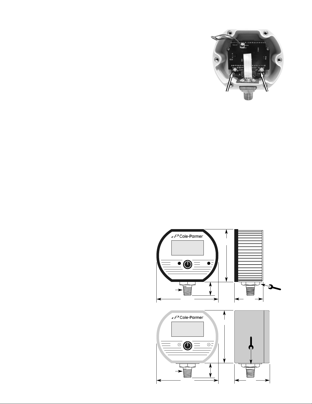
Calibration – 3000 psi, 5000 psi Ranges
Remove the screws on the back of the unit and remove cover and note the locations of the two
internal calibration buttons marked UP and DOWN. These buttons are disabled unless the
gauge is in calibration mode.
With the gauge off, press and hold the DOWN calibration button, and also press the front button to power up the gauge in calibration mode. The display first indicates the gauge’s full-scale
pressure range, tests all display segments, and then indicates
CAL
to indicate that the gauge
is in the calibration mode. Release all buttons.
The display will then indicate the current pressure reading. The gauge will remain in the calibration mode until powered down. While in the calibration mode the shutoff time, is disabled
and the calibration buttons are active.
Each press of the UP or DOWN button
makes a small correction, which may
not always be indicated on the digital
display. Press and hold the push button
for one second or longer to make larger
continuous corrections. The display of
the gauge being calibrated is adjusted to
match the calibrator’s setting or readout.
If the battery pack is unplugged during
calibration, calibration settings will not
be saved.
1. With the gauge port open to atmosphere, the character display will alternate between
ZERO
and
CAL
. Press the
UP and DOWN buttons to obtain a display
indication of zero.
2. Apply full-scale pressure. The character display will alternate between
+SPAN
and
CAL
.
Press the UP and DOWN buttons to obtain a display indication equal to full-scale pressure.
3. Apply 50% of full-scale pressure. The character display will alternate between
+MID
and
CAL
. Press the UP and DOWN buttons to obtain a display indication equal to 50% of full-scale
pressure.
4. Exit the calibration mode and save the calibration data by pressing and holding the front button until the display indicates
OFF
.
5. Verify pressure indications at 0%, 25%, 50%, 75%, and 100% of full scale.
6. Replace the rear cover and screws, taking care not to pinch the power leads between the
case and the rear cover.
Battery Replacement
A low battery indication will be shown in the upper left-hand corner of the display when the
battery voltage falls sufficiently. The battery should be replaced soon after the indicator comes
on or unreliable readings may result.
Remove the 6 Phillips head screws on the back of the unit.
Carefully remove batteries from the holders by lifting up the positive end of the battery (opposite the spring). Take care not to bend or distort the battery retention springs.
DO NOT discard the old battery into fire, any other sources of extreme heat, or in any other hazardous manner. Please consult local authorities if there is any question about proper disposal.
Always replace both batteries at the same time with high quality alkaline batteries. Observe
the polarity of the batteries when replacing them. The negative (flat) end of each battery should
be inserted first, and should face the spring in the battery holder.
Replace the back cover, including the rubber sealing gasket.
Dimensions
3000 psi and 5000 psi models use internal zero and span adjustments and do not have potentiometers.
1
/4 NPT
Cole-Parmer Instrument Co. / Made in USA
2.88"
3.38
"
0.75"
1.65
"
PSIG
Tur n
at hex
fitting
only
Span
Zero
31/2 digit or
4 digit display
1
/4 NPT
Cole-Parmer Instrument Co. / Made in USA
3.0"
3.5
"
0.75"
2.0
"
PSIG
Span
Zero
31/2 digit or
4 digit display
Tur n at
hex
fitting
only!
DOWN UP
NEMA 4X
Standard
Page 3
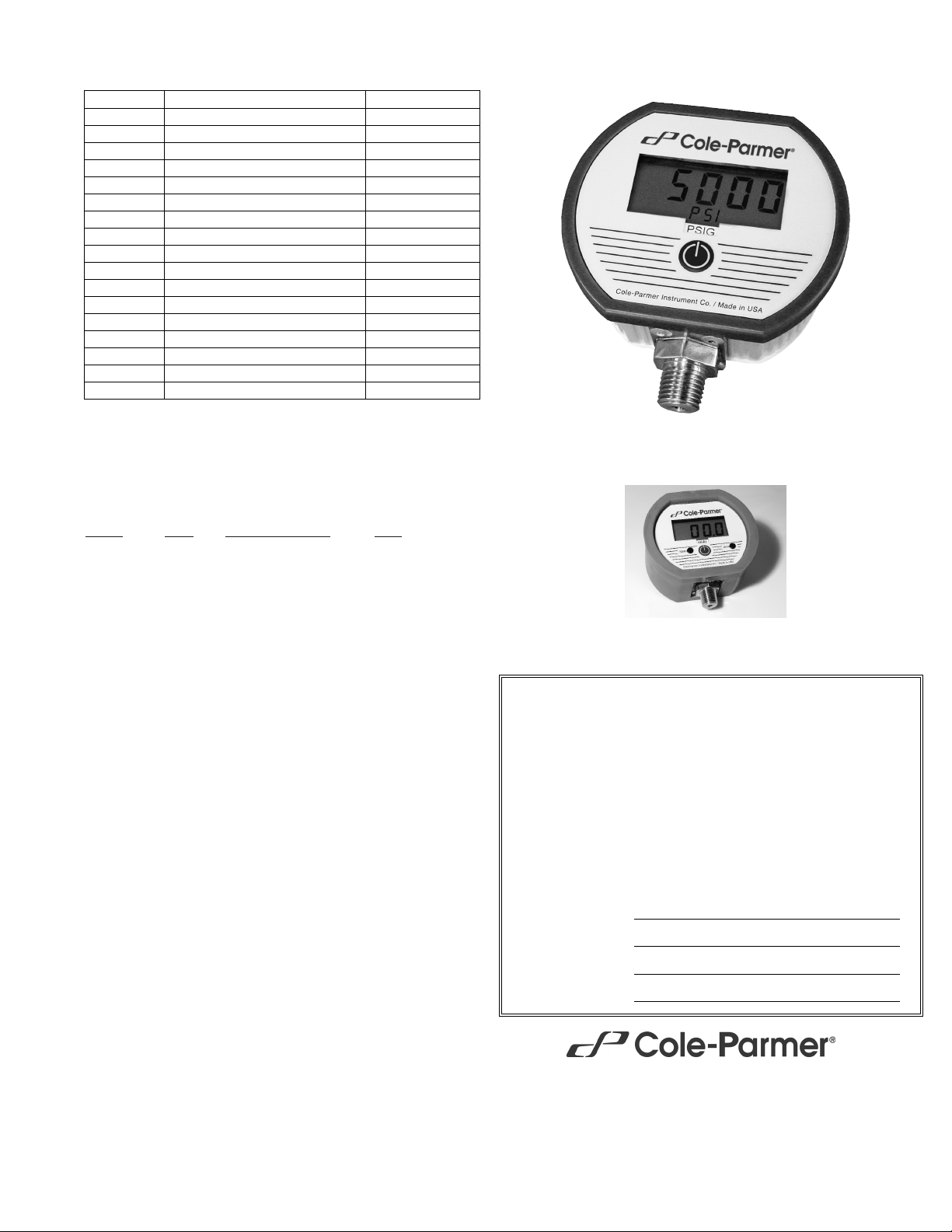
Cole-Parmer®Battery-Powered Gauges with Min/Max/Zero
68936-32
0 to 5000 psig range
Accuracy
Standard: ±0.25% of full scale ±1 least significant digit
Includes linearity, hysteresis, repeatability
Display
3 readings per second nominal display update rate
4 digit LCD, 0.5" H, 5 character 0.25" H alphanumeric lower display
Controls & Functions
Front button turns gauge on or off and cycles through functions
Calibration
Internal calibration buttons
Non-interactive zero, span, and linearity, ±10% range
Auto Shutoff
5 minutes
Batteries, Battery Life, Low Battery Indication
2 AA alkaline
Battery life approximately 2000 hours
Low battery symbol on display when batteries must be replaced
Dimensions
3.38" W x 2.88" H x 1.65" D housing
Add approximately 0.75" to height for pressure fitting
Weight
Gauge: 9 ounces (approx)
Shipping weight: 1 pound (approx)
Material & Color
Extruded aluminum case, light gray epoxy powder coated, ABS/ polycarbonate
bezel, front and rear gaskets, polycarbonate label
Pressure/Vacuum Connection Size & Material
1/4" NPT male
All wetted parts are 316 SS, compatible with most liquids and gases
Overpressure
3000 psig range and metric equivalents: 5000 psig
5000 psig range and metric equivalents: 7500 psig
All others: 2 x sensor pressure
112.5% out-of-range display: I – – – or I –.–.–.– depending on model
Burst Pressure
4 times sensor pressure rating, or 10,000 psi, whichever is less
Environmental
Storage Temperature –40 to 203°F (–40 to 95°C)
Operating Temperature –4 to 185°F (–20 to 85°C)
Compensated Temperature 32 to 158°F (0 to 70°C)
Model no. Range Resolution
68936-00 760.0 to 0 torr absolute 0.1 torr
68936-02 0 to 30.00" Hg vacuum 0.01" Hg
68936-04 0 to 3.000 psig 0.001 psig
68936-06 0 to 5.000 psig 0.001 psig
68936-08 –30.0" Hg vac. to 15.0 psig 0.1" Hg/0.1 psig
68936-10 –15.00 to 15.00 psig 0.01 psig
68936-12 0 to 15.00 psig 0.01 psig
68936-14 0 to 30.00 psig 0.01 psig
68936-16 –30.0" Hg vac. to 100.0 psig 0.1" Hg/0.1 psig
68936-18 0 to 100.0 psig 0.1 psig
68936-20 –30.0" Hg vac. to 200.0 psig 0.1" Hg/0.1 psig
68936-22 0 to 200.0 psig 0.1 psig
68936-24 0 to 300.0 psig 0.1 psig
68936-26 0 to 500.0 psig 0.1 psig
68936-28 0 to 1000 psig 1 psig
68936-30 0 to 3000 psig 1 psig
68936-32 0 to 5000 psig 1 psig
Function
Button Prompt
(Release Button)
Result
On Press 1 sec Gauge Range/Display Test Actual Pressure
One Touch Zero Press/hold
oooo
Zeroed Actual Pressure
Hi Reading Press/hold
HHII HHII
& max. reading
Lo Reading Press/hold
LLoo LLoo
& min. reading
Exit Hi/Lo Press/hold
AAPP
Actual Pressure
Clear Hi/Lo Press/hold
HHII/ LLOO/ AAPP ☞☞CCii
r
Actual Pressure
Clear Zero, Off Press/hold
HHII/ LLOO/ AAPP ☞☞CCiir☞☞ OOFFFF
Clear Zero, Gauge Off
© 04-08
Cole-Parmer Instrument Co.
625 East Bunker Court
Vernon Hills, Illinois U.S.A. 60061-1844
800-323-4340
fax: 847-247-2929
www.coleparmer.com
e-mail: techinfo@coleparmer.com
68936-95 Rubber Boot
Certificate of Conformance
This product is manufactured according to applicable industry standards
and conforms to the manufacturer's engineering, production, calibration,
and quality standards.
This product conforms to the customer’s stated order requirements, including mechanical and electrical specifications, dimensions, physical item
identification (part number and serial number).
This product has been tested and calibrated to meet or exceed accuracy
specifications in effect at the time of manufacture using NIST traceable
standards maintained in accordance with ANSI/NCSL Z540-1 and ISO
10012.
This product is manufactured in the United States of America
Model
Serial Number
Date Purchased
Purchase Order
Page 4

Installation and Precautions
Install or remove gauge using wrench on hex fitting only. Do not attempt to tighten by turning
housing or any other part of the gauge.
Use fittings appropriate for the pressure range of the gauge.
Do not apply vacuum to gauges not designed for vacuum operation.
Due to the hardness of 316 stainless steel, it is recommended that a thread sealant be used to
ensure leak-free operation.
NEVER insert objects into the gauge port or blow out with compressed air. Permanent damage
not covered by warranty will result to the sensor.
Power-Up
1. Press and hold the button for approximately 1 second.
2. The full-scale range is indicated and the display segments are tested.
3. The actual pressure and units are displayed.
Power-Up With Zero (gauge reference models only)
1. Be sure the gauge port is exposed to normal atmospheric pressure and no pressure is
applied. The zeroing function is only activated at each power-up and the stored zero correction
is erased when the gauge is shut off.
2. Press and hold the button.
3. The full-scale range is indicated and the display segments are tested.
4. Continue to press the button until
o o o o
is displayed and then release the button. This indi-
cates that the gauge has been zeroed.
5. The actual pressure is displayed.
Attempting to zero the gauge with pressure greater than approximately 3% of full-scale
applied will result in an error condition, and the display will alternately indicate
E r r 0
and the
actual measured pressure. The gauge must be powered down to reset the error condition.
Absolute reference gauges do not use the zero feature since they read atmospheric pressure
under normal conditions.
Normal Operation
Following the start-up initialization, the display indicates the pressure reading updated approximately 3 times per second. The auto shutoff timer starts when the gauge is powered up or
whenever the button is pushed.
If excessive vacuum is applied to a pressure-only gauge, the display will indicate
– E r r
until
the vacuum is released. Applying vacuum to a gauge designed for pressure may damage the
pressure sensor. If excessive pressure is applied (112.5% over range), an out-of-range indication of
I – – –
or
I –.–.–.–
will be displayed depending on model.
Minimum and Maximum Readings
Minimum and maximum readings are continuously stored and updated whenever gauge is on.
The stored readings can be manually cleared if desired. The high and low memory is also
cleared whenever the gauge is off.
Press and hold the button for about 1 second until HIis displayed. The maximum stored value
is displayed.
After
HI
is displayed, press and hold the button again for about 1 second until LOis displayed.
The minimum stored value is displayed.
After LOis displayed, press and hold the button again for about 1 second until AP(Applied
Pressure) is displayed. The high and low memory is not erased and the gauge returns to normal operation with the display indicating the current pressure.
Press and continue to hold the button until the display indicates
Clr Hi/Lo
(about 3 seconds
total) and then release the button. Both high and low values are cleared and the gauge returns
to the normal mode and displays the current pressure.
Shut-Down
To shut off the gauge manually at any time, press and hold the button until the display indicates
OFF
(about 5 seconds) and then release.
The display indicates
OFF
five seconds prior to auto shutoff. The button can be pressed to keep
the gauge on. The auto shutoff timers are reset whenever the button is pressed and released.
Turn gauge off when not in use to conserve battery life.
Calibration
All gauges are factory calibrated on NIST traceable calibration equipment. No calibration is
required before placing the gauge into service. Calibration equipment should be at least four
times more accurate than the gauge being calibrated. The calibration system must be able to
generate and measure pressure/vacuum over the full range of the gauge. A vacuum pump able
to produce a vacuum of 10 microns (0.01 torr or 10 millitorr) or lower is required for vacuum
and absolute gauges. It is good practice to install fresh batteries before calibrating batterypowered gauges. Allow the gauge to equalize to normal room temperature before calibration.
Remove the screws on the back of the unit and remove cover and note the locations of the two
internal calibration buttons marked UP and DOWN. These buttons are disabled unless the
gauge is in calibration mode.
With the gauge off, press and hold the DOWN calibration button, and also press the front button to power up the gauge in calibration mode. The display first indicates the gauge’s full-scale
pressure range, tests all display segments, and then indicates
CAL
to indicate that the gauge
is in the calibration mode. Release all buttons.
The display will then indicate the current pressure reading. The gauge will remain in the calibration mode until powered down. While in the calibration mode the shutoff timer is disabled.
Each press of the UP or DOWN button makes a small correction, which may not always be indicated on the digital display. Press and hold the push button for one second or longer to make
larger continuous corrections. The display of the gauge being calibrated is adjusted to match
the calibrator’s setting or readout.
If the battery pack is unplugged during calibration, calibration settings will not be saved.
Gauge Reference Gauges (3 Points)
1. With the gauge port open to atmosphere, the character display will alternate between
ZERO
and
CAL
. Press the UP and DOWN buttons to obtain a display indication of zero.
2. Apply full-scale pressure. The character display will alternate between
+SPAN
and
CAL
.
Press the UP and DOWN buttons to obtain a display indication equal to full-scale pressure.
3. Apply 50% of full-scale pressure. The character display will alternate between
+MID
and
CAL
. Press the UP and DOWN buttons to obtain a display indication equal to 50% of full-scale
pressure.
Absolute Reference Gauges (3 Points)
1. Apply full vacuum to the gauge. The character display will alternate between
ZERO
and
CAL
.
Press the UP and DOWN buttons to obtain a display indication of zero.
2. Apply full-scale pressure. The character display will alternate between
+SPAN
and
CAL
.
Press the UP and DOWN buttons to obtain a display indication equal to full-scale pressure.
3. Apply 50% of full-scale pressure. The character display will alternate between
+MID
and
CAL
. Press the UP and DOWN buttons to obtain a display indication equal to 50% of full-scale
pressure.
Bipolar (±) and –30inHg/15psig Compound Ranges (5 Points)
1. With the gauge port open to atmosphere, the character display will alternate between
ZERO
and
CAL
. Press the UP and DOWN buttons to obtain a display indication of zero.
2. Apply full-scale positive pressure. The character display will alternate between
+SPAN
and
CAL
. Press the UP and DOWN buttons to obtain a display indication equal to full-scale pressure.
3. Apply 50% of full-scale positive pressure. The character display will alternate between
+MID
and
CAL
. Press the UP and DOWN buttons to obtain a display indication equal to 50% of full-
scale pressure.
4. Apply full vacuum. The character display will alternate between
–SPAN
and
CAL
. Press the
UP and DOWN buttons to obtain a display indication equal to the full vacuum reading.
5. Apply 50% of the full-scale vacuum range (for example, –7.4 psi for a ±15 psi gauge). The
character display will alternate between
–MID
and
CAL
. Press the UP and DOWN buttons to
obtain a display indication equal to 50% of full-scale vacuum.
–30inHg/100psig and –30inHg/200psig Compound (4 Points)
1. With the gauge port open to atmosphere, the character display will alternate between
ZERO
and
CAL
. Press the UP and DOWN buttons to obtain a display indication of zero.
2. Apply full-scale positive pressure. The character display will alternate between
+SPAN
and
CAL
. Press the UP and DOWN buttons to obtain a display indication equal to full-scale pressure.
3. Apply 50% of full-scale positive pressure. The character display will alternate between
+MID
and
CAL
. Press the UP and DOWN buttons to obtain a display indication equal to 50% of full-
scale pressure.
4. Apply full vacuum. The character display will alternate between
–SPAN
and
CAL
. Press the
UP and DOWN buttons to obtain a display indication equal to the full vacuum reading.
Exit Calibration Mode and Verify Calibration
1. Exit the calibration mode and save the calibration data by pressing and holding the front button until the display indicates
OFF
.
2. Verify readings at 0%, 25%, 50%, 75%, and 100% of full scale.
3. Replace the rear cover and screws, taking care not to pinch the power leads between the
case and the rear cover.
Battery Replacement
A low battery indication will be shown in the upper left-hand corner of the display when the
battery voltage falls sufficiently. The battery should be replaced soon after the indicator comes
on or unreliable readings may result.
1. Remove the 6 Phillips head screws on the back of the unit.
2. Remove batteries by lifting up the positive end of the battery (opposite the spring) taking
care not to bend the battery holder spring.
3. Discard old batteries properly, DO NOT discard into fire, sources of extreme heat, or in any
other hazardous manner.
4. Always replace both batteries at the same time with high quality alkaline batteries. Install
batteries with correct orientation. The negative (flat) end of each battery should be inserted
first facing the battery holder spring.
5. Replace the back cover, including the rubber sealing gasket.
Dimensions
Cole-Parmer®Battery-Powered Gauges with Min/Max/Zero
1
/4 NPT
Cole-Parmer Instrument Co. / Made in USA
2.88"
3.38
"
0.75"
1.65
"
Tur n at
hex
fitting
only
XXXXX
8
8
8
8
8
2
© 04-08
Page 5

Applications
■■
Replace Mercury Manometers in Fume Hoods
■■
Monitor Vacuum Systems and Pumps
■■
Vacuum Packaging
Cole-Parmer®Absolute Reference Gauges, 760 Torr Absolute
Range and Resolution
760 to 0 torr absolute, 1 torr resolution
Display
31/2 digit LCD (3 digits are used for this range), 0.5" digit height
3 readings per second nominal display update rate
68936-82: Red LED display backlight on whenever gauge is on
Controls and Location
Front on/off button
Front-accessible multi-turn potentiometers for display zero/span
Non-interactive, ±10% range
Accuracy
±0.25% of full scale ±1 least significant digit
Includes linearity, hysteresis, repeatability
Power
Includes 115VAC/12VDC wall mount power supply
Gauge will operate on any DC source of 9 to 32 VDC or any AC source of
8 to 24 VAC 50/60 Hz
Reverse polarity protected
Power consumption approximately 5 mA
6 foot long, 2-conductor cable with female 3.5 mm socket
Power supply: 6 foot long, 2-conductor cable with male 3.5 mm plug
Dimensions
3.38" W x 2.88" H x 1.65" D housing
Add approximately 0.75" to height for pressure fitting and approximately 1" to
depth for wire strain relief
Weight
Gauge: 9 ounces (approx)
Shipping weight: 1 pound (approx)
Material
Extruded aluminum case, light gray epoxy powder coated, ABS/ polycarbonate
bezel, front and rear gaskets, polycarbonate label
Pressure/Vacuum Connection and Material
1
/4" NPT male, 316 stainless steel
Media Compatibility
All wetted parts are 316 SS, compatible with most liquids and gases
Overpressure
2 times rated pressure minimum
Burst Pressure
4 times rated pressure minimum
Environmental
Storage Temperature –40 to 203°F (–40 to 95°C)
Operating Temperature –4 to 185°F (–20 to 85°C)
Compensated Temperature 32 to 158°F (0 to 70°C)
Model Features
68936-80 Powered by 115 VAC/12 VDC adapter (included)
68936-82 Backlit display, powered by 115 VAC/12 VDC
adapter (included)
Externally Powered 760 Torr Absolute Gauge
Certificate of Conformance
This product is manufactured according to applicable industry standards
and conforms to the manufacturer's engineering, production, calibration,
and quality standards.
This product conforms to the customer’s stated order requirements, including mechanical and electrical specifications, dimensions, physical item
identification (part number and serial number).
This product has been tested and calibrated to meet or exceed accuracy
specifications in effect at the time of manufacture using NIST traceable
standards maintained in accordance with ANSI/NCSL Z540-1 and ISO
10012.
This product is manufactured in the United States of America
Model
Serial Number
Date Purchased
Purchase Order
Cole-Parmer Instrument Co.
625 East Bunker Court
Vernon Hills, Illinois U.S.A. 60061-1844
800-323-4340
fax: 847-247-2929
www.coleparmer.com
e-mail: techinfo@coleparmer.com
© 04-08
Page 6

Cole-Parmer®Absolute Reference Gauges, 760 Torr Absolute
Description
The externally powered 760 torr absolute models are designed for applications where a continuous display of vacuum is required. This makes it ideal for monitoring vacuum systems and
pumps such as in laboratory fume hoods.
Battery powered 760 torr absolute models are available for portable applications.
Absolute reference gauges read zero with full vacuum applied. They display atmospheric pressure when the gauge port is open to the ambient and it is normal for the reading to fluctuate
in response to normal atmospheric pressure changes.
Installation and Precautions
Install or remove gauge using a wrench on the hex fitting only. Do not attempt to tighten by
turning housing or any other part of the gauge.
Due to the hardness of 316 stainless steel, it is recommended that a thread sealant be used to
ensure leak-free operation.
NEVER insert objects into the gauge port or blow out with compressed air. Permanent damage
not covered by warranty will result to the sensor.
Electrical Connection
The externally powered 760 torr absolute models include 6 feet of cable with a female connector and a 115VAC/12VDC adapter with 6 feet of cable with plug. After the gauge is installed,
route the wires away from heat sources and moving equipment and connect the AC adapter’s
plug to the gauge cable connector. Lastly, plug the AC adapter into a 115 VAC outlet.
NEVER connect the gauge wires directly to 115 VAC or permanent damage not covered by warranty will result.
If the supplied AC adapter is not used, the externally powered 760 torr absolute models can
operate on any AC source of 8 to 24 VAC 50/60 Hz, or any DC source of 9 to 32 VDC. These models can be used with inexpensive unregulated low voltage AC or DC power sources. The type
and magnitude of the supply voltage have negligible effects on the gauge calibration as long
as it is within the voltage ranges stated above. No polarity needs to be observed when connecting a DC supply.
The only important consideration is to ensure that the gauge supply voltage does not fall below
8 VAC RMS if AC power is used, or 9 VDC if DC power is used. Operation with less than these
values may cause erratic or erroneous readings.
Operation
If the gauge display is off, press the center button to power up the gauge.
If the gauge was in the power-on state when the power was disconnected,the gauge will automatically turn on when power is reapplied.
If the gauge was turned off using the push button and then the power was turned off, the gauge
will not power up until the power is reapplied and the center button is pressed again.
Calibration
All gauges are calibrated using NIST traceable calibration equipment. No calibration is required
before placing the gauge into service.
An absolute reference gauge will display atmospheric pressure if the gauge port is open to the
ambient. It is normal for the reading to constantly change in response to atmospheric pressure
changes.
Absolute reference gauges require vacuum generation and atmospheric pressure measurement equipment for accurate calibration and thus are more difficult to calibrate in the field.
Calibration should only be attempted if the user has access to an absolute pressure reference
at least four times more accurate than the gauge being calibrated.
The calibration system must be able to generate and measure pressure/vacuum over the full
range of the gauge. A vacuum pump able to produce a vacuum of 10 microns (0.01 torr or 10
millitorr) or lower is required for vacuum and absolute gauges.
If recalibration is be required, remove the calibration covers from the front of the gauge to
access the individual zero and span controls. Allow the gauge to equalize to normal room temperature before calibration.
The gauge may be re-zeroed without affecting the span calibration. The gauge must be connected to a vacuum pump with the ability to maintain 0.1 torr absolute vacuum or less. Adjust
the Zero control until the gauge reads zero with the minus (–) sign occasionally flashing.
Span calibration should only be attempted if the user has access to an absolute pressure reference of known accuracy. Zero calibration must be done before span calibration. Record readings at three or more points over the range of the gauge and adjust span control to minimize
error over the range of the gauge.
Dimensions
1
/4 NPT
Cole-Parmer Instrument Co. / Made in USA
2.88"
3.38
"
0.75"
1.65
"
TORR
Tur n a t
hex
fitting
only
Span
Zero
Cable
length 6 ft
Cable
length 6 ft
Power supply
included with low
voltage powered
models
© 04-08
Page 7

Cole-Parmer®Loop-Powered Pressure Transmitters
Accuracy
±0.25% of full scale ±1 least significant digit
Includes linearity, hysteresis, repeatability
Display
3 readings per second nominal display update rate
31/2 digit LCD, 0.5" digit height
Controls
Non-interactive zero and span, ±10% range
Test calibration level: 0-100% range
Retransmission zero and span: Internal potentiometers
Loop Supply Voltage
Any DC supply/loop resistance that maintains 8 to 32 VDC at gauge terminals
Gauge is reverse polarity protected
3 ft long, 2-conductor 22 AWG cable
Output Characteristics
True analog output, 50 millisecond typical response time
If gauge terminal voltage falls below approx. 7.8 VDC erratic operation may
occur
Test Function
Front panel TEST button, when depressed sets loop current and display to test
calibration level, independent of pressure input, to allow testing of system operation.
Test level is set by multi-turn potentiometer to any value from 0 to 100% of full
scale output.
Dimensions
3.38" W x 2.88" H x 1.65" D housing
Add approximately 0.75" to height for pressure fitting
Add approximately 1" to depth for strain relief and wire clearance
Weight
Gauge: 9 ounces (approx)
Shipping weight: 1 pound (approx)
Material
Extruded aluminum case, light gray epoxy powder coated
ABS/ polycarbonate bezel
Front and rear gaskets
Polycarbonate label
Pressure/Vacuum Connection and Material
1
/4" NPT male, 316 stainless steel
Media Compatibility
All wetted parts are 316 SS
Compatible with most liquids and gases
Overpressure
2 times rated pressure minimum
Burst Pressure
4 times rated pressure minimum
Environmental
Storage Temperature –40 to 203°F (–40 to 95°C)
Operating Temperature –4 to 185°F (–20 to 85°C)
Compensated Temperature 32 to 158°F (0 to 70°C)
68936-36
30.0 inHg Vacuum
Certificate of Conformance
This product is manufactured according to applicable industry standards
and conforms to the manufacturer's engineering, production, calibration,
and quality standards.
This product conforms to the customer’s stated order requirements, including mechanical and electrical specifications, dimensions, physical item
identification (part number and serial number).
This product has been tested and calibrated to meet or exceed accuracy
specifications in effect at the time of manufacture using NIST traceable
standards maintained in accordance with ANSI/NCSL Z540-1 and ISO
10012.
This product is manufactured in the United States of America
Model
Serial Number
Date Purchased
Purchase Order
Model no. Range Resolution
68936-34 760 to 0 torr absolute 1 torr
68936-36 0 to 30.0" Hg vacuum 0.1" Hg
68936-38 0 to 3.00 psig 0.01 psig
68936-40 0 to 5.00 psig 0.01 psig
68936-42 –15.0 to 15.0 psig 0.1 psig
68936-44 0 to 15.00 psig 0.01 psig
68936-46 0 to 30.0 psig 0.1 psig
68936-48 0 to 100.0 psig 0.1 psig
68936-50 0 to 199.9 psig 0.1 psig
68936-52 0 to 300 psig 1 psig
68936-54 0 to 500 psig 1 psig
68936-56 0 to 1000 psig 1 psig
© 04-08
Cole-Parmer Instrument Co.
625 East Bunker Court
Vernon Hills, Illinois U.S.A. 60061-1844
800-323-4340
fax: 847-247-2929
www.coleparmer.com
e-mail: techinfo@coleparmer.com
Page 8

Description
All operating power is supplied by the 4-20 mA current loop. The 2-wire connection allows the
gauge to be used as a digital indicating transmitter in any 4-20 mA current loop application.
The output is a continuous analog signal based on the transducer output rather than the display. The output is filtered to improve noise immunity and has a response time of about 50 milliseconds.
The TEST button, when depressed,switches the display and output loop to a preset level determined by the setting of a Test potentiometer.
It is not required to utilize the 4-20 mA output. The gauge may be used as a low-voltage powered gauge by simply connecting it to a 8 to 32 VDC power supply. Current consumption will
be 4 mA at the low end of the scale and 20 mA at the high end of the scale. For this type of
application the TEST button does not provide functionality since the output is not being used.
Installation and Precautions
Install or remove gauge using wrench on hex fitting only.
Do not attempt to tighten by turning housing or any other part of the gauge.
Use fittings appropriate for the pressure range of the gauge.
Do not apply vacuum to gauges not designed for vacuum operation.
Due to the hardness of 316 stainless steel, it is recommended that a thread sealant be used to
ensure leak-free operation.
NEVER insert objects into the gauge port or blow out with compressed air. Permanent damage
not covered by warranty will result to the sensor.
Electrical Connection
Connection is made with the 2-wire cable at the gauge rear. Connect the loop (+) supply to the
RED lead and the loop (–) supply to the BLACK lead. Reversing the connections will not harm
the gauge but the transmitter will not operate with incorrect polarity.
Loop Voltage
Select a loop power supply voltage and total loop resistance so that when the loop current is
20 mA, the gauge will have at least 8 VDC at its terminals. For correct operation and to avoid
erratic or erroneous readings, the gauge terminal voltage must not fall below 8 VDC. Too large
a loop resistance will cause the gauge output to “limit” or saturate before reaching its full 20
mA output.
The minimum loop supply voltage may be calculated from the formula:
V
min
= 8V + (20mA x Total loop resistance)
If the terminal voltage of the gauge falls below about 7.8 VDC, erratic operation may occur. This
is an indication that the loop supply/resistance may not allow adequate headroom for reliable
operation. This should never occur in normal use. If it does, examine the loop supply and loop
resistance.
Operation
These models are designed for continuous operation. Warm-up time is negligible. The display
will show the system pressure or vacuum, and the loop current also will be proportional to the
system pressure/vacuum.
4 mA = Zero or low end
20 mA = Span, full-scale or high end
TEST Button
When the front-panel TEST button is held depressed, the display and loop current are switched,
independent of the system pressure, to a test level determined by the setting of the Test potentiometer. This test mode will allow setup and testing of the current loop by switching to this
test level whenever desired without having to alter the system pressure.
To set the test output level, see gauge label for location of Test potentiometer. Press and hold
the front-panel TEST button and adjust the Test potentiometer to set the display and loop current to the desired test level.
Calibration
The quality of the calibration is only as good as the accuracy of the calibration equipment and
ideally should be at least four times the gauge accuracy.
The calibration system must be able to generate and measure pressure/vacuum over the full
range of the gauge. A vacuum pump able to produce a vacuum of 10 microns (0.01 torr or 10
millitorr) or lower is required for vacuum and absolute gauges.
Connect to a 9-32 VDC power supply during the calibration procedure. The supply voltage has
negligible effects on the gauge calibration as long as it is within the stated voltage ranges.
Over voltage may result in damage.
Allow the gauge to equalize to normal room temperature before calibration.
Access the calibration potentiometers by removing the black plastic caps to expose the calibration potentiometers.
Gauges may be re-zeroed without affecting the span calibration.
Zero calibration must be done before span calibration. Span calibration should only be
attempted if the user has access to a pressure reference of known accuracy. Record readings
at three to five points over the range of gauge and adjust span control to minimize error and
meet specifications.
Internal Zero and Span potentiometers adjust the agreement between the display and the analog output. These normally do not need to be adjusted. If the output does need adjustment,
remove the rear cover to access the potentiomers. See photo below. Connect an accurate milliamp meter in series with the gauge and power supply to measure the milliamp output.
Zero for gauge reference pressure or vacuum gauges: With the gauge port open to atmosphere, adjust the Zero potentiometer until the gauge reads zero with the minus (–) sign occasionally flashing. Gauge output should be 4.0 milliamps.
Zero for absolute reference gauges: Apply full vacuum to the gauge. Adjust the Zero potentiometer until the gauge reads zero with the minus (–) sign occasionally flashing. Gauge output should be 4.0 milliamps.
Span for gauge reference pressure gauges and absolute reference gauges: Apply fullscale pressure and adjust the Span potentiometer for a display indication equal to full-scale
pressure. Gauge output should be 20.0 milliamps.
Span for gauge reference vacuum gauges: Apply full vacuum to the gauge. Adjust the Span
potentiometer for a display indication equal to full-scale vacuum. Gauge output should be 20.0
milliamps.
Verify pressure indications at 0%, 25%, 50%, 75%, and 100% of full scale and repeat calibration as needed to achieve best accuracy over desired operating range.
Replace the rear cover and screws, taking care not to pinch the power leads between the case
and the rear cover.
Dimensions
Cole-Parmer®Loop-Powered Transmitters
© 04-08
1400
1200
1000
800
600
400
200
0
Max Loop Resistance (Ohms)
8121620242832
Loop Supply Voltage (DC)
Voltage Compliance for
4-20 mA Current Loop
1
/
4 NPT
Cole-Parmer Instrument Co. / Made in USA
2.88"
3.38"
0.75"
0.75"
1.65"
Tur n
at hex
fitting
only
PSIG
Span
Zero
Test
TEST
3 ft long,
2-conductor
22 AWG cable
Loop
Zero
Loop
Span
 Loading...