

Page 1

OPERATING MANUAL
SERVODYNE MIXER HEAD
MODEL NUMBERS
50003-10, 50003-15,50003-20, 50003-25
50003-30, 50003-35, 50003-40, 50003-45
AND
MIXER CONTROLLER
MODEL NUMBERS 50003-00, 50003-05
A heavy-duty modular mixing system, with a detachable
Precision Controller to accommodate a wide variety of small
batch mixing applications.
Cole-Parmer Instrument Company
625 East Bunker Court
Vernon Hills, Illinois U.S.A.60061-1844
(847) 549-7600
(847) 247-2929 (Fax)
800-323-4340
www.coleparmer.com
e-mail: techinfo@coleparmer.com
A-1299-0773
Edition 03
®
Page 2

Page 3

SAFETY PRECAUTIONS
DANGERS:
Highvoltagese xistandare accessible in theController.
Return the unit to your dealer for servicing.
Do not operate mixers where explosive v apors or
flammable materials exist. Death or serious injury
could result. Check NEC and local codes before
installing.
W ARNING:
Neverclean the Controller or MixerHeadwhile poweris
applied to the system.
W ARNINGS:
Use only those mixer shafts that are properly sized for
the Mixer Head being used. Refer to Mixer Head
specifications for the propershaft diameter or range to
be used. Sizes other than those specified can cause
injury to personnel or damage to equipment.
Disconnect the AC power input line cord before
connecting the Mixer Head cable.
Exercise extreme care when adjusting Mixer Height
and/or position to avoid personal injury. Never make
these adjustments while the mixer shaft is rotating.
Never insert or remove the mixer shaft/impeller while
the mixer shaft is rotating.
Check that all cords are clear of any moving parts and
not subject to splashes or spills.
Usecare when setting the operating speedofthemixer.
Operationat high speeds in small mixingvesselscould
result in hazardous splashing on the operator and
equipment.
When running at full speed and load at higher ambient
temperatures, the Mixer Head may get very hot to the
touch.
Use of mixing shafts and impellers larger than those
recommended could result in poor product
performance and shortened service life.
Mixer shafts must be inser ted into high speed
through-shaft mixers at least 3 in and the collet
hand-tightened firmly to insure adequate shaft
retention. Keep mixer shafts as short as possible to
reduce resonant vibrations caused by the shaft flexing
at higher speeds.
The Mixer Head is to be used only for mixing. It is not
intended for any other purpose.
JACOBS - Reg TM Power Tool Holders, Inc.
Trademarksbearing the ® symbol in this publication are registered in the U.S. and in other countries.
1
Page 4
INTRODUCTION
The heavy duty modular mixing system covered in this manual consists of four
different Mixer Heads and a Precision Controller in two different line voltages.
ThePrecision Controller isusedtoset the mixingspeedwithin±0.2% despite
changes in viscosity, temperature or power line voltage.The timer mode lets
you reproduce mixing runs of up to 100 minutes.
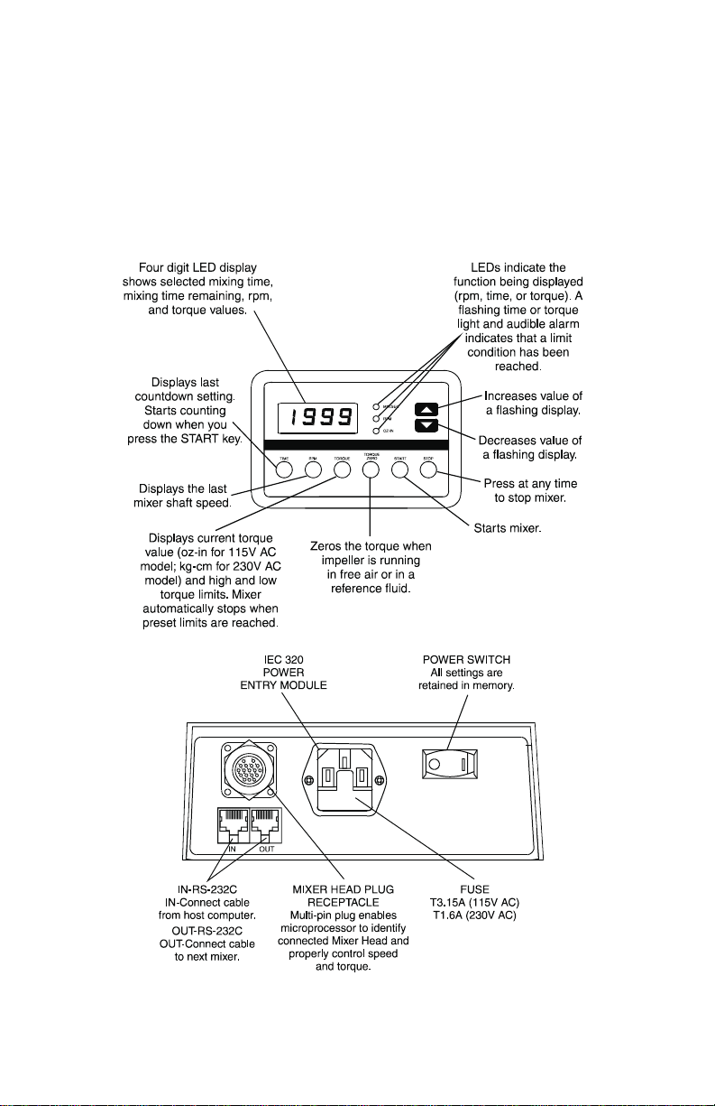
CONTROL/DISPLAY FUNCTIONS
Figure 1. Controller Rear Panel
2
Page 5
INSTALLATION AND SETUP PROCEDURE
The Mixer Heads are equipped with an adjustable-tilt Mounting Assembly.The
Mounting Assembly is designed to be attached to an optional mixer Support
Stand, or Tank Clamp. Components supplied as part of the mixer package
include the following:
Mixer Head with 6-ft cable
·
Precision Controller with 6-ft line cord
·
JACOBS
·
0.375 inch collet on high speed mixers
·
Adjustable-tilt Mounting Assembly with Support Rod
·
®
-type chuck on high torque mixers
Installation of Adjustable Tilt Mounting
W ARNING: Neverinsert orremovethe mixer shaft/impeller
while the mixer shaft is rotating.
Perform the following steps.
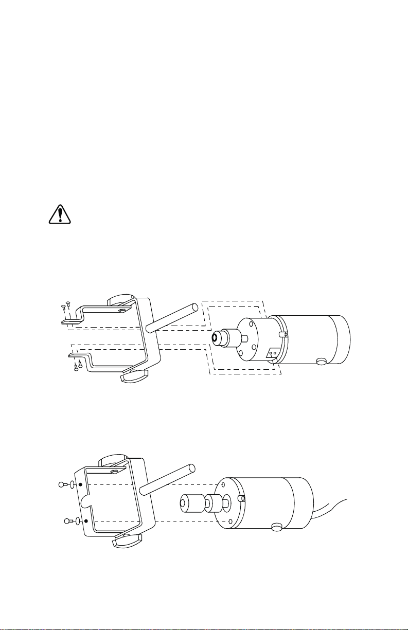
1. Attach Mixer Head to adjustable-tilt Mounting Assembly as follows:
a. For models 50003-10, 50003-15, 50003-20, and 50003-25 attach
Mounting Assembly with four screws and lockwashers.(See Figure 2.)
Figure 2. 50003-10, 50003-15, 50003-20, and 50003-25
Mixer Head Mounting
b. For models 50003-30, 50003-35, 50003-40, and 50003-45 attach
MountingAssemblywith twoscrewsandlockwashers.(SeeFigure3.)
Figure 3. 50003-30, 50003-35, 50003-40, and 50003-45
Mixer Head Mounting
3
Page 6

Note: The mixeris now ready to be attached toa SupportStand or to aTank
Clamp (not supplied). Recommended stands, T ank Clamps, and a
double (rod) clamp are available through your dealer. Part numbers
are listed in the ACCESSORIES section.
Installation Using a Support Stand
1. SetupSupportStandin accordancewith themanufacturer’sinstructions.
2. Attach a double (rod) clamp to the vertical rod on the Support Stand and
tighten clamp screw. (See Figure 4.)
3. Slide rod of adjustable-tilt Mounting Assembly into clamp and secure with
clamp screw.
4. Select an impeller and shaft for the required operation and install as
follows:
a. Place impeller on shaft and tighten set screw.
b. Forhigh-torque MixersHeads,slidetheshaft of the stirring device into
the JACOBS
c. For high-speed Mixer Heads, slide the shaft through the collet and
hand tighten collet.
5. Place SupportStand legs around vessel.Tilt angle is adjustablefrom 0 to
30 degrees.
®
-chuck and tighten chuck with key supplied.
W ARNINGS: Exercise extreme care when adjusting Mixer
Head height and/or position to avoid personal
injury.Nevermakethese adjustmentswhilethe
mixer shaft is rotating.
Mixer shafts must be inserted into high speed
through-shaftmixers at least 3 in and the collet
hand-tightened firmly to insure adequate shaft
retention. Keep mixer shafts as shor t as
possible to reduce resonant vibrations caused
by shaft flexing at higher speeds.
6. Position the height of the Mixer Head by moving the clamp up or down on
the Support Stand or on high-speed models by loosening the collet and
positioning the shaft.
4
Page 7
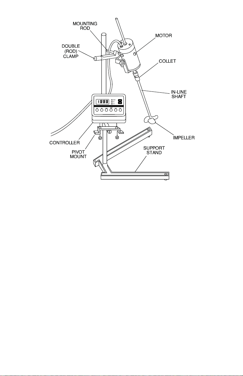
Figure 4. Typical Mixer Setup Using a Support Stand
Note: The Controller can be placed on any flat surface within 6 feet of the
MixerHead orcanbe mounted on a Support Platform (not supplied)or
a Pivot Mount (not supplied).Refer to the ACCESSORIES section for
part numbers.T oattach the Support Platform proceed with step 7.T o
attach the Pivot Mount proceed with step 8. If Controller is placed
elsewhere proceed with step 9.
7. To install the Support Platform proceed as follows:
a. Attachadouble (rod)clamp totheverticalSupportRodand positionso
that platform will be clear of Mixer Head.
b. Slide the mounting rod of the Support Platform into the double (rod)
clamp and tighten clamp.
c. Place Controller on platform and proceed to step 9.
8. To install the Pivot Mount proceed as follows:
a. Remove the two cap nuts from the mounting studs on bottom of
Controller.
5
Page 8

b. P ositionPivotMountbracketovertwostuds, re-installtwo capnuts and
tighten.
c. Attach a double (rod) clamp to the vertical Support Rod on the stand
and position so that Pivot Mount bracket will be clear of Mixer Head.
d. Slidethe mounting rod ofthe PivotMount bracketintothedouble(rod)
clamp and tighten clamp.
e. Adjust position of Controller by first loosening knob on Pivot Mount
bracket, adjust position and then retighten knob.
W ARNING: Check that all cords are clear of any moving
parts and not subject to splashes or spills.
9. Connect the 6-foot cable between the Mixer Head and the Controller rear
panel.
10. Check that the rear panel ON-OFF switch is in the OFF position.
11. Connect the 6-ft. line cord from the Controller to the appropriate 3-wire
grounded power source.
The mixer is now ready to operate.
Installation Using a T ank Clamp
The TankClamp is attached to the side of a tank and supports both the Mixer
Head and the Controller.(See Figure 5.)
1. Position the Tank Clamp over the edge of the tank with large knob to the
outside of tank.
2. Allow clamp to rest on edge of tank for added stability and tighten knob.
3. Position Mixer Head over material to be mixed and insert mixer mounting
shaft into upper hole in Tank Clamp. Tighten locking knob securely.
4. Select an impeller and shaft for the required operation and install as
follows:
a. Place impeller on shaft and tighten set screw.
b. Forhigh-torqueMixer Heads,slide the 5/16inchto 3/8 inch shaftofthe
stirring device into the JACOBS-chuck and tighten chuck.
c. For high-speed Mixer Heads, slide the 0.375 inch mixer shaft through
the collet and tighten collet. Be sure only 0.375 (±0.0005) inch shafts
are used. See your dealer for obtaining the proper shaft size.Refer to
the ACCESSORIES section for the part numbers.
6
Page 9
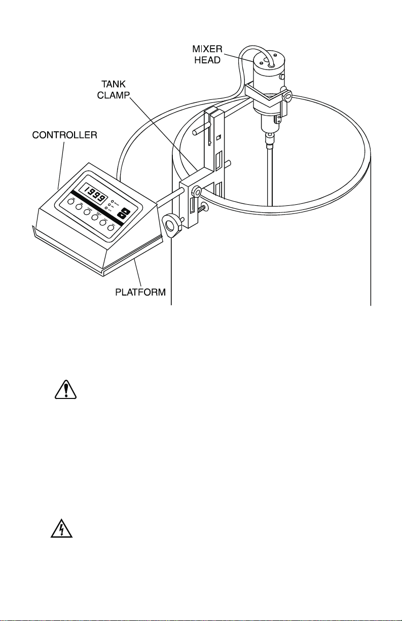
Figure 5. Typical Mixer Setup Using a Tank Clamp
W ARNINGS: Exercise extreme care when adjusting Mixer
Head height and/or position to avoid personal
injury.Nevermake these adjustmentswhile the
mixer shaft is rotating.
Mixer shafts must be inserted into high speed
through-shaft mixers at least 3 inches and the
collethand-tightened firmlyto insure adequate
shaft retention. Keep mixer shafts as short as
possible to reduce resonant vibrations caused
by the shaft flexing at higher speeds.
DANGER: Do not operate mixers where explosive vapors
or flammable materials exist. Death or serious
injury couldresult.Check NECand local codes
before installing.
7
Page 10

5. Position the height of the Mixer Head on high-speed models by loosening
the collet and positioning the shaft.
Note: The Controller can be placed on any flat surface within 6 feet of the
MixerHead and can be mounted on a SupportPlatform (not supplied)
or a Pivot Mount (not supplied). Refer to ACCESSORIES for part
numbers.ToattachtheSupportPlatformproceedwith step 6.Toattach
the Pivot Mount proceed with step 7.If Controller is placed elsewhere
proceed with step 8.
6. To install the Support Platform proceed as follows:
a. Slide the mounting rod of the Support Platform into the lower hole on
the Tank Clamp and tighten clamp.
b. Place Controller on platform and proceed to step 8.
7. To install the Pivot Mount proceed as follows:
a. Remove the two cap nuts from the mounting studs on bottom of
Controller.
b. P ositionPivotMount bracketovertwo studs,re-installtwo cap nutsand
tighten.
c. Slide themountingrod of thePivotMount bracketinto thelowerholeon
the Tank Clamp and tighten clamp.
d. Adjust position of Controller by first loosening knob on Pivot Mount
bracket, adjusting position and then retighten knob.
8. Connect the 6-foot cable between the Mixer Head and the Controller rear
panel.
9. Check that the rear panel ON-OFF switch is in the OFF position.
10. Connect the 6-ft. line cord from the Controller to the appropriate power
source,either a 90-130V AC 50 or 60 Hz 3-wire grounded power source or
a 200-260V AC 50 or 60 Hz 3-wire grounded power source.
W ARNING: Check that all cords are clear of any moving
parts and not subject to splashes or spills.
The mixer is now ready to operate.
8
Page 11

OPERATION
W ARNINGS: Always wear appropriate eye protection when
mixing any kind of fluid.
Avoid wearing loose clothing that may be
caught by a rotating mixer shaft.
Use care when setting the operating speed of
the mixer. Operation at high speeds in small
mixing vessels could result in hazardous
splashing on the operator and equipment.
Power On
AnEEPROMpermitsstorage of all previously set parameters including speed,
torque,time andcalibration constant.Turning the rear panel mountedON/OFF
switchtothe“ON”positionenergizes thedisplaywithoutrunningthemotor.The
display will come up in the last mode operated.Depressing the START button
causes the mixer motor shaft to rotate at the previously programmed speed.
Depressingthe STOPbuttonstops the motor.ChangingDisplayModes(TIME,
RPM, TORQUE) is accomplished by pressing the desired mode button once.
Additional operation of the mode button advances operation to the set mode.
Set Run Time
The use of the TIME button in conjunction with the INC/DEC buttons permits
entry of a desired mixing time.Pressing the TIME buttononce when already in
the Time Display Mode causes the left (minutes) digit to flash, pressing the
TIME button once again causes the right two (seconds) digits to flash. During
this period the time can be set with the INC/DEC buttons. Pressing the TIME
button a third time starts the countdown provided the motor is running;
otherwise the display shows the set time. Maximum programmable time is 99
minutes 59 seconds. A “0” programmed time results in continuous motor
operation.
Set Motor Speed
Depressingthe RPM button when in theRPMmodecausesthe display to flash
and read set motor speed. Use of the INC/DEC buttons changes the desired
speed.
Set Motor Torque Limit
W ARNINGS: Neverinsertor removethemixer shaft/impeller
while the mixer shaft is rotating.
When running at full speed and load at higher
ambient temperatures,the Mixer Head may get
very hot to the touch.
9
Page 12

The TORQUE limit feature provides for the setting of both HI and LO torque
limits.Depressingthe TORQUEbuttonwhen in theTORQUEmodecauses the
first digit of thedisplayto read either on “H”or “L”(for High or Low limit) and the
last three digits to flash and read the set limit. Pressing the INC/DEC buttons
changes the set torque limit.
Pressing the T orquebutton once again while the digits areflashing causes the
H or L to flash while the set limit digits stop flashing. It is now that the High or
Lowlimitcan beselectedbypressing eithertheINC/DECbuttons.Pressingany
button other than INC/DEC buttons returns the display to actual torque. If the
motor is running while the torque limit is being modified the previously
programmed limit will be in effect until the torque limit mode is exited;then the
new limit will take over.
Regardlessof theset torquelimit,there isalwaysa maximumtorque limitcheck
toguard against motoroverheating.Ifthislimitis exceededthe motor stops,the
alarm sounds, the display flashes “HI” and the oz-in/kg-cm LED flashes.
Pressinganykeycausesthedisplayto return to what was previouslydisplayed
before the alarm. The error must be corrected or the over-limit warning will
sound again when the motor is restarted.
TheTORQUEZERO buttonis used to zerothe torque displayso that theactual
torque necessaryto mix something can be read directly on the display.T ouse
thisfeaturethe TORQUEZERO buttonispressedwhile the mixer head shaft is
running in free air; the display will zero .The mixer shaft is then placed into the
solution being mixed, the reading on the display will now indicate the torque
necessary to mix the solution. This number can now be used in helping
determinethepropershut off or torquelimitwhen mixing severalbatches tothe
same consistency.
When the TORQUE ZERO button is operated, the maximum torque limit that
can be set is adjusted so that the absolute torque does not exceed the
continuous torque of the mixer head being used.
Example:The operator has set a high torque limit of 50 oz-in for a motor rated
for 65. The motor is then running with an actual torque reading of 30 oz-in.
Whenthe TORQUEZERO button is pressed, the maximum torque that canbe
set would be 35 (65-30). Since the set limit of 50 is above this, it will
automaticallybe changed to35.Theoperator willseethis when thesetmode is
entered, which will prev ent a setting over 35.
An audible alarmwill sound and the LED that corresponds to the limit that has
been reached will flash when either the preset time or the torque limit is
reached. Both the LED and alarm will cycle on and off until turned off by
pressing any button other than the INC/DEC buttons.
Remote Operation Via Serial Port
Refer to APPENDIX A for computer controlled remote operation.
10
Page 13

MAINTENANCE AND TROUBLESHOOTING
Maintenance is limited to replacement of motor brushes on the Mixer Head,
replacingthefuse on the Controller,and cleaning theunits.If a faultis detected
when troubleshooting and cannot be corrected by the suggested remedy ,
contact your dealer for service.
Motor Brush Check/Replacement
Note: Brushes should be checked every 6 months or 1000 operating hours
or if erratic operation occurs.Erratic operationmayoccur immediately
after brush replacement. Allow motor to run up to an hour to allow
brushes to seat.
1. Place the rear panel ON-OFF switch in the OFF position.
2. Disconnect the AC line cord from the AC receptacle.
3. Disconnect the Mixer Head cable from the receptacle on the rear of the
Controller.
4. Carefully unscrew each brush holder cap. Withdraw the brush, and
examine it for wear.
Note: Replace both brushes if either brush is less than 0.300 inch (8 mm)
long. The replacement brushes (set of 2) part number is listed under
REPLACEMENT P ARTS.
5. Insert brushes into brushholder on each side of motor as shownin Figure
6 and screw in brush holder caps.
6. Reconnect Mixer Head to rear panel connector on Controller.
7. Reconnect Controller to primary power source.
Figure 6. Motor Brush Orientation
11
Page 14

Controller Fuse Replacement
1. Place the power switch in the OFF position.
2. Disconnect the AC power input line cord from the AC receptacle.
3. Remove and check the fuse and replace if defective.
4. Reconnect the AC power input line cord to the AC receptacle.
Cleaning
W ARNING: Never clean the Controller or Mixer Head while
power is applied to the system.
Keep the Mixer housing and Controller enclosure clean with mild detergents.
Never immerse nor use excessive fluid.
Replacement Parts
No user-serviceable partsare
dealer.
The following parts
Description Part Number
Fuse, T3.15A (model 50003-00) 77500-25
Fuse, T1.6A (model 50003-05) 77500-11
Motor Brushes (2) 07520-04
Brush Cap (1) A-2542-CR
JACOBS-ChuckAssembly (50003-10, 50003-15,
50003-20, and 50003-25) B-3094
Chuck Key (50003-10, 50003-15,
50003-20, and 50003-25) B-2809-2
Collet Nut (50003-30, 50003-35,
50003-40, and 50003-45) A-3535-0012
Pivot Assembly Knob (1) B-1083-39
Cordset–USA (115V units) 50001-68
Cordset–European (230V units) 50001-70
Cordset–British (230V units) 50001-72
Cordset–Swiss (230V units) 50001-74
Cordset–Italian (230V Units) 50001-76
Cordset–NEMA (230V units) 50001-78
Contact your dealer if you have service needs.
are
inside
of this instrument.Referservicingto your
user-replaceable:
12
Page 15

Troubleshooting
TheController microprocessordetectsand indicates systemfaults.Thedisplay
alternately shows the error number and a “Fail”message. The following table
summarizes the faults and suggested correctiveaction.The system cannot be
operated until the fault is corrected.
Error Code Fault Corrective Action
Err1 No Mixer Head
Connection
Err2 Invalid Mixer Head Bad motor cable—return Mixer
Err3 No encoder pulses Return Mixer Head and
Err4 Motor speed is
excessive
Err5 No torque information
display
Err6 Bad PROM check Return Controller for repair.
Err7 Motor overload Check mixer for obstructions.
Err8 Zero cross failure Return Controller for repair.
Err9 Bad EEPROM data or
WRITE/VERIFY error.
Plug Mixer Head into Controller.
Head for repair.
Controller for repair.
Return Mixer Head and
Controller for repair.
Return Controller for repair.
Unit must be turned off to clear
error.
Return Controller for repair.
“HI”Limit Message
Aflashing “HI”limitmessage willbe displayedandtheMixerHead willstopif the
maximumrated torque oftheMixerHead is exceededwhen the lowtorquelimit
mode is being used. To protect the Mixer Head motor from overheating, it
cannot be restarted until the fault is corrected.
Note: Before contacting your dealer for repair, try to determine whether the
fault is in the Controller or Mixer Head.The best way is to substitute a
known good unit, if available and recheck.
13
Page 16

ACCESSORIES
The accessories listed below, used for mounting the Mixer Head and
Controller, are available from your dealer. Many other accessories such as
shafts and impellers are also available.Contact your dealer for the full line of
available accessories.
Part Name Part Number
Tank Clamp 50001-80
Controller Support Platform 50001-90
Pivot Mount Controller Support 50001-82
Support Stand 50001-92
Double (Rod) Clamp 08047-20
Software 07550-72
Servodynes RS-232-C Interface Cable 07550-64
Satellite Cable 07550-66
Shaft, 12 inch 4553-52
Shaft, 18 inch 4553-57
Shaft, 24 inch 4537-10
Shaft, 30 inch 4538-10
SPECIFICATIONS
Mixer Head
Output:
Direction of Rotation: CCW (Impeller end)
Speed Range:
Models 50003-10 and 50003-15 3–180 rpm
Models 50003-20 and 50003-25 20–900 rpm
Models 50003-30 and 50003-35 60–2300 rpm
Models 50003-40 and 50003-45 150–6000 rpm
Torque Output, max.:
CONTINUOUS INTERMITTENT
Models 50003-10 and 50003-15 340 oz-in 510 oz-in
Models 50003-20 and 50003-25 70 oz-in 105 oz-in
Models 50003-30 and 50003-35 45 oz-in 65 oz-in
Models 50003-40 and 50003-45 17 oz-in 25 oz-in
14
Page 17

Specifications (Continued)
Mixer Shaft Interface:
Models 50003-10 and 50003-15 JACOBS-typechuckwith key accepts
Models 50003-20 and 50003-25 5/16 in to 3/8 in dia shaft
Models 50003-30 and 50003-35 Collet accepts 0.375 (±0.0005)
Models 50003-40 and 50003-45 in dia shaft
Input:
Voltage, max.:
50003-10, -20, -30, -40 90V DC
50003-15, -25, -35, -45 180V DC
Current, max.:
50003-30 and -40 2.3A
50003-35 and -45 1.2A
50003-10 and -20 1.5A
50003-15 and -25 0.8A
Installation Category: Installation Category I per IEC 664
(Signal lev el–parts of equipment)
Construction:
Dimensions (L x Dia): 11.5 in x 3.6 in (292 x 92 mm)
Weight: 8 lb (3.5 kg)
Enclosure Rating: IP 24 per IEC 34-5
Environment:
Temperature, Operating: 0° to 40°C (32° to 104°F)
Temperature, Storage: -45° to 65°C(-49° to 149°F)
Humidity (non-condensing): 10% to 90%
Altitude: Less than 2000 m
Pollution Degree: Pollution Degree 2 per IEC 664
(Indoor Usage–lab,office)
Chemical Resistance: Exposed material is painted
aluminum, plastic and vinyl
Compliance:
115V: UL508, CSA C22.2, No.14-M91
230V: EN61010-2-051: 1995
(EU Low Voltage Directive)
15
Page 18

SPECIFICATIONS
Controller
Output:
Voltage, max.:
50003-00 90V DC
50003-05 180V DC
Current, max.:
50003-00 2.3A
50003-05 1.2A
Speed regulation:
Line: ±0.25% F.S.
Load: ±0.25% F.S.
Drift: ±0.25% F.S.
Display: Four-digit, seven segment LED
Maximum settable
Countdown Time: 99 minutes, 59 seconds
Time Accuracy: ±1 second
Input:
Voltage, max.:
50003-00 90 to 130 Vrms @ 50/60 Hz
50003-05 200 to 260 Vrms @ 50 Hz
Current, max.:
50003-00 2.3A
50003-05 1.2A
Installation Category: Installation Category II per IEC 664
(Local lev el- appliances, portable
equipment, etc.)
Computer Control: RS-232-C (Full Duplex)
Construction:
Dimensions: (LxWxH) 7.8inx6.5inx3.5in
(197 x 165 x 89 mm)
Weight: 3 lb (1.4 kg)
Enclosure Rating: IP 22 per IEC 529
Environment:
Temperature, Operating: 0° to 40°C (32° to 104°F)
Temperature, Storage: -45° to 65°C(-49° to 149°F)
Humidity: (non-condensing) 10% to 90%
Altitude: Less than 2000 m
16
Page 19

Specifications (Continued)
Pollution Degree: Pollution Degree 2 per IEC 664
(Indoor Usage–lab,office)
Chemical Resistance: Exposed material is painted
aluminum, plastic and vinyl
Compliance:
115V: UL508, CSA C22.2, No.14-M91
230V: EN61010-2-051: 1995
(EU Low Voltage Directive)
17
Page 20

W ARRANTY
The Manufacturer warrants this product to be free from significant deviations
from published specifications. If repair or adjustment is necessary within the
warranty period, the problem will be corrected at no charge if it is not due to
misuseorabuseon your partas determinedbytheManufacturer.Repair costs
outside the warranty period, or those resulting from product misuse or abuse,
may be invoiced to you.
The warranty period for this product is noted on the Warranty Card.
PRODUCT RETURN
Tolimit charges and delays,contact the sellerorManufacturerforauthorization
and shipping instructions beforereturning the product, either within or outside
ofthe warrantyperiod.When returningthe product, please state the reasonfor
the return. For your protection, pack the product carefully and insure it against
possibledamage or loss.Any damages resulting fromimproper packagingare
your responsibility.
TECHNICAL ASSIST ANCE
If you have any questions about the use of this product, contact the
Manufacturer or authorized seller.
18
Page 21

APPENDIX A MIXER COMMUNICATION SPECIFICATION
1.0 – Linkable Instrument Network
The Linkable Instrument Network is a serialcommunication system consisting
of a control computer with one RS-232-C port and one or more mixer
controllers. This description descr ibes all the information needed to
communicate with a mixer controller.
All communications between the control computer and the mixer controller
units is based on a pseudo daisy-chain principle.The transmission line of the
computer will pass through the input and output buffers in each of the satellite
units. Each satellite unit has the ability to turn the buffers on and off to block
communications from other units below it in the daisy-chain. For
communications to work properly,AC power must be applied to all mixer units
connected to the daisy-chain.
The receive line of the control computer originates in the transmitter of the last
satellite in the chain. It is double buffered through each satellite so that each
output will only see one load.
Athirdline,theRequestT oSend(RTS)isasimilarly bufferedline.Eachsatellite
has the ability to activate this line to signal the computer its request to send.
The maximum number of satellites is limited to 25 by the Linkable Instrument
Networksoftware tominimizecommunicationtime.Howe ver,up to89satellites
could be controlled by a single RS-232-C port using custom software since
satellites can be assigned any number from 01 to 89.
1.1 – Serial Connections
The satellite units have two 4-wire, 6 position modular phone jacks labeled
“RS-232 IN” and “RS-232 OUT”. The control computer will have a standard
DB-25 plug as found on most RS-232-C connections. The DB-9 “AT” style
connector can also be used with a custom cable or DB-9 to DB-25 adapter
cable.
“RS-232 IN” JACK
Pin 1 — Receive signal from the computer
Pin 2 — Transmit signal to the computer
Pin 3 — Ground
Pin 4 — Request to send (RTS) to the computer
“RS-232 OUT”JACK
Pin 1 — Request to send (RTS) from the next mixer
Pin 2 — Ground
Pin 3 — Receive signal from the next mixer
Pin 4 — Transmit signal to the next mixer
19
Page 22

DB-25 PLUG ON CONTROL COMPUTER
Pin 2 — Transmitted data to mixer
Pin 3 — Received data from mixer
Pin 5 — Clear to send — RTS from mixer
Pin 7 — Ground
DB-9 PLUG “AT type” ON CONTROL COMPUTER
Pin 3 — Transmitted data to mixer
Pin 2 — Received data from mixer
Pin 8 — Clear to send — RTS from mixer
Pin 5 — Ground
Figure A-1. Serial Daisy-Chain Connections
Theseriallineand connectors are standard telephone4wire cables andRJ-11
connectors. In-line adapters are available to connect two cables together to
facilitate the interconnection of two cables if a mixer is removed.
1.2 – Serial Data Format
The serial data format is full duplex (simultaneously transmit and receive), 1
start bit, 7 data bits,oneodd paritybit,andonestop bit at 4800 bits per second.
All data transmitted consists of characters from the standard ASCII character
set.Note: Odd parity is defined such that the sum of the eight individual bits is
an odd number (1,3,5 or 7).
20
Page 23

1.3 – Serial Protocol
Alltransmissions originateorare requested bythe controlcomputer(master).It
may issue commands directly and it may request that the mixer report.When
asked to report, the mixer sends the data requested. Should a mixer require
communication with the computer, it has the ability to activate its request to
send (RTS) line. Upon detecting the RTS, the control computer would initiate
communications to determine why the RTS line is active (see section 1.11).
1.4 – Start Up Sequence
Normal start up consists of turning on all the mixer units first and then the
control computer.Each mixer unit enables its RS-232-C buffers and activates
itsRTSline.The control computer then sendstheenquire<ENQ>commandin
response to the active RTS line. Upon receiving the <ENQ> command, all
mixers with an active RTS line disable their receive and transmit buffers to the
mixersbelowthem inthe daisy-chain.Nextthemixerunit(s)wouldrespondwith
<STX>MMx<CR> indicating that it is a satellite mixer and it needs to be
numbered.The“x”isa characterfrom 0to9 orAto Findicatingthe typeofmixer
currentlyconnected.Thecontrol computeronlysees theresponse fromthe first
mixer in the chain since communications with the others is now blocked. The
control computer then sends back <STX>Mnn<CR> with nn being the desired
mixernumberstartingwith01forthefirst mixerandincrementingforeach mixer
up to 25 maximum.If the mixer unit receives the data withouterrors it performs
the following steps:
1. Deactivates its RTS line.
2. Sends an <ACK> to the control computer.
3. Enables the transmit and receives buffers for the next mixer.
4. Changes its display from “00” to number it received.
After the control computer receives the <ACK> it sees the RTS from the next
mixerand again issues the <ENQ> command.The above process is repeated
until all mixers are numbered.
If a mixer does not receive valid data from the control computer or detects a
transmission error (parity, framing, overrun), it sends a <NAK>. When the
controlcomputerreceives the <NAK> it resends the numberassignmentstring
tothe mixer.Section1.10onerrorhandling describes the maximum re-tries the
control computer performs.
If a mixer is turned on after all the other mixers have been numbered, it will be
numbered the same as described above with the next available number if no
commandshavebeen senttothe othermixers.If commands havebeenissued,
the mixer is assigned a temporary number starting with 89 and decrementing
for each subsequent mixer. This will cause the mixer to release its RTS so
normal communication can proceed. The operator will be alerted to the
conditionthat another mixer has come on-line and needs tobenumbered.The
operator will then be able to assign the new mixers a number so that they will
appear correctly in the system.
21
Page 24

If a mixer is requesting to be numbered and the control computer has already
issued25 mixernumbers,it willassignthe mixerthenumber89 as described in
the preceding paragraph and alert the operator to the situation.
If a mixer is powered down after it has been numbered, it will be treated as a
new unit as described above when it is powered up again.
1.5 – Remote / Local Operation
Once a mixer unit is assigned a number,it will keep the numberuntil thepower
switchis turnedoff.Itcanbereturned to local mode using the control computer
andthe“L”command.If the control computer program is no longer running, the
mixer can be powered off and then on to return it to local operation. If the “L”
command is used, the mixer will retain its assigned number and respond to
request commands from the control computer but ignore control commands.
1.6 – Command Format
Most commands from the control computer are preceded with the start of text
<STX> character (02 hex), a mixer identification letter (M for Mixer) and a two
digit mixer number (01 through 89). Numbers 00 and 90 through 99 are
reserved for special cases. Following the mixer number is the command
character and then the parameter field which varies in size from zero
charactersto20depending onthe command.Acarriagereturn<CR>, (0Dhex)
is used to indicate the end of a command string. The exceptions to this
command string format are the enquire, acknowledge, and negative
acknowledge(<ENQ>, <ACK>,and<NAK>).These three commands are sent
as a single character .
Five of the mixer unit commands can have a “99” for the mixer number to
indicate the command is for all mixer units.This allows units to simultaneously
be started, stopped, or for status checking.The specific commands to do this
are described in section (1.8).
<STX> M 01 S - 0130<CR>
Start of T ext (02 hex) Carriage Return (0D hex)
Mixer identification Parameterfield (0-20 char)
Mixer number Command character
22
Page 25

More than one command can be put in a command string as shown below:
<STX>M09S-500Q>20T90G<CR>
The above multiple command string example would set the speed at mixer
satellite 09 to 500 rpm, seta high torque limit of 20 oz-in,set the runtime to90
seconds,andturnthemotor on.Themaximum numberof charactersallowedin
a mixer command string is 24, including <STX>, Mnn and <CR>.
COMMAND CHARACTERS FROM CONTROL
COMPUTER TO MIXER
B Preset alarm output to specified state when G
command is executed 0=off, 1=on
F Request cumulative running time none
G Go(turn mixer on and alarm output if preset) none=timed run
H Halt (turn mixer off) none
I Request status data none
J Set torque zero reference none
K Request front panel switch pressed since last K
command none
L Enable Local operation none
NN Initialize units for status request none
O Controlalarm output 0=off, 1=on
Q Sethigh or low torque limit >xxx.xx or <xxx.xx
Q Requestactual torque none
R Enable Remote operation none
S Set motor direction and speed
NOTE: Units are not reversible
S Request motor direction and speed none
T Set time to go in seconds xxxx
T Request time to go none
U Change mixer number nn=new mixer
Z Zero time to go none
PARAMETER FIELD
0=continuous run
>=high, <=low limit
+xxxx.x, -xxxx.x
+=CW, -=CCW
number
Table 1. Control Computer to Mixer Commands
23
Page 26

CONTROL COMPUTER
COMMAND STRING
<STX>MnnBx<CR> x:0=off, 1=on <ACK>
<STX>MnnF<CR> <STX>Fxxxxxx<CR> xxxxxx =
cumulative run time (999,999
seconds max)
<STX>MnnG<CR> <ACK> or none if M99 or P99
<STX>MnnH<CR> <ACK> or none if M99 or P99
<STX>MnnI<CR> <STX>MnnIxx0xxx<CR>
(see section 1.8.1)
<STX>A99I<CR> <STX>MnnIxx0xxx<CR>
(see section 1.8.1)
<STX>MnnJ<CR> <ACK>
<STX>MnnK<CR> <STX>Kx<CR> (see section 1.12)
<STX>A99NN<CR> (see section 1.8)
<STX>MnnOx<CR> x:0=off, 1=on <ACK>
<STX>MnnQ>xxx.xx<CR> <ACK>
<STX>MnnQ<CR> <STX>Q016.00<CR>
<STX>MnnS-1000<CR> <ACK>
<STX>MnnS<CR> <STX>S-1000.0<CR>
<STX>MnnTxxxx<CR> <ACK>
<STX>MnnT<CR> <STX>T0069<CR>
<STX>MnnUnn<CR> nn=01 to 89 <ACK>
<STX>MnnZ<CR> <ACK>
MIXER RESPONSE
Table 2. Sample Mixer Commands and Responses
1.6.1 – Command Features
1. Initializing
Once a mixerunit has been assigned a number, it must first be sent a SPEED
and a TIME before the GO command can be sent. If the continuous run GO
command is used, onlya SPEED needs to be sent.Failureto do this will result
in a <NAK> from the mixer when it receives the GO command. The set torque
will default to the high limit equal to the maximum continuous torque rating for
the attached mixer head.
2. Setting Speed
The set speed command also includes a direction character,“+”for clockwise,
“-” for counter clockwise. The mixer is NOT reversib le, so the direction
24
Page 27

character must match the direction for the connected Mixer Head. An invalid
direction character in the set speed command will result in a <NAK> from the
mixer unit.
3. Setting Time
Whentimeto go is set with the T command, it isadded tothe currenttime togo
counter.The maximum this counter can be is 9999 seconds. If a time to go is
sent to the mixer which would cause the counter to overflow past 9999, the
mixerwill not add the valueto the counter and will send the control computer a
<NAK>. The time to go counter can be set to zero by using the Z command,
which will also cause the mixer to stop if it is running when the Z command is
received.Whenthetime togo counteriszero,themixercanonly bestarted with
the continuous run GO command.
4. Setting Torque Limit
The torque limit can be set to a high or low limit by preceding the torque limit
numberwitha “>”or“<”character.If thischaracter isomitted, thedefaultlimitwill
behigh.Whentheactual torqueexceedstheset torquelimit,the motorwillstop.
The control computer can determine the cause of the stop by requesting the
time to go (T command).If the time to go is greater than zero, then the torque
limitstoppedthemotor,otherwiseitwasbecause theruntime wascompleted.
1.7 – Control Computer Parameter Fields
The parameter field for each command is variable in length. The control
computer will have the option of using leading zeroes, leading spaces, or no
paddingat all.For example,if asetspeedof 200 rpmwasdesired, the following
list of parameters would all be accepted by the mixer as valid:
ssss-00200.00
(s = space) ssss-200.00
ssss-200.0
ssss-200
ssss-200.00
ssss-200.0
ssss-200
1.7.1 – Mixer Data Fields
Anydata thata mixersends to the controlcomputer willhavea fixed number of
characters which is determined by the command. For example, if the control
computer requested cumulative run time from the mixer, it would always
receive 6 characters representing the cumulative time (000000 to 999999).
1.8 – All Units Commands
Fiveof the mixerunit commands can be used with the special unit number 99,
which indicates the command is for all units. Each of these commands have
special conditions which apply to them as described below.The mixerunit will
ignore all other commands that are used with the 99 unit number.
(1) — <STX>M99G<CR> or <STX>P99G<CR>
25
Page 28

Eitherof thesecommandswill start all mixerunitsthathavebeen initializedwith
a speed and time.This command is not acknowledged by the mixer.
(2) — <STX> M99H<CR> or <STX>P99H<CR>
Either of these commands will stop all mixer units that are currently running.
This command is not acknowledged by the mixer.
(3) — <STX>M99Z<CR>
Thiscommand will zero the time togocounterinall mixer units.Ifamixer motor
isrunning whenthiscommand isreceived,themotor willstop.Thiscommandis
not acknowledged by the mixer.
(4) — <STX>A99NN<CR>
This command is the first part of atwostep command sequence.It instructsall
mixer units to disable their RS-232-C buffers and wait for the A99I command.
While waiting for the next step, the mixer unit will still respond to all other
commands, but only the first mixer unit in the daisy-chain will receive the
commands.The A99I command MUST be sent after the A99NN command to
restore normal communications.These two commands are used to determine
all the mixer units that are on-line. This is much more efficient than having to
send a command to all possible unit numbers and then checking which units
reply.
(5) — <STX>A99I<CR>
This command is the second partof a two-step sequence which is initiated by
the command previouslydescribed.If the mixer unit did not previously receive
theA99NN command, the A99I command will beignored. Otherwise the mixer
willrespond with the status informationasdescribedinsection1.8.1.When the
controlcomputer receivesthestatus information, it will send <ACK>Mnn<CR>
to the mixer with nn being the mixer unit number that replied.When the mixer
unit receives the <ACK> it will enable its RS-232-C buffers. The control
computerwouldthen repeat this sequence until no more units reply to the A99I
command, indicating all units have enabled their RS-232-C buffers.
26
Page 29

1.8.1 – Mixer Status Request
When the control computer requests status from the mixer (I command or
<ENQ>), the mixer will respond with the following status information:
<STX>MnnIxx0xxx<CR>
Operating status Mixer Head number (0-9, A-F)
(1=remote, 0=local)
Communications status
Alarm status 0=No error, 1=Parity error
(0=off, 1=on) 2=Framing error,
3=Overrun error
Not used in mixer, 4=Invalid command
always zero 5=Invalid data
6=Missing data
Unit status
1=Unit numbered,
waiting for instruction
2=Unit instructed, waiting to go
3=Unit running
4=Unit stopped by local stop
switch
5=No motor feedback
6=Incorrect motor feedback
7=Excessive motor feedback
8=Incorrect motor response—
no torque feedback
9=Max motor torque limit
exceeded
When the mixersends the status information, the communications status byte
willbe reset to zero whenthemixerreceives<ACK>Mnn<CR>from the control
computer.If the mixer receives the I command again before the <ACK>, it will
respond with the same status information.
1.9 – Mixer Response
When the mixer unit correctly receivesa controlcommand, it will sendback an
<ACK>(06 hex) if it was not an all units command (P99 or M99).If data has to
besent backto the masterinresponse tothecommand, itwillbe sent asshown
in table 2. If the mixer detected an error while receiving a command, it will
respond with a <NAK> and not process the command string.If the command
was for all units (P99 or M99) the mixer unit will not <NAK> but will activate its
RTS line and respond with the I command data when the control computer
sends the <ENQ> in response to the RTS.
27
Page 30

1.10 – Error Handling
Depending on the error code received from the mixer, the control computer
would have to take appropriate action to try to eliminate the error condition.
Communication errors of type 1,2 or 3 indicate a hardware type error: noisy
communicationlines,bad connection,glitches orcircuit failure.Communication
error codes 4, 5 or 6 could be hardware errorsas described aboveor software
errors caused by incorrect commands or data being sent by the control
computer.F orhardwaretype errors the control computer would trysendingthe
same command to see if the problem was only momentary.If an error code is
returnedfourtimesin arowor ifthere is noresponse atall,the controlcomputer
would aborttrying to send the command and notify the operator of the type of
error.
If a mixer does not respond at all, the control computer can assume one of the
following:
1. If allothermixersconnected after themixerin question also don’trespond,
the communication link is broken at that point or the mixer is defective.
2. If all other mixers respond, the un-responding mixer is either turned off,
removed from the loop, or defectiv e.
1.11 – Mixer Request to Send
When a mixer wants to communicate with the control computer, it will activate
its request to send(RTS)line and then waitforthe <ENQ> (enquire) character
(05 hex) from the control computer. The following list shows the possible
conditions that would cause the mixer to activate its RTS line.
1. Motor error
2. STOP key pressed at mixer while motor is on
3. Programmed run time completed
4. Torque limit exceeded
5. Power up
6. Error in all units command (M99 or P99)
Following is the sequence of events for when an RTS line is activated:
1. Mixer enables RTS line.
2. When control computer detects RTS, it will transmit the <ENQ> command
(05hex)after it completes any communicationsitmaybe in the process of
doing.
3. When the mixer that has its RTS line enabled receives the <ENQ> it will
disableits RS-232-C buffersto block the other mixersbelow it in the daisychain from communicating with the control computer.This would give the
mixerclosest to the control computer the highest priority if more than one
mixer enabled its RTS line at the same time.
28
Page 31

4. Next the mixer will send the response from the I command as shown in
section 1.8.1.
5. If the control computer received the mixer response without any errors
(parity, overrun, etc.) itwill send an acknowledge<ACK>Mnn<CR> which
will cause the mixer to release its RTS line and enable its RS-232-C
buffers. This will allow the mixers below it in the daisy-chain to
communicate. If the control computer detected any error during the
transmissionit would send the <ENQ>againwhichwouldcause the mixer
tore-send its response.Thecontrolcomputer will re-try a maximum offour
times before aborting and reporting the error to the operator.
6. If more than one mixer had its RTS line enabled, the control computer
wouldsee only the response from the mixer closest to it in the daisy-chain.
After the closest mixer sent its response and released the RTS line, the
controlcomputer wouldsee the RTSoftheother mixerand againissuethe
<ENQ> command which would allow the next mixer with RTS active to
respond.
7. If a mixerwas responding to an <ENQ> command and another mixerwith
higher priority also started to respond, cutting off the first responding
mixer, the control computer would receive invalid data and get some type
of error (parity or framing). This would cause the control computer to
resend the <ENQ>, but this time only the higher priority mixer would
respond since the communications with the lower mixers is blocked.
1.12 – Front Panel Switches
Thecontrolcomputercanreadthemixers front panel switchesbyissuing the K
command.The mixerwill respond with one characterindicating the last switch
pressed since the last K command was acknowledged. If more than one key
waspressed, only the lastone pressed is indicated.After the controlcomputer
receives the mixer unit switch status, it must send an <ACK>Mnn<CR> to
informthe mixeritcan reset the switch status to no key pressed.Table 3 shows
the character returned by the K command and the corresponding switch for
mixer units.
0 = No key pressed 5 = Torque
1 = Start 6 = T orqueZero
2 = Stop 7 = Up arrow
3 = Time 8 = Down arrow
4 = Speed
Table 3. K command key codes for mixer
29
Page 32

1.13 – ASCII Control Characters Used
FUNCTION
DECIMAL HEX
2 02 <STX> Start of Text (CTRL-B)
6 06 <ACK> Acknowledge (CTRL-F)
5 05 <ENQ> Enquire (CTRL-E)
13 0D <CR> Carriage Return (CTRL-M)(CR)
21 15 <NAK> Negative
24 18 <CAN> Cancel (CTRL-X)
CHARACTER
Acknowledge
CONTROL
KEY
(CTRL-U)
Table 4. ASCII Control Codes Used
30
Printed in U.S.A.
031000
 Loading...