

Page 1
OPERATING MANUAL
High Capacity
Vacuum/Pressure Pump
Vacuum/Pressure Station
Barnant Company
28W092 Commercial Avenue
Barrington, Illinois U.S.A.60010-2392
(847) 381-7050
(847) 381-7053 (Fax)
800-637-3739
www.barnant.com
A-1299-0380
Edition 05
115V AC Models
Pump Only 475-3010
Vacuum/Pressure Station 470-5942
SPECIAL APPLICATIONS
Technical information and advice concerning the use of this product in specific applications may be obtained from our Engineering Department. If volume justifies, modifications can be made to adapt the unit to special customer applications. OEM inquiries are welcome and encouraged.
NOTE: The BARNANT COMPANY reserves the right to make improvements in design, construction, and appearance of our products without
notice.
W ARRANTY
The Manufacturer warrants this product to be free from significant
deviations from published specifications. If repair or adjustment is
necessary within the warranty period, the problem will be corrected at
no charge if it is not due to misuse or abuse on your part as determined
by the Manufacturer. Repair costs outside the warranty period, or those
resulting from product misuse or abuse, may be invoiced to you.
The warranty period for this product is noted on the Warranty Card.
PRODUCT RETURN
To limit charges and delays, contact the seller or Manufacturer for
authorization and shipping instructions before returning the product, either
within or outside of the warranty period.When returning the product, please
state the reason for the return. For your protection, pack the
product carefully and insure it against possible damage or loss. Any damages resulting from improper packaging are your responsibility.
TECHNICAL ASSISTANCE
If you have any questions about the use of this product, contact the
Manufacturer or authorized seller.
Printed in U.S.A.
040599
18
Page 2
17
475-3010
The Pump is a chemically resistant, diaphragm operated, variable flow unit
designed for efficient vacuum, pressure, or gas circulating applications. An
integral fan keeps the pump head cool; the temperature of your service
should remain stable.
470-5942
The Pump is teamed up with a Vacuum/Pressure Control Station to provide
easy, convenient regulation of vacuum or pressure .These adjustments can
be made while the pump is running. The system is portable enough for
benchtop laboratory use, plus many commercial applications where reliability and optimum chemical resistance are required.
FLUOREL - Reg TM Minnesota Mining and Manufacturing Co.
NORPRENE - Reg TM Norton Co.
NORYL,VALOX - Reg TM General Electric Co.
VITON - Reg TM DuPont Dow Elastomers L.L.C.
Trademarks bearing the ® symbol in this publication
are registered in the U.S. and in other countries.
VALVE BODY
BALL
SPRING
O-RING
ADJUSTMENT SCREW
PRESSURE REGULATION VALVE
VACUUM REGULATION VALVE
VALVE BODY
BALL
SPRING
O-RING
ADJUSTMENT SCREW
(3) Storage Procedure
If the system will not be in service for any appreciable length of time,
store it in a clean, dry space. Cover any open ports to prevent entry of
dust.Wipe the pow er cord with a dry cloth and inspect for crac ks in the
insulation. Repair any defects or replace the cord before reusing the
pump.
WARNING: Do not modify the plug. And do not connect the grounding
wire to either of the flat blade terminals. (Grounding wire
is green, sometimes with yellow stripes.)
REPLACEMENT PARTS
Service Kit (7530-09)
Composed of: 1 FLUOREL Diaphragm Assembly
1 Pump Head Assembly
(Consisting of 2 valves and 2 valve retainers installed in a
pump head)
Regulation Valve Components
Item Part No
O-RING . . . . . . . . . . . . . . . . . . . . . . . . . . . . . . . . . . .B-1169-11
BALL . . . . . . . . . . . . . . . . . . . . . . . . . . . . . . . . . . . . . . . .A-3988
SPRING . . . . . . . . . . . . . . . . . . . . . . . . . . . . . . . . . . . . .A-3789
VACUUM REGULATION VALVE ASSEMBLY . . . . . . . . . .B-2067
PRESSURE REGULATION VALVE ASSEMBLY . . . . . . .B-2066
Page 3
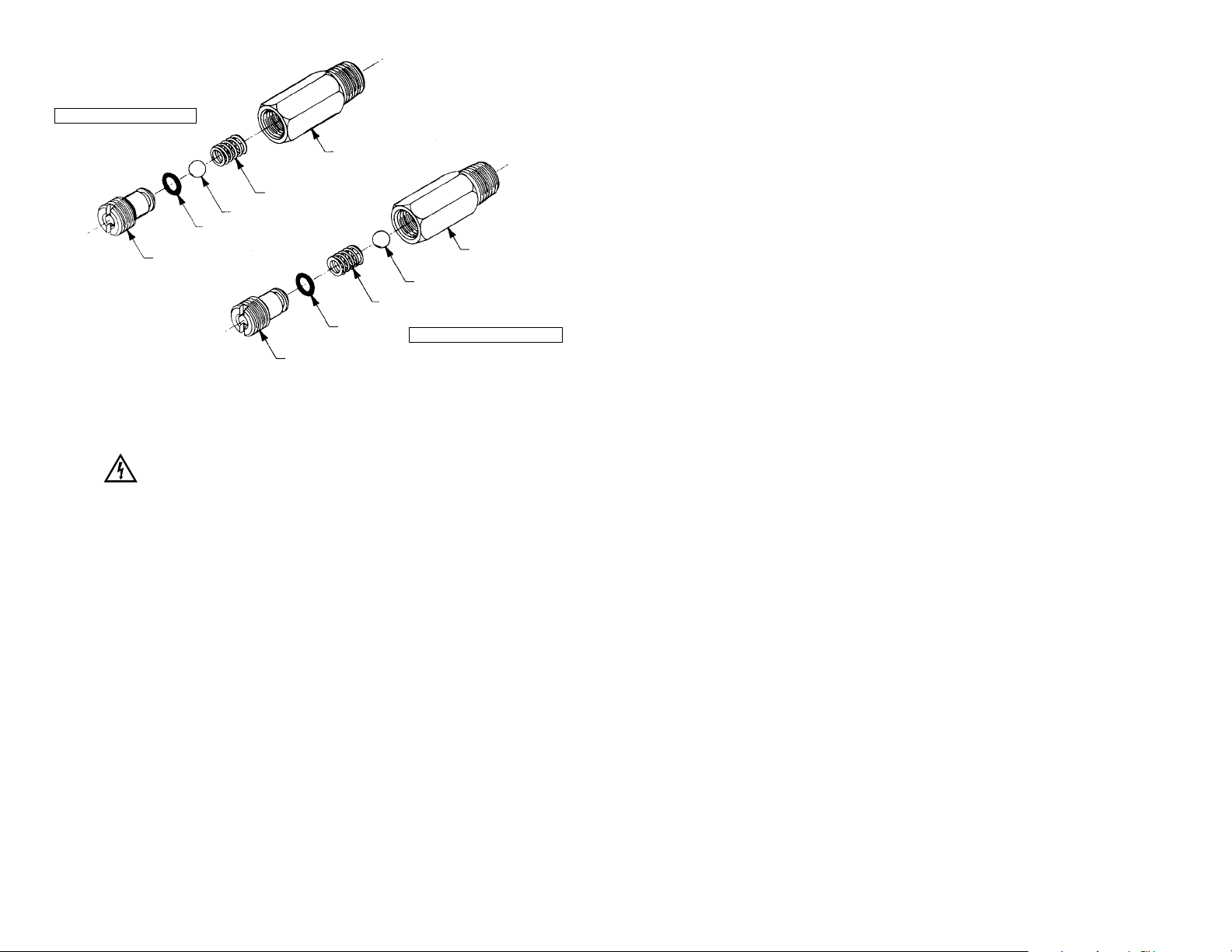
TABLE OF CONTENTS
Title Page
PANEL CONTROLS/CONNECTIONS . . . . . . . . . . . . .See Foldout Page
SAFETY PRECAUTIONS . . . . . . . . . . . . . . . . . . . . . . . . . . . . . . . . . . . 2
INTRODUCTION . . . . . . . . . . . . . . . . . . . . . . . . . . . . . . . . . . . . . . . . . 3
Pressure vs.Vacuum . . . . . . . . . . . . . . . . . . . . . . . . . . . . . . . . . .3
Description . . . . . . . . . . . . . . . . . . . . . . . . . . . . . . . . . . . . . . . . .3
Application Data . . . . . . . . . . . . . . . . . . . . . . . . . . . . . . . . . . . . .5
INSTALLATION PROCEDURES . . . . . . . . . . . . . . . . . . . . . . . . . . . . . . .7
1. Plug in the System . . . . . . . . . . . . . . . . . . . . . . . . . . . . . . . . . .7
2. Connect Tubing . . . . . . . . . . . . . . . . . . . . . . . . . . . . . . . . . . . .7
3. Optional Filter Installation . . . . . . . . . . . . . . . . . . . . . . . . . . . . .7
SETUP PROCEDURES . . . . . . . . . . . . . . . . . . . . . . . . . . . . . . . . . . . . .8
Material Compatibility . . . . . . . . . . . . . . . . . . . . . . . . . . . . . . . . .8
1 Setup for VACUUM Operation . . . . . . . . . . . . . . . . . . . . . . . . . .8
2. Setup for PRESSURE Operation . . . . . . . . . . . . . . . . . . . . . .10
3. Setup for TWO-LINE Operation . . . . . . . . . . . . . . . . . . . . . . .11
SPECIFICATIONS . . . . . . . . . . . . . . . . . . . . . . . . . . . . . . . . . . . . . . . .12
Maximum Vacuum . . . . . . . . . . . . . . . . . . . . . . . . . . . . . . . . . . .12
Maximum Pressure . . . . . . . . . . . . . . . . . . . . . . . . . . . . . . . . . .12
Temperature Range . . . . . . . . . . . . . . . . . . . . . . . . . . . . . . . . . .12
Motor . . . . . . . . . . . . . . . . . . . . . . . . . . . . . . . . . . . . . . . . . . . . .12
FLOW VS. PRESSURE . . . . . . . . . . . . . . . . . . . . . . . . . . . . . . . . . . . .13
Performance Characteristics . . . . . . . . . . . . . . . . . . . . . . . . . . .13
Construction . . . . . . . . . . . . . . . . . . . . . . . . . . . . . . . . . . . . . . .13
MAINTENANCE PROCEDURES . . . . . . . . . . . . . . . . . . . . . . . . . . . . .14
Cleaning . . . . . . . . . . . . . . . . . . . . . . . . . . . . . . . . . . . . . . . . . .14
To Remove the Pump Head . . . . . . . . . . . . . . . . . . . . . . . . . . . .15
To Replace the Diaphragm . . . . . . . . . . . . . . . . . . . . . . . . . . . .15
To Install the Diaphragm . . . . . . . . . . . . . . . . . . . . . . . . . . . . . .15
To Replace the Pump Head . . . . . . . . . . . . . . . . . . . . . . . . . . . .15
1. How to Clean the Regulation Valves . . . . . . . . . . . . . . . . . . .16
2. Motor Overload Protection . . . . . . . . . . . . . . . . . . . . . . . . . . .16
3. Storage Procedure . . . . . . . . . . . . . . . . . . . . . . . . . . . . . . . . .17
REPLACEMENT PARTS . . . . . . . . . . . . . . . . . . . . . . . . . . . . . . . . . . .17
SPECIAL APPLICATIONS . . . . . . . . . . . . . . . . . . . . . . . . . . . . . . . . . .18
WARRANTY . . . . . . . . . . . . . . . . . . . . . . . . . . . . . . . . . . . . . . . . . . . .18
PRODUCT RETURN . . . . . . . . . . . . . . . . . . . . . . . . . . . . . . . . . . . . . .18
TECHNICAL ASSISTANCE . . . . . . . . . . . . . . . . . . . . . . . . . . . . . . . . .18
1
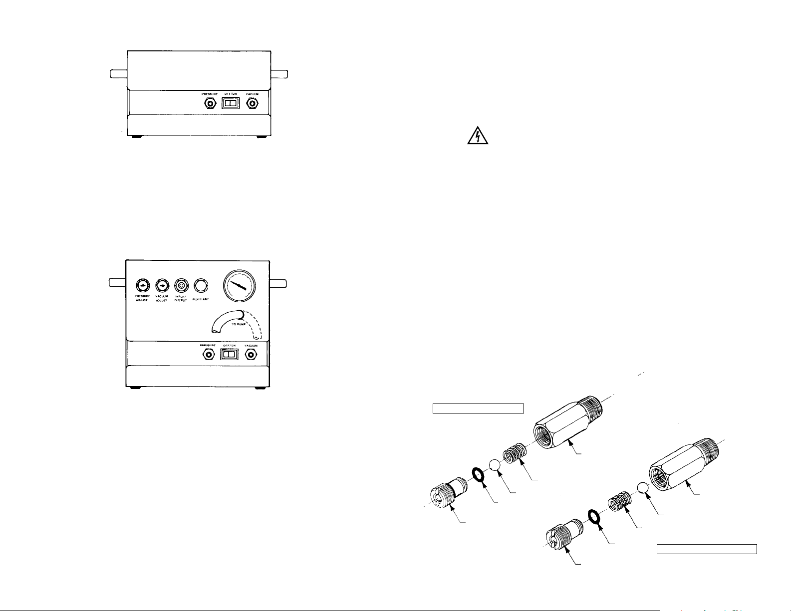
(1) How to Clean Regulation Valves
DANGER: Unplug power cord before any cleaning operation is started.
The PRESSURE ADJUST and VACUUM ADJUST valves should be
occasionally inspected and cleaned.
• Remove the valve elements by turning the adjustment screws CCW.
Use a cotton swab or clean cloth to clean out dirt or grit around the
venting holes.
• Remove BALL and SPRING. Clean the areas around valve seating
surfaces in the VALVE BODY and elements.
• Reassemble VACUUM ADJUST and PRESSURE ADJUST valves.
IMPORTANT: Note that in the VACUUM valve, the SPRING must
go back in first, followed by the BALL. In the PRESSURE valve, the
BALL must go back in before the SPRING.
(2) Motor Overload Protection
The pump motor has an internal thermal overload switch which may
trip if abnormal operation occurs. If the motor stops, check the pump.
If you find no defect, allow the motor to cool for approximately 30 minutes, then restart. If the overload trips again—and no external source
causing the overload can be identified—return the complete unit to
your dealer for repair. (Refer to PRODUCT RETURN section at the
end of the manual.)
16
VALVE BODY
VALVE BODY
BALL
BALL
SPRING
SPRING
O-RING
O-RING
ADJUSTMENT SCREW
ADJUSTMENT SCREW
PRESSURE REGULATION VALVE
VACUUM REGULATION VALVE
Page 4
To Remove the Pump Head
Remove the eight (8) screws holding the pump head to the pump housing.
Do not discard.With the ‘old’head off, examine the diaphr agm f or cr ac ks or
loose particles. Deep cracks would suggest that the diaphragm should be
replaced. Nor mal operation will cause some par ticles to be worn from the
diaphragm. Wipe the diaphragm clean with a dr y cloth or one dampened
with alcohol.If not removed, these particles could affect the perf ormance of
the valves.
To Replace the Diaphragm
Remove the eight (8) screws holding the pump head to the housing. Do
not discard.Slide the diaphragm away from the motor and then lift upward.
Unscrew the bearing collar assembly from the diaphragm. Examine the
bearing; check that the “needles” rotate freely. Install the new diaphragm
onto the bearing collar. Hold the diaphragm center plate, not the rubber
portion of the diaphragm, while the assembly is tightened. Rotate the
eccentric (attached to the motor shaft) by hand while applying grease to the
dowel pin. Use a wooden toothpick or something similar.Don’t scratch the
pin by using a metal object.
To Install the Diaphragm
Rotate the eccentric so that the dowel pin is “upward.” Slide the diaphragm
toward the motor, while gently pushing downward. Align the diaphragm
bead with the groove in the pump housing. It is recommended that a new
pump head be installed whenever a diaphragm is replaced.Excessive wear
particles from the old diaphragm may have entered the valves and
decreased their performance.
To Replace the Pump Head
Position the new pump head so that the flat edge is located toward the
motor.Care should be taken to align the diaphragm bead to the recess in
the pump head before the screws are tightened.Use the original screws to
attach the head onto the housing. IMPORTANT: tighten the screws alter-
nately, at opposite sides of the head, so that it will seat evenly. Use two
steps—first, tighten all to approximately 50 oz-in, then tighten to 100 to 110
oz-in.
CAUTION: Do not disassemble the pump housing from the motor. Proper
assembly (factory adjusted) is critical to proper pump performance.
15
SAFETY PRECAUTIONS
DANGERS: Unplug power cord before any cleaning operation is started.
Improper use of grounding plug can result in a risk of electric
shock.
WARNING: Gas under pressure should not be used for supply as a haz-
ardous bursting condition could develop in the pump head.
Use only gases contained at atmospheric pressure.
CAUTION: Do not operate pump when pressure ports of both heads are
in a blocked condition.
2
WARNING: PRODUCT USE LIMITATION
These products are not designed for, nor intended for use in patient
connected applications; including, but not limited to medical and dental
use and accordingly, have not been submitted for FDA approval.
Page 5

INTRODUCTION
The introductions in this manual are task-oriented.You can go directly to a
particular section and quickly find the answers. The step-by-step installation and setup instructions are easy to follow. Also, functions for all the tubing connections and adjustment valves are defined at the front of the manual for easy reference.
Pressure vs. Vacuum
In relation to atmospheric air, pressure can be positive or negative in a
closed space. In positive pressure applications, the pump compresses
atmospheric air to perform work, usually expressed as pounds per square
inch (psi). In negative pressure applications, the pump reduces the pressure of the atmospheric air to create a vacuum (or suction) to perform work,
usually expressed as inches of mercury (in Hg).
Although the way these pressure differentials are generated and used in a
closed space is exactly opposite, the same equipment can be used by simply changing tubing connections.
Description
The Pump is a chemically resistant, diaphragm operated, variable flow unit
designed for efficient vacuum, pressure, or gas circulating applications. An
integral fan keeps the pump head cool—the temperature of your service
should remain stable.
The Pump is teamed up with a Vacuum/Pressure Station to provide easy,
convenient regulation of vacuum or pressure. These adjustments can be
made while the pump is running.The system is portable enough for benchtop laboratory use, plus many commercial applications where reliability and
optimum chemical resistance are required.
3
MAINTENANCE PROCEDURES
The Vacuum/Pressure Station can be serviced without removal of the
pump.
Service Kit 7530-09 contains a pump head assembly, a diaphragm assembly, and grease. The pump head consists of two valves and two valve
retainers installed in the pump head.The diaphragm assembly consists of
a set screw installed in the diaphragm center plate to a calibrated height.
The grease is needed whenever a diaphragm is replaced.
Cleaning
DANGER: Unplug power cord before any cleaning operation is started.
Keep the pump enclosure clean by using a mild detergent solution.Never
immerse nor use excessive fluid when cleaning the pump.
14
Bearing
Collar
Assy.
Diaphragm
Pump Head
Pump Head
Screws (8)
Valve Retainer
Valve
Valve
Valve Retainer
475-3010
470-5942
Page 6

FLOW vs. PRESSURE
High Capacity
Performance Characteristics
The graph shows typical flow characteristics.
in Hg PSIG
Construction
Rugged, epoxy painted metal housing protects the all-plastic, corrosion
resistant pump. The diaphragm and head cavity provide extended life by
minimizing stress, wear and heat buildup—while optimizing pressure and
vacuum characteristics.
Permanent split-capacitor motor is fan cooled, thermally protected, and has
sealed ball bearings.
Regulation valves are 303 stainless steel.The gauge is bronze and brass.
13
The Vacuum/Pressure Station per mits independent regulation of vacuum
and pressure using an easy reading, dual function gauge. It eliminates the
need for separate systems and elaborate plumbing networks.The horizontal position of regulation valves protects against dirt or dust. Also, pump
vibrations won’t alter your valve settings.
To change from pressure to vacuum, or vice versa, simply switch the VACUUM/PRESSURE TUBING from one port to the other. An auxiliary
input/output port is also provided on the Vacuum/Pressure Station to draw
a vacuum or pressurize a system on tw
o lines simultaneously.
Contamination-free operation is provided via these corrosion-resistant
pump materials:
VALOX
®
Pump Head—Thermoplastic polyester resin assures excel-
lent resistance to a wide range of chemicals, including aliphatic hydrocarbons, oil vapors, dilute acids and bases.
FLUOREL®Fluoroelastomer Diaphragm—Provides exceptional
chemical resistance.
NORPRENE
®
Valves—Provides resistance to most hydrocarbons,
acids and alkalies
NORYL®Retainers—Corrosion resistant glass filled valve retainers.
Contact our Applications Department regarding compatibility with specific services.
4
Page 7

Application Data
The 475-3010 Pump can handle a broad range of vacuum or pressure
applications—especially those where contamination-free operation is
important. It’s ideal for filtration jobs, but there are virtually no limits within
its capacity range. For pressure output, use ambient air or other gas as a
supply source.
WARNING: Gas under pressure should not be used for supply. A haz-
ardous bursting condition could develop in the pump head.
Use gases contained at atmospheric pressure only.
Following is just a partial list of high capacity vacuum/pressure applications
which the system can handle.
• Pressure/Vacuum Filtration
• Air/Gas Sampling
• Lab Science Stations
• Gas Analyzers
• Power Burners
• Precious Metal Recovery
• Computer Peripherals
• Analysis Instr uments
• Flame Photometry
• Environmental Air Testing
• Photographic Enlargement
Tables
5
SPECIFICATIONS
Free-air Capacity Maximum Maximum Dimens.
System Model cfm (L/min) Vacuum Pressure Power (Housing)
VACUUM/
1.1 20 in Hg init. 18 psig initial
115 ±10% V AC 15 in W x
PRESSURE 475-3010
(31.1) 18 in Hg cont. 16 psig cont.
60 Hz 7-1/2 in D x
PUMP (1.3A) 6-1/2 in H
VACUUM/
0.9 20 in Hg init. 17 psig initial
115 ±10% V AC 15 in W x
PRESSURE 470-5942
(25.5) 18 in Hg cont. 15 psig cont.
60 Hz 7-1/2 in D x
STATION (1.3A) 9-1/2 in H
Temperature range:
+ 40°F to 100°F (+ 4°C to 38°C)
NOTE: Motor ther mal cutout at 135°C, ± 5°C.
Motor:
1/12 hp @ 1550 rpm. Starting torque - 54 oz/in; can star t against 5
psig backpressure at outlet.
Operating Temperature Range: 0°C to 40°C (32°F to 104°F)
Humidity Range: 10% to 90% non-condensing
Altitude: Less than 2000 m
Pollution Degree: Pollution Degree 2 per
IEC 664 (Indoor usage -
lab, office)
Enclosure Rating: IP 20 per IEC 529
Weight: 7.7 kg (17 lbs)
Installation Category: Installation category II per
IEC 664
(Local level, appliances, por table
equipment, etc...)
12
• Automotive Emission
Testing
• Pneumatic Controls
• Suction Units
• Process Control
• Nebulizers
• Circulating/Aerating
Equipment
• Optical Equipment
• Inhalation Apparatus
• PC Board Flux Foamers
Page 8

(3) Setup for TWO-LINE Operation
The system can evacuate or pressurize two de vices sim ultaneously by
using the AUXILIARY port, as shown below.The illustration shows the
system connected for vacuumoperation.For a two-line pressureoperation, the VACUUM/PRESSURE TUBING would be connected to the
PRESSURE port (as denoted by the broken lines).
Required tubing connections are shown for 2-line VACUUM operation.
(Broken lines denote connection for 2-line PRESSURE operation.)
• Remove the plastic pipe plug from the AUX port.
• Inser t into the AUX port any tube fitting with a standard 1/4 NPT
male pipe thread on one end. Use a pipe thread tape or sealant on
the male thread to insure leakfree fit.
• Connect the VACUUM/PRESSURE TUBING to the desired port.
• Press the ON switch to star t the pump.
• Regulate performance be turning the corresponding regulation
valve (with a screwdriver). Watch the GAUGE.Stop the adjustment
when it sho
ws the desired value.
116
USER
TUBING
VACUUM/PRESSURE
TUBING
Typical VACUUM application
Typical TWO-LINE application
Typical PRESSURE application
Page 9

INSTALLATION PROCEDURES
The Pump and Station are furnished ready to install. Follow this procedure:
(1) Plug In The System
A 6-ft. long 3-wire cord with grounded plug is furnished.
• Insert plug with grounding pin into a properly grounded receptacle.
DANGER: Improper use of grounding plug can result in a risk of
electrical shock.Also, if an adapter is used with a 2-pole
receptacle, be sure to ground the adapter to the outlet
box or similar permanent ground.
EXTENSION CORDS: If necessary, use only a 3-wire extension
cord, in good condition and capable of carrying the current drawn
by the product (3 A). No. 18 AWG conductor is recommended.
CAUTION: An undersized extension cord will cause a drop in line
voltage, resulting in loss of power and overheating.
(2) Connect Tubing
(See SET-UP PROCEDURES following.)
(3) Optional Filter Installation
If air or gas being pumped is relatively dirty , dust and particles can collect at valve seats.This can interfere with proper valve action, resulting in decreased or erratic pressure and vacuum characteristics.Filter
Kit #7396-00 is available with necessary hardware.
• Install filter on inlet side, as close to pump as possible. The filter
should be capable of withstanding 1.3 cfm and 20 psig internal
pressures.
7
(2) Setup for PRESSURE Operation
(Station Model 470-5942)
• Connect user’s 3/8 in I.D. OUTLET TUBING at INPUT/OUTPUT
port, as shown.
• Connect other end of 3/8 in I.D. OUTLET TUBING at device to be
pressurized.
• Connect the VACUUM/PRESSURE TUBING to the PRESSURE
port.This tubing has a quick-connect/disconnect feature—just push
the female coupling over the male connector, and it will snap into
place.(To disconnect, press latch on the coupler, and it will release.)
• Press the ON switch to star t pump.
• Regulate the pressure by tur ning the PRESSURE ADJUST valve
(with a screwdriver).Watch the GAUGE. Stop the adjustment when
it reads the desired vacuum value.
10
VACUUM/PRESSURE
TUBING
(FOR PRESSURE)
USER SERVICE
TUBING
Required tubing connections are shown
for regulated pressure
operation.
Page 10

• Connect user’s 3/8 in I.D.INLET TUBING at INPUT/OUTPUT port,
as shown.
• Connect other end of 3/8 in I.D. INLET TUBING at closed container.
• Connect the VACUUM/PRESSURE TUBING to the VACUUM port.
This tubing has a quick-connect/disconnect feature—just push the
female coupling ov er the male connector, and it will snap into place.
(To disconnect, press latch on the coupler, and it will release.)
• Press the ON switch to star t pump.
• Regulate the vacuum by turning the VACUUM ADJUST valve (with
a screwdriver). Watch the GAUGE. Stop the adjustment when it
reads the desired vacuum value.
NOTE: No vacuum oil is required.
9
SET-UP PROCEDURES
Material Compatibility
In some applications it is important to consider material compatibility before
running any service through the pump.Follo wing are pump materials which
service will contact:
Pump Head:
VALOX (polybutylene terephthalate)
FLUOREL (fluorocarbon elastomer)
NORPRENE (thermoplastic olefin)
NORYL (glass filled)
Manifold Chamber & Fittings:
PVC
Acetal
Linear polyethylene
303 stainless steel
VITON®(fluoroelastomer)
Pressure/Vacuum Gauge:
Bronze tubing
Brass socket
IMPORTANT: Any sudden changes in diameter of tubing and fittings, plus
bends or other obstructions, will increase system pressure, thus decreasing flow characteristics.
CAUTION: Do not operate pump when pressure ports of both heads are in
a blocked condition.
(1) Setup for VACUUM Operation
(470-5942)
IMPORTANT: If the Station previously was used for pressure delivery,
be sure all pressures are relieved bef ore disconnecting tubing from the
PRESSURE and/or the INPUT/OUTPUT ports. Stop the pump and
turn the PRESSURE ADJUST screw CCW until the GAUGE reads
zero.
8
VACUUM/PRESSURE
TUBING
(FOR VACUUM)
USER SERVICE
TUBING
Required tubing connections are shown
for regulated v
acuum operation.
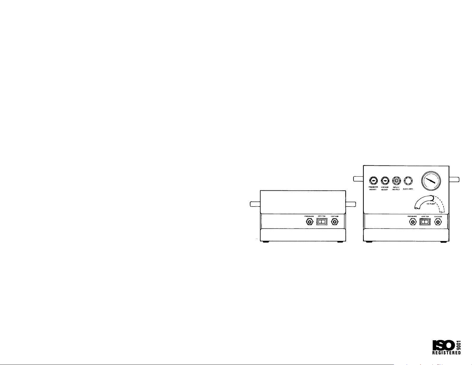
Page 11

To regulate vacuum, turn with screwdriver
until GAUGE shows desired value.
Port for either pressure or vacuum application.
Connect inlet tubing to this port. Polyethylene
fitting accepts 3/16 to 3/8 in I.D. flexible tubing.
Auxiliary input/output port for drawing a vacuum or pressurizing with 2 lines simultaneously.
Accommodates any tube fitting with standard
1/4 in (M) NPT pipe thread.
Dual-function gauge reads either vacuum (to 30
in Hg) or pressure (to 30 psig).
VACUUM/PRESSURE TUBING (9 in long) is permanently connected to pump. Other end has
Quick-Connect/Disconnect Coupler for changing to either VACUUM inlet or PRESSURE outlet
port.
Squeeze Quick-Connect/Disconnect Coupler to
attach or detach the VACUUM/PRESSURE TUBING for vacuum operation.
Squeeze Quick-Connect/Disconnect Coupler
to attach or detach the VACUUM/PRESSURE
TUBING for pressure operation.
Use Quick-Connect/Disconnect Coupler to
attach your service to either the VACUUM or
PRESSURE port.
To regulate pressure, turn with screwdriver
until GAUGE shows desired value.
Press to
start or
stop pump.
Press to
start or
stop pump.
PRESSURE
ADJUST
PRESSURE VACUUMOFF/ON
VACUUM
ADJUST
INPUT/
OUTPUT AUXILIARY
TO PUMP
470-5942
475-3010
PRESSURE OFF/ON VACUUM
 Loading...