

Page 1
OPERATING MANUAL
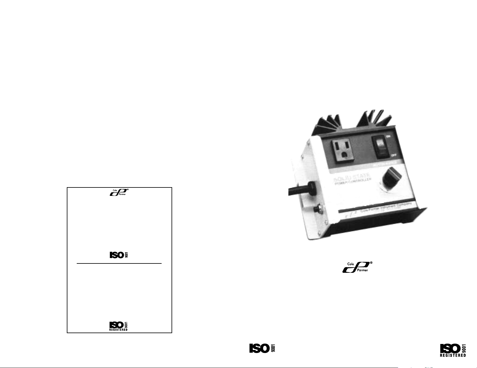
SOLID-STATE AC POWER CONTROLLER
MOTOR-RATED
COLE PARMER MODEL NO. 2604-00
BARNANT MODEL NO. 800-1302
Cole-Parmer Instrument Company
1-800-323-4340 (U.S. and Canada only)
11 (847) 549-7600 (outside U.S.)
(847) 549-7600 (Local)
www.coleparmer.com
Barnant Company
1-800-637-3739 (U.S. and Canada only)
11 (847) 381-7050 (outside U.S.)
(847) 381-7050 (Local)
www.barnant.com
A-1299-0244
Edition 05
Printed in U.S.A.
050802
Cole-Parmer Instrument Co.
625 East Bunker Court
Vernon Hills, Illinois U.S.A. 60061-1844
1-800-323-4340 (U.S. and Canada only)
11(847) 549-7600 (Outside U.S.)
(847) 549-7600 (Local)
FAX (847) 247-2929 (U.S. and Canada only)
11(847) 549-1700 (Fax outside U.S.)
www.coleparmer.com
e-mail:techinfo@coleparmer.com
Barnant Company
28W092 Commercial Ave.
Barrington, Illinois U.S.A. 60010-2392
1-800-637-3739 (U.S. and Canada only)
11(847) 381-7050 (outside U.S.)
(847) 381-7050 (Local)
11(847) 381-7053 (Fax outside U.S.)
(847) 381-7053 (Local fax)
www.barnant.com
e-mail:barnant@barnant.com
SUPPLIER CERTIFIED
SUPPLIER CERTIFIED
Page 2

WARRANTY
The Manufacturer warrants this product to be free from significant
deviations from published specifications. If repair or adjustment is
necessary within the warranty period, the problem will be corrected at
no charge if it is not due to misuse or abuse on your part as determined
by the Manufacturer. Repair costs outside the warranty period, or those
resulting from product misuse or abuse, may be invoiced to you.
The warranty period for this product is noted on the Warranty Card.
PRODUCT RETURN
To limit charges and delays, contact the seller or Manufacturer for
authorization and shipping instructions before returning the product, either
within or outside of the warranty period. When returning the product,
please state the reason for the return. For your protection, pack the
product carefully and insure it against possible damage or loss. Any damages resulting from improper packaging are your responsibility.
TECHNICAL ASSISTANCE
If you have any questions about the use of this product, contact the
Manufacturer or authorized seller.
7
TABLE OF CONTENTS
Title Page
SAFETY PRECAUTIONS . . . . . . . . . . . . . . . . . . . . . . . . . . . . . . . . . . . 3
INTRODUCTION . . . . . . . . . . . . . . . . . . . . . . . . . . . . . . . . . . . . . . . . . .4
GENERAL . . . . . . . . . . . . . . . . . . . . . . . . . . . . . . . . . . . . . . . . . . . . . . 4
APPLICATION DATA . . . . . . . . . . . . . . . . . . . . . . . . . . . . . . . . . . . . . . 4
INSTALLATION . . . . . . . . . . . . . . . . . . . . . . . . . . . . . . . . . . . . . . . . . . .5
OPERATION . . . . . . . . . . . . . . . . . . . . . . . . . . . . . . . . . . . . . . . . . . . . .5
FAIL-SAFE OPERATION . . . . . . . . . . . . . . . . . . . . . . . . . . . . . . . . . . . .5
MAINTENANCE/SERVICE . . . . . . . . . . . . . . . . . . . . . . . . . . . . . . . . . .5
SPECIFICATIONS . . . . . . . . . . . . . . . . . . . . . . . . . . . . . . . . . . . . . . . . .6
WARRANTY . . . . . . . . . . . . . . . . . . . . . . . . . . . . . . . . . . . . . . . . . . . . .7
PRODUCT RETURN . . . . . . . . . . . . . . . . . . . . . . . . . . . . . . . . . . . . . . .7
TECHNICALASSISTANCE . . . . . . . . . . . . . . . . . . . . . . . . . . . . . . . . . .7
Trademarks bearing the ® symbol in this publication
are registered in the U.S. and in other countries.
Page 3

SAFETY PRECAUTIONS
We give the following suggested practices to ensure safe and reliable
installation and success.
If you are uncertain as to the meaning of these Precaution statements or
are otherwise uncertain as to the limits of safe application, consult your
dealer for technical advice before proceeding.
DANGERS: Always provide ancillary protection device such as a
fuse or circuit breaker to the electrical load being controlled. It is possible, for example, that the controller may
be inadvertently programmed to deliver “100%” Power
(about 11 amperes) where only “20%” (about 2 amperes)
would represent a safe continuous rating. In this example, the application of excess power to a heating mantle
could result in excess temperatures which could result
in an unsafe condition due to fire hazard, an unexpected
or premature chemical reaction, or a whole host of other
problems.
Avoid applications where spillage, soaking, immersing,
or excess liquid come in contact with the controller and
its power outlet socket.
WARNING: There are no user serviceable parts in this solid-state
controller. If repairs are required, contact your dealer.
CAUTIONS: Avoid any temperature or electrical environment outside
of the recommended ranges given in this manual.
If temperature control is desired, but cannot be safely
obtained by manual techniques, we recommend the use
of a “fail-safe” controller with a feedback temperature
sensor such as the COLE-PARMER Series 2155/2186
Temperature Controllers.
This controller is not intended to be used with
Fluorescent lighting or with other electrical arc discharge devices.
3
SPECIFICATIONS
Output Voltage
Control Range: 2–98% of input voltage at maximum rated
load of 11A
(single turn potentiometer)
Max. Load Current: 15A (Intermittent)
(At 23°C Amb.): 11A (Continuous)
Max. Continuous Watts: 1265
Circuit Breaker: 15A
Power: 115V AC +/– 15V AC, 60 Hz
Furnished with 6-ft. 3-wire, grounded
line cord
Environmental
Temperature,
Operating: 0°C to 40°C (32°F to 104°F)
Storage: –25°C to 65°C (-13°F to 149°F)
Construction: Aluminum enclosure, baked epoxy,
heavy-duty heat sink
Dimensions: 6 in W x 5-3/8 in D x 3-1/2 in H
6
Page 4

5
INTRODUCTION
This Power Controller is intended to be used in a variety of experimental,
process laboratory and engineering applications involving the controlled
delivery of significant amounts of AC (Alternating Current) power to heating mantles, heating tapes, various controllable light sources, AC induction
and “Universal” motors. When properly used and applied, this controller will
perform dependably for thousands of hours.
GENERAL
All solid-state circuitry means reliable, trouble-free operation—no wearprone relays or heat-generating power resistors. Handsome, compact
design and easy to operate. Rubber feet permits use as a portable controller. Range of control is 2 to 98% of input voltage. Its output is protected
through a circuit breaker. The unit is motor-rated and designed to comply
with UL Standard For Safety 244A for Solid-State Controls for Appliances.
APPLICATION DATA
Precise voltage and power control permits use of fixed speed AC induction
motors in variable speed applications. This controller meets rigid standards
for regulating power to all kinds of laboratory and industrial devices, this
includes universal motors up to 1/2 hp.
The unit is also ideal for controlling immersion heaters and high intensity
lamps (up to 1265 watts), plus flexible electric heating tapes. The new heat
sink design provides optimum heat dissipation.
The separate voltage and ON/OFF controls prevent the output voltage setting from being affected when the unit is turned ON and OFF. This is an
advantage in applications requiring a fixed startup voltage.
CAUTION: This controller is not intended to be used with Fluorescent
lighting or with other electrical arc discharge devices.
4
INSTALLATION
Plug the grounded power cord into a 115V AC outlet.
Plug in the cord from the controlled device at the standard 15 ampere
receptacle.
The controller is furnished with mounting hardware and a TEMPLATE for
easy, permanent wall or counter mounting.
OPERATION
The output voltage control dial is graduated from 0 to 100 for reference
purposes. Where high precision isn’t essential, the dial graduations are
close to percentage values for voltage output. When used in precision
motor speed control applications, read the speed with a tachometer as you
adjust the controller.
Here’s the simple operating procedure:
• Press the POWER SWITCH to the ON position. The built-in pilot light
will denote the ON status.
• Adjust the output voltage control dial to the desired level.
FAIL-SAFE OPERATION
An overload condition will automatically shut down the controller.
Note: The pilot light will remain on when the circuit breaker trips.
• Correct the problem, then press the circuit breaker button (located on
the left side) to restore operation.
MAINTENANCE/SERVICE
The rugged enclosure is resistant to standard cleaners and solvents.
WARNING: There are no user serviceable parts in this solid-state
controller. If repairs are required, contact your dealer.
 Loading...