

Page 1
Installation and Operating Instructions
Ultra-Quiet Lab Compressors
Models 22222-29, -30
1065Y4_M_Lab Compressors_22222-29,-30.indd 1 12/22/2017 2:09:02 PM
Page 2

Contents
Important information
1 Documentation . . . . . . . . . . . . . . . . . . . .3
1.1 Warnings and symbols . . . . . . . . . . . . .3
2 Safety. . . . . . . . . . . . . . . . . . . . . . . . . . . . 3
2.1 Intended use . . . . . . . . . . . . . . . . . . . . . .3
2.2 Incorrect use . . . . . . . . . . . . . . . . . . . . . .3
2.3 General safety notes . . . . . . . . . . . . . . .4
2.4 Qualified personnel . . . . . . . . . . . . . . . . 4
2.5 Protection against electrical current . . .4
2.6 Only use original parts. . . . . . . . . . . . . .4
2.7 Transportation and storage . . . . . . . . . .4
2.8 Disposal. . . . . . . . . . . . . . . . . . . . . . . . . .4
Product description
3 Overview . . . . . . . . . . . . . . . . . . . . . . . . .5
3.1 Units with a membrane-drying
unit (115 V) . . . . . . . . . . . . . . . . . . . . . . . .5
3.2 Replacement parts . . . . . . . . . . . . . . . . . 5
4 Technical data . . . . . . . . . . . . . . . . . . . . .5
4.1 Units with a membrane-drying
unit (115 V) . . . . . . . . . . . . . . . . . . . . . . . .5
4.2 Pressure receiver . . . . . . . . . . . . . . . . . . 6
4.3 Declaration of conformity for machines
in accordance with the 2006/42/EC
Directive . . . . . . . . . . . . . . . . . . . . . . . . .6
5 Function. . . . . . . . . . . . . . . . . . . . . . . . . . 7
5.1 Units with membrane drying unit. . . . .8
Mounting
6 Prerequisites . . . . . . . . . . . . . . . . . . . . . .9
6.1 Area of installation . . . . . . . . . . . . . . . . .9
6.2 Pressure receiver test. . . . . . . . . . . . . . .9
7 Operation . . . . . . . . . . . . . . . . . . . . . . . .9
7.1 Remove the packaging. . . . . . . . . . . . . . 9
7.2 Fit the spacer. . . . . . . . . . . . . . . . . . . . . . 9
7.3 Set up compressed air connection . . . .9
7.4 Condensate . . . . . . . . . . . . . . . . . . . . . . 10
7.5 Electrical installation . . . . . . . . . . . . . .10
7.6 Motor protection. . . . . . . . . . . . . . . . . . 10
7.7 Overtemperature protection . . . . . . . . 10
Usage
8 Instructions for use. . . . . . . . . . . . . . . . 11
8.1 Switch the unit on/off . . . . . . . . . . . . . . 11
8.2 Pressure regulator adjustment . . . . . . 11
9 Maintenance . . . . . . . . . . . . . . . . . . . . . 12
9.1 Maintenance plan. . . . . . . . . . . . . . . . . 12
9.2 Preparations when replacing a filter. . 13
9.3 Change the air intake filter. . . . . . . . . . 13
9.4 Replacing the filter of the
membrane-drying unit. . . . . . . . . . . . . 14
Troubleshooting
10 Tips for Operators and Technicians. . . 15
2
1065Y4_M_Lab Compressors_22222-29,-30.indd 2 12/22/2017 2:09:02 PM
Page 3
Important information
1 Documentation
These assembly and operating instructions
form an integral part of the unit. They correspond to the particular model of the unit and
to the technical standards applicable at the
time it was brought to market.
In the event that the instructions and information in these assembly and operating
instructions are not observed, Cole-Parmer
undertakes to provide no warranty and
accepts no liability of any kind for the safe
and reliable operation of the unit.
1.1 Warnings and symbols
Warnings
The warnings in this document are there
to point out possible injury to persons or
damage to machinery.
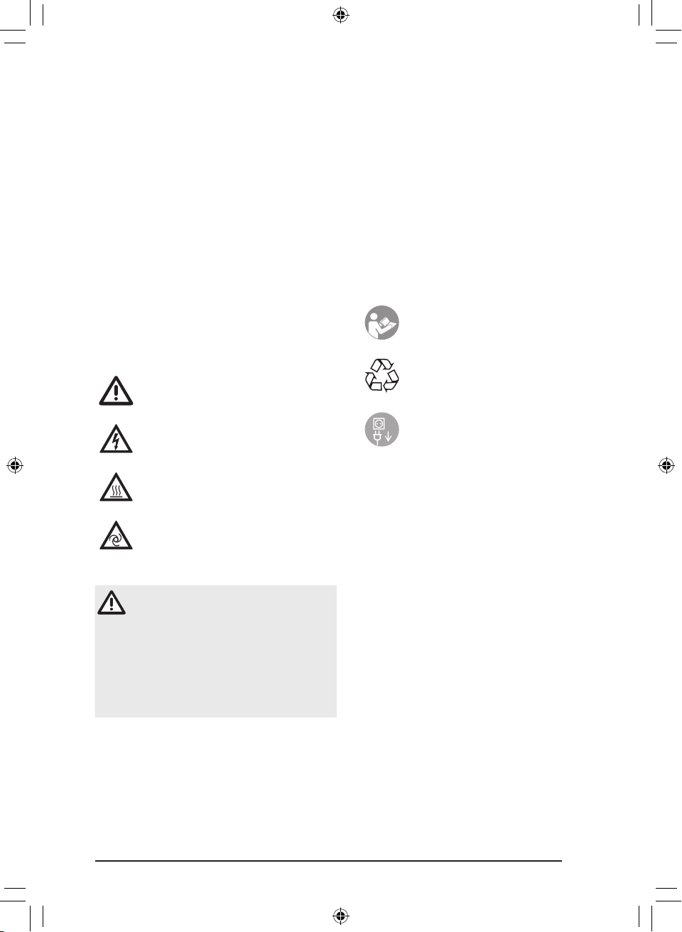
The following warning symbols are used:
General warning symbol
The signal word indicates one of the four
danger levels of the warnings:
DANGER: Immediate danger of serious or
fatal injury
WARNING: Possible danger of serious or
fatal injury
CAUTION: Danger of minor injury
WARNING: Danger of extensive material
damage
Other symbols
These symbols are used in the document
and on the unit itself:
Observe the accompanying
documentation.
Dispose of the unit properly and in
accordance with applicable national,
regional and local laws.
Warning – dangerous electrical
voltage
Warning – high temperatures
Warning – the unit starts up
automatically
The warnings are structured as follows:
SIGNAL WORD
Description of the type and source of
danger
The possible consequences from
disregarding the warning are listed
here
– Observe these measures in order to
avoid the danger.
Switch off the unit (i.e. unplug and
disconnect from mains).
2 Safety
Cole-Parmer has designed and developed
the unit in such a way that danger is to a
large extent excluded if the unit is used as
intended. However, residual risks may be
present. Therefore, please observe the
following information.
2.1 Intended use
The unit is designed for compressing atmospheric air ans is designed to be operated in
dry, ventilated rooms. The unit must not be
operated in wet or damp environments. Use
of the unit in the proximity of gases or combustible liquids is prohibited. Ensure that
mobile units are stationary before operation.
2.2 Incorrect use
Any use of this unit above and beyond that
specifically described in these instructions
will be deemed to be as not according to the
intended use. The manufacturer cannot be
held liable for any damage resulting from
incorrect usage. The user bears all risks.
3
1065Y4_M_Lab Compressors_22222-29,-30.indd 3 12/22/2017 2:09:03 PM
Page 4
WARNING
Serious injury and material damage
due to improper usage
– Conveying explosive mixtures in
any way other than that specified
is not permitted.
2.3 General safety notes
– Before using the unit observe any and all
guidelines, laws, regulations and other
restrictions which may apply to the unit.
– Before each use check the function and
condition of the unit.
– Do not convert or change the unit in
any way.
– Observe the Installation and Operating
Instructions precisely.
– Keep the Installation and Operating
Instructions in an accessible place so that
the operator has instant access to them.
2.4 Qualified personnel
Instructions for use
Persons who operate the unit must, on the
basis of their training and knowledge,
ensure safe and correct handling of the unit.
– Ensure personnel are trained in the correct
usage of the unit.
Installation and repair
– Assembly and installation work, readjust-
ments, modifications, upgrades and
repairs must be carried out by Cole-Parmer
or personnel authorised and trained by
Cole-Parmer.
2.7 Transportation and storage
The unit is shipped in a cardboard box filled
with packaging padding. This packaging
ensures that the unit is optimally protected
in transit. As much as possible, always use
the original packaging for transporting or
storing the unit.
– Keep packaging away from children.
WARNING
Explosion of the pressure receiver
and pressure hoses
Serious personal injury and
material damage
– Ensure that the air has been
evacuated from the pressure
receiver and pressure hoses when
they are stored and transported.
– Protect the unit against moisture
during transit.
– Always transport the unit in an
upright position.
– Only transport the unit using the
transport handles provided.
The unit may be stored in its original
packaging:
– in warm, dry and dust-free rooms;
– protected from contaminants.
If possible, retain the packaging
material.
2.5 Protection against electrical current
– Observe all electrical safety regulations
when working on the unit.
– Replace any damaged lines and plug and
socket outlets immediately.
2.8 Disposal
Unit
Dispose of the unit properly and
in accordance with applicable
national, regional and local laws.
2.6 Only use original parts
– Only use parts and accessories that are
specified or approved by Cole-Parmer.
– Only use original wear parts and spare
parts.
Cole-Parmer accepts no liability for damage
resulting from the use of non-approved
accessories, special accessories or any wear
parts or spare parts other than original parts.
4
1065Y4_M_Lab Compressors_22222-29,-30.indd 4 12/22/2017 2:09:03 PM
Packaging
Dispose of packaging material in
an environmentally responsible
manner.
– Note current disposal routes.
– Keep packaging away from children.
Page 5
Product description
3 Overview
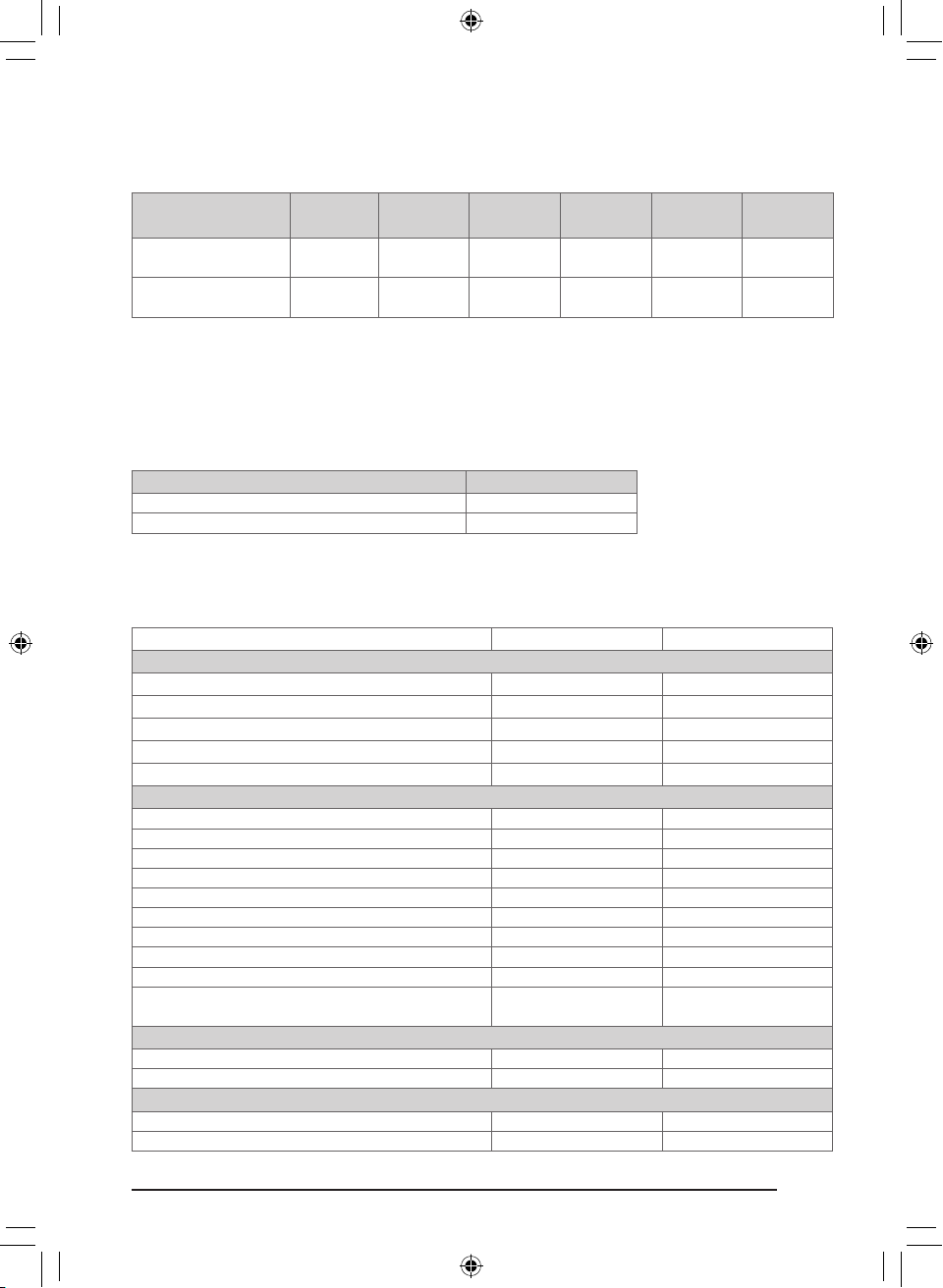
3.1 Units with a membrane-drying unit (115 V)
Description
Ultra-quiet lab
compressor, 36 L/min
Ultra-quiet lab
compressor, 67 L/min
l Included
Not included
Catalog
number
22222-29
22222-30
Air intake
filter
l l l
l l l
Sinter filter
3 µm fine
filter
0.01 µm fine
filter
Activated
carbon filter
3.2 Replacement parts
Replacement parts for units with a membrane-drying unit. The following parts need to be
replaced at the specified maintenance intervals (see "9.1 Maintenance plan").
Replacement parts
Air intake filter (4)
3 mm fine filter (for membrane-drying unit)
Catalog number
22222-34
22222-33
4 Technical data
4.1 Units with a membrane-drying unit (115 V)
Catalog number 22222-29 22222-30
Electrical data
Electrical frequency 60 Hz 60 Hz
Nominal voltage 115 V 115 V
Rated power 0.56 kW 1.15 kW
Nominal current 5.6 A 11.8 A
Mains fusing 6.2 A 13.0 A
General data
Pressure receiver volume 6.6 gal. (25 L) 6.6 gal. (25 L)
Delivery at 60 Hz and 72.5 psi (5 bar) 9.5 GPM (36 L/min) 17.7 GPM (67 L/min)
Delivery at 60 Hz and 101.5 psi (7 bar) 7.9 GPM (30 L/min) 14.3 GPM (54 L/min)
Duty cycle 100% (S1) 100% (S1)
Switch-on / cut-off pressure 87 / 116 psi (6 / 8 bar) 87 / 116 psi (6 / 8 bar)
Safety valve, maximum permissible operating pressure 145 psi (10 bar) 145 psi (10 bar)
Pressure dew point (according to DIN ISO 8573-1) 3 4
Noise level 49 dB(A) 53 dB(A)
Weight 170 lb (77 kg) 192 lb (87 kg)
Dimensions (L x W x H)
Ambient conditions during operation
Temperature 41 to 104°F (5 to 40°C) 41 to 104°F (5 to 40°C)
Humidity Max 95% RH Max 95% RH
Ambient conditions during storage and transport
Temperature –13 to 131°F (–25 to 55°C) –13 to 131°F (–25 to 55°C)
Humidity 10 to 90% RH 10 to 90% RH
20" x 22.8" x 25.7"
(510 x 580 x 653 mm)
20" x 22.8" x 25.7"
(510 x 580 x 653 mm)
5
1065Y4_M_Lab Compressors_22222-29,-30.indd 5 12/22/2017 2:09:03 PM
Page 6

4.2 Pressure receiver
Pressure receivers from Behälter-Werk Burgau GmbH are installed in the unit.
Max operating pressure PS in 145 psi (10 bar)
Vessel volume 6.6 gal. (25 L)
Application Pressure vessel for stationary systems
Corrosion allowance 0" (0 mm)
Maximum temperature 212°F (100°C)
Minimum temperature 14°F (–10°C)
Medium Air/nitrogen
Applied standards ASME Code, Section VIII Div. 1
The pressure receiver has been manufactured as a single component without safety equipment. The pressure receiver may only be within the limits of the purpose of use and technical
data described above. Any use other than as indicated is not permitted for reasons of safety.
The receiver has been designed for predominantly static internal compressive stress.
4.3 Declaration of conformity for machines in accordance with
the 2006/42/EC Directive
We hereby declare that the machine complies with the requirements
of the Directive cited above and the requirements of the following
additional directives:
– Electromagnetic Compatibility (EMC) Directive 2004/108/EC
– Simple pressure vessel directive 2009/105/EC in its current version
– RoHS directive 2011/65/EU
We hereby declare that the machine must not be commissioned until it
has been established that the machine into which this machine is to be
installed complies with the provisions as set out in Machinery Directive
2006/42/EC.
The following harmonized standards and other standards have been
applied:
DIN EN 1012-1:2011-02
DIN EN 60034-1: 2011-02
DIN EN 60034-5: 2007-09
DIN EN 60335-1:2012-10
DIN EN 61000-6-2:2006-03
DIN EN 61000-6-3:2011-09
DIN EN 60204-1:2007-06
DIN EN ISO 12100:2011-09
Bietigheim-Bissingen, 08/18/2014
6
1065Y4_M_Lab Compressors_22222-29,-30.indd 6 12/22/2017 2:09:03 PM
Page 7

5 Function
8
9
10
12 13
4
14
5
15
16
17
11
7
3
Top view (without unit cover)
1) Pressure receiver
2) Safety valve
3) Pressure switch
4) Air intake filter
5) Membrane-drying unit
6) Activated carbon filter (not included on
115 V models)
7) Operating time counter
6
12
Front view
8) Quick-release coupling (regulated)
9) On/off switch
10) Green "Standby mode" indicator lamp
11) Green "Compressor running" indicator
lamp
12) Red "Overheat" warning lamp
13) Unit cover lock
14) Unit cover
15) Pressure gauge
16) Transport handle
17) Pressure regulator
18
19
Rear view
1065Y4_M_Lab Compressors_22222-29,-30.indd 7 12/22/2017 2:09:04 PM
18) Compressed-air connection (plug-in
connection ∅10 mm) (unregulated)
19) Inlet connector with fuses
7
Page 8

5.1 Units with membrane-drying unit
The unit draws in atmospheric air and
compresses it. It then transports the oil-free
compressed air to the membrane-drying
unit. The cooler and the membrane dryer
extract any moisture from the compressed
air. The oil-free, hygienic and dry air is made
available to the consumers in the pressure
receiver.
If compressed air is removed for a
consumer, the receiver pressure drops.
When the switch-on pressure has been
reached, the unit is automatically switched
on again via the pressure switch. When the
cut-off pressure has been reached, the unit
is automatically switched off. A safety valve
prevents the maximum permissible receiver
pressure from being exceeded.
8
1065Y4_M_Lab Compressors_22222-29,-30.indd 8 12/22/2017 2:09:04 PM
Page 9

Mounting
22
22
6 Prerequisites
6.1 Area of installation
The installation area must fulfill the
following requirements:
– Closed, dry, well ventilated room.
– Not a purpose-built room (e. g. heating
or wet room).
– Install the unit on a clean, level and
sufficiently stable surface (take the weight
of the unit into account).
– Install or fit the unit so that the type plate
is easily read and the unit is easily
accessible for operation and maintenance.
– Install the unit so that the socket outlet to
which the unit is connected is easily
accessible.
– Room temperature: 41 to 104°F (5 to 40°C).
– Ensure that a sufficient distance to the wall
is maintained, so that the air can flow in
and out without any obstruction.
Note: The air is filtered during the intake. The
composition of the air is not affected in the
process. The air taken in should be free of
harmful substances (e.g. do not draw in air
from a basement garage or from directly
next to a suction machine).
7 Operation
7.1 Remove the packaging
For safe transportation, the unit is securely
protected with packaging material.
– Remove the packaging material.
– Remove the protective film.
– Check the unit for damage in transit.
– Only lift the unit using the transport
handles and/or from the floor.
7.2 Fit the spacer
– Fit the spacer (22) to the back of the unit to
guarantee ventilation (leave the spacer in
place throughout the service life of the
unit).
NOTICE
Risk of overheating due to
insufficient ventilation
The unit produces heat. This can
lead to heat damage and/or to a
reduction in the service life of the
unit.
– Do not cover the unit.
– Air must be able to flow in and
out unobstructed.
– Ventilation openings must be
sufficiently large.
– For installed units, an independent
ventilation system may be
required in unfavorable cases.
6.2 Pressure receiver test
The operator must comply with the national
directives.
1065Y4_M_Lab Compressors_22222-29,-30.indd 9 12/22/2017 2:09:04 PM
7.3 Set up compressed air connection
The unit has two compressed-air connections. The compressed-air connection on the
operating panel takes the form of a
quick-release coupling. The compressed-air
connection on the back of the unit takes the
form of a plug-in connection. The
compressed-air connections can be used
individually or together.
Quick-release coupling - operating panel
The compressed-air connection to the pres-
sure reducer has a constant pressure (set at
the factory) of 0 to 0 to 87 psi (6 bar), adjustable on the rotary knob.
– Compressed air is extracted at the quick-
release coupling (0.28"/7.2 mm) via a hose
adapter piece on the unit's operating
panel.
– Secure the pressure hose to the hose
adapter piece using a hose clip.
9
Page 10

– Connect the hose adapter piece to the
quick-release coupling.
Plug-in connection - back of unit
The compressed-air connection on the back
of the unit has the unreduced receiver pressure. This varies between 87 and 116 psi (6
and 8 bar) (factory setting). This must be
taken into account when connecting to a
mains line. Any flow from the mains line into
the unit is prevented via an internal check
valve.
– Connect the flexible pressure hose with
plug-in connection (0.39"/10 mm) to the
compressed-air connection on the back of
the unit.
7.4 Condensate
The unit has a vaporization system.
However, at high ambient temperatures
(>86°F/30°C) and at high levels of humidity
(>75% RH), condensate may not be fully
vaporised. Any remaining condensate is
then drained off to the outside via a condensate overflow. In these applications, a
condensate collection tank must be placed
beneath the condensate overflow.
7.5 Electrical installation
– Connect the mains cable to the inlet
connector on the back of the unit.
– Connect the mains cable to a properly
installed socket with PE conductor.
– Lay the mains cable without any
mechanical tension.
– Before commissioning, compare the power
supply voltage to the voltage information
on the type plate.
DANGER
Electric shock due to damaged
mains cable or connector
Electric shocks can cause serious
personal injury
– If the mains cable or connector is
damaged, do not start up the unit.
– Replace the damaged mains
cable.
7.6 Motor protection
The motors in the units are equipped with a
motor protection switch that switches off the
pressure switch in the event of overcurrent.
Overcurrent may be caused by faults (e.g.
blockages). In cases such as these, the cause
of the fault must first be determined and
then eliminated.
Note: The unit can be switched back on
using the rotary knob on the pressure
switch.
– Allow the unit to cool down.
– Switch off the unit.
– Disconnect the mains plug and prevent the
unit from being switched back on again.
– Open the unit lock.
– Remove the unit cover.
– Switch the rotary knob on the pressure
switch back on.
– Refit the unit cover.
7.7 Overtemperature protection
The motors in the units are equipped with a
temperature switch that switches the unit off
if it overheats. In cases such as these, the
cause of the fault must first be determined
and then eliminated.
Note: If the unit is switched off via the
temperature switch, the unit's fan continues
to run.
NOTICE
Automatic unit startup after
cooling down
– Allow the unit to cool down.
10
1065Y4_M_Lab Compressors_22222-29,-30.indd 10 12/22/2017 2:09:04 PM
Page 11

Usage
9
8
9
10
8 Instructions for use
Prior to working on the unit or in
case of danger, disconnect it from
the mains (e. g. pull the plug).
8.1 Switch the unit on/off
11
9) On/off switch
10) Green "Standby mode" indicator lamp
11) Green "Compressor running" indicator
lamp
– The unit is switched on by pressing the
on/off switch (9).
– The unit starts up and the pressure
receiver is filled. The green indicator lamps
(10, 11) light up. Once the cut-off pressure
has been reached, the unit switches off
automatically. The indicator lamp (11)
goes out.
– The unit is switched off by pressing the
on/off switch (9) again. The green indicator
lamp (10) goes out.
8.2 Pressure regulator adjustment
15
17
8) Quick-release coupling
9) On/off switch
15) Pressure gauge
17) Pressure reducer
The pressure regulator (17) regulates the
desired working pressure at the quickrelease coupling (8).
The pressure regulator (17) can be adjusted.
The maximum constant working pressure is
87 psi (6 bar).
Setting the pressure reducer:
The constant working pressure can be
adjusted by turning the pressure regulator
(17). The pressure can be read off the
pressure gauge (15).
– To increase supply pressure: Turn the pres-
sure regulator (17) clockwise towards "+".
– To decrease the supply pressure: Turn the
pressure regulator (17) counterclockwise
towards "-".
Maximum operating pressure 145 psi (10 bar)
Switch-on / cut-off pressure 87 / 116 psi (6 / 8 bar)
11
1065Y4_M_Lab Compressors_22222-29,-30.indd 11 12/22/2017 2:09:04 PM
Page 12

9 Maintenance
De-energize the unit prior to working on it or in the event of potential hazards
(e. g. pull the mains plug) and prevent it from being switched back on again.
9.1 Maintenance plan
Maintenance
interval
Annually
Annually
In accordance
with the respective
national law
Maintenance work
Replace the air intake filter – if there is a high concentration of dust, this must be
carried out every six months (see "9.3 Change the air intake filter")
On units with a membrane-drying unit: Replace the sinter filter in the membrane-drying
unit (see "9.4 Replacing the filter of the membrane-drying unit")
Carry out repeat safety inspections (e.g. pressure receiver inspection, electrical safety
inspection) in accordance with the respective national law.
12
1065Y4_M_Lab Compressors_22222-29,-30.indd 12 12/22/2017 2:09:04 PM
Page 13

9.2 Preparations when replacing a filter
The following steps must first be carried out
before performing maintenance work on the
unit:
– Allow the unit to cool down.
– Switch off the unit.
– Disconnect the mains plug and prevent
the unit from being switched back on
again.
– Evacuate the unit using the blower pistol
(accessory) connected to the quick-release
coupling until the pressure gauge displays
0 psi (0 bar).
– Open the lock on the unit cover.
– Lift up and remove the unit cover.
9.3 Change the air intake filter
5
4
7
6
3
12
4) Air intake filter
– Check that the unit has been disconnected
from power supply and is depressurized.
– Open the cover (1) of the air intake filter
by turning it clockwise.
– Remove the (white) filter element.
– Insert a new filter element.
– Close the cover of the air intake filter by
turning it counterclockwise.
– Fit the unit cover.
13
1065Y4_M_Lab Compressors_22222-29,-30.indd 13 12/22/2017 2:09:05 PM
Page 14

9.4 Replacing the filter of the
membrane-drying unit
– Check that the unit has been disconnected
from the power supply and is
depressurized.
– Unscrew and remove the filter cover.
– Remove the 3 mm fine filter/0.01 mm fine
filter.
– Fit a new 3 mm fine filter/0.01 mm fine filter.
– Replace the filter cover and close.
– Remove the L-shaped screw connection
from the filter housing.
– Unscrew and remove the filter housing.
– Remove the sinter filter.
– Insert a new sinter filter.
– Replace the filter housing and close.
– Fit the unit cover.
5
5) Membrane-drying unit
14
1065Y4_M_Lab Compressors_22222-29,-30.indd 14 12/22/2017 2:09:05 PM
Page 15

Troubleshooting
10 Tips for Operators and Technicians
Repairs above and beyond simple maintenance may only be carried out by a qualified
technician or a Cole-Parmer service technician.
Prior to working on the device or in case of danger, disconnect it from the mains
(e. g. pull the mains plug).
Problem Probable cause Solution
Unit does not start up No mains supply voltage. The
Unit too noisy Mechanical damage Contact customer service.
Unit does not turn
off even though air is
being removed
Output dropping Air intake filter soiled Replace the air intake filter at least once
Water dripping from
air consumers
green "Standby mode" indicator
lamp does not light up
Air intake filter blocked Insert a new air intake filter.
The red "Overheat" warning
lamp lights up
Compressor is overloaded Disconnect the unit from the mains supply and
Leak in the system Check external lines for leaks.
Excessive ambient temperature Ensure that cooling is more effective.
Unsuitable materials drawn in Only convey approved materials.
Defective membrane-drying unit Contact customer service.
Switch on the unit. (The green "Standby mode"
indicator lamp lights up).
Check that the power supply complies with the
specifications on the type plate.
Check the mains plug.
Check the fuses on the inlet connector and
replace them if necessary.
Disconnect the unit from the mains and allow
it to cool down.
Reduce the ambient temperature.
Contact customer service.
allow it to cool down.
Reduce the ambient temperature.
Check that the application is suitable.
Contact customer service.
Contact customer service.
a year. The air intake filter must never be
cleaned.
15
1065Y4_M_Lab Compressors_22222-29,-30.indd 15 12/22/2017 2:09:05 PM
Page 16

Toll-free: 1-800-323-4340
Phone: 1-847-549-7600
Fax: 1-847-247-2929
ColeParmer.com
©2018 Cole-Parmer Instrument Company, LLC.
Warranty
This instrument is warrantied against defects in materials and
workmanship for a period of one (1) year from the date of
invoice. For claims under the warranty, please contact
Cole-Parmer. The warranty does not cover fair wear and tear
of parts or accessories, nor does it apply to improper use,
abnormal operation or insufficient maintenance which is not
in accordance with the instructions in this user manual.
Repairs/return delivery
Ensure that the unit is depressurized before transport!
Use the original packaging when returning units, if possible.
Always pack the units in a plastic bag. Use recyclable packing
material.
Note: If you need to contact Cole-Parmer for troubleshooting
or repairs, please provide the model number and serial
number of the unit.
1065Y4_MAN_22222-29,-30
1065Y4_M_Lab Compressors_22222-29,-30.indd 16 12/22/2017 2:09:05 PM
 Loading...