

Page 1
MODEL 19101-10
Digital Conductivity Meter
Operations Manual
Date:__________________________
Serial No.:_____________________
Dwg. No.:______________________
Calibration By:__________________
COLE PARMER INSTRUMENT COMPANY TEL (847) 549-7600 (800) 323-4340
625 East Bunker Court
Vernon Hills, IL 60061-1844 USA
Printed in U.S.A. 08/98, 04/01
Page 2

TABLE OF CONTENTS
Page
Shipping Checklist .....................................................................3
Cells and Accessories .....................................................................3
Calibration Solutions .....................................................................3
Introduction .....................................................................4
Brief Circuit Description .....................................................................4
Operation .....................................................................4
Placement of Instrument .....................................................................4
Specifications .....................................................................5
Front & Rear Panel Diagram .....................................................................6
Intro to Conductivity .....................................................................7
Power Entry Module .....................................................................7
Calibration .....................................................................8
Calibration Frequency.....................................................................8
Making Measurements .....................................................................8
Cell Constant .....................................................................8
Total Dissolved Solids .....................................................................9
Troubleshooting .....................................................................9
Conductivity Cells .....................................................................9
Cells Continued ...................................................................10
Cleaning Cells ...................................................................10
Micro Flow Cell ...................................................................10
Conductivity Standards ...................................................................11
Reference Literature ...................................................................11
Return of Items ...................................................................11
Maintenance ...................................................................11
Warranty Information ...................................................................12
Calibration Data ...................................................................13
SHIPPING CHECKLIST
Page 3

Upon receipt the instrument should be carefully unpacked and inspected for shipping damage.
All material in the container should be checked against the enclosed packing list. If the
instrument has been damaged in transit, retain all packing material and carton. Contact the
carrier to file a damage claim.
MODEL 19101-10 Packing includes the following:
1- Model 19101-10 Digital Conductivity Meter
1- U.S. Standard Power Cord (removable)
1- Pint 718 µS conductivity standard solution
2- Fuses (1/16 amp) for optional 230 VAC operation
1- Analog Recorder Output Connector
1- Operation Manual
CELLS AND ACCESSORIES
Order Cells separately
Five pin connector Cells with embedded thermistor
Cell constant approximately 10 cm−↑
Au cells are best suited for high purity solutions
Multipurpose cells are combination dip or flow
P/N 01481-62 Dip Cell (Au) with 1 meter (39") cable
P/N 01481-64 Dip Cell (Pt) with 1 meter (39") cable
P/N 19101-50 Multipurpose (Au) with 1 meter (39") cable
P/N 19101-52 Multipurpose (Pt) with 1 meter (39") cable
P/N 01481-66 Micro Flow Cell (cell constant 100 cm−↑)
P/N 19100-50 Cell Connector with 6K Thermistor and 1 meter Cable
(For user fabrication of custom cell)
P/N 01481-11 Platinizing Station for re-platinizing (Pt) cells
(does not include Platinizing Solution)
CALIBRATION SOLUTION
Please see our General Catalog for Conductivity Standards available.
INTRODUCTION
Page 3
Page 4

The Model 19101-10 is a bench top, line power instrument designed for the measurement of
Conductivity covering six ranges from 0 to 199.9 milli Siemens (mS). The bright red 3 ½ digit
L.E.D. display has a floating decimal and indicates whether displayed measurement is in micro
Siemens (µS) or milli Siemens (mS) [note: mho = Siemens].
The meter features two front panel controls, one for selecting the Range (A-F) and one for the
“Calibrate” control adjustment. The Model 19101-10 has a function switch on the rear panel for
selecting ATC On or Off, both referenced to 25°C. A self-test mode allows the user to check the
calibration reference point. The Power E
VAC operation. The recorder output is 1 volt per 1000 counts from a 1 K ohm source. A builtin tilt stand / handle and cell holder are included.
BRIEF CIRCUIT DESCRIPTION
A sine wave voltage is applied to the drive plate of the cell. The amplitude and frequency of this
voltage is determined by the range and function selected. Range selects one voltage for the three
micro Siemen ranges and one for the three milli Siemen ranges. Function selects if this voltage
is constant (A.T.C. off) or varying inversely to temperature (A.T.C. on). This voltage forces a
current through the solution to the sense plate of the cell. This current is converted to a voltage
by the input summing amplifier, then rectified by a phase sensitive synchronous rectifier is then
filtered and scaled with the calibrate control to become the output for recording and the input to
the A to D convertor.
ntry Module (PEM) allows for either 115 VAC or 230
OPERATION
The next section in this manual contains operating information and should be read before
installing and using the instrument. If you have questions, please see page 9 for information on
how to contact the Technical Applications Department at Cole Parmer.
PLACEMENT OF INSTRUMENT
Place the instrument on a dry flat surface. Apply correct power to the instrument. See rear panel
of instrument for power requirement and page 7 for more information on the power entry
module. Do not operate instrument in direct sunlight, extreme temperatures, electromagnetic
fields or in explosive or corrosive atmospheres. Do not allow fluids to run into instrument.
SPECIFICATIONS
Page 4
Page 5

RANGE RESOLUTION FREQUENCY ACCURACY( ± 1 Digit)
A (0 - 1.999 µS) .001 35 Hz ±0.3%
B (0 - 19.99 µS) .01 234 Hz ±0.2%
C (0 - 199.9 µS) .1 234 Hz ±0.1%
D (0 - 1.999 mS) .001 1597 Hz ±0.1%
E (0 - 19.99 mS) .01 1597 Hz ±0.2%
F (0 - 199.9 mS) .1 6274 Hz ±0.3%
Temperature Compensation and Slope
TEMPERATURE SLOPE WITH REFERENCE AT 25°°°°C
5°C 1.88%
10°C 1.91%
15°C 1.94%
20°C 1.97%
25°C------------------------------------------------2.00%
30°C 2.03%
35°C 2.06%
40°C 2.09%
45°C 2.12%
ENVIRONMENTAL LIMITS
5 to 45°C (41 to 113°F)
5 to 90% Relative Humidity
LINE POWER
115/230 VAC 50/60 Hz less than 5 watts
International safety recognized power entry module and transformer can be changed for either
115 VAC or 230 VAC. Instrument is shipped from the factory for 115 VAC operation. Includes
a removable U.S. Standard power cord with IEC 320 connector.
DIMENSIONS
Case size: 6 1/8" W x 2 1/2" H x 6 1/4" D (excludes built-in handle & cell holder)
Instrument weight: ~2.5 lbs.
Shipping weight: ~5.0 lbs
Page 5
Page 6

FRONT & REAR PANEL DIAGRAM
Page 6
Page 7

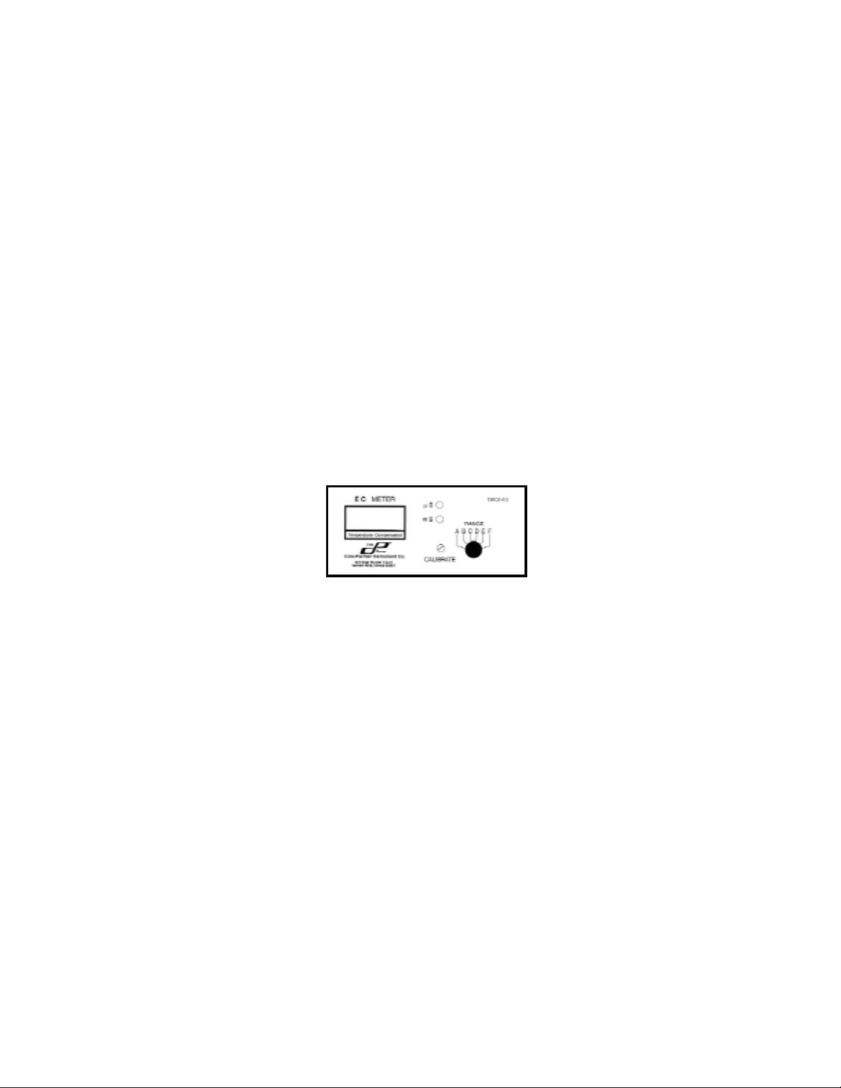
Figure 1 - illustrates the front panel design. Located on the front panel is the display area with
annunciators for µS and mS, a knob for selection of Range and the inset Calibrate control.
Figure 2 - illustrates the rear panel design. Located on the rear panel is the Cell Connector, the
Power Entry Module, a knob for selection of Self Test, ATC on or off and the Recorder Output.
Note: Drawings are for illustration only; not to scale.
Page 7
Page 8

INTRO TO CONDUCTIVITY
The basic unit of resistance is the ohm, conductance is the reciprocal of resistance, its basic unit
of measurement is the mho[_] (also known as Siemens [S]).
The resistance of conductor is inversely proportional to its cross sectional area and directly
proportional to its length. In the measurement of aqueous solution, conductivity is based on the
reciprocal of the resistance of a 1−cm cube of material measured between opposite faces. This
configuration would be a cell with a constant of 1. Conductivity cells usually consist of two
metallic plates of a determined size mounted in a defined area. The cell constant “K” is the
length “L” (or distance between the plates) of the conducting path in centimeters divided by the
effective cross sectional area “A” of the conducting path in square centimeters (K=L/A).
The Model 19101-10 is designed to use a cell with a constant of 10 cm−↑.
Conduction in aqueous solution is by ionic movement and increases with temperature. This
change is expressed in percent per degree Celsius relative to 25°C and is called the slope of the
solution.
The Model 19101-10 has Automatic Temperature Compensation for slope correction.
The Total Dissolved Solids (TDS) in an aqueous solution that provides conduction is not
temperature sensitive as is the conductivity. By multiplying conductivity by an empirical factor,
TDS may be displayed. This empirical factor is determined by the components and temperature
of the solution. When the conductivity has been corrected to 25°C, this factor is usually between
0.5 and 0.7. The Model 19101-10 allows calibration with scale factors as low as 0.45 for direct
display of TDS in parts per million.
POWER ENTRY MODULE
The Model 19101-10 is factory shipped for 115 VAC operation. The international safety
recognized power entry module (PEM) can be changed for either 115 VAC or 230 VAC
operation.
If it is necessary to change the instrument to operate on 230 VAC: Disconnect the power cord
from outlet and instrument. Use a small flat blade screw driver to open the cover (Fuse access
panel) on the power entry module. This should be performed by qualified personnel only. Use
the screw driver to carefully remove the fuse holder. Replace the (2) 1/8 amp fuses with the (2)
1/16 amp fuses supplied with the instrument. Rotate 180° and insert fuse holder into PEM and
with Access Panel door closed, 230 V will appear in window.
Page 8
Page 9

CALIBRATION
Plug in meter and Power On. Plug in Clean Conductivity Cell to connector on Rear Panel.
Supplies Needed: Three Clean Test Tubes or Beakers
Calibration Standard of Known Value
A small Flat Blade Screwdriver
Prepare three samples of calibration solution (1 pint 718 shipped with the instrument or standard
of choice) by pouring a small amount (example: ½ ounce into 19 x 150 mm Tube) of standard
solution into each of the (3) clean test tubes or beakers. Using a clean cell, dip the cell into the
first sample (held at 25°C). Move cell up and down a few times to dislodge any air bubbles.
Withdraw cell and dispose of excess solution by gently shaking off. Do not touch or wipe off
cell. Place the cell into the second sample of solution for a few seconds then withdraw cell and
again shake off excess solution. Place cell into third test tube or beaker. Measurement should be
made after cell is placed into third sample (minimum depth of 1.5"). Now using a small flat
blade screwdriver, set the calibrate control to display the value of your standard solution being
measured (example .718 in D Range).
CALIBRATION FREQUENCY
The Model 19101-10 features a Self-Test mode (Rear panel) which allows the calibration
reference point (cell constant) to be checked. The last page of this manual contains a chart which
can be used for recording calibration data.
MAKING MEASUREMENTS OF UNKNOWN SOLUTIONS
In making measurements of unknown solutions, select F on the front panel Range switch,
Function switch on rear panel set to A.T.C. “On”. Using three samples of the “unknown
solution”, rinse the cell in the first sample of solution. Allow the cell to temperature equilibrate
about 15 seconds. Select the appropriate Range then remove cell and dispose of excess solution
by gently shaking off. Repeat process for second sample of solution. Place the cell in the third
sample for measurement. Record measurement once reading becomes stable.
CELL CONSTANT
By changing the Function switch (on rear panel) to Self-Test and the Range switch (on front
panel) to B, the cell constant may be read directly from the display. The cell constant displayed
should read between 9.00 and 11.0 if using a dip or multipurpose cell. Micro Flow cells have a
cell constant of 100 and all readings displayed should be multiplied by a factor of 10.
Page 9
Page 10

TOTAL DISSOLVE SOLIDS (TDS)
Select the scale factor for TDS of the solution to be measured (example: one gram per liter of
KCl [1000 ppm] will yield a conductivity of 1793 µS (micro Siemens), 1000÷1793 = .55772.
Multiply the scale factor (.55772) by the cell constant previously determined (see page 8 )
Example: .55772 X 10.04 (cell constant) = 5.6. With Function switched to Self-Test and Range
turned to “B”, adjust the front panel calibrate so the display reads the product of the TDS scale
factor and cell constant (5.6).
Make TDS measurements in the appropriate Range with A.T.C. “On” or the solution held at
25°C. The reading of the digital display will be in (ppm) parts per million (Range A, B, & C)
and in (ppt) parts per thousand (Range D, E, & F) of TDS in the solution.
TROUBLE SHOOTING & TECH SUPPORT
If the meter will not calibrate with the standard solution, check to make sure the conductivity cell
is clean and your conductivity standard is not contaminated. If you need Technical Assistance,
please call COLE PARMER at (800) 323-4340 or (547) 549-7600 Monday through Friday.
CONDUCTIVITY CELLS
There are several types of conductivity cells available. The (Au) cell is recommended for
measurements of high purity solutions. The (Au) multipurpose cell in the flow configuration is
recommended for ultra pure water (grab samples of ultra pure water are subject to contamination
from the vessel and atmospheric gases). The (Au) cell has much less tendency to carry over
solution from one measurement to the next. The (Au) cells require less maintenance than the (Pt)
cells since no re-platinizing is required.
The (Pt) cells are needed for measuring solutions with high conductivity readings such as sea
water. The (Pt) cells will require re-platinizing on occasion. Anytime a (Pt) cell is cleaned it
should be re-platinized. This can be accomplished with the Model 01481-11 Platinizing Station
and with (ASTM D1125) Platinizing Solution. The cell may also be shipped to COLE PARMER
for return to the manufacturer for cleaning and re-platinizing (see page 11 for how to return an
item to COLE PARMER).
Page 10
Page 11

CONDUCTIVITY CELLS CONTINUED
It is important to remember that the conductivity cell is delicate and should be cared for properly.
Before using the cell it should be rinsed or soaked in tap or deionized (DI) water if available for
one to two minutes. Carefully, shake off excess solution and dry with a clean lab wipe. If
possible, rinse cell in a sample of the solution to be measured before the actual measurement is
made. Once the cell is placed in the sample for measurement, it is helpful to agitate the cell by
moving up and down and few times. This will aid in dislodging any air bubbles. Allow
sufficient time for temperature equilibration (10 to 15 seconds) before recording measurement.
When finished using the cell, rinse in DI water or an appropriate solvent (see the “cleaning cells”
section below) to remove any residue which has contaminated the plates. Wipe off cell with
clean lab wipe and store dry.
For convenience, the Model 19101-10 includes a built-in cell holder. An o-ring on the
conductivity dip or multipurpose cell allows the cell to be vertically positioned in the cell holder.
CLEANING CELLS
To clean a conductivity cell, wet a cotton tipped applicator with a solvent appropriate to remove
any residue that has contaminated the plates of the cell. Choose a solvent (ie: Isopropanol 99%)
that will not damage the epoxy tube the cell is constructed of (do not use Aqua Regia to clean
cell or remove old platinum). Insert the wetted swab through the cell. You may need to do this
several times until the swab shows no residue. Then clean with a mild detergent and warm DI
water. Remember, if it is a platinum (Pt) cell, it will need to be re-platinized after it has been
cleaned. Clean the Cell only when necessary. See the “maintenance” section on page 11 for
more information.
MICRO FLOW CELL
When using the P/N 01481-66 Micro Flow Cell which has a cell constant of 100, all displayed
readings must be multiplied by a factor of 10. Use only non-metallic tubing or fittings for
connections on the stainless steel tubing. The maximum temperature is 50°C and the maximum
recommended pressure is 50 P.S.I. Mount the micro flow cell so that the solution flows upward.
This will help to clear any air bubbles.
Page 11
Page 12

CONDUCTIVITY STANDARDS
One pint of 718 standard calibration solution was included with the meter or choose a Standard
that is close to the range you expect to measure. For example, if measuring DI water or a sample
low in conductivity, use a low standard of 50 to 100 µS. Standards less than 50 µS are easily
contaminated and therefore not always reliable. You can choose from a variety of Conductivity
Standards available or make your own.
Reference Solution Approximate Normality Grams of KCl weighed in Air
@ 25°C of Solution per 1 liter of Solution @ 20°C
1408.8 µS .01 .7440
12856 µS .1 7.4365
111342 µS 1 74.2460
REFERENCE LITERATURE
Standard Methods, 19th Edition ISBN 0-87553-223-3
ASTM Standards, Volume 11.01 ISBN 0-8031-2332-9
RETURN OF ITEMS
Authorization must be obtained from the Customer Service Department at (800) 323-4340 before
returning items for any reason. Should your instrument be in need of repair and has not been
subject to abuse or misuse, please return freight prepaid and adjustments will be made without
charge if under warranty. Out of warranty items will be repaired on a charge basis with customer
approval. The Customer Service Department will issue an R.A.# and instructions for returning
the instrument. Please include any data regarding the reason the item is being returned.
MAINTENANCE
The Model 19101-10 requires no general maintenance. Occasional cleaning may be done with a
damp cloth and a mild detergent. Do not allow fluids to run into the instrument. Conductivity
cells should be cleaned and inspected periodically and replaced when necessary.
Page 12
Page 13

WARRANTY
COLE PARMER warrants this product to be free from defects in Materials and Workmanship for
a period of one year from date shipped. Warranty will be allowed whenever possible, however
all warranty claims will be reviewed by COLE PARMER INSTRUMENT COMPANY.
EXCLUSIONS FROM WARRANTY
This warranty shall not apply to fuses, disposable batteries, (rechargeable type batteries, pH
electrodes, temperature probes and conductivity cells are warranted for 90 days), or any product
or part which have been subject to misuse, neglect, tampering, accident or abnormal conditions
of operations.
LIMITED WARRANTY
COLE PARMER is pleased to offer suggestions on the use of this product: however, we have no
control over its use or intended use. No representation or warranty, whether of merchantability,
fitness for any particular purpose is made beyond the repair, replacement or refund of purchase
price at the sole discretion of COLE PARMER. In no event shall COLE PARMER, nor the
manufacturer be liable for special or consequential damages for injury to person or property
which may result from the use of this product. Users shall determine the suitability of this
product for its intended applications before using and users shall assume all risk and liability
whatsoever in connection therewith regardless of our suggestions as to applications or
constructions.
RETURN OF ITEMS
Authorization must be obtained from our Customer Service department [call - (800) 323-4340]
before returning any item for any reason. When applying for authorization, please include any
data regarding the reason the item is being returned. All items must be carefully packed as to
prevent shipping damage, and insured against loss and shipping damage. COLE PARMER will
not be responsible for any shipping damage. Items being returned without prior authorization
may not be accepted.
NOTE
COLE PARMER reserves the right to make changes in specifications, designs, construction and
appearance of our products without notice.
Page 13
Page 14

CALIBRATION DATA
Calibrating the instrument with a known calibration solution should be performed periodically.
Calibration frequency (daily, weekly, monthly or ?) is a determination made by the user. Record
data on this form or this form may be copied. Internal calibration should be performed only be
qualified personnel when needed.
Date / Time Standard/ Value µS Lot # / Date Cell K/Ref. Point Initials / Emp.#
Page 14
Page 15

Page 15
 Loading...