

Page 1

Specifications
18200-30
Cole-Parmer Instrument Company
625 East Bunker Court
Vernon Hills, Illinois 60061-1844
(847) 549-7600
(847) 247-2929 (Fax)
800-323-4340
www.coleparmer.com
e-mail: techinfo@coleparmer.com
Document Revision 1.1, August, 2008
© Copyright 2008, Measurement Computing Corporation
Page 2

Specifications
Parameter
Conditions
Specification
A/D converters
Four dual 24-bit, Sigma-Delta type
Number of channels
8 differential
Input isolation
500 VDC minimum between field wiring and
USB interface
Channel configuration
Software programmable to match sensor type
Differential input voltage range
for the various sensor categories
Thermocouple
±0.080 V
RTD
0 to 0.5 V
Thermistor
0 to 2 V
Semiconductor sensor
0 to 2.5 V
Absolute maximum input voltage
±C0x through ±C7x relative to
GND (pins 9, 19, 28, 38)
±25 V power on, ±40 V power off.
Input impedance
5 Gigohm, min.
Input leakage current
Open thermocouple detect
disabled
30 nA max.
Open thermocouple detect
enabled
105 nA max.
Normal mode rejection ratio
f
IN
= 60 Hz
90 dB min.
Common mode rejection ratio
f
IN
= 50 Hz/60 Hz
100 dB min.
Resolution
24 bits
No missing codes
24 bits
Input coupling
DC
Warm-up time
30 minutes min.
Open thermocouple detect
Automatically enabled when the channel pair is
configured for thermocouple sensor.
The maximum open detection time is 3 seconds.
CJC sensor accuracy
15 °C to 35 °C
±0.25 °C typ.,±0.5 °C max.
0 °C to 70 °C
–1.0 to +0.5 °C max
Typical for 25 °C unless otherwise specified.
Specifications in italic text are guaranteed by design.
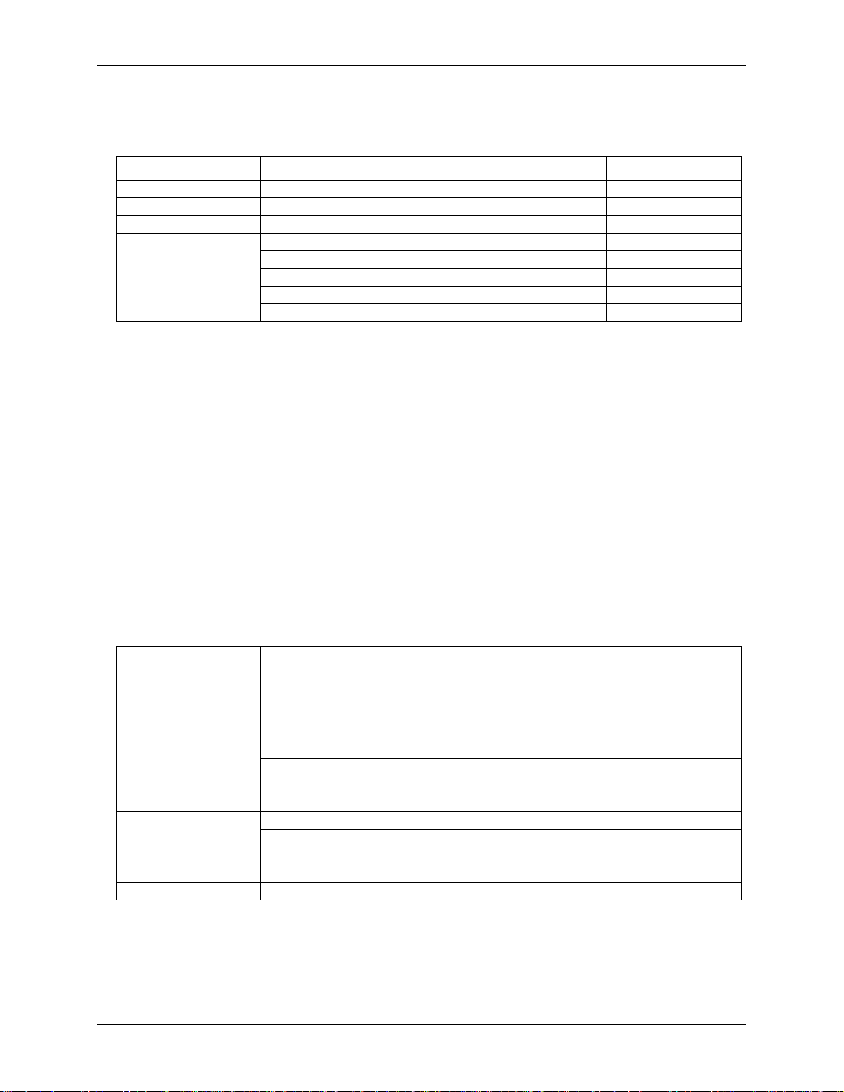
Analog input
Table 1. Generic analog input specifications
1
Page 3
Specifications 18200-30
Sensor Category
Conditions
Specification
Disabled
Thermocouple
8 differential channels
Semiconductor sensor
8 differential channels
RTD and thermistor
2-wire input configuration with a single sensor
4 differential channels
2-wire input configuration with two sensors
8 differential channels
3-wire configuration with a single sensor per channel pair
4 differential channels
4-wire input configuration with a single sensor
2 differential channels
4-wire input configuration with two sensors
4 differential channels
Parameter
Conditions
Thermocouple
J: -210 °C to 1200 °C
K: -270 °C to 1372 °C
R: -50 °C to 1768 °C
S: -50 °C to 1768 °C
T: -270 °C to 400 °C
N: -270 °C to 1300 °C
E: -270 °C to 1000 °C
B: 0 °C to 1820 °C
RTD
100 ohm PT (DIN 43760: 0.00385 ohms/ohm/°C)
100 ohm PT (SAMA: 0.003911 ohms/ohm/°C)
100 ohm PT (ITS-90/IEC751:0.0038505 ohms/ohm/°C)
Thermistor
Standard 2,252 ohm through 30,000 ohm
Semiconductor / IC
TMP36 or equivalent
Channel configurations
Table 2. Channel configuration specifications
Note 1: Internally, the 18200-30 has four, dual-channel, fully differential A/Ds providing a total of eight
differential channels. The analog input channels are therefore configured in four channel pairs
with CH0/CH1 sensor inputs, CH2/CH3 sensor inputs, CH4/CH5 sensor inputs, and CH6/CH7
sensor inputs paired together. This "channel-pairing" requires the analog input channel pairs be
configured to monitor the same category of temperature sensor. Mixing different sensor types of
the same category (such as a type J thermocouple on channel 0 and a type T thermocouple on
channel 1) is valid.
Note 2: Channel configuration information is stored in the EEPROM of the isolated microcontroller by
the firmware whenever any item is modified. Modification is performed by commands issued
over USB from an external application, and the configuration is made non-volatile through the
use of the EEPROM.
Note 3: The factory default configuration is Disabled. The Disabled mode will disconnect the analog
inputs from the terminal blocks and internally ground all of the A/D inputs. This mode also
disables each of the current excitation sources.
Compatible sensors
Table 3. Compatible sensor type specifications
2
Page 4
Specifications 18200-30
Sensor Type
Maximum error
Typical error
Temperature range
J
±1.499 °C
±0.507 °C
-210 to 0 °C
±0.643 °C
±0.312 °C
0 to 1200 °C
K
±1.761 °C
±0.538 °C
-210 to 0 °C
±0.691 °C
±0.345 °C
0 to 1372 °C
S
±2.491°C
±0.648 °C
-50 to 250 °C
±1.841 °C
±0.399 °C
250 to 1768.1 °C
R
±2.653 °C
±0.650 °C
-50 to 250 °C
±1.070 °C
±0.358 °C
250 to 1768.1 °C
B
±1.779 °C
±0.581 °C
250 to 700 °C
±0.912 °C
±0.369 °C
700 to 1820 °C
E
±1.471 °C
±0.462 °C
-200 to 0 °C
±0.639 °C
±0.245 °C
0 to 1000 °C
T
±1.717 °C
±0.514 °C
-200 to 0 °C
±0.713 °C
±0.256 °C
0 to 600 °C
N
±1.969 °C
±0.502 °C
-200 to 0 °C
±0.769 °C
±0.272 °C
0 to 1300 °C
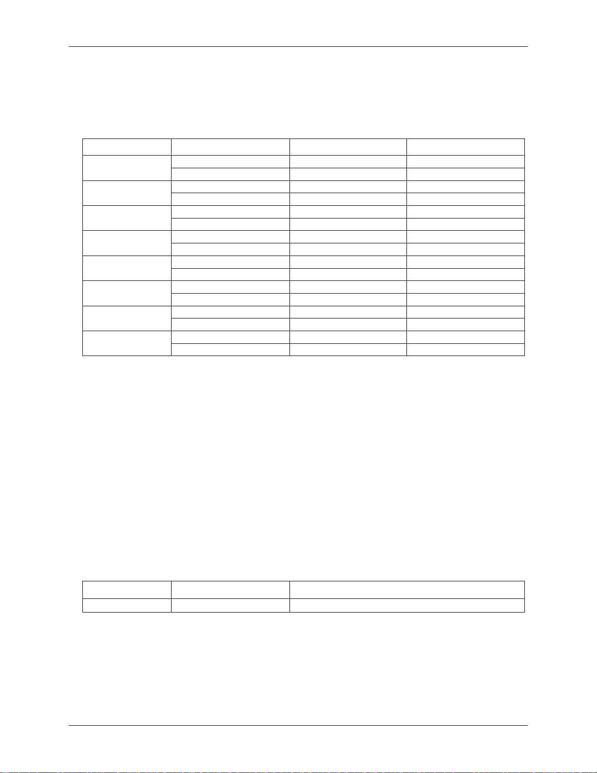
Sensor Type
Temperature Range (°C)
Maximum Accuracy Error
TMP36 or equivalent
-40 to 150 °C
±0.50 °C
Accuracy
Thermocouple measurement accuracy
Table 4. Thermocouple accuracy specifications, including CJC measurement error
Note 4: Thermocouple measurement accuracy specifications include linearization, cold-junction
compensation and system noise. These specs are for one year, or 3000 operating hours,
whichever comes first, and for operation of the 18200-30 between 15 °C and 35 °C. For
measurements outside this range, add ±0.5 degree to the maximum error shown. There are CJC
sensors on each side of the module. The accuracy listed above assumes the screw terminals are at
the same temperature as the CJC sensor. Errors shown do not include inherent thermocouple
error. Please contact your thermocouple supplier for details on the actual thermocouple error.
Note 5: Thermocouples must be connected to the 18200-30 such that they are floating with respect to
GND (pins 9, 19, 28, 38). The 18200-30 GND pins are isolated from earth ground, so connecting
thermocouple sensors to voltages referenced to earth ground is permissible as long as the
isolation between the GND pins and earth ground is maintained.
Note 6: When thermocouples are attached to conductive surfaces, the voltage differential between
multiple thermocouples must remain within ±1.4 V. For best results we recommend the use of
insulated or ungrounded thermocouples when possible.
Semiconductor sensor measurement accuracy
Table 5. Semiconductor sensor accuracy specifications
Note 7: Error shown does not include errors of the sensor itself. These specs are for one year while
operation of the 18200-30 unit is between 15 °C and 35 °C. Please contact your sensor supplier
for details on the actual sensor error limitations.
3
Page 5

Specifications 18200-30
RTD
Sensor
Temperature
Maximum Accuracy Error (°C)
Ix+ = 210 µA
Typical Accuracy Error (°C)
Ix+ = 210 µA
PT100, DIN, US or
ITS-90
-200°C to -150°C
±2.85
±2.59
-150°C to -100°C
±1.24
±0.97
-100°C to 0°C
±0.58
±0.31
0°C to 100°C
±0.38
±0.11
100°C to 300°C
±0.39
±0.12
300°C to 600°C
±0.40
±0.12
Thermistor
Temperature Range
Maximum Accuracy Error (°C)
Ix+ = 10 µA
2252 Ω
-40 to120 °C
±0.05
3000 Ω
-40 to120 °C
±0.05
5000 Ω
-35 to120 °C
±0.05
10000 Ω
-25 to120 °C
±0.05
30000 Ω
-10 to120 °C
±0.05
RTD measurement accuracy
Table 6. RTD measurement accuracy specifications
Note 8: Error shown does not include errors of the sensor itself. The sensor linearization is performed
using a Callendar-Van Dusen linearization algorithm. These specs are for one year while
operation of the 18200-30 unit is between 15 °C and 35 °C. The specification does not include
lead resistance errors for 2-wire RTD connections. Please contact your sensor supplier for details
on the actual sensor error limitations.
Note 9: Resistance values greater than 660 ohms cannot be measured by the 18200-30 in the RTD mode.
The 660 ohm resistance limit includes the total resistance across the current excitation (±Ix) pins,
which is the sum of the RTD resistance and the lead resistances.
Note 10: For accurate three wire compensation, the individual lead resistances connected to the ±Ix pins
must be of equal value.
Thermistor measurement accuracy
Table 7. Thermistor measurement accuracy specifications
Note 11: Error shown does not include errors of the sensor itself. The sensor linearization is performed
using a Steinhart-Hart linearization algorithm. These specs are for one year while operation of the
18200-30 unit is between 15 °C and 35 °C. The specification does not include lead resistance
errors for 2-wire thermistor connections. Please contact your sensor supplier for details on the
actual sensor error limitations. Total thermistor resistance on any given channel pair must not
exceed 180 k ohms. Typical resistance values at various temperatures for supported thermistors
are shown in Table 8.
4
Page 6

Specifications 18200-30
Temp
2252 Ω
thermistor
3000 Ω
thermistor
5 kΩ
thermistor
10 kΩ
thermistor
30 kΩ
thermistor
-40 °C
76 kΩ
101 kΩ
168 kΩ
240 kΩ (Note 12)
885 kΩ (Note 12)
-35 °C
55 kΩ
73 kΩ
121 kΩ
179 kΩ
649 kΩ (Note 12)
-30 °C
40 kΩ
53 kΩ
88 kΩ
135 kΩ
481 kΩ (Note 12)
-25 °C
29 kΩ
39 kΩ
65 kΩ
103 kΩ
360 kΩ (Note 12)
-20 °C
22 kΩ
29 kΩ
49 kΩ
79 kΩ
271 kΩ (Note 12)
-15 °C
16 kΩ
22 kΩ
36 kΩ
61 kΩ
206 kΩ (Note 12)
-10 °C
12 kΩ
17 kΩ
28 kΩ
48 kΩ
158 kΩ
-5 °C
9.5 kΩ
13 kΩ
21 kΩ
37 kΩ
122 kΩ
0 °C
7.4 kΩ
9.8 kΩ
16 kΩ
29 kΩ
95 kΩ
Number of Input Channels
Maximum Throughput
1
2 Samples/second
2
2 S/s on each channel, 4 S/s total
3
2 S/s on each channel, 6 S/s total
4
2 S/s on each channel, 8 S/s total
5
2 S/s on each channel, 10 S/s total
6
2 S/s on each channel, 12 S/s total
7
2 S/s on each channel, 14 S/s total
8
2 S/s on each channel, 16 S/s total
Table 8. Typical thermistor resistance specifications
Note 12: Resistance values greater than 180 k ohms cannot be measured by the 18200-30 in the thermistor
mode. The 180 k ohm resistance limit includes the total resistance across the current excitation
(±Ix) pins, which is the sum of the thermistor resistance and the lead resistances.
Note 13: For accurate three wire compensation, the individual lead resistances connected to the ±Ix pins
must be of equal value.
Throughput rate
Note 14: The analog inputs are configured to run continuously. Each channel is sampled twice per second.
The maximum latency between when a sample is acquired and the temperature data is provided
by the USB unit is approximately 0.5 seconds.
Table 9. Throughput rate specifications
5
Page 7

Specifications 18200-30
Digital type
CMOS
Number of I/O
8 (DIO0 through DIO7)
Configuration
Independently configured for input or output.
Power on reset is input mode.
Pull-up/pull-down configuration
All pins pulled up to +5 V via 47 K resistors (default). Pull-down to ground
(GND) also available.
Digital I/O transfer rate (software paced)
Digital input – 50 port reads or single bit reads per second typ.
Digital output – 100 port writes or single bit writes per second typ.
Input high voltage
2.0 V min., 5.5 V absolute max.
Input low voltage
0.8 V max., –0.5 V absolute min.
Output low voltage (IOL = 2.5 mA)
0.7 V max.
Output high voltage (IOH = –2.5 mA)
3.8 V min.
EEPROM
1,024 bytes isolated micro reserved for sensor configuration
256 bytes USB micro for external application use
Type
Two high-performance 8-bit RISC microcontrollers
Parameter
Conditions
Specification
USB +5V (VBUS) input voltage range
4.75 V min. to 5.25 V max.
Digital input/output
Table 10. Digital input/output specifications
Note 15: All ground pins on the 18200-30 (pins 9, 19, 28, 38) are common and are isolated from earth
ground. If a connection is made to earth ground when using digital I/O and conductive
thermocouples, the thermocouples are no longer isolated. In this case, thermocouples must not be
connected to any conductive surfaces that may be referenced to earth ground.
Memory
Microcontroller
USB +5V voltage
Table 11. Memory specifications
Table 12. Microcontroller specifications
Table 13. USB +5V voltage specifications
6
Page 8

Specifications 18200-30
Parameter
Conditions
Specification
Supply current
USB enumeration
<100 mA
Supply current
(Note 16)
Continuous mode
140 mA typ.
User +5V output voltage range
(terminal block pin 21 and pin 47)
Connected to self-powered hub. (Note 17)
4.75 V min. to
5.25 V max.
User +5V output current
(terminal block pin 21 and pin 47)
Bus-powered and connected to a self-powered hub. (Note 17)
10 mA max.
Isolation
Measurement system to PC
500 VDC min.
USB device type
USB 2.0 (full-speed)
Device compatibility
USB 1.1, USB 2.0
Self-powered, 100 mA consumption max
USB cable type
A-B cable, UL type AWM 2527 or equivalent. (min 24 AWG VBUS/GND,
min 28 AWG D+/D–)
USB cable length
3 meters max.
Power
Table 14. Power specifications
Note 16: This is the total current requirement for the 18200 -30 which includes up to 10 mA for the status
LED.
Note 17: Self-Powered Hub refers to a USB hub with an external power supply. Self-powered hubs allow
a connected USB device to draw up to 500 mA.
Root Port Hubs reside in the PC’s USB Host Controller. The USB port(s) on your PC are root
port hubs. All externally powered root port hubs (desktop PC’s) provide up to 500 mA of current
for a USB device. Battery-powered root port hubs provide 100 mA or 500 mA, depending upon
the manufacturer. A laptop PC that is not connected to an external power adapter is an example
of a battery-powered root port hub.
USB specifications
Table 15. USB specifications
7
Page 9

Specifications 18200-30
Parameter
Conditions
Specification
Configuration
4 dedicated pairs:
±I1 - CH0/CH1
±I2 - CH2/CH3
±I3 - CH4/CH5
±I4 - CH6/CH7
Current excitation output ranges
Thermistor
10 µA typ.
RTD
210 µA typ.
Tolerance
±5% typ.
Drift 200 ppm/°C
Line regulation
2.1 ppm/V max.
Load regulation
0.3 ppm/V typ.
Output compliance voltage
(relative to GND pins 9, 19, 28, 38)
3.90 V max.
-0.03 V min.
Operating temperature range
0 to 70 ° C
Storage temperature range
-40 to 85 ° C
Humidity
0 to 90% non-condensing
Dimensions
127 mm (L) x 88.9 mm (W) x 35.56 (H)
User connection length
3 meters max.
Connector type
Screw terminal
Wire gauge range
16 AWG to 30 AWG
Current excitation outputs (Ix+)
Table 16. Current excitation output specifications
Note 18: The 18200-30 has four current excitation outputs, with ±I1 dedicated to the CH0/CH1 analog
inputs, ±I2 dedicated to CH2/CH3, ±I3 dedicated to CH4/CH5, and ±I4 dedicated to CH6/CH7.
The excitation output currents should always be used in this dedicated configuration.
Note 19: The current excitation outputs are automatically configured based on the sensor (thermistor or
RTD) selected.
Environmental
Table 17. Environmental specifications
Mechanical
Table 18. Mechanical specifications
Screw terminal connector type and pin out
Table 19. Screw terminal connector specifications
8
Page 10

Specifications 18200-30
Pin
Signal Name
Pin Description
Pin
Signal Name
Pin Description
1
I1+
CH0/CH1 current excitation source
27
I4-
CH6/CH7 current excitation return
2
NC 28
GND
3
C0H
CH0 sensor input (+)
29
C7L
CH7 sensor input (-)
4
C0L
CH0 sensor input (-)
30
C7H
CH7 sensor input (+)
5
4W01
CH0/CH1 4-wire, 2 sensor common
31
IC67
CH6/CH7 2 sensor common
6
IC01
CH0/CH1 2-sensor common
32
4W67
CH6/CH7 4-wire, 2 sensor common
7
C1H
CH1 sensor input (+)
33
C6L
CH6 sensor input (-)
8
C1L
CH1 sensor input (-)
34
C6H
CH6 sensor input (+)
9
GND 35
NC 10
I1-
CH0/CH1 current excitation return
36
I4+
CH6/CH7 current excitation source
CJC sensor
CJC sensor
11
I2+
CH2/CH3 current excitation source
37
I3-
CH4/CH5 current excitation return
12
NC 38
GND
13
C2H
CH2 sensor input (+)
39
C5L
CH5 sensor input (-)
14
C2L
CH2 sensor input (-)
40
C5H
CH5 sensor input (+)
15
4W23
CH2/CH3 4-wire, 2 sensor common
41
IC45
CH4/CH5 2 sensor common
16
IC23
CH2/CH3 2 sensor common
42
4W45
CH4/CH5 4-wire, 2 sensor common
17
C3H
CH3 sensor input (+)
43
C4L
CH4 sensor input (-)
18
C3L
CH3 sensor input (-)
44
C4H
CH4 sensor input (+)
19
GND 45
NC
20
I2-
CH2/CH3 current excitation return
46
I3+
CH4/CH5 current excitation source
21
+5V
+5V output
47
+5V
+5V output
22
GND 48
GND
23
DIO0
Digital Input/Output
49
DIO7
Digital Input/Output
24
DIO1
Digital Input/Output
50
DIO6
Digital Input/Output
25
DIO2
Digital Input/Output
51
DIO5
Digital Input/Output
26
DIO3
Digital Input/Output
52
DIO4
Digital Input/Output
Screw terminal pin out
Table 20. Screw terminal pin out
9
Page 11

18200-30-spec.doc
Cole-Parmer Instrument Company
625 East Bunker Court
Vernon Hills, Illinois 60061-1844
(847) 549-7600
Fax: (847) 247-2929
800-323-4340
www.coleparmer.com
E-mail: techinfo@coleparmer.com
 Loading...