

Page 1
heating
OPERATING INSTRUCTIONS
High Performance
Utility Baths
Printed in the U.S.A. 5/01
11. Warranty
OAKTON warrants this bath to be free from significant deviations in material
and workmanship for a period of one year from date of purchase (digital models
12501-00 to -25) or five years from date of purchase (analog models 12500-00 to -35).
If repair or adjustment is necessary and has not been the result of abuse or misuse
within the warrantied time period, please return—freight prepaid—and correction
will be made without charge. OAKTON alone will determine if the product problem
is due to deviations or customer misuse.
Out-of-warranty products will be repaired on a charge basis.
12. Return of items
Authorization must be obtained from our Customer Service Department before
returning items for any reason. When applying for authorization, please include
data regarding the reason the items are to be returned. For your protection, items
must be carefully packed to prevent damage in shipment and insured against possible damage or loss. We will not be responsible for damage resulting from careless or
insufficient packing. Arestocking charge will be made on all unauthorized returns.
NOTE: We reserve the right to make improvements in design, construction, and
appearance of products without notice.
12500-series
www.4oakton.com
Page 2

Table of Contents
1.0 Introduction.....................................................................................................................4
2.0 Receiving and Inspection .............................................................................................4
2.1 Inspection .......................................................................................................................4
2.2 Accessories .....................................................................................................................4
3.0 Installation ...................................................................................................................5-6
3.1 Power Source.................................................................................................................5
3.2 Location ..........................................................................................................................5
3.3 Lifting / Handling........................................................................................................5
3.4 Bath Cover .....................................................................................................................5
3.5 Cleaning .........................................................................................................................6
4.0 Control Panel Overview (Analog Models 12500-00 to 12500-35)............................7
4.1 Power ..............................................................................................................................7
4.2 Temperature Controller................................................................................................7
4.3 Heating Indicator..........................................................................................................7
5.0 Control Panel Overview (Digital Models 12501-00 to 12501-25) .........................8-9
5.1 Power Switch.................................................................................................................8
5.2 Main Temperature Controller......................................................................................8
5.3 Heating Indicator..........................................................................................................8
5.4 Overtemperature Safety Controller............................................................................8
5.5 Safety Indicator..............................................................................................................9
6.0 Operation...................................................................................................................10-12
6.1 Analog Models 12500-00 through 12500-35.......................................................10-11
6.2 Digital Models 12501-00 through 12501-25 ........................................................11-12
7.0 Maintenance...................................................................................................................13
7.1 Cleaning........................................................................................................................13
7.2 Heating Elements........................................................................................................13
8.0 Troubleshooting.......................................................................................................14-16
8.1 Temperature............................................................................................................14-15
8.2 Mechanical ...................................................................................................................16
8.3 Other .............................................................................................................................16
9.0 Parts.................................................................................................................................17
10.0 Specifications..............................................................................................................18
11.0 Wiring Diagrams ..................................................................................................19-20
12.0 Warranty.......................................................................................................................24
13.0 Return of Items...........................................................................................................24
2 3
Page 3

5
3. Installation
Local city, county or other ordinances may govern the use of this equipment. If you
have any questions about local requirements, please contact the appropriate local
agency. Installation may be performed by the end user. It is unnecessary for this unit
to be installed by a technician.
Under normal circumstances this unit is intended for use inside, at room temperatures between 5°C and 40°C, at no greater than 80% relative humidity (at 25°C) and
with a supply voltage that does not vary by more than 10%. Customer Service
should be contacted for operating conditions outside of these limits.
Power Source
The electrical supply to the unit must conform to all national and local electrical
codes. The power source must match the voltage and ampere requirements listed
on the dataplate. Consult the units serial data plate for the voltage and ampere
requirements before making connection. Plug the cord into a grounded outlet.
The voltage of the outlet should not vary more than 10% from the dataplate rating.
A separate circuit is recommended to preclude loss of product due to overloading or
circuit failure.
Location
When selecting a location for this unit, consider all conditions which might affect
performance, such as heat from radiators, ovens, autoclaves, etc. Avoid direct sun,
fast-moving air currents, heating/cooling ducts and high-traffic areas. Allow a
minimum of 5 cm between the unit and surrounding walls and partitions which
might obstruct free air flow.
Lifting / Handling
These units may be heavy for some people and care should be taken to use appropriate lifting devices that are sufficiently rated for these loads. Units should only be
lifted from their bottom surfaces. Handles and knobs are not adequate for lifting or
stabilization. The unit should be completely restrained from tipping during lifting
or transport. All moving parts, such as racks and covers should be removed and
doors need to be positively locked in the closed position during transfer to prevent
shifting and damage.
Gable Cover
Using the gable cover will accelerate heat-up time, ensure stability, and reduce evaporation. The cover must be used to reach set points above 60°C. Note that the cover
is not designed to be air tight or create a pressurized environment.
4
1. Introduction
Thank you for purchasing an OAKTON®StableTemp®Bath. These units are general
purpose water baths for professional, industrial or educational use where the preparation or testing of materials is done at approximately atmospheric pressure and no
flammable, volatile, or combustible materials are being heated. These units are not
intended for hazardous or household locations or use.
Your satisfaction and safety require a complete understanding of this unit. Read the
instructions thoroughly and be sure all operators are given adequate training before
attempting to put the unit in use. Note that this equipment must be used only for its
intended application; any alterations or modifications will void your warranty.
See back page of this manual for more warranty information.
2. Receiving and Inspection
Inspection
The carrier accepts responsibility for safe delivery and is liable for loss or damage.
On delivery, inspect for visible exterior damage. Describe and note on the freight bill
any damage found on the shipping carton or unit and enter a claim on the form supplied by the carrier.
Inspect for concealed loss or damage on the unit itself. If any damage is found the
carrier will arrange for an official inspection to substantiate your claim.
If for any reason you must return the unit, authorization must be obtained from our
Customer Service Department. see the back page of this manual for more information on return of items.
Accessories
Verify that all of the equipment indicated on the packaging slip is included with the
unit. Carefully check all packaging before discarding. All models include a stainless
steel gable cover. Analog models 12500-00 through -35 also include a glass thermometer and thermometer clip.
2.1
3.1
3.2
3.3
3.4
2.2
Page 4
6
Cleaning
The water bath was cleaned at the factory, but not sterilized. It should be disinfected prior to use. Clean the bath and rack assembly with a disinfectant that is appropriate to your application. DO NOT USE chlorine-based bleaches or abrasives as
this will damage the tank. DO NOT USE spray cleaners that might leak through
openings and cracks and get on electrical parts or that may contain solvents that
will harm the coatings. Similar periodic cleaning is recommended.
WARNING: Never clean the unit with alcohol or flammable cleaners with the unit
connected to the electrical supply. Always disconnect the unit from the electrical
service when cleaning and assure all volatile or flammable cleaners are evaporated
and dry before reattaching the unit to the power supply.
7
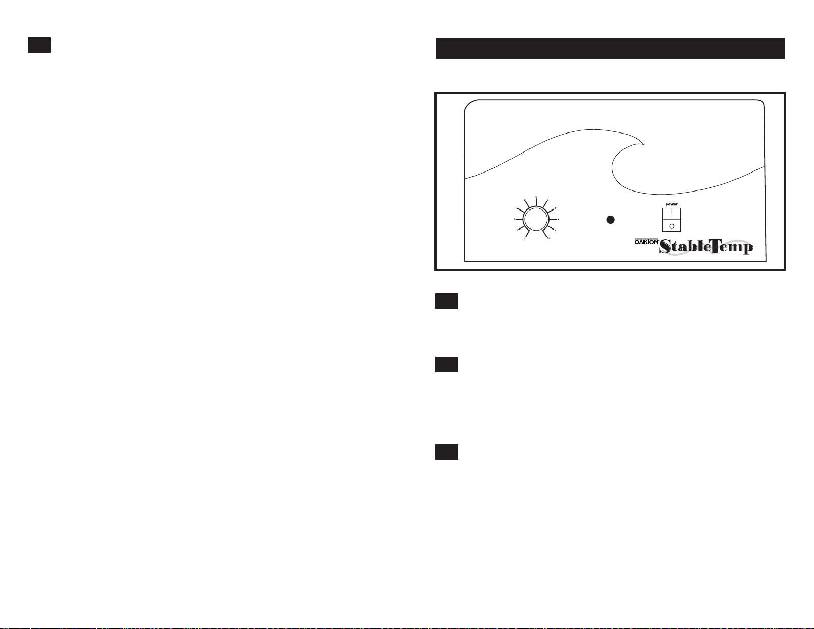
4.0 Control Panel Overview (Analog Models 12501-00 to 12500-35)
Power
The main power I/O (on/off) switch controls all power to the bath. It must be in the
I or ON position and illuminated before any systems are operational.
Temperature Controller
This control is marked Temperature. It controls your selection of water bath operat-
ing temperature on a scale of 0 to 10. This scale does not represent temperature, but
is to be used as a reference guide. The operating range is 5°C above ambient to
100°C.
Heating Indicator
This pilot lamp is marked Heating and is ON when the Main Temperature
Controller is energizing the heating element. The element will cycle on and off as
needed to maintain the set point temperature.
3.5
4.1
4.2
4.3
heating
temperature
Figure 1: Control panel, analog models 12500-00 to 12500-35
Page 5

9
8
5.0 Control Panel Overview (Digital Models 12501-00 to 12501-25)
Power Switch
The main power I/O (on/off) switch controls all power to the bath. It must be in the
I or ON position and illuminated before any systems are operational.
Main Temperature Controller
This controller is marked Temperature and consists of the digital display with
▲ / ▼ (Up/Down) key pads for inputting set point temperatures and calibration.
Heating Indicator
This pilot lamp is marked Heating and is ON when the Main Temperature
Controller is energizing the heating element. The element will cycle on and off as
needed to maintain the set point temperature.
Overtemperature Safety Control Thermostat
This is a hydraulic control with a remote sensor that is completely independent of
the Main Temperature Controller. It is mounted on the control panel and marked
Safety. The Safety Controller provides over-temperature protection in the unlikely
event the Main Temperature Controller fails, and the temperature should rise past
the set point. Temperature is then limited to the Safety set point.
5.1
5.2
5.3
5.4
Figure 2: Control panel, digital models 12501-00 to 12501-25
Safety Indicator
This pilot lamp marked Safety comes ON in the event that the operating temperature exceeds the Main Temperature Controller set point and reaches the Safety
Controller set point. Note: under normal operating conditions this indicator should
never be on.
5.5
Page 6

6. Operation
WARNING: THESE BATHS ARE NOT INTENDED FOR USE AS ACID BATHS.
USE AS AN ACID BATH WILL CAUSE SEVERE DAMAGE TO BATH COMPONENTS AND VOID YOUR WARRANTY. DO NOT USE DEIONIZED WATER,
TAP WATER, OR CHEMICALS. USE DISTILLED WATER ONLY.
Analog Models 12500-00 through 12500-35
6.1.1 Power Supply
Connect the service cord to the grounded outlet and push the power switch to the
ON position. If supplied with a detachable cordset, plug the female end into the
inlet of the unit and the male plug into the supply. Assure that units requiring a
fuse have a fuse installed. This fuse may be at the inlet part of the cordset male
plug.
6.1.2 Filling
Fill bath to your required depth with distilled water only. DO NOT USE tap water.
DO NOT USE deionized water. Note that normal depth is two-thirds full, but
depth must be at least 2 inches (5 cm).
6.1.3 Insert Thermometer:
Place thermometer in position as desired (a clip is provided with your accessory
package). See Figure 3.
10
11
6.1.4 Setting Temperature
To set the Temperature Control, turn the knob clockwise to the maximum setting.
The Heating light will glow indicating that the bath is heating. Allow the unit to
heat until the reference thermometer has reached the desired temperature. When
the desired temperature has been reached, turn the control knob counterclockwise
just until the Heating light goes off. Allow the unit to stabilize for several hours.
Re-adjust the control knob up or down as required until the desired temperature is
obtained. Allow the unit to stabilize between each setting. Temperature stability is
obtained when the Heating light is going on and off automatically and the temperature value in the bath remains constant.
Digital Models 12501-00 through 12501-25
6.2.1 Filling
Fill the bath to the desired level with distilled water. DO NOT USE TAP WATER
OR DEIONIZED WATER. The water depth must be at least 5 cm above the sensing
probe (which extends in to the tank) or unstable temperatures will occur.
6.2.2 Power Supply
Connect the service cord to the grounded outlet and push the power switch to the
ON position. If supplied with a detachable cordset, plug the female end into the
inlet of the unit and the male plug into the supply. Assure that units requiring a
fuse have a fuse installed. This fuse may be at the inlet part of the cordset male
plug.
6.2.3 Safety Control Thermostat
Turn the Safety Control clockwise to its maximum position. Acoin or flathead
screwdriver is necessary to turn the knob.
6.2.4 Setting Temperature Controller:
Enter desired set point temperature in °C. To enter set point mode on the Controller,
press either the ▲ or ▼ (Up or Down) button once. The digital display will start to
blink from bright to dim. While blinking, the digital display is showing the set
point. To change the set point, use the ▲ and ▼ buttons. If the buttons are not
pressed for five (5) seconds, the display will read the actual bath temperature. Allow
the bath at least two (2) hours to stabilize. NOTE: If operating the bath above 60°C
the bath cover must be used to obtain temperature desired.
6.1
6.2
Figure 3
Pinch clip to increase
friction and keep
thermometer from
sliding
Magnetic
Strip
This clip can be mounted
from any side of the bath
Thermometer bulb must not touch sides or bottom of the bath
but must be fully immersed. The location of the thermometer
may be determined by the opening in the bath cover if used.
Page 7

12 13
6.2.5 Calibrating Temperature Control
We recommend calibration of the bath once it is in its working environment and stabile at set point. Place a reference thermometer in the bath (there is a thermometer
clip provided with your accessories package). See Figure 3 on page 10.
Allow the thermometer to stabilize for at least one hour. Compare the reading on
the reference thermometer with the temperature control display. If there is a difference, put the display into calibrate mode by pressing both the ▲ or ▼ (Up or Down)
arrow pads simultaneously until the two (2) outside decimal points begin to blink.
When the display is blinking, press either the ▲ or ▼ arrow pads to adjust the display to match the reference thermometer. If the arrow pads are not pressed within
five (5) seconds the display will revert to the actual bath temperature. Allow the unit
to restabilize, and repeat above if necessary.
6.2.6 Setting Safety Control Thermostat
As mentioned in section 6.2.3, the Safety Thermostat should be initially set to its
maximum position to allow the water bath to stabilize. Once the bath maintains the
set point, turn the Safety Thermostat counterclockwise until the Safety Indicator
light turns on. Then turn the Safety Thermostat clockwise slowly, until the safety
indicator light turns off. This will set the Safety Thermostat at approximately 1°C
above the Temperature Control set point.
7.0 Maintenance
Note: Prior to any maintenance or service on this unit, disconnect service cord from
the electrical supply source.
Cleaning
Clean the stainless steel tank with a mild soap and water solution. Rinse with clean
water and wipe dry with soft cloth. Clean the outer surfaces with a damp sponge
and wipe dry avoiding the electrical controls. Foreign material may cause small rust
spots that show up in the bath. Remove these rust spots with a mild abrasive; never
use steel wool. Failure to periodically polish out these rust spots may cause premature failure of the bath tank.
Heating elements
The heating element of this bath does not contact the tank bottom, thus will not
burn out if the tank is allowed to run dry; however, a tank going dry may strain
interior surfaces so this should not be allowed to occur.
WARNING: IF TANK BOILS DRY WHILE CONTAINING PLASTICWARE,
THE PLASTIC WILL MELT. IF YOU INTEND TO USE TEST TUBE RACKS,
REMEMBER THAT PLASTIC COATED WIRE RACKS MAY WEAR AND
EXPOSE METAL WHICH CAN CAUSE DAMAGE. PREFERABLY, USE ALL
PLASTIC.
7.1
7.2
Page 8

14 15
Problem Solution
Temperature too high 1) Main controller set too high
2) Main controller failed on – call Customer Service.
3) Wiring error – call Customer Service.
Display reads "HI" or "400"+ Probe is unplugged, is broken or wire to sensor
is broken – call Customer Service
Temperature spikes over Recalibrate
set point and then settles
to set point
Temperature too low 1) Main controller set too low
2) Bath temperature not recovered from water
being added – wait for display to stop changing.
3) Unit not recovered from power failure or being
turned off – bath will need a minimum of
2 hours to warm up and stabilize.
4) Element failure; compare current draw to
data plate.
5) Main controller failure – confirm with front panel
lights that controller is calling for heat.
6) Wiring problem; check all functions and
compare wiring to wiring schematic
especially around any areas recently worked on.
7) Loose connection – call Customer Service.
Display reads "LO" 1) Sensor is plugged in backwards –
call Customer Service.
2) If ambient temperature is lower than range of unit
– compare set points and ambient temperature to
rated specifications in section 7.0,
Unit Specifications.
Unit will not heat over a 1) Confirm that amperage and voltage match data
temperature that is plate.
below set point 2) Confirm that set point is set high enough.
3) Check calibration – using independent
thermometer, follow instructions in section 4.5
Unit will not heat up at all 1) Check amperage – amperage should be virtually
at maximum rated (data plate) amperage.
2) Do all controller functions work?
3) Has the fuse/circuit breaker blown?
8.0 Troubleshooting
Temperature
8.1
Problem Solution
Indicated bath temperature 1) ±0.3 may be normal, especially without the use
unstable of bath cover.
2) Is ambient room temperature radically changing
– either door opening or room airflow from
heaters or air conditioning ? – stabilize
ambient conditions.
3) Calibration sensitivity – recalibrate.
Call customer service if re-calibration
does not resolve fluctuation.
4) Assure that the bath is at least one-third full.
5) Electrical noise – remove nearby sources of RFI
including motors, arcing relays or radio
transmitters.
6) Bad connection on temperature sensor or
faulty sensor – call Customer Service.
Will not maintain set point 1) Assure that set point is at least 5 degrees above
ambient room temperature.
2) See if ambient is fluctuating.
Display and Reference 1) Calibration error
thermometer don’t match 2) Temperature sensor failure; call Customer Service.
3) Controller failure – call Customer Service.
4) Allow at least two hours to stabilize.
5) Verify that reference thermometer is certified.
Can't adjust set points 1) Turn entire unit off and on to reset.
or calibration 2) If repeatedly happens, call Customer Service.
Calibrated at one This can be a normal condition when operating
temperature, but temperature varies widely. For maximum accuracy,
not at another calibration should be done as close to the set point
temperature as possible.
Page 9

16 17
9.0 Parts
Mechanical
8.2
Problem Solution
Water leaking 1) Dry bath and check the tank with flashlight to
see if leak is noticeable.
2) Fill tank again and see if leak repeats and find
source of leak. Call Customer Service if continues.
Holes or rust in 1) Assure that clean, distilled water is used –
water bath tanks deionized water, tap water and chemicals should
never be used in the tank. USE DISTILLED
WATER ONLY.
2) Assure that no test sample has leaked into
bath water.
3) No metallic products should be in the tank
with exception of the polymer coated rack.
Other
8.3
Problem Solution
Controller on at all times- 1) Turn unit off and on to reset.
"locked-up" 2) If cannot change any condition on the front panel,
call Customer Service.
Front panel displays Check for wire damage.
are all off
Unit or wall fuse/ 1) Check wall power source.
circuit breaker is blown 2) Compare current draw and compare to specs
on data plate.
3) See what other loads are on the wall circuit.
Unit will not turn on 1) Check wall power source.
2) Check fuse circuit breaker on unit or in wall.
3) Check all wiring connections,
esp. around the on/off switch.
Unit is smoking – This is not an uncommon occurrence for new units.
out of box The elements will burn off protective coatings.
Run the bath at high temperature for one hour
until smoke dissipates.
Description 120 VAC 220 VAC
EMI Filter N/A 2800502
Fuse, 6.3 Amp N/A 103555
Heating Element 2350503 120071
Pilot Lamp, Heating (green) 200021 200021
Pilot Lamp, Safety (red) 200020 200020
Power Cord 100014 104192
Power Switch 103351 103351
Safety Controller 100001 100001
Temperature Controller w / Probe 1750564 1750565
Gable for 5-L bath 12500-70
Gable for 12-L bath 12500-71
Gable for 20-L bath 12500-72
Mercury-filled Glass Thermometer 01252-05
Spirit-filled Glass Thermometer 93905-91
Page 10

18 19
10.0 Specifications 11.0 Wiring Diagrams
12500-00, -05 12500-10, -15 12500-20, -25 12500-30, -35
Capacity 2.25 L (0.59 gal) 5 L (1.32 gal) 12 L (3.17 gal) 20 L (5.28 gal)
Temperature Range 5° above ambient to 100°C (212°F)
Temperature Control On/off hydraulic thermostat
Stability ±0.3°C at 37°C
5.75" x 5.5" 11.5" x 5.875" 11.5" x 12.75" 11.5" x 19.5"
Bath (W x H x D) x 6" (14.6 x x 6" (29.2 x x 6" (29.2 x x 6" (29.2 x
14.0 x 15.2 cm) 14.9 x 15.2 cm) 32.4 x 15.2 cm) 49.5 x 15.2 cm)
8.25" x 7.25" 14" x 9.5" 14" x 9.5" 14.75" x 9.5"
Overall (W x H x D) x 10.75" (20.9 x x 12" (35.6 x x 18.75" (35.6 x x 24.5" (37.5 x
18.4 x 27.3 cm) 24.1 x 30.5 cm) 24.1 x 47.6 cm) 24.1 x 62.2 cm)
Shipping weight 16 lbs (7.3 kg) 23 lbs (10.5 kg) 31 lbs (14.1 kg) 37 lbs (16.8 kg)
These units are 100V or 220V. Please refer to the unit data plate for its individual
specifications.
12500-00 THROUGH 12500-35
CE approved units only
inlet
Filter
Fuse
Plug Styles
NEMA 5-15P NEMA 6-15P EUI-16P UK-13P
On/Off switch
Regulating Thermostat
Heating Element
Lights while heating pilot
Power on pilot
Analog Models
12501-00, -05 12501-10, -15 12501-20, -25
Capacity 5 L (1.32 gal) 12 L (3.17 gal) 20 L (5.28 gal)
Temperature Range 5° above ambient to 100°C (212°F)
Temperature Control PID microprocessor, RTD
Stability ±0.20°C at 37°C
11.5" x 5.875" x 6" 11.5" x 12.75" x 6" 11.5" x 19.5" x 6"
Bath (W x H x D)
(29.2 x 14.9 x 15.2 cm) (29.2 x 32.4 x 15.2 cm) (29.2 x 49.5 x 15.2 cm)
14" x 9.5" x 12" 14" x 9.5" x 18.75" 14.75" x 9.5" x 24.5"
Overall (W x H x D)
(35.6 x 24.1 x 30.5 cm) (35.6 x 24.1 x 47.6 cm) (37.5 x 24.1 x 62.2 cm)
Shipping weight 23 lbs (10.5 kg) 31 lbs (14.1 kg) 37 lbs (16.8 kg)
Digital Models
Page 11

20 21
12501-00 THROUGH 12501-25
CE models
Use cord adapter plate with bushing
hole for domestic models
Fuse on domestic models may be
required or second fuse on DIN models
IEC 320
Inlet with
fuse
EMI Filter
Plug Styles
NEMA 5-15P NEMA 6-15P EUI-16P UK-13P
Power on pilot
Sensing Probe
Temperature Control
Safety pilot
Heat on Pilot
Safety Control
Load
Ground
Neutral
Hot
Sensing Probe
Temperature Control
Safety pilot
Heat on Pilot
Safety Control
Load
Ground
Neutral
Hot
Note: this duplicate circuit for Model 1255 only
Page 12

22 23
 Loading...