

Page 1

OPERATING MANUAL
ROTO-TORQUE®HEAVY DUTY ROTATORS
MODEL NOS. 07637-00 AND 07637-10
Cole-Parmer Instrument Company
625 East Bunker Court
Vernon Hills, Illinois U.S.A. 60061-1844
(847) 549-7600
(847) 247-2929 (Fax)
800-323-4340
www.coleparmer.com
e-mail: techinfo@coleparmer.com
A-1299-0029
Edition 09
SUPPLIER CERTIFIED
Page 2

DESCRIPTION
The COLE-PARMER ROTO-TORQUE Rotator consists of two units; the rotator assembly and the
Multipurpose disc. The rotator assembly is available in two models, wired for 115V AC 50/60 Hz (No.
07637-00) or 230V AC 50/60 Hz (No. 07637-10) input power. The rotator assembly contains a motor ,
speed control circuit, housing, base bracket and the rotor shaft adapter. The Multipurpose disc (No.
07637-01) includes small clips, large clips and mounting hardware.
The ROTO-TORQUE Rotator combines functional features with its attractive packaging. It can be
used for very low to moderate agitation. It has a stepless electronic speed control which can vary
the speed from about 3 to 80 rpm. Even with heavier loads on and around the rotating disc, the disc
will have a smooth rotation without cogging. The unit has an adjustable tilt housing that can be set
by an operator to the correct angle desired for a particular test.
The Multipurpose disc can accept different sizes of clips. They can hold test tubes, flasks and bottles. Clips around the periphery of the disc are placed at an angle. Any test tube placed in this clip
will move through a figure 8 motion causing a sloshing effect and mixing of its contents.
The unit is designed such that in most cases (when the disc is not heavily loaded), the center of
gravity of the system will act to tilt the disc upward. This safety device is provided in case the side
knob is left loose by mistake.
Trademarks bearing the ® symbol in this publication
are registered in the U.S. and in other countries.
Page 2
Page 3
ASSEMBLY AND GENERAL INFORMATION
Install the housing assembly on the base bracket using the top two slots in the sides of the base
bracket. It may be necessary to pull the sides of the base bracket outward for this installation.
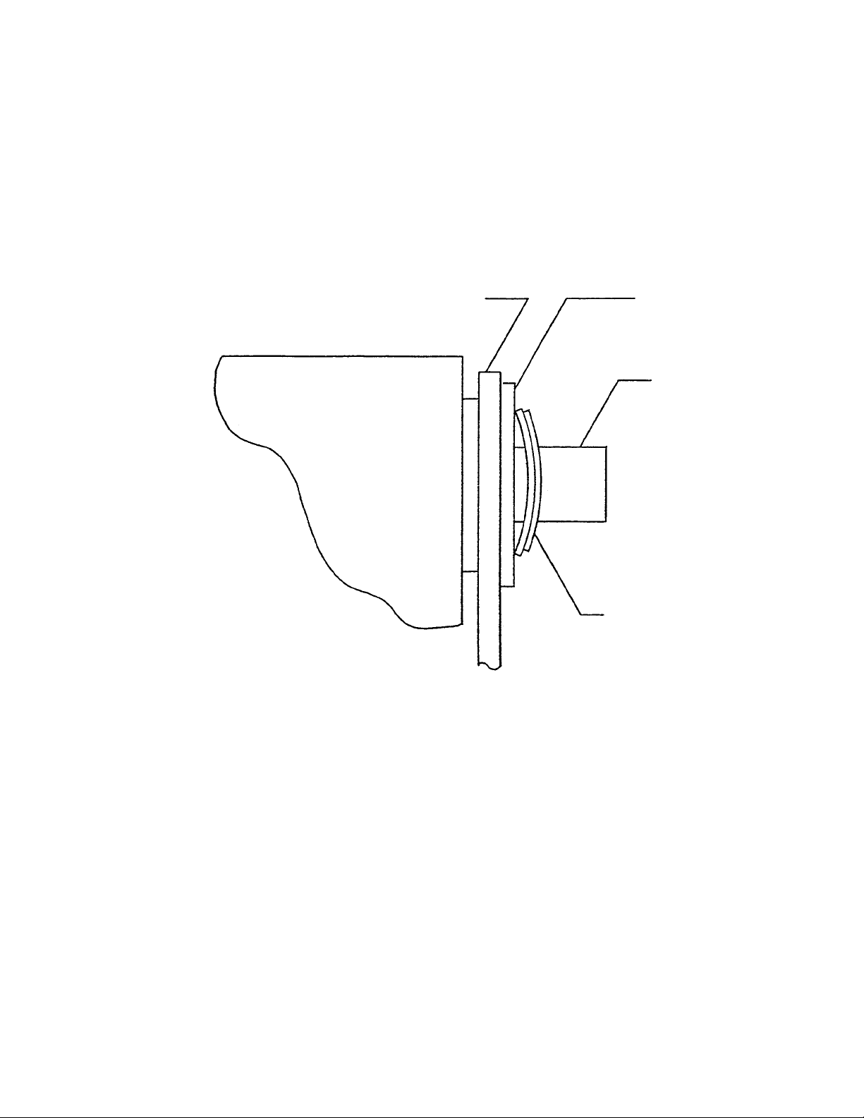
Place the fiber washer and two curved washers on the threaded shaft (side-axle) as shown in the
sketch. Use the side knob on the threaded shaft (axle) (it is the largest of the two knobs). Determine
the required tilt of the housing and tighten the side knob. The tilt angle of the housing can be
changed by loosening the side knob.
Slide the rotor shaft adapter onto the motor shaft. Tighten the set screws using the Allen wrench supplied with the unit. Line up the roll pin of the shaft adapter with the corresponding hole in the disc.
Attach the disc by tightening the adapter knob.
Two sizes of clips are supplied with the disc. They can grip diameters of 10 to 20 mm. The clamping diameters can be varied somewhat by slightly bending the clips. An extra large clip (20-25 mm)
and giant (25-40 mm) clip is also available as an accessory.
The clips can be attached on the periphery or the flat surface of the disc. Thirty mounting holes on
the periphery and sixteen holes on the front of the disc are provided for mounting the clips.
Page 3
BRACKET
CABINET
HOUSING
CURVED WASHERS
THREADED
SHAFT
FIBER
WASHER
Page 4

DIFFERENT APPLICATIONS
The Rotator can be used for:
Micro-Diffusion determinations
Semi-Micro extractions
Washing precipitates
Blood reconstruction
Dissolving of separations from Chromatography paper
Gas saturation of blood
Moderate agitation in tubes, flasks and bottles
OPERATING CHARACTERISTICS
The unit is equipped with a 6-foot three wire line cord and three prong plug. The third grounded wire
is connected to the chassis of the housing. Maximum current requirement is 0.3A at 115V AC for
Model 07637-00 and 0.15A at 230V AC for Model 07637-10. The units will work on 50-60 cycles.
Depending upon the position of the range switch, high or low speed range settings will be available
on the speed control reference dial. The low range is about 3 to 18 rpm. The high range is about 16
to 80 rpm. The high-low range switch has a center “off” position. This “off” position can be used to
turn the unit on and off without disturbing the speed setting.
The Rotator provides high torque even at low speeds. Yet, it is recommended that for best results,
balance the load as much as possible on the periphery of the disc.
The dial graduations on the speed control are for reference only; they are not calibrated as to rpm.
The 07637-10 model uses the same circuit and motor as the 07637-00 with the addition of a step
down autotransformer to reduce the 230V input to 115V. The on-off switch is in the 115V secondary.
With the switch off, some current still passes through the primary. Unplug the 07637-10 from the AC
receptacle when not in use.
Note
COLE-PARMER INSTRUMENT COMPANY reserves the right to make improvements in design,
construction and appearance of our products without notice.
Page 4
Page 5

W ARRANTY
The Manufacturer warrants this product to be free from significant deviations from published specifications. If repair or adjustment is necessary within the warranty period, the problem will be corrected at no charge if it is not due to misuse or abuse on your part as determined by the
Manufacturer. Repair costs outside the warranty period, or those resulting from product misuse or
abuse, may be invoiced to you.
The warranty period for this product is noted on the Warranty Card.
PRODUCT RETURN
To limit charges and delays, contact the seller or Manufacturer for authorization and shipping instructions before returning the product, either within or outside of the warranty period. When returning the
product, please state the reason for the return. For your protection, pack the product carefully and
insure it against possible damage or loss. Any damages resulting from improper packaging are your
responsibility.
TECHNICAL ASSISTANCE
If you have any questions about the use of this product, contact the Manufacturer or authorized
seller.
Page 6
Page 6

REPLACEMENT PARTS LIST
Part Description Part No.
Gearmotor B-1952
Speed Control B-1496-2
Switch-Toggle B-1084-16
Side Knob B-1083-19
Adapter Knob B-1083-18
Small Knob B-1083-3
Bracket Assembly B-1786-1CR
Adapter Assembly A-1 141
Rubber Foot A-1390-1
Small Clip (10-15 mm) 07637-40
Large Clip (15-20 mm) 07637-50
Package of 50 screws and washers B-1238-31
for the clips
ACCESSORIES
Extra Large Clip (20-25 mm) 07637-60
Giant Clip (25-40 mm) 07637-70
Multipurpose Disc 07637-01
Test Tube Basket 07637-05
Serum Bottle Disc 07637-75
Page 5
Page 7

Page 7
07637-00
INPUT POWER
APPLIED AT B & D
07637-10
T1 IS ADDED:
INPUT POWER
APPLIED AT E & F
A & B AND C & D
ARE CONNECTED
ROTATOR SCHEMATIC
230V AC
115V AC
LAMP
HIGH
OFF
LOW
B-1496-2
R1
D3
D2
D1
Q1
F
C
R2
R3
R4
C1
C2
B
A
E
M
D4
D
T1
T2
Printed in U.S.A.
090700
 Loading...