

Page 1
1
0
3
2
4
5
6
7
8
9
10
Set Temperature
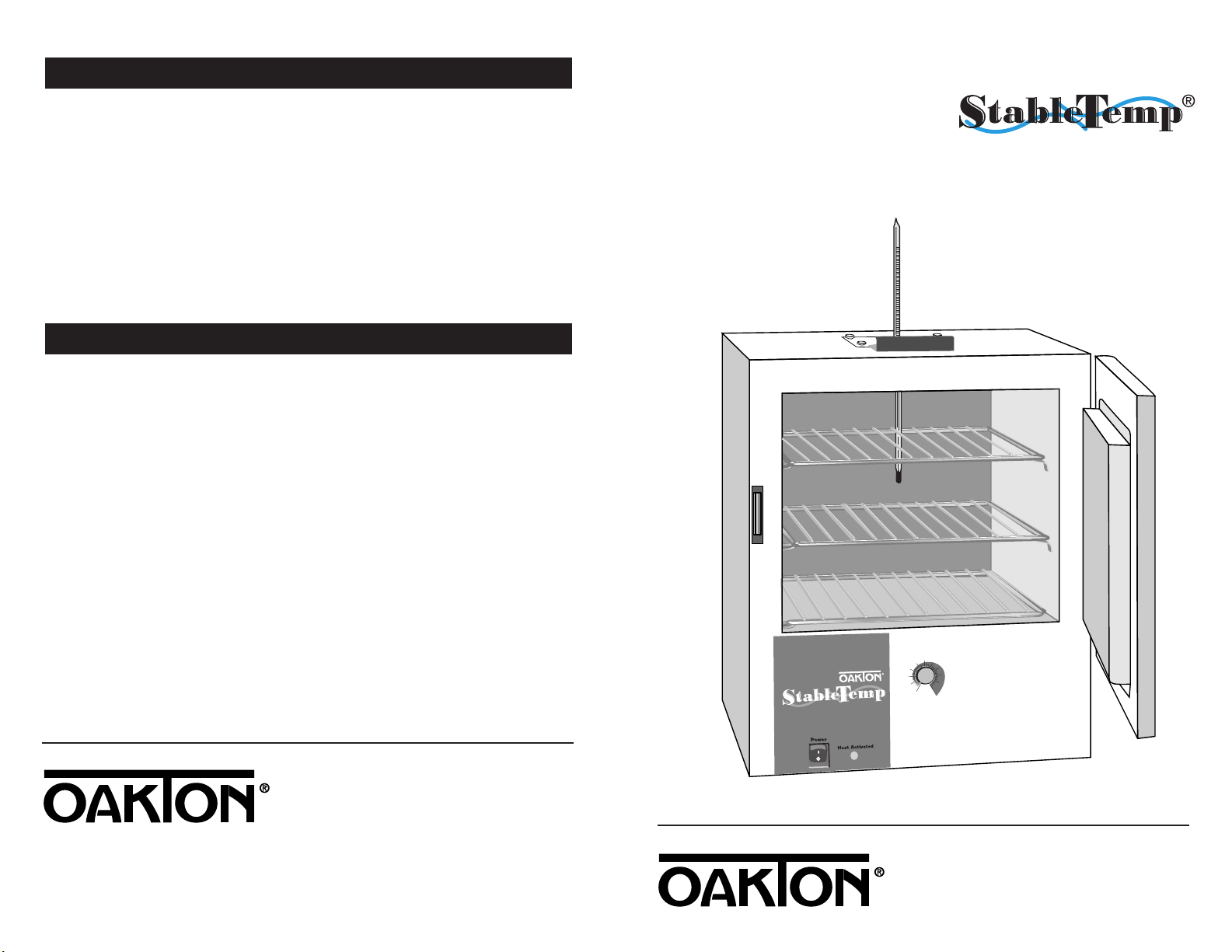
OPERATING INSTRUCTIONS
Economy Ovens
Printed in the U.S.A. 5/01
www.4oakton.com
000-00
12. Warranty
OAKTON warrants this oven to be free from significant deviations in material
and workmanship for a period of one year from date of purchase. If repair or
adjustment is necessary and has not been the result of abuse or misuse within
the warrantied time period, please return—freight prepaid—and correction will
be made without charge. OAKTON alone will determine if the product problem
is due to deviations or customer misuse.
Out-of-warranty products will be repaired on a charge basis.
13. Return of items
Authorization must be obtained from our Customer Service Department before
returning items for any reason. When applying for authorization, please include
data regarding the reason the items are to be returned. For your protection, items
must be carefully packed to prevent damage in shipment and insured against possible damage or loss. We will not be responsible for damage resulting from careless or
insufficient packing. Arestocking charge will be made on all unauthorized returns.
NOTE: We reserve the right to make improvements in design, construction, and
appearance of products without notice.
05015-41, -45, -51, -53, -59, -61
Page 2

Table of Contents
1.0 Introduction.....................................................................................................................4
2.0 Receiving and Inspection .............................................................................................4
2.1 Inspection .......................................................................................................................4
2.2 Accessories .....................................................................................................................4
3.0 Installation ...................................................................................................................5-6
3.1 Power Source.................................................................................................................5
3.2 Location ..........................................................................................................................5
3.3 Lifting / Handling........................................................................................................5
3.4 Leveling..........................................................................................................................5
3.5 Cleaning .........................................................................................................................6
4.0 Control Panel Overview ...............................................................................................7
4.1 Power ..............................................................................................................................7
4.2 Temperature Controller ................................................................................................7
4.3 Heating Light .................................................................................................................7
5.0 Precautions.......................................................................................................................8
6.0 Operation..........................................................................................................................9
6.1 Power Supply ................................................................................................................9
6.2 Setting Main Temperature ...........................................................................................9
7.0 Maintenance...................................................................................................................10
7.1 Cleaning........................................................................................................................10
7.2 Storage ..........................................................................................................................10
8.0 Troubleshooting.......................................................................................................11-13
8.1 Temperature............................................................................................................11-12
8.2 Mechanical ...................................................................................................................13
8.3 Other .............................................................................................................................13
9.0 Parts / Accessories ........................................................................................................14
10.0 Specifications..............................................................................................................15
11.0 Wiring Diagram....................................................................................................19-20
12.0 Warranty.......................................................................................................................24
13.0 Return of Items...........................................................................................................24
2 3
Page 3

5
3. Installation
Local city, county or other ordinances may govern the use of this equipment. If you
have any questions about local requirements, please contact the appropriate local
agency. Installation may be performed by the end user. It is unnecessary for this unit
to be installed by a technician.
Under normal circumstances this unit is intended for use inside, at room temperatures between 5°C and 40°C, at no greater than 80% relative humidity (at 25°C) and
with a supply voltage that does not vary by more than 10%. Customer Service
should be contacted for operating conditions outside of these limits.
Power Source
The electrical supply to the unit must conform to all national and local electrical
codes. The power source must match the voltage, cycle, phase and ampere requirements listed on the data plate (located just above the power cord on the back side of
the oven) This unit is intended for 50/60 HZ application. Make sure your power
supply matches that shown on the data plate. The voltage of the outlet should not
vary more than 10% from the dataplate rating. A separate circuit is recommended
to preclude loss of product due to overloading or circuit failure.
Location
When selecting a site for the oven, consider conditions that may effect performance,
such as heat or cold from air vents, fast moving air currents, other ovens, autoclaves,
direct sun, etc. Avoid high traffic areas that may reduce accessibility to the oven and
allow at least 5 cm between the unit and surrounding walls or partitions that might
obstruct free airflow.
Lifting / Handling
These units are heavy and care should be taken to use appropriate lifting devices
that are sufficiently rated for these loads. Units should only be lifted from their bottom surfaces. Doors, handles, and knobs are not adequate for lifting or stabilization.
The unit should be completely restrained from tipping during lifting and transport.
All moving parts, such as shelves and trays should be removed and doors need to be
positively locked in the closed position during transfer to prevent shifting and damage.
Leveling
The unit must sit level and solidly. The oven is equipped with non-adjustable rubber feet to raise it off the counter and prevent sliding; however, the counter must be
level to provide optimum working and safety conditions.
4
1. Introduction
Thank you for purchasing an OAKTON®StableTemp®Economy Oven! These units
are general purpose gravity convection ovens for professional, industrial or educational use where the preparation or testing of materials is done at approximately
atmospheric pressure and no flammable, volatile, or combustible materials are being
heated. These units are not intended for hazardous or household use.
Your satisfaction and safety require a complete understanding of this unit. Read the
instructions thoroughly and be sure all operators are given adequate training before
attempting to put the unit in use. Note that this equipment must be used only for its
intended application; any alterations or modifications will void your warranty.
See back page of this manual for more warranty information.
2. Receiving and Inspection
Inspection
The carrier accepts responsibility for safe delivery and is liable for loss or damage.
On delivery, inspect for visible exterior damage. Describe and note on the freight bill
any damage found on the shipping carton or unit and enter a claim on the form supplied by the carrier.
Inspect for concealed loss or damage on the unit itself. If any damage is found the
carrier will arrange for an official inspection to substantiate your claim.
If for any reason you must return the unit, authorization must be obtained from our
Customer Service Department. See the back page of this manual for more information on return of items.
Accessories
Verify that all of the equipment indicated on the packaging slip is included with the
unit. Carefully check all packaging before discarding. Each unit is equipped with 2
adjustable shelves, 8 shelf clips, a spirit-filled glass thermometer, and a 6-ft, threewire line cord. The 120 VAC models also include a plug.
2.1
3.1
3.2
3.3
3.4
2.2
Page 4

6
Cleaning
The oven was cleaned at the factory, but not sterilized. Remove all interior parts,
including shelves and shelf clips if assembled and clean the inside of the chamber
thoroughly with a disinfectant that is appropriate for your application. DO NOT
USE chlorine-based bleaches or abrasive cleaners, as they will damage the ovens
interior surfaces. DO NOT USE spray cleaners that might leak through openings
and cracks and get on electrical parts or that may contain solvents that will harm
coatings. A regular periodic cleaning is recommended.
WARNING: Never clean the unit with alcohol or flammable cleaners with the unit
connected to the electrical supply. Always disconnect the unit from the electrical
service when cleaning and assure all volatile or flammable cleaners are evaporated
and dry before reattaching the unit to the power supply.
Shelves
Place shelves in the chamber at desired position. See Figure 1.
7
4.0 Control Panel Overview
Power
The main power I/O (on/off) switch controls all power to the oven. It must be in
the I, or ON position, and illuminated before any systems are operational.
Temperature Controller
Marked Set Temperature, this control is equipped with an adjustment knob and a
graduated dial. The graduated dial is marked with 10 major increments and 50
minor increments. The increments can be used as index points for setting and
returning to set point temperatures.
Heating Lamp
A green pilot light marked Heat Activated illuminates when the heating element has
been activated and is heating. When set point is reached the pilot light will cycle on
and off as the elements maintain the set temperature.
3.5
3.6
4.1
4.2
4.3
Figure 1:
Set Temperature
Power
Heat Activated
1
0
3
2
4
5
6
7
8
9
10
Figure 2: Control Panel
Squeeze clip and insert
into slots. Clip will have
to be tipped into the
top slot and then rolled
into the bottom slot
Clip/Shelf interface (4) clips per shelf.
Install clips at same elevation for each clip
Shelf location where desired.
(2) provided.
Page 5

9
8
5.0 Precautions
This unit has been designed with a dampered vent from the chamber. In order to
work effectively and safely, some precautions will need to be taken by the operator.
• In most applications, the exhaust damper will need to be open during drying or
degassing for best results.
• This oven is not an explosion proof oven and is not designed to handle combustible gasses. Do not place explosive, combustible or flammable materials into
the chamber.
• Some of the out-gassed byproducts may be hazardous or unpleasant to operating
personnel. If this is the case, the exhausts should be positively ventilated to the
outside and dealt with according to local regulations. Your dealer can provide
you with a power exhaust that greatly helps under these applications.
• Do not place sealed or filled containers in the oven chamber.
• This oven is NOT designed for use in Class I, II, or III locations as defined by the
National Electrical Code.
• This oven is not intended, nor can it be used, as a patient connected device.
Figure 3: Placement of new thermometer clip
6.0 Operation
Power Supply
The power supply must be properly grounded (earthed) and correctly sized to
match the unit data plate rating. The supply voltage must match the data plate
voltage within 10%. If supplied with a detachable cord set, plug the female end
into the inlet on the unit and the male plug into the supply. Assure that units
requiring a fuse have a fuse installed.
Push the power switch to the ON position and turn the Over Temperature
Thermostat to its maximum position, clockwise so it will not interrupt the setting of
the Main Temperature control.
6.1
Setting Main Temperature
Place the reference thermometer through the exhaust port on top of the unit; a clip is
provided with your accessory package. See Figure 3.
The operating range for this oven is ambient room temperature + 5°C to 200°C. To
set the Main Temperature Controller turn the knob to the desired oven temperature,
using the graduated dial as a reference guide. Allow one hour for the temperature
to stabilize. Using the reference thermometer, verify the oven temperature; if it is
not at the desired value, turn the control knob up or down as needed. Allow the
temperature to re-stabilize, continuing the process until the exact desired temperature is achieved.
Note: Slight vapor or smoke may occur in the initial heat-up. This is a normal occurrence when the oven is first brought up to temperature and protective coatings on
the element become hot.
6.2
This section clamped under the top plate
Pinch these points after installation to
create friction pressure on thermometer
clip installed
Loosen screws, slide clip
between top cover and body
where shown and retighten
scews
Note: use caution when closing damper
to avoid breaking thermometer
This section clamped under
the top plate
Page 6

10
11
7.0 Maintenance
Note: Prior to any maintenance or service on this unit, disconnect service cord from
the electrical supply source.
Cleaning
Clean the oven interior on a regular basis. When washing interior of unit, handle
gasket carefully so as not to impair the positive seal. Clean the inside of the chamber thoroughly with a disinfectant that is appropriate for your application. Make
sure to rinse the cleaned surface with a damp cloth. DO NOT USE chlorine-based
bleaches or abrasive cleaners, as they will damage the oven chamber. DO NOT USE
spray cleaners that might leak through openings and cracks and get on electrical
parts or that may contain solvents that will harm coatings.
WARNING: Never clean the unit with alcohol or flammable cleaners with the
unit connected to the electrical supply. Always disconnect the unit from the electri-
cal service when cleaning and assure all volatile or flammable cleaners are evaporated and dry before reattaching the unit to the power supply.
Storage
If the unit is to be shut down for an extended period of time, wipe the chamber
clean and let dry before closing door to eliminate possibility of contamination. If the
unit is to be transported, remove shelving and trays, clasp the door shut and disconnect the power supply. Please refer to Section 3.3, Lifting / Handling for further
direction.
No maintenance is required on the electrical components. If oven fails to operate as
specified please review Section 8.0, Troubleshooting, prior to calling customer
service.
7.1
7.2
Problem Solution
Temperature too high 1) Controller set too high
2) Controller failed on – call Customer Service.
3) Wiring error – call Customer Service.
Chamber temp spikes over Recalibrate
set point and then settles
to set point
Temperature too low 1) Thermostat set too low
2) Controller set too low
3) Unit not recovered from door opening – wait
for heating indicator to turn off
4) Unit not recovered from power failure or being
turned off – oven will need 1 hour to warm
up and stabilize
5) Element failure – see if heating indicator is on;
compare current draw to data plate
6) Controller failure – confirm with front panel light
that controller is calling for heat
7) Thermostat failure – confirm with front panel
light that it is operating correctly
8) Wiring problem – check all functions and
compare wiring to schematic in section 11.0 especially around any areas recently worked on
9) Loose connection – call customer service
Unit will not heat over 1) Confirm that amperage and voltage match
a temperature that is data plate.
below set point 2) Confirm that set point is set high enough–turn
Thermostat all the way clockwise and see if
heating light or safety light comes on
3) Check connections to sensor
4) Check calibration – using independent
thermometer, follow instructions in section 6.2
8.0 Troubleshooting
Temperature
8.1
Page 7

12 13
Problem Solution
Unit will not heat up at all 1) Verify that controller is asking for heat by looking
for heating indicator light – if pilot light is not
on continuously at initial start up, there is a
problem with the controller
2) Check amperage – amperage should be virtually
at maximum rated (data plate) amperage
3) Is the Thermostat set high enough? – for
diagnostics, should be fully clockwise with the
pilot light never on
4) Has the fuse/circuit breaker blown?
Chamber temperature 1) Is ambient room temperature radically changing
unstable; will not maintain – either door opening or room airflow from
set point heaters or air conditioning ? – stabilize
ambient conditions.
2) It may happen if exhaust stack is 100% open –
close exhaust stack.
3) Calibration sensitivity – call Customer Service
4) Thermostat set too low – be sure that it is more
than five degrees over desired set point; check
if pilot is on continuously; turn controller knob
completely clockwise to see if problem solved
then follow instructions in section 6.2 for
correct setting.
5) Assure that set point is at least 5 degrees over
ambient room temperature.
6) See if ambient is fluctuating
7) Verify that reference thermometer is certified.
Mechanical
8.2
Problem Solution
Door not sealing 1) Confirm that the door gasket is clean of debris
and aligned properly.
2) Confirm that unit has not been damaged and
that the body is square.
Other
8.3
Problem Solution
Unit or wall fuse/ 1) Check wall power source.
circuit breaker is blown 2) Compare current draw and compare to specs
on data plate.
3) See what other loads are on the wall circuit.
Unit will not turn on 1) Check wall power source.
2) Check fuse circuit breaker on unit or in wall.
3) Check all wiring connections,
esp. around the on/off switch.
Unit is smoking – Put unit under vent and run at full power for
out of box one hour
Contamination 1) See Cleaning procedure, section 3.5
in chamber 2) Develop and follow a standard operating
procedure for specific application; include
definition of cleaning technique and
maintenance schedule
Page 8

Model 05015-51, 53 05015-41, 45 05015-59, 61
Construction carbon steel interior, heavy-gauge welded steel
exterior and power-coat paint finish
Capacity 0.7 cu ft 1.3 cu ft 2.0 cu ft
Temperature Range 40 to 200°C (104 to 392°F)
Uniformity ±10°C
Chamber 12" x 10" x 10" 13" x 13" x 13" 17" x 17" x 12"
(W x H x L) 30.5 x 25.4 33.0 x 33.0 43.2 x 43.2
x 25.4 cm x 33.0 cm x 30.5 cm
Overall 17" x 17" x 20"/ 17" x 24" x 18"/ 22" x 22" x 27"/
(W x H x L) 43.2 x 43.2 43.2 x 60.9 55.8 x 55.8
x 50.8 cm x 45.7 cm x 68.5 cm
Shipping weight 39 lbs/17.7 kg 57 lbs/25.8 kg 39 lbs/17.7 kg
14 15
9.0 Parts & Accessories
Description 120VAC 220VAC
Cord Set 100014 101990
Knob Temperature Control 103519
Pilot Light Green 200021
On/Off Switch 103351
Heating Element 05015-51, 53 9570790 9570791
Heating Element 05015-41, 45 call call
Heating Element 05015-59, 61 9570792 9570793
Shelf for 05015-51, 53 05015-96
Shelf for 05015-41, 45 05015-97
Shelf for 05015-59, 61 05015-98
Shelf Clip 200116
Glass Thermometer 93905-93
10.0 Specifications
11.0 Wiring Diagrams
Domestic Styles
Plug Styles
NEMA 5-15P
NEMA 6-15P
On/Off switch
Main Temperature Control
Heat on Pilot
Heating Element
 Loading...