

COLENTA PrintlineProcessor 56 RA, PrintlineProcessor 66 RA, PrintlineProcessor 80 RA Instruction Manual
Page 1
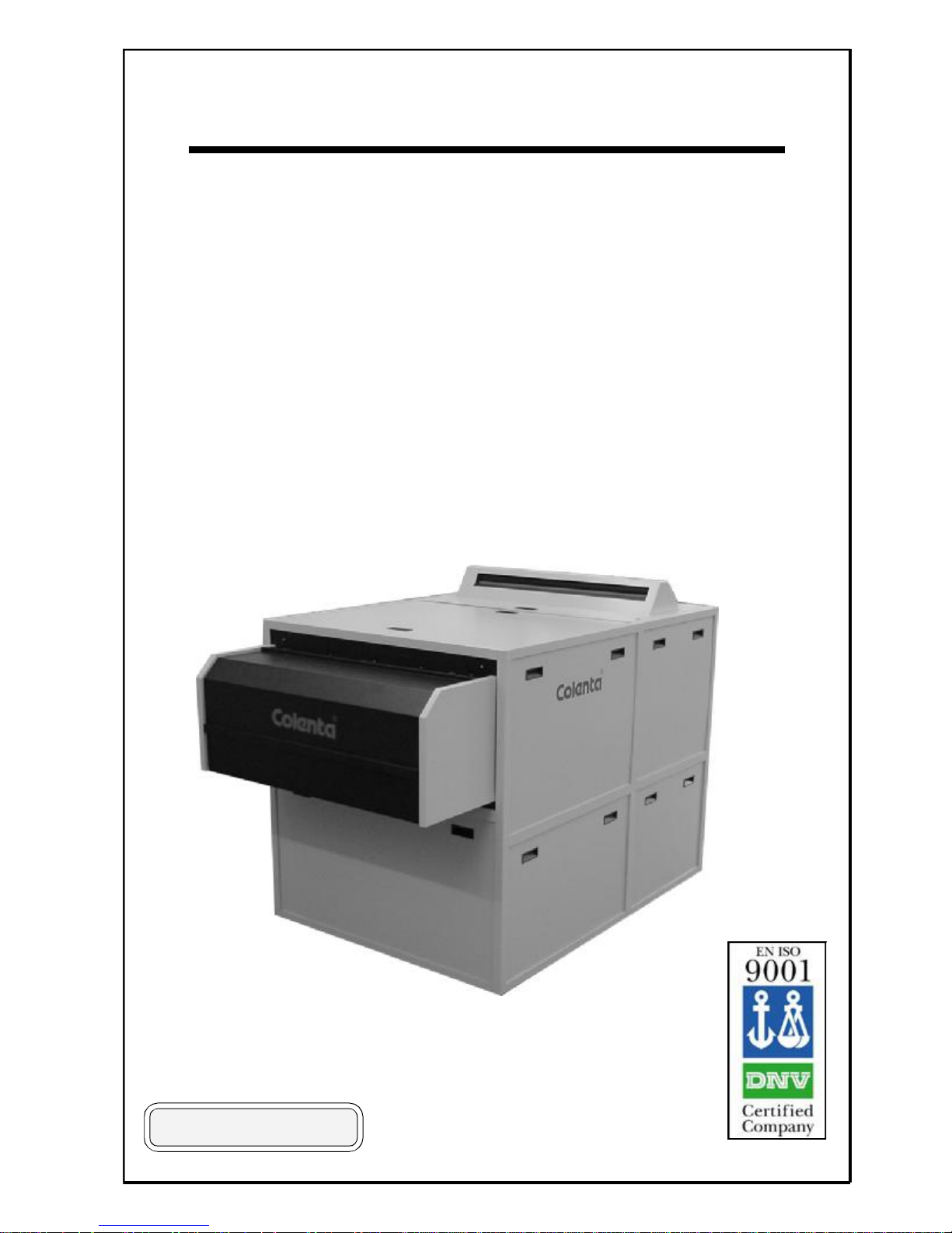
Instruction Manual
for COLENTA
PrintlineProcessor
56/66/80 RA
MP700 V5.2r04/05/06
06/2003 AN
Page 2

PrintlineProcessor
56/66/80 RA 70/95/120 - 5T
Technical Specifications:
Processing applications: RA Photopaper for digital applications incl. Duratrans
Paper width: max. 80 cm (31 inch)
Microprocessor Control: - with 9 preprogrammable processing cycles
Transport Speed (at 45 sec DEV-Time): - 70 cm/min (42 inch/min)
- 95 cm/min (42 inch/min)
- 120 cm/min (42 inch/min)
(preprogrammable 20 to 116 sec.)
Tankcapacity Temperature* Repl. Rate*
Developer : x lt 18 - 43°C 40-2000ml/m²
Bleachfix : x lt 18 - 43°C 40-2000ml/m²
Superstabi1 : x lt 18 - 43°C 40-2000ml/m²
Superstabi2 : x lt 18 - 43°C 40-2000ml/m²
Superstabi3 : x lt 18 - 43°C 40-2000ml/m²
Replenishment: - controlled by up to 10-sensors, measuring media area
- activated after 0,1 - 0,999m² *material fed into the processor
- antioxidation/standby replenishment, activated after 0-9 hours *
Anticrystalisation/
Selfcleaning Cycle
during Standby: - activated : each 1 - 20 min *
- cycle time : duration 1 - 3 min *
Filter Replacement Programming: 0 - 9999 m² *
.........* all values preprogrammable
Control: - Activate and Monitoring features inform, warn and alert the operator to an error in the system.
Solution Levels: -Low Level monitoring in Dev-, Bleachfix, and all Superstabi- Tanks
of processor **
-High Level monitoring in Overflow Collection Tanks (waste management) **
-Low Level in Repl. Tanks for Dev-, Bleachfix and Superstabi **
Temperatures: High / Low level monitoring of the Dev, Bleachfix, Superstabi and Dryer
Work in Progress : Details the position of the media through the processor.
Transport: - drive motor overload monitoring **
- security cover lid switch **
- manual feed facility
** when activated will operate an audible warning and a message alert to confirm the error type.
Additional Accessories and Features:
- Chiller unit (optional)
- A drawer unit within the main frame to house the replenishment and waste collection tanks.
Technical specification subject to change without notice.
Page 3
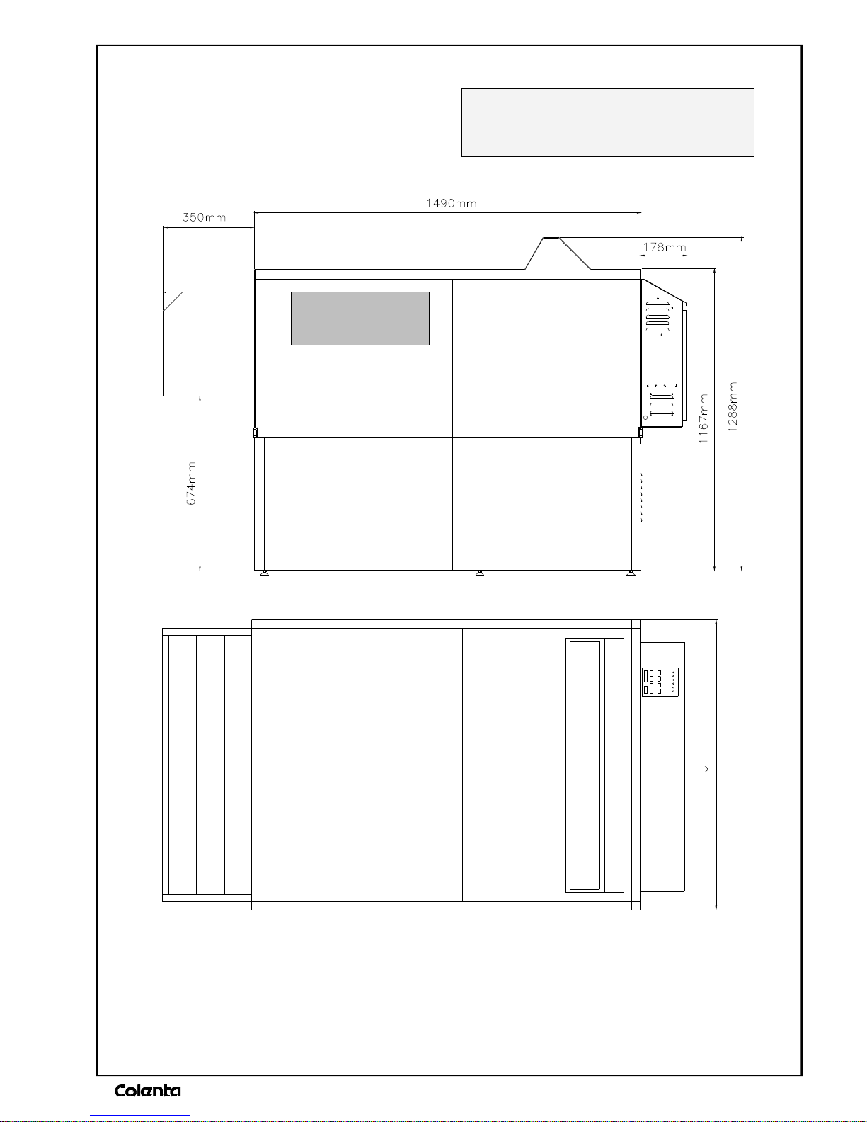
DIMENSIONS:
COLENTA 56/66/80 RA-xx 5T
RA xx 5T SST
Y for RA 56 860 mm
Y for RA 66 960 mm
Y for RA 80 1100 mm
Page 4

INDEX
1. INTRODUCTION / SAFETY INSTRUCTIONS 1-6
2. BEFORE INSTALLATION 7
3. TRANSPORT AND ASSEMBLY 8 - 10
4. PROCESSOR FUNCTIONS 11
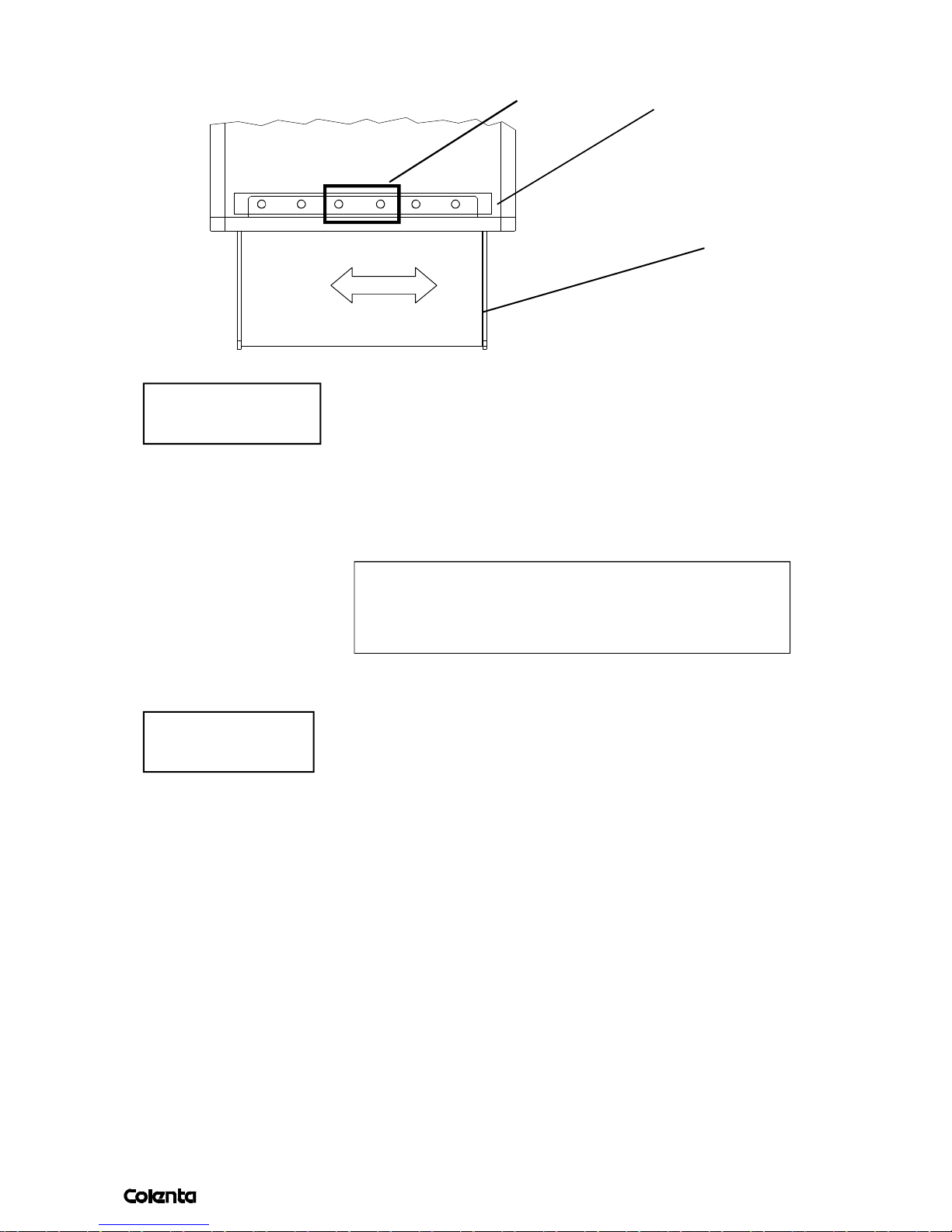
5. INFRARED SENSORBAR 12
6. REPLENISHMENT SYSTEM 13,14
7. HEATING / COOLING / CIRCULATION 15-17
8. TEST RUN AND TANK FILL 18
9. WORKING WITH THE CHEMISTRY 18
10. WORKING WITH THE PROCESSOR 19
11. CONTROL PANEL 20-31
12. MAINTENANCE 32
13. RECOMENDED MAINTENENCE EVERY 3-6 MONTH 33
14. SAFETYINSTRUCTIONS 34,35
Page 5
AN 06/2003
page
1
1.INTRODUCTION
Congratulations upon your decision to buy a
COLENTA RA-Processor.
Your purchase has been designed to meet the highest technical standards.
Some outstanding design features include:
*) compact, space-saving design
*) full automatic processing cycle
*) smooth roller transport system
*) low tank volumes
*) electronically controlled temperature system
*) automatic replenishment
*) low energy consumption
This manual is a guide to installation and routine use of your
COLENTA RA-Processor.
Page 6
AN 06/2003
page
1.1 GENERAL SAFETY INSTRUCTIONS
2
*) Staff in charge of maintenance of the processor (see chapter 11and 12) need to be
thoroughly familiar with the equipment.
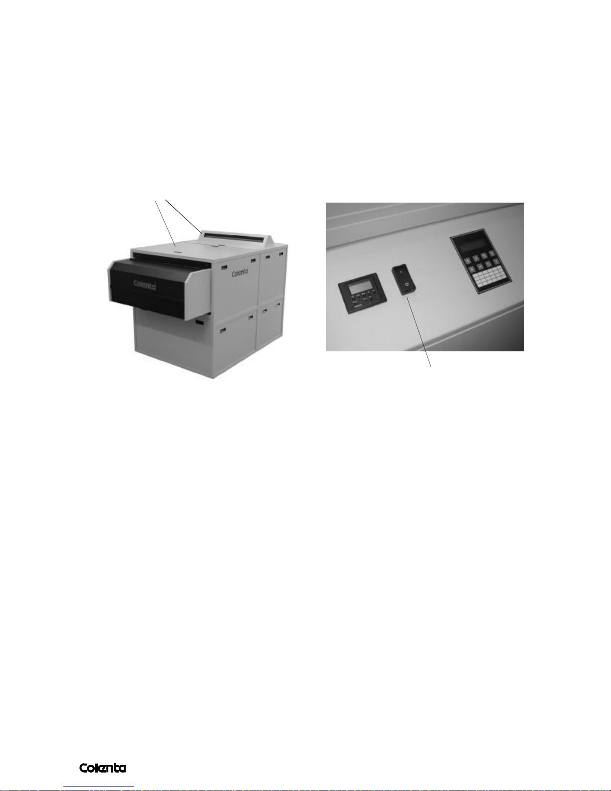
*) Only the Top Cover of the Filmprocessor may be removed by the operator (see picture
below)
.
*) The film processor must be separated from mains prior to carrying out any maintenance. To
do so, switch the mains switch of the machine to „0“ position. Always wear safety goggles
and protective clothing when handling chemicals.
Top covers
Main switch of
the film processor
*) The filmprocesor may not be in operation without supervision.
*) Make sure that clothing or other objects cannot get entrapped in gear drives or similar of the
film processor.
*) The installation, service, repair as well as the initial operation of the machine may be carried
out by qualified and trained service personnel only.
*) Built-in safety devices may not be eluded or made inoperative. Use only original COLENTA
spare parts when exchanging failed electrical components.
*) Do not wear any loose necklaces or bracelets!
1.2 CHEMICAL HANDLING
*) Observe all safety technical regulations of the chemical manufacturer.
*) Wear safety goggles and protective clothing when handling chemicals.
*) Ensure proper ventilation of the room in which the chemicals are prepared.
*) Spillage or overflow of chemicals has to be removed instantly.
*) In case of contact with the eyes flush with plenty of cold water for approximately fifteen
minutes and consult an physician.
*) Chemical disposal has to be in accordance with the local environmental codes. Contact your
local water treatment and sewer district authorities for more information.
Page 7

AN 06/2003
page
1.3 IMPORTANT WARNING AND SAFETY INSTRUCTIONS
3
(Please read these instructions carefully.)
Processor Operation
Make sure that no long hair, loose clothing or
jewellry can get entrapped in the gear drives
or in the media transport area.
The „Service Manual for Colenta Printline
Processor" is for the use of qualified
service personnel only.
The racks must be cleaned with running
water outside the Film Processor.
Do not clean the processor with running
water.
Electrical and Mechanical Hazards
Observe all safety warnings to minimize the risk of
electrical shock,burns or equipment damage.
Photographic Processors are complex
machines with many electrical and mechanical
parts as well
as with a considerable amount of chemicals.
2).When handling chemicals wear protective
clothing, safety goggles and rubber gloves .
3).Label storage containers properly.Avoid
storing hazardous chemicals on high
shelves or in unprotected glass containers.
Keep chemicals away from children.Do
not store chemicals in a refrigerator used
for food because they may contaminate
food or be mistaken for edibles.
4).Ensure proper ventilation in the area where
chemicals are used or stored.
5).Observe the manufacturer’s recommendations for using and mixing chemicals.
Overexposure to photographic
chemistry may cause skin irritation to
certain individuals.
PHOTOGRAPHIC CHEMICAL EMERGENCIES
AND FIRST AID PROCEDURES:
Fire Prevention
The area around the processor must be kept
clean at all times. Keep dust ,wood shavings,
scrap paper or other inflamable materials out
of the dryer compartment.
Fire extinguishers must be available in the
room where the processor is installed.
Chemical Handling and Accident Prevention
Misuse of almost any chemical may create
a hazard of some type.Generally photo chemicals
are not any more dangerous as most of the regular
cleaning agents. However, there is always a residual
risk. When handling chemicals observe the procedures
below.
1).Never sniff a container or open bottle to
determine its contents. A cautious sniff of
the cap or lid is safer.
• SKIN - Rinse thoroughly with water.
• EYES -Rinse thoroughly with water and
consult a physician.
• INGESTION -Consult a physician imme-
diately.
Page 8
AN 06/2003
page
Chemical Disposal
4
Waste from photographic processing normally
contains diluted chemicals. These chemicals
should be collected and disposed in accordance
with local environmental codes.Dumping
chemicals into a drain system could lead to a
pollution problem.Contact your local water
treatment and sewer district authorities before
disposing chemicals.
All plumbing must comply with local and
national codes.The DRAIN must be made of
chemical resistant and non-corrosive material.
Use PVC or equivalent
Exhaust,Temperature and Humidity
It is necessary to ensure proper ventilation
in order to receive good processing results.
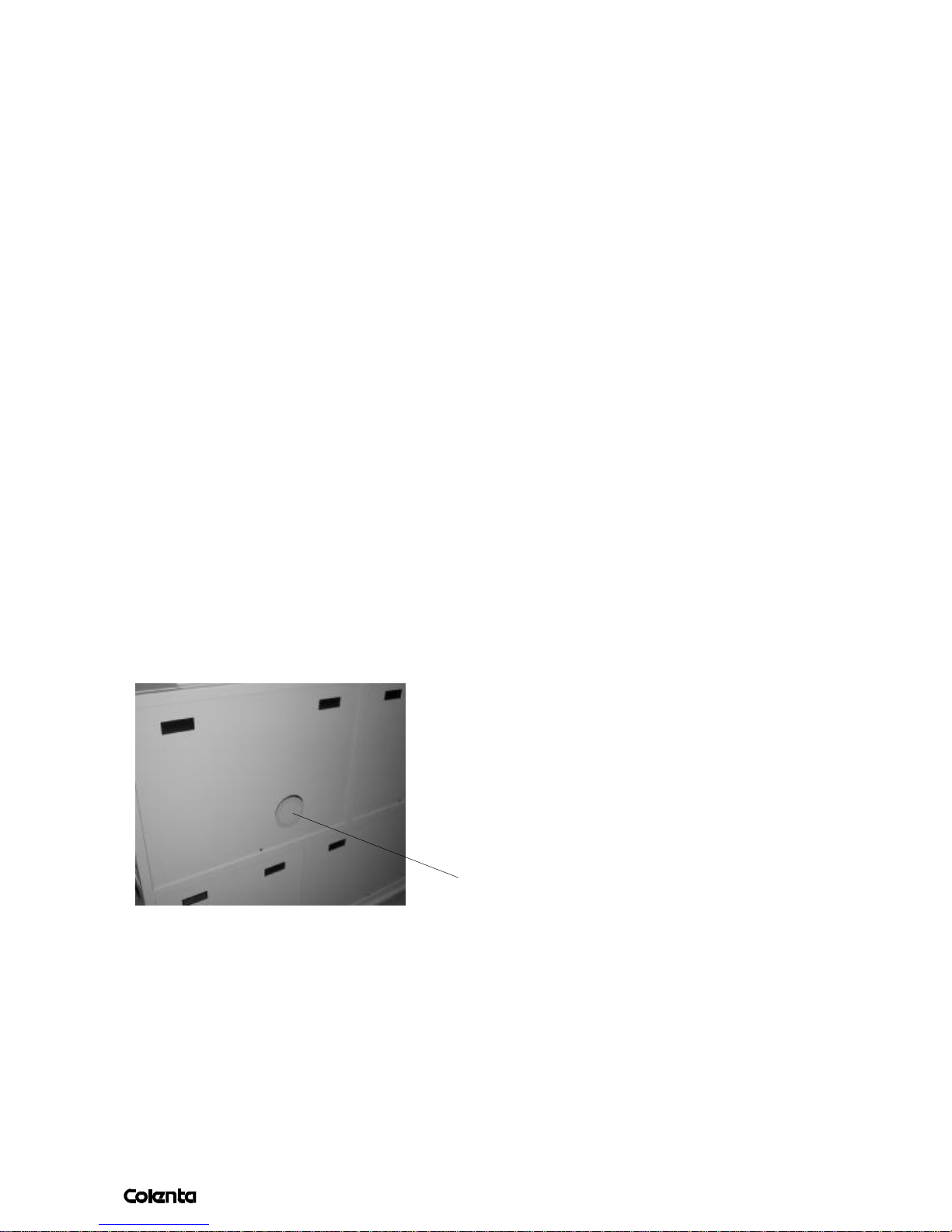
Make sure that the exhaust hose of the
built-in exhaust fan is properly connected
to the exhaust air socket (Picture 1).
The built-in exhaust fan exhausts the
fumes from the processor.
These chemical fumes are corrosive. The top
cover of the processor should be removed over
night.
· High voltage may cause electric shocks,
burns or even death.
· Hands or fingers may be pinched or
injured by moving parts or when handling
heavy parts.
· Dryer compartment heat may ignite
combustible materials and cause fires.
· Eyes,skin and lungs may be irritated
by photo chemicals.Before using photo
processing chemicals always read the
Material Safety Data Sheets (MSDSs)
for information about the hazards of
the particular chemicals and how to use
them safely.
· Do not operate the film processor after
consuming alcohol or taking strong
medication.
· Do not wear jewellery or loose clothing
when operating the processor.
Room temperatures between 18-26 °C
(65-80 °F)with a relative humidity between 35%
and 75%are ideal for photographic processing
and working.
Picture1
The filmprocessor is a complex
machine with moving parts such as the gear
train and media transfer components.It uses
photo processing chemicals which are irritating
to eyes,lungs and skin.High voltage is used to
power the processor.
Electronical and Electrical Hazards
HAZARDOUS VOLTAGE CAN CAUSE
ELECTRIC SHOCK,BURNS OR EVEN
DEATH ·
Qualified service personnel must verify during
installation that the processor is permanently
and reliable grounded according to
standards in the National Electrical Code.
Air grille
The dryer compartment produces heat.
Page 9
AN 06/2003
page
Carry out the following steps prior removal
5
of the top cover:
1.Train operators of the processor.
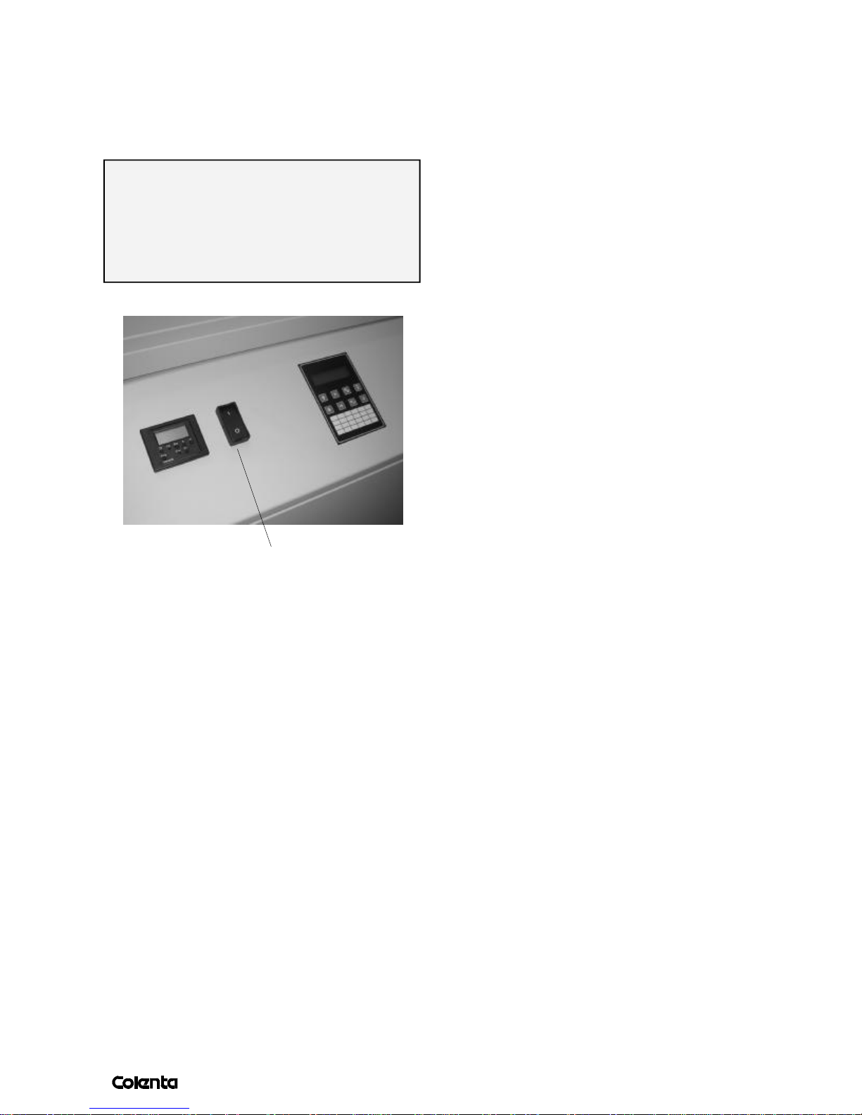
2.Switch off the main power switch
(„0“-position) and secure against
restart by locking with a padlock
(see picture below).
Burn Hazard
DRYER COMPARTMENT PRODUCES
HEAT -DRYER PANELS AND GUARDS
GET HOT
· Therefore do not touch dryer panels or guards
when dryer in operation
Corrosive Liquids
CHEMICALS MAY IRRITATE EYES,
LUNGS, SKIN AND DIGESTIVE TRACT
# Wear safety goggles,protective gloves and
chemical aprons as indicated on Material
Safety Data Sheets (MSDSs)when handling
chemistry.
# Drain tanks carefully,avoid splashing.
Always drain the system thoroughly before
working on any of the external hose systems.
# Read the MSDSs for more information
regarding the proper safety procedures for
working with photo processing chemicals.
Main switch of
the processor
Fire Hazards
DRYER COMPARTMENT PRODUCES
HEAT -PAPER OR OTHER COMBUSTIBLES CAN BE IGNITED
· Keep the area within 10 feet of the processor
clean.Do not store combustible materials,
including paper, close to the filmprocessor.
· Verify that a functional 10 lb.ABC fire
extinguisher is located closed to the processor.
# Do not allow untrained personnel to handle
photo processing chemicals or to operate
the filmprocessor.
# To avoid hazardous situations,keep floors
and floor coverings around the processor and
associated drains clean and dry at all times.
Any accumulation of fluids outside the film
processor, should be cleaned up
immediately
Page 10

AN 06/2003
page
In the event of an accumulation
6
of liquid due to backup,overflow or other
malfunctions of the drain associated with the
processor call a plumber or other contractor
to correct the problem with the drain.
Colenta assume any responsibility or liability
whatsoever for the service ability of any
drain connected to the processor.
Such drains are the sole responsibility
of the customer.
DRAINS must be made of chemically
resistant and non-corrosive material.
Chemical Hazards
Chemicals can be the source for errors,
contaminate the waste water, irritate skin
or eyes.
Spills must be cleaned up immediately as
follows:
1.Prevent the spilled chemicals from entering
a waste water drain.
Corrosive Vapours
CHEMICAL VAPOURS MAY IRRITATE
EYES,LUNGS AND SKIN IF ALLOWED TO
ACCUMULATE IN WORK AREA
Assure an adequate supply of fresh
outdoor air through natural or mechanical
ventilation.
· Make sure that qualified service personnel
is checking the external exhaust system at
regular intervals.
· Read the Material Safety Data Sheets
(MSDSs)for more information regarding
the proper safety procedures for working
with photo processing chemicals.
2.Clean up the spill with a moist mop or rag.
CAUTION!
When handling chemicals, especially fixer,
wear protective clothing, safety goggles
and rubber gloves.
If processor chemicals make contact with the
eyes,rinse them thoroughly with lots
of water.If irritation persists,consult a physician.
3.Dispose cleaning materials and collected waste
water from the clean up according to
environmental regulations and locals codes.
4.Avoid any inhalation of chemicals as
this is dangerous to health.
5.Observe all environmental regulations for
storage and disposal of waste chemicals.
6.Use this manual together with the
instructions for chemicals.
When handling chemicals wear
protective clothing, safety goggles and rubber gloves,
Page 11
AN 06/2003
page
2.BEFORE INSTALLATION
7
Site preparation should be completed before delivery and installation.
2.1 LOCATION
Location. All dimensions for the processor are detailed in the technical data sheet.
It is important that the processor location is well ventilated and with the required air
changes per hour – follow all recommendations from the chemical supplier.
We recommend a minimum walking space of 60cm around the processor.
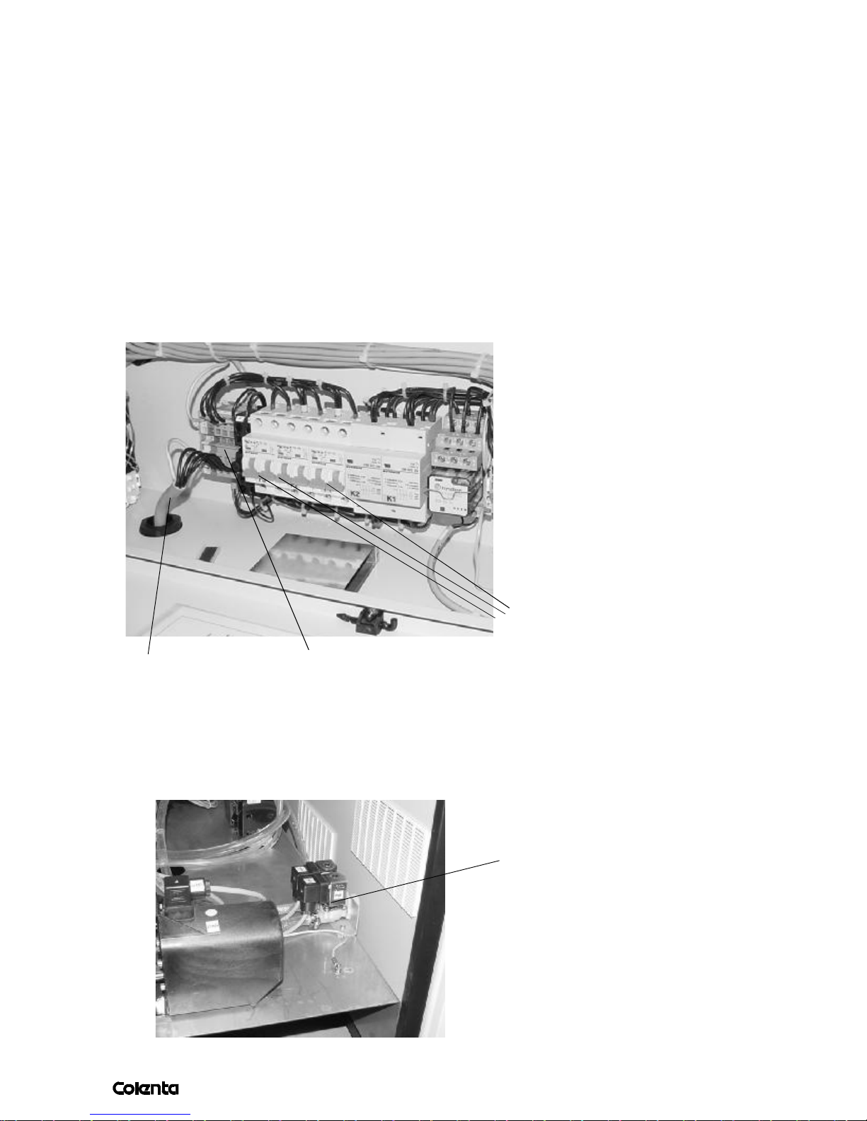
2.2 ELECTRICAL SUPPLY
*) All electrical connections must meet national safety requirements. Correct fuses and
electrical requirement can be taken from the processor specification/data sheet.
inline circut breaker
power cord
2.3 WATER SUPPLY (OPTIONAL)
It is necessary to connect the processor directly to a fresh water supply for cooling
and rinse. To do this, locate the installed 2-way magnetic valve. See the picture below:
We recommend that a water supply (preferably warm water) and working area are
available close-by to the machine for the purpose of cleaning rollers and tanks.
multi terminal block
Magnetic Valve
Page 12
AN 06/2003
page
3. TRANSPORT AND ASSEMBLY
8
To carry the processor to the working area, take care to the points below:
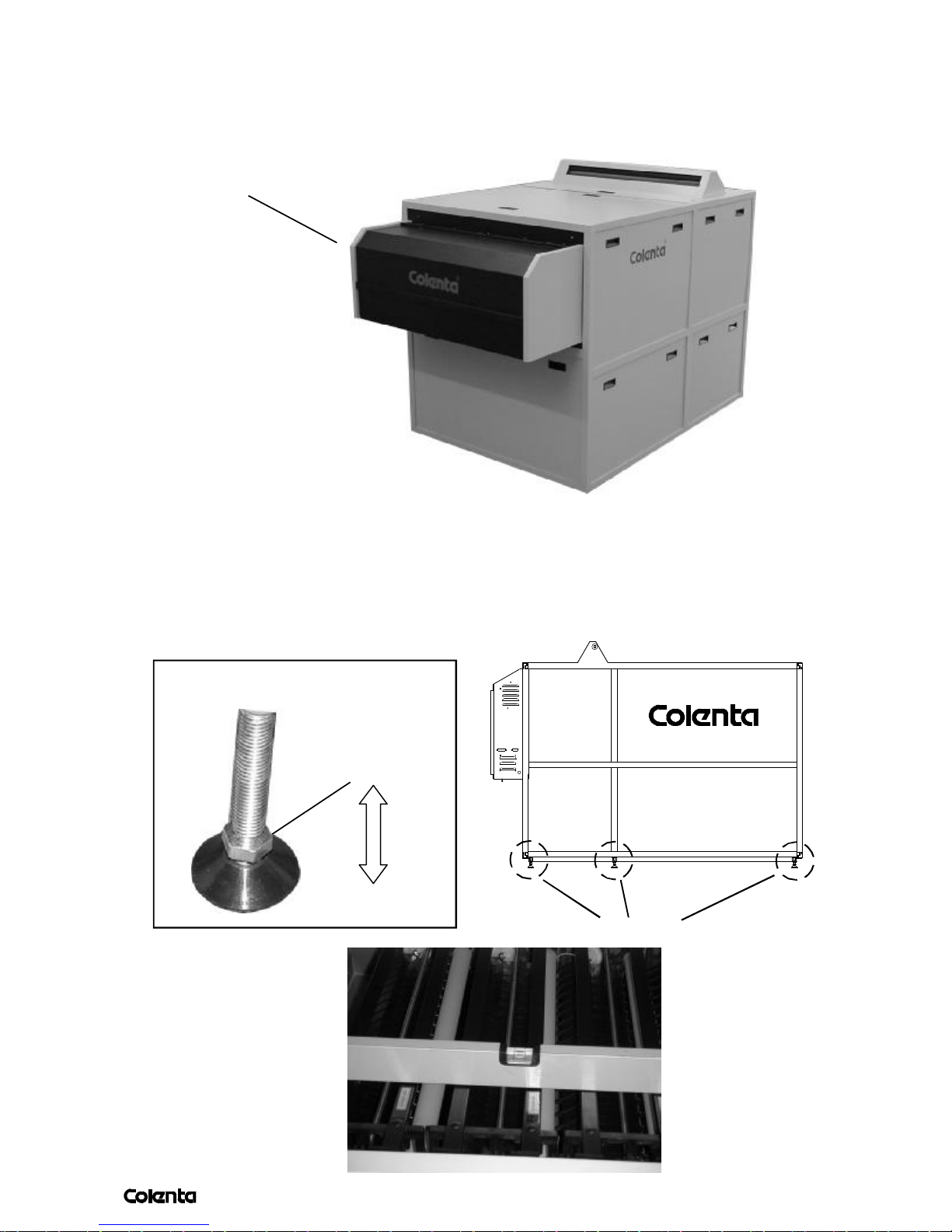
Processor
- take out the racks and the dryer during carry the
processor
- take off all kind of panels and covers
- move the Chiller unit separately (optional)
After re-assembly and with the maschine in position - level the unit for the optimum
performance - use a good quality leveling device.
Level foot
Key no.13
Level foot
Page 13
AN 06/2003
page
9
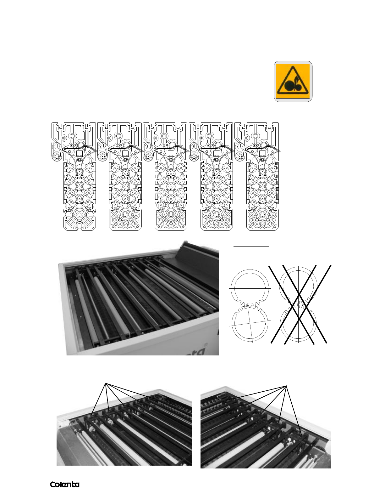
3.1INSTALLATION OF THE TRANSPORT RACKS
The processor is deliverd completely assembled. Exept the transport racks, the dryer
unit and the external chiller unit has to be installed. Follow the illustrations below to do that:
*) Take care that all transport fixings are removed
*) Remove all packing materials
*) Insert the racks according the reference number or label
*) Avoid any splashes of chemistry
DEV BF SS1 SS2 SS3
Don't forget
to fix the racks!
Attention:
Take that all gears are installed
as shown.
Don't forget
to fix the racks!
Page 14
AN 06/2003
page
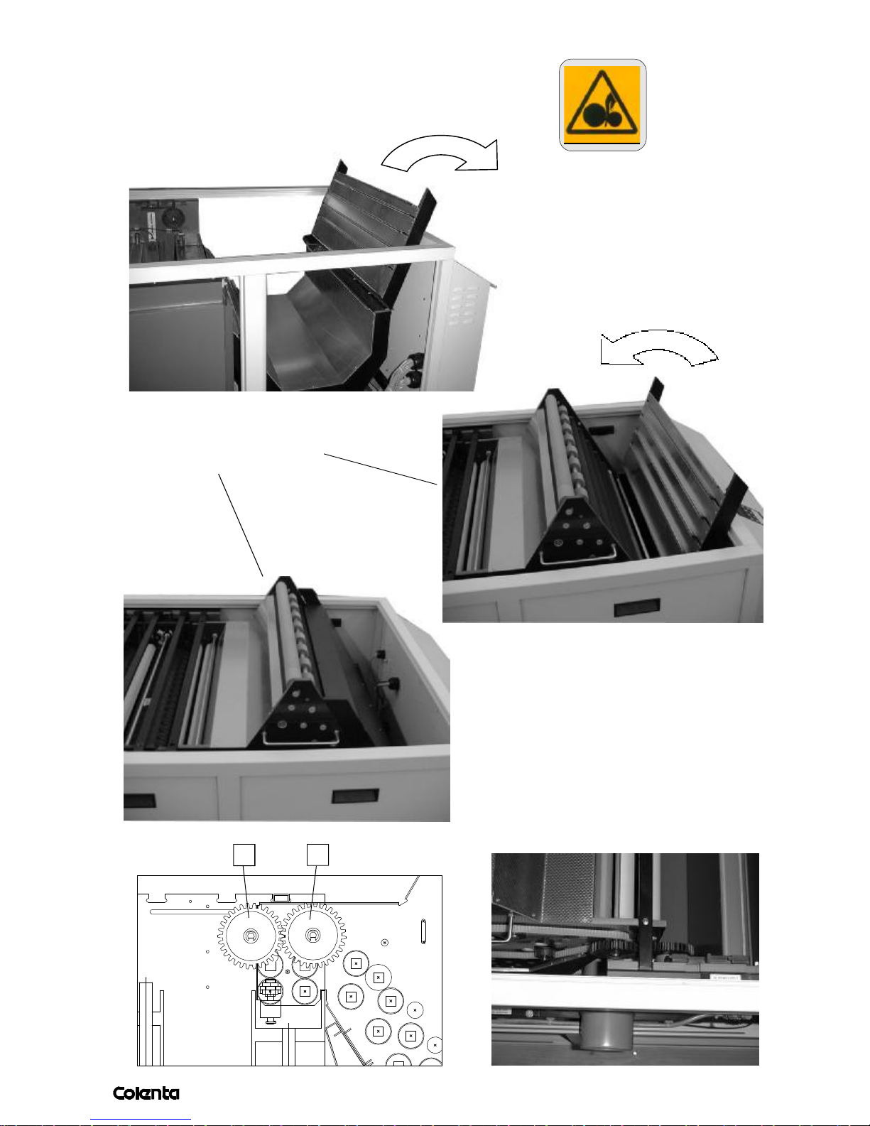
3.2INSTALLATION OF THE DRYER
10
Follow the illustrations below to install the dryer:
2. Put the dryer in and
close the dryerlid.
1. Open the dryerlid.
1 2
3. Check the position
of the drive gear.
1...Drive gear / Chain
2...Drive gear / Dryer
Page 15

AN 06/2003
page
4. PROCESSOR FUNKTIONS:
11
4.1 PROCESSOR FUNCTIONS
PROGRAMMING: Automatic processing parameters, e.g., temperature, speed and
replenishment rates, can be stored in 9 different programmes.
WARMING-UP: Once programmed, temperature settings are accurately controlled.
Heating commences with switching on at the mains. Constant solution
temperatures are maintained in the processing tanks. Temperatures
tolerances +/- 0,2 °C are achieved by the microprocessor control unit
while the solutions are circulated by circulation pumps. When
temperature has reached PRE-SET levels, the processor enters
STANDBY mode and is ready for use.
WORK MODE: Is when all process parameters are reached (as programmed
before). In this condition the machine confirms READY
SLEEP MODE: Sleep mode is an automatic feature for monitoring and keeping the
chemistry in good order. It is activated during night and weekend
times when the machine is inactive i.e. periods when the machine will
not be used for production and when standby replenishment is disabled.
ANTI CRYSTALLI- During STANDBY mode - within a programmable cycle periode - transport
ZATION CYCLE is activated - this prevent cristallization build up on crossover rollers.
ANTI-OXIDATION During STANDBY mode - and no material is processed during set time CYCLE an preprogrammable ANTI OXIDATION cycle (replenishment cycle)
is available.
The additional replenishment compensates the impact of airoxidation of
the chemistry during standby mode und tops up the chemistry
levels in the tanks, compensating evaporation of the water in the
solutions during standby.
AUTO The processor comes equipped with a media area measuring facility.
REPLENISHMENT: Infrared sensors scan the material area touchless and when
the preprogrammed amount of material (area) entered the processor,
a replenish-cycle is activated.
AUTOMATIC Infrared sensors also automatically control the startcycle of the
START-STOP: prosessor. The processor changes from STANDBY to RUN once material
has interrupted the light barrier. As the rollers turn, water is supplied to
the wash tank and to the intermediate rinse bath system. Once the last
film has passed through, the processor reverts to STANDBY. The film
can be taken out of the receiving basket or top cover lid.
4.2 SAFETY DEVICES
*) Thermostatically controlled solution heater with overheating CUT-OUT and AUTO-RESET.
*) Thermostatically controlled dryer heater with overheating CUT-OUT and MANUAL-RESET.
*) All electric motors are equipped with thermal CUT-OUT and AUTO-RESET.
*) Each electrical component is protected by a fuse on the power distribution board (PDB).
Page 16
AN 06/2003
page
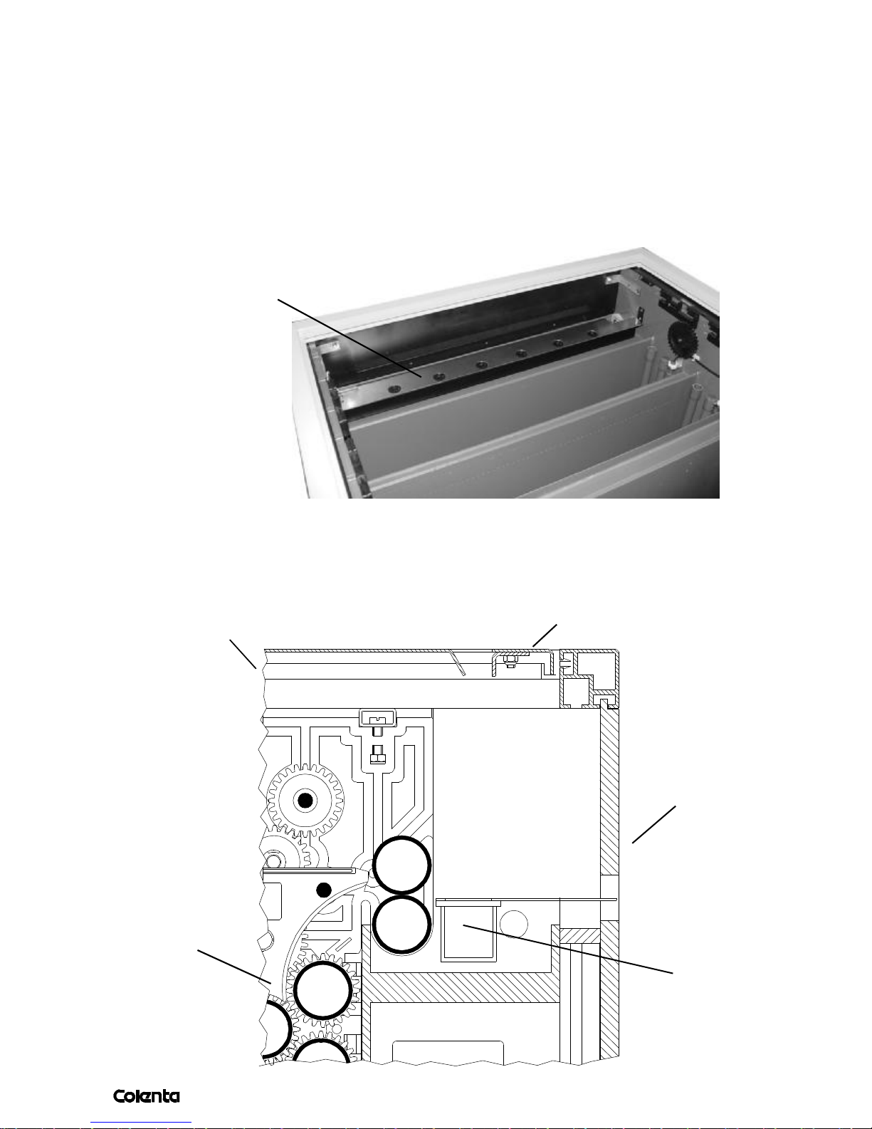
5. INFEED - SENSOR BAR
12
An infra red sensor bar assembly is located at the entrance to the processor. As soon as
media passes across the sensor bar a process cycle is initiated which in turn starts the
transport motor and triggers timing circuits for the control of ”timed” processing sequences –
wash off, standby, dryer on. Timed sequences are set to operate to pre-programmed
automatic requirements and are also used for providing a visual reference on the material
location as it passes through the processor.
Infeed-Sensor Bar
Important: Special care must be taken to ensure that the processor entrance rollers are
always clean and dry – any spillage of chemical or water onto the feed tray / feed rollers
or sensor bar must be avoided. Any spillage must be cleaned immediately.
Frame
Developerrack
Cover
Flatfront
Infeed-Sensor
Bar
Page 17
AN 06/2003
page
13
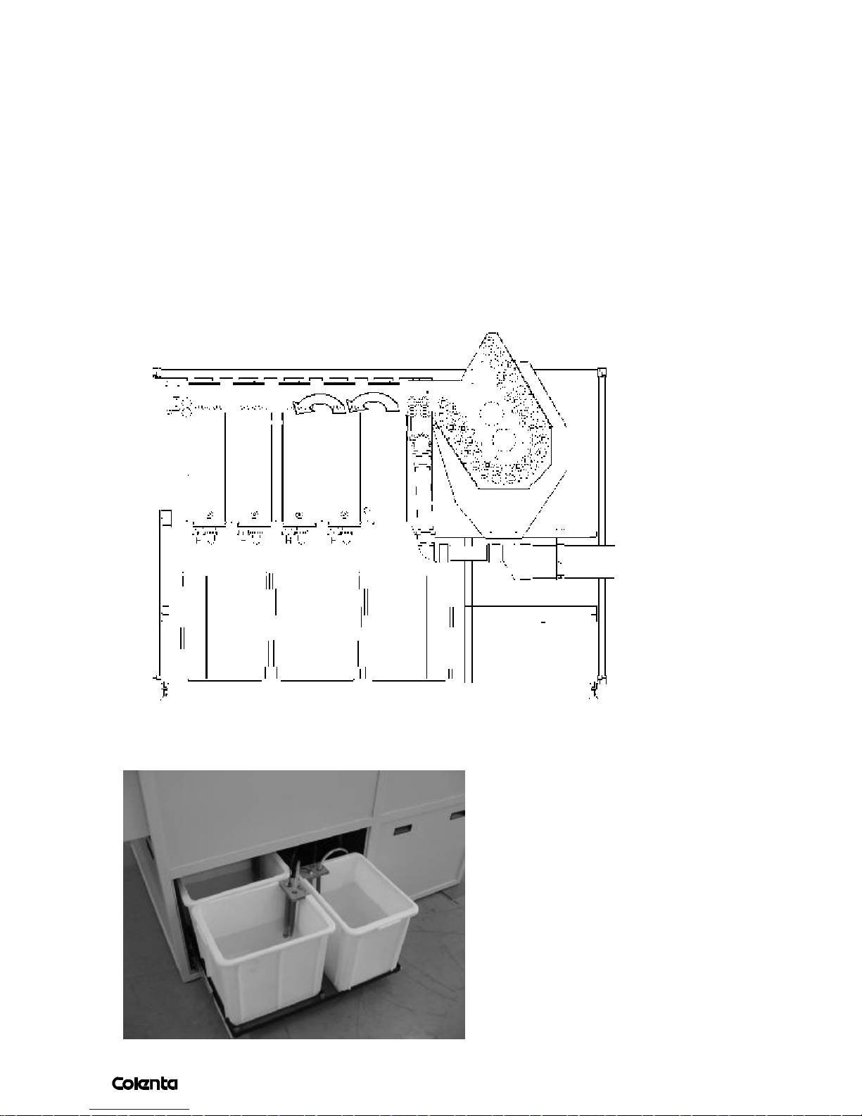
6. CHEMICAL REPLENISHMENT SYSTEM
When operating a processor which uses chemicals for the continuous production of paper it is
very important that the chemicals within the machine are keep in good working order so as to
provide consistent processing quality. To achieve this consistency we use replenishment
solutions, which are formulated by the chemical manufacturer and injected into the processor
precisely for the area of material being produced. Replenishment of the chemical tanks is done
automatically using infra red sensors located at the entrance to the processor. These sensors
accurately monitor the width of material entering the processor, this information is then used by
the microprocessor (CPU) control software to calculate the surface area for each sheet loaded
into the processor.Each sensor, when covered, will generate a pulse, which is then recorded on
a decoder and counted – the more sensors that are covered then the faster the count. When the
count reaches the programmed value of pulse counts it triggers the start of a replenishment
cycle. During each replenishment cycle the replenishment pumps inject fresh solution from
small storage bottles/tank and into the corresponding ”working” tank solutions for a pre-set time.
DEV BF SS1 SS2 SS3
DEV BF SS
NOTE: TankSS1, SS2 and SS3 are connected (Overflow Cascade system)
3x30 replenisher tanks with
level control
DEV
SS
BF
Page 18
AN 06/2003
page
14
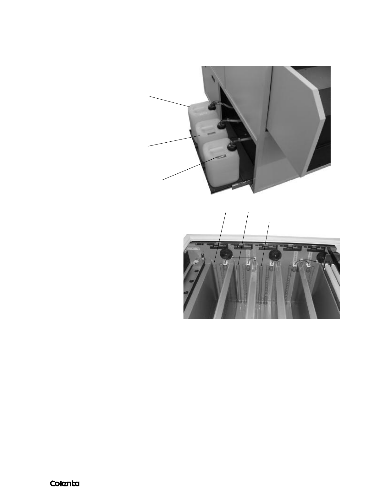
6.1DRAIN CONNECTION
It is not necessary to connect the processor to an external drain facility – the processor is
supplied with 3 x 10 litre container which are used to collect the waste Developer, Bleachfix and
Superstabi solutions. The containers are fitted with a high-level alarm device, when full they have
to be emptied.
Levelsensor
(Highlevel)
SS
BF
Levelsensor
(Highlevel)
Levelsensor
(Highlevel)
DEV
The waste tanks are filled in two ways:
• manually, by opening the overflow
pipes in the tanks (to drain the tank)
Overflow DEV
Overflow BF
Overflow SS
• automatically, through the overflow
pipes in the tanks.
Full waste tanks have to be collected
by an authorised waste treatment
company.
The above mentioned level sensor is used to control the level inside the waste container.
In case one of the sensors is recognizing high level, the processor will bring the message
"WasteX high level".This indication informs the operator that the waste container must
be emptied or replaced with a fresh empty tank.
6.2WATER DRAIN (OPTIONAL)
As mentioned before, in case the processor is supplied with as a non-washless
version,the corresponding drain-tube has to be connected.
Page 19
AN 06/2003
page
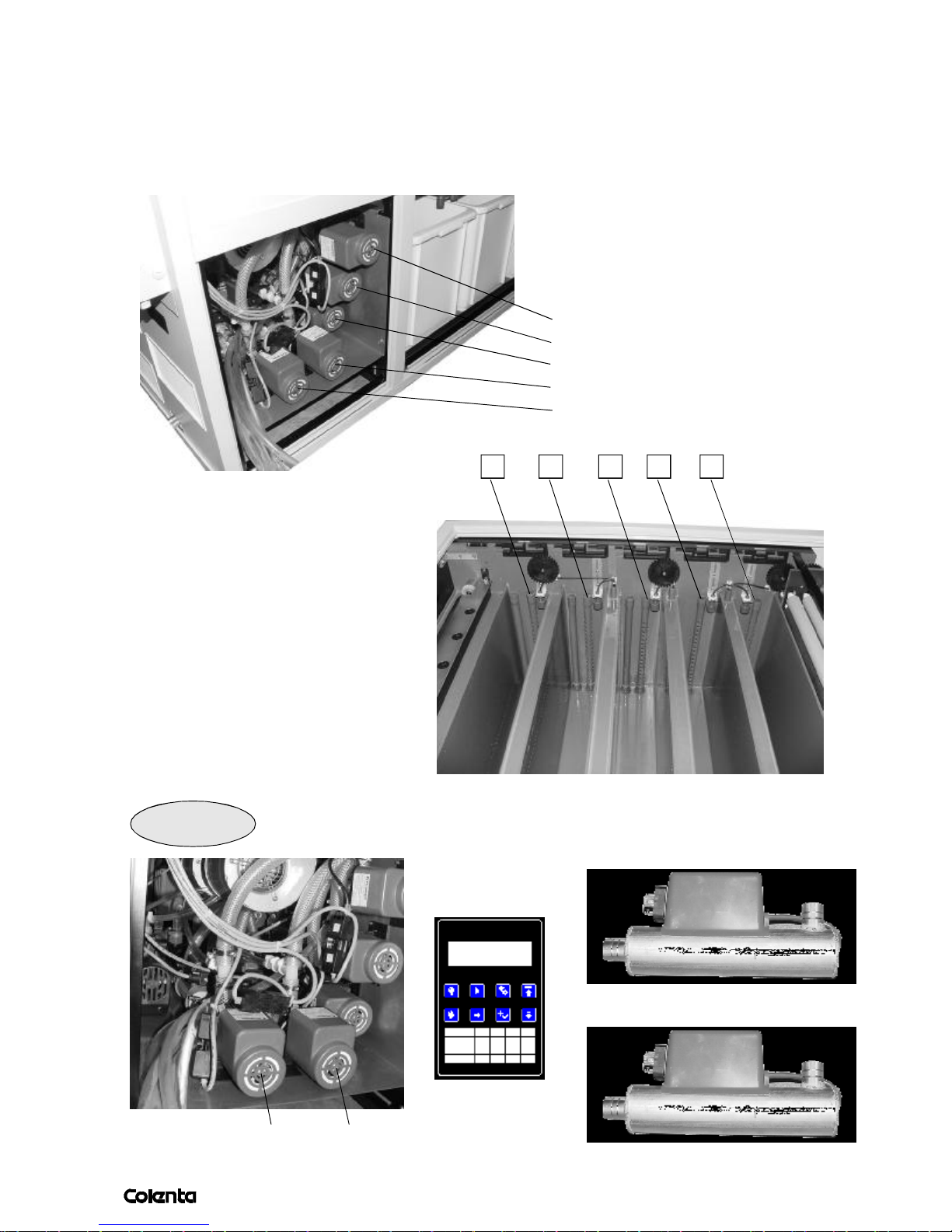
7. HEATING / COOLING / CIRCULATION
15
The working temperature of all solutions is accurately monitored and electronically
controlled to the precise pre-programmed specifications. Each solution is heated by a
dedicated heat exchange ”flow heater” unit located in the circulation lines, which provides
an efficient heating system with low maintenance requirements.
Circulation pump Superstabi 3
Circulation pump Superstabi 2
Circulation pump Superstabi 1
Circulation pump Bleachfix
Circulation pump Developer
54321
1-Circulation tube Developer
2-Circulation tube Bleachfix
3-Circulation tube Superstabi 1
4-Circulation tube Superstabi 2
5-Circulation tube Superstabi 3
Dev & BF
Heat exchange ”flow heater”
DEV
Microprocessor
Heat exchange ”flow heater”
DEV
BF
BF
Page 20
AN 06/2003
page
16
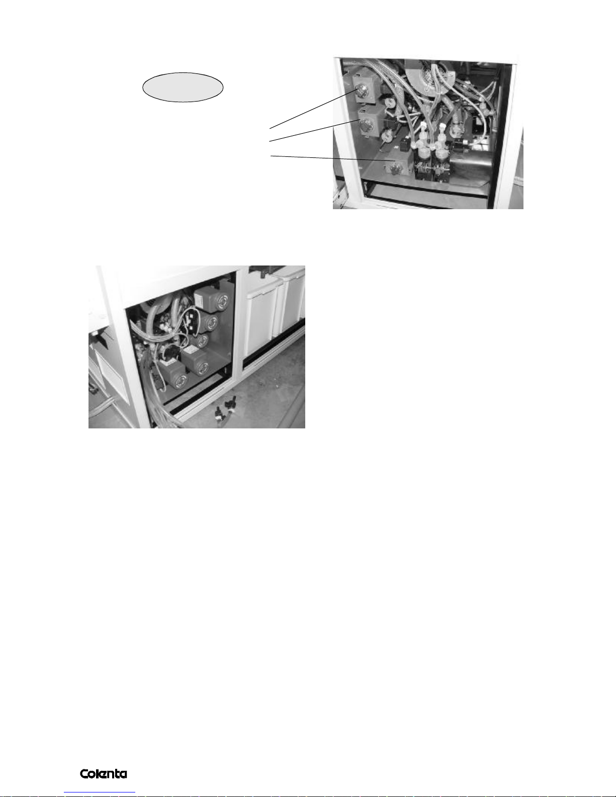
To adjust the temp. for the SuberStabi1,2 and3, use the external thermostats
pointed below:
Superstabi
External thermostat Superstabi 3
External thermostat Superstabi 2
External thermostat Superstabi 1
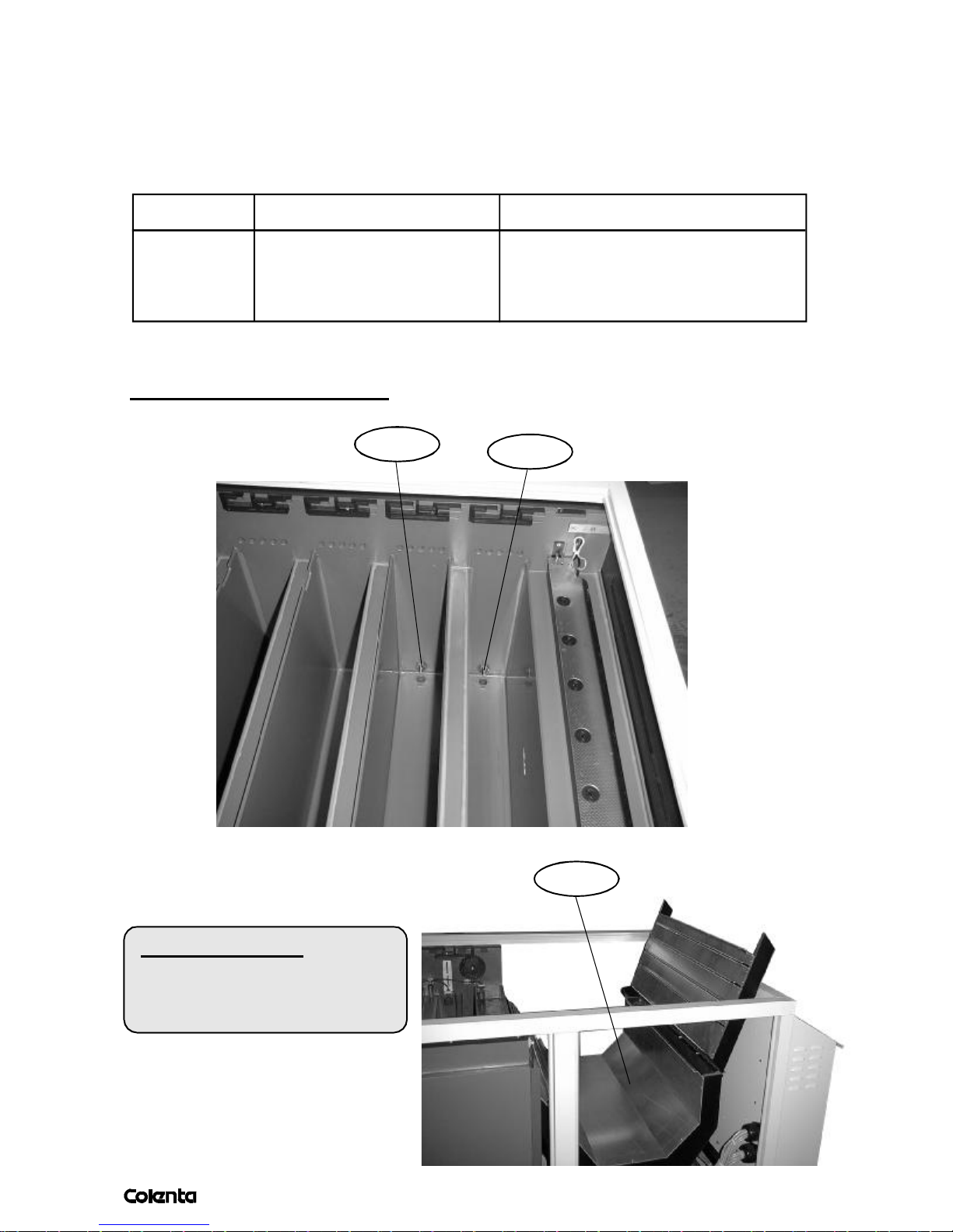
7.1 HOW TO DRAIN THE PROCESSOR
To drain the tanks, remove the side panel,
open the stop cock of the corresponding
tank.
Page 21
AN 06/2003
page
7.2 TEMPERATURE CONTROL
17
Probes positioned under solution levels precisely monitor all solution tank temperatures.
These temperature probes are continuously supplying information to the microprocessor
on actual solution temperatures within the tanks. The microprocessor then compares these
actual temperatures to the required programmed ”set” temperatures and controls the relevant heaters/cooling systems accordingly.
Bus-System Measurement Action
Temp.-probe Developer Temp. Heating/Cooling
BleachFix Temp. Heating/Cooling
Sensorbar Incomming media area Replenishment
NOTE:To transfer this information, a BUS-SYTEM is installed.
Position of the temp.-probes:
BF
DEV
DRY
COLOUR CODE
DEV(T1)......................Yellow
BF (T2)........................Blue
Dry (T3).......................Red
Page 22

AN 06/2003
page
8. TEST RUN AND TANK FILL ( RECOMMENDED)
18
IMPORTANT: Although all processors are thoroughly water tested before delivery, we would
always recommend to check all hose and tank connections in case a fitting becomes loose or is
broken during transportation. In the case of transport damage - this should be recorded on film
and reported to the shipping company. To check, it is recommended to fill the processor firstly
with water.
- Remove all packing materials / transport fixings
- Insert the dryer (see page 6)
- At the moment, put transport racks aside.
- Check that all drain valves are closed (see page 12)
- Now fill all the tanks with water until the red marks inside the tanks are reached.
- Insert the transport racks slowly and carefully. Aviod any splashes. (see page 5)
- Fix the racks as pointed out on page 5
- Switch on the processor
- Now all pumps/heating elements will start to work. Check now very carefully all connections
and fittings. Run the unit approx. 10 min. Also during that, check the display and the
progressing temperature rise.
- See page 23 how to start the processor transport by hand - check the rotation of the
racks and the dryer.
- Fill the replenishment tanks with water as well - see page 22 how to start a replenishment
cycle by hand. Start Repl1 and Repl2 - see page page 10. All replenishment pumps have to
run now.
When the processor is turned on (Electrical power applied) the microprocessor will first look at the
position of all level switches to be sure all solutions are at the required level. If OK the pump and
heating systems are energized. After approx. 25 minutes the solutions will be at their pre-set required
temperatures and the processor will confirm P1 READY – the processor is now ready for operation.
If the level in any tank is low then the display will inform – TANK X Low Level and the related pump
and heating system are disabled for safety.
9. WORKING WITH THE CHEMISTRY
Firstly we recommend to contact your local chemistry representative office
on all matters relating to chemical mixing handling using.
- Switch off the processor.
- Drain all tanks of the processor (page 12)
- Take out the racks of the processor
- Take care that all tanks are dry and clean, close all valves again.
- Use the replenishment container (30L) for mixing the chemistry or other recommended
mixing systems
- Fill the tanks with chemistry until the red marks inside the tanks are reached. The remaining
liquid in the containers can be used for replenishment.
- Switch on the processor - follow the instructions on page 16,17,18
Page 23
AN 06/2003
page
9. WORKING WITH THE PROCESSOR
19
in the morning:
- Check all chemical levels - processor tanks and Replenishment storage
tanks - top up if necessary. If the process controller detects a „low level“
in the Developer and Bleach processor tanks then add small amounts of warm
water.
- Check the levels in the overflow „waste“ containers - empty if necessary.
- Place the processor from „Sleep“mode into production „Work“ mode.
When the machine reaches its „Ready“ state it is recommended to load and
read a process control test strip before running calibration or production
prints.
normal working : (Program: P1 READY)
- Operate the machine for the production of RA4 Paper and Display film only.
- Allow materials to automatically exit the dryer
in the evening:
- Empty the waste collection containers
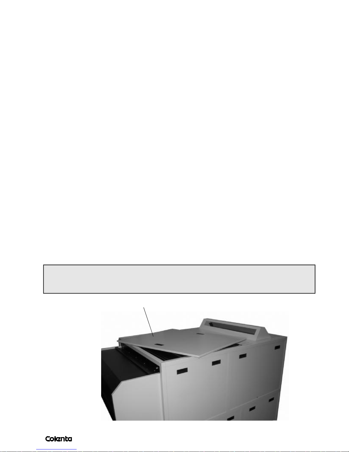
NOTE : In a situation where local laws / building laws / insurance reasons do not allow the use
of a Sleep mode during the nights and weekend periods then it will be necessary (with the
processor off) to open the 1
st
top cover to prevent condensation inside the processor.
Top Cover
Page 24
AN 06/2003
page
20
11. USING THE CONTROL PANEL
Generally, all settings which are necessary for high qualitiy processing results,
are already programmed. Re-programming should only be undertaken by
approved authorized personnel.
The control panel is used by:
- operator: to monitor the processor, and to select special function (Manual function
mode)
- technician: to set/or to change the processing parameters
Specifications
Tank1 time [sec] 032 - 190
T1 [°C] DEV 15,0 - 45,0
T2 [°C] BF 18,0 - 55,0
T3 [°C] SS1 18,0 - 55,0
T4 [°C] SS2 18,0 - 55,0
T5 [°C] SS3 18 - 60
R1 [ml/sqm] DEV 0040 - 2000
R2 [ml/sqm] BF 0040 - 2000
R3 [ml/sqm] SS 0040 - 2000
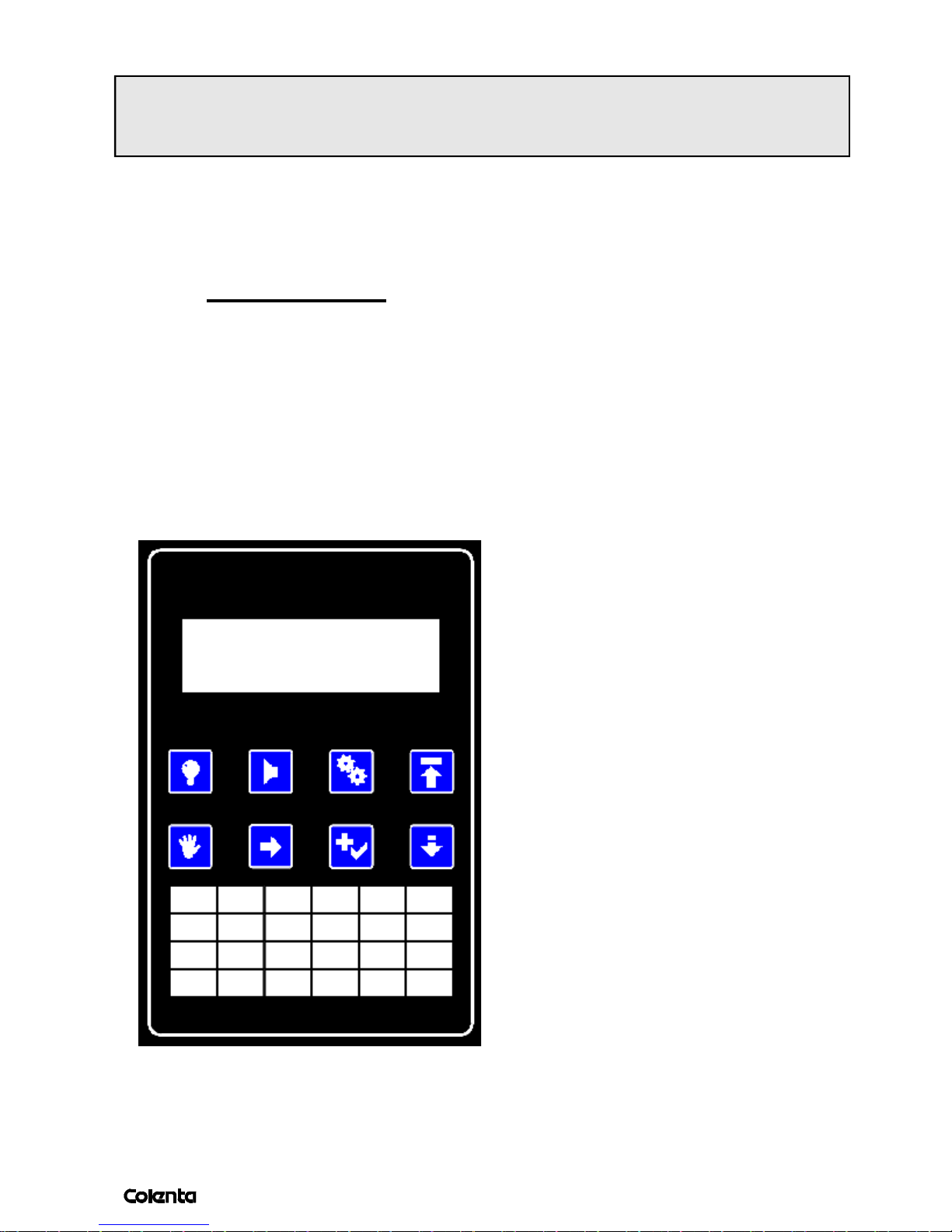
The display
1 back light ON/OFF
2 check errors /alarm shutdown
3 setup mode
4 back to top menu
5 manual operation
6 move cursor
7 select menu item/change value
8 scroll page down
Page 25
AN 06/2003
page
21
11.1 AFTER SWITCHING ON
After the processor is installed and with all the components and service in place, switch
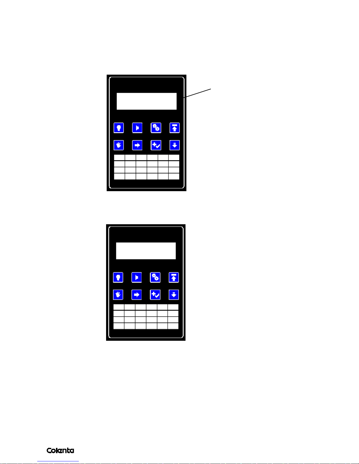
the processor on. The controller display will illuminate and confirm the software revision
monentarily.
version of program
MF 700 5.1r04
After the initialization-cycle is complete (it takes 2-3 sec.) the processor will start in
program1 (P1)
P1/Er Ready
T1=19,1°C (22,0)
P1 indicates that programme1 is in use and will operate to the programed values set in
programme1. Everytime when switching on the processor will start using P1. The blinking
Er sign (Error) informs the operator of any Error, use 2to see what kind of error the
processor is confirming. In case there are more than one error, use 8 to scroll throuhg the
pages. Use
4to jump back to the main page of the display.
Page 26
AN 06/2003
page
22
11.2 POSSIBLE ERROR CODES AFTER SWITCHING ON
1. Cover open Cloes the cover of the Processor (Cover switch)
Close the cover of the processor.
In case the processor is switched on with no chemistry in the tanks, you will get
the following messages:
Level switch for tanks
2. Tank1 LowLevel(DEV)
Tank2 LowLevel(BF)
Tank3 LowLevel(SS1)
Tank4 LowLevel(SS2)
Tank5 LowLevel(SS3)
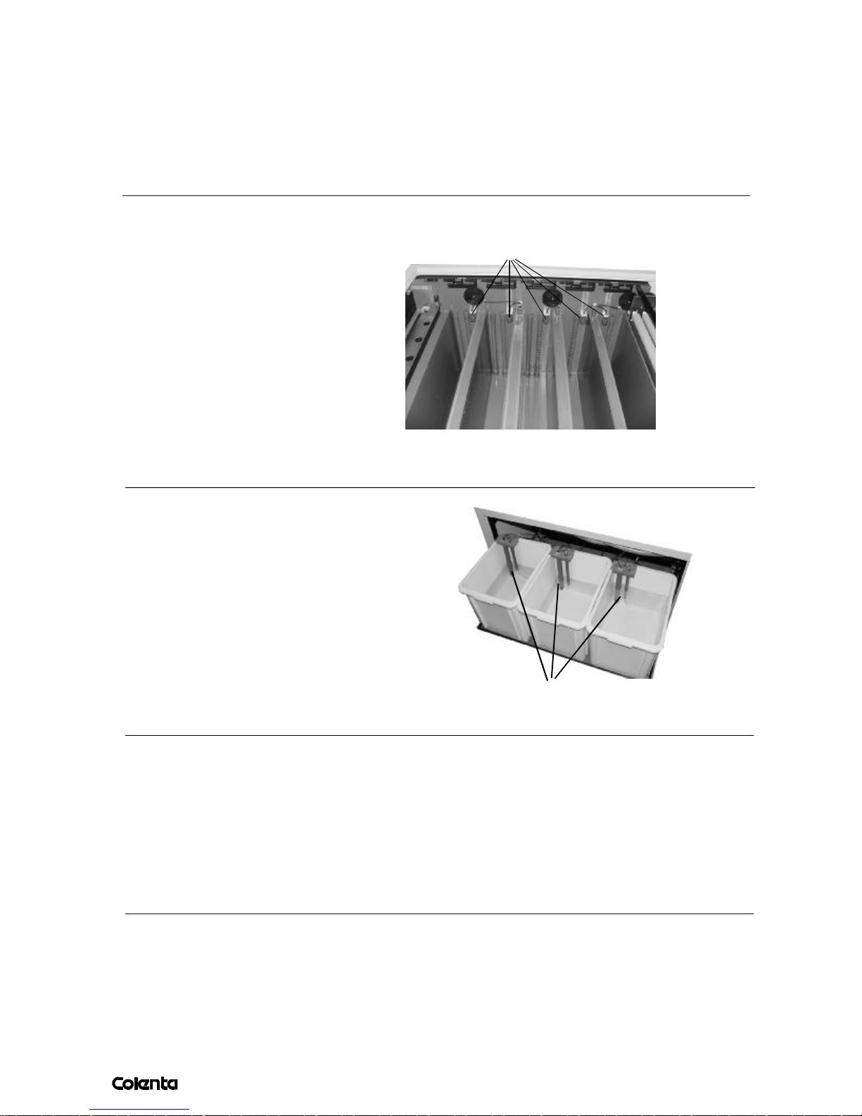
Fill the tanks according page 17 to remove the above error codes.
3. Rep1 low level (DEV)
Rep2 low level (BF)
Rep3 low level (SS)
Fill the replenishment containers.
DEV
BF
SS
Levelsensor
(Lowlevel)
4. Tank1 too cold (DEV) programed 35°
Tank2 too cold (BF) programed 35°
The above listed error codes will inform about the actual temp. after the processor
was filled with chemistry. Now the processor will begin to heat up all soulutions
until the preprogramed values are reached.
Page 27
AN 06/2003
page
11.3 HOW TO CHANGE A PROGRAMME
23
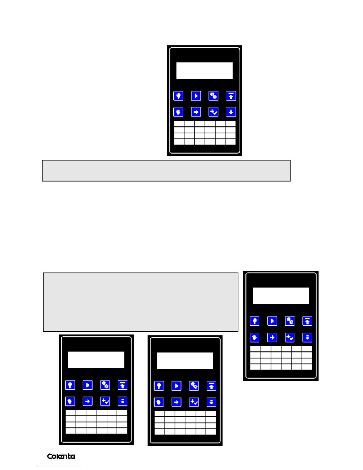
To change the programme, use the following steps:
Press 5one time, you will get:
Start P1 Use
Rep Monitor
NOTE: In case there is a media inside the processor, the display will show you
"Busy processing" - now you need to wait until the current cycle is finished.
To change the program, use
Press
to change the number of the program. P1 wil change to P2, P3, until P8 and
7
to move the cursor to P1.
6
at least PSL (Sleepmode) There are 8 working programs and 1 Sleep program. With
move the cursor to Use and confirm that with
7
.Use
to jump back to the main page.
4
After working (in the evening and through the weekend)
the processor can be set to Sleepmode. This will prevent
cristalization on the rollers.
Start PSL Use
Rep Monitor
Use the above mentioned procedure to do that.
More informations regarding this, see the pages 29,30.
Processor switch off
in 03 sec
Sleep mode!
Run after xxmin
6
,
.... when in Sleep mode.
Page 28
AN 06/2003
page
11.4 AUTOMATIC FUNCTION
24
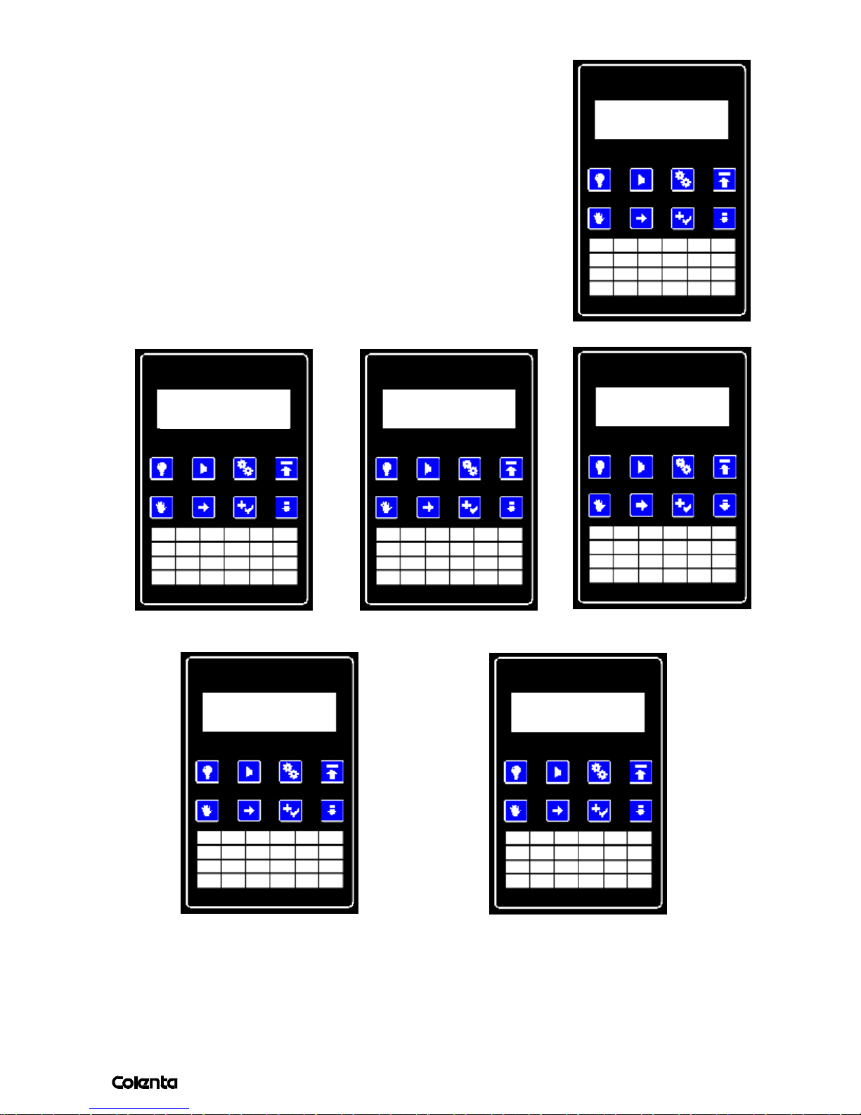
1.
All functions of the processor are totally automatic That means,
during processing, there is no need for the user to change or
to activate something on the display.
The display is used only for to inform and warn the operator
on all functions and working parameters.
To do that, use
. to scroll trough the pages, with
8
you can
4
jump back to the main page, 5 screens are available:
2.
T2: 35.0°C
T3: 45.0°C
3.
Rep1 0300 ml/sqm
Rep2 0350 ml/sqm
4.
P1 xy % done
T1: 35.0°C
Rep3 0300 ml/sqm
4.
Tank1 time 45s
Dry to dry 279s
5.
Speed 108 cm/min
P1 tells you that you are using programe1. In case the processor was started manually
(see page 29), the indication will be M1 instead of P1.
Page 29
AN 06/2003
page
25
xy% Done is the progress indicator. It means xy% of the developing process is complete.
When it reached 100%, the unit will stop the processing mode and will go to standby.
T1=35.0ºC confirms about the actual measured temperature in tank1. The value in the
brackets is the programed temperature. The same indication is valid for:
Tank 2 (T2)........Bleachfix 35°C
Tank 3 (T3)........Dryer 50°C
Rep1, Rep2 and Rep3 are the replenishment rates for the current program for the
corresponding tank. All this values are given by chemistry / film manufacturers.
Tank1 time, is the time when the material is in the developer section in seconds.
Dry to dry is the length of the complete processing cycle (leading edge in to leading edge out).
Speed is the linear speed of the media inside the processor (cm/min).
11.5 Manual Replenishment
It could be necessary to inject fresh chemistry manually by hand. To do that, follow
the procedure underneath:
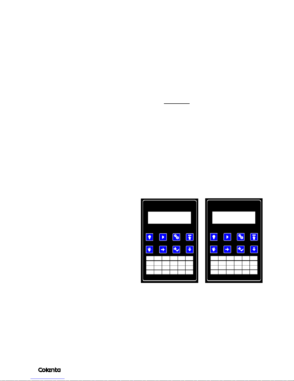
Press
you will see:
To start a replenishment cycle for tank1:
Use
one time, with 6, move the cursor to REP ,confirm that point with 7.
5
Rep1 100 ml ON
Rep2 0 ml OFF
, to move the cursor to REP1 , press 7. one time, this will spent 100ml fresh developer
6
Rep3 100 ml OFF
chemistry to the DEV-tank. To add additional 100ml, press again
The same procedure is valid for Tank 2 and of course to Tank3. Use 6 to jump to REP2 .
With 8 you can scroll trough the next page, in order to start REP3 in same way as described
above. After you finished the manual replenishment, use 4to jump back to the main page.
.and so on......
7
Page 30
AN 06/2003
page
26
11.6 MANUAL START/STOP
The manual start/stop is only possible when no media is in process. During processing
the corresponding menu items cannot be selected.
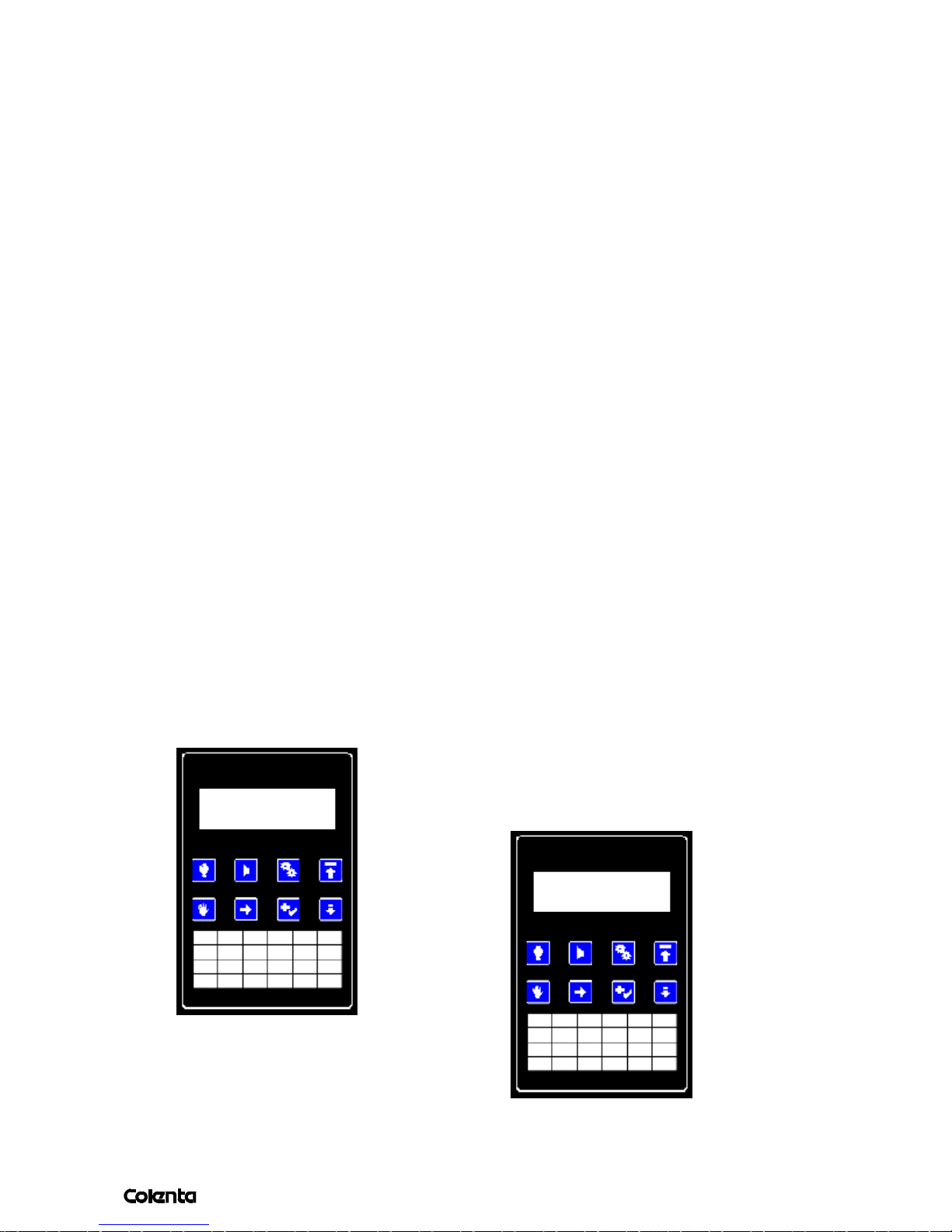
To run the motor manually:
Press
, use 6, move the cursor under Start and confirm with 7.
5
This will start the motor, pumps and dryer unit. The menu item Start will change to
Stop. Stop the motor by confirming Stop again with
7
When the motor was started manually, the display will indicate this on the main page by
showing M1 instead of P1.
11.7 SWITCHING ON/OFF THE DISPLAY ILLUMINATION
In a dark room, it might be necessary to switch off the display backlight to prevent
any exposure on the paper . The 1button toggles the backlight on/off.
When the backlight is off, all the buttons except 1are disabled.
This is necessary to prevent pressing buttons on the panel by mistake in the dark room.
Switching the display off is a good idea when the processor is left unattended. This will reduce the
chances for unauthorized people operating the processor.
11.8 AUTOMATIC START
The processor will start automatically when media is under the sensorbar, except when an
ERROR is active (see list of error messages):
If there is an ERROR,
P1 Film in
the display will show you for
example :
Tank3 too cold
In that case, remove the media from the input section, check the error which is shown,
and feed again.
Page 31
AN 06/2003
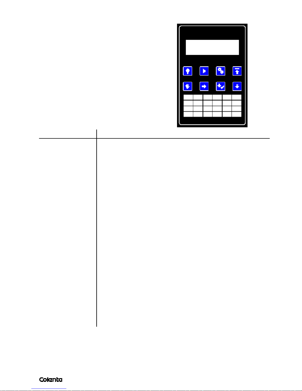
page
11.9 ERROR MESSAGES
If an error occurs, the indication P1 (or M1) will
alternate with Er. If this happens press the 2button.
This will stop the beeper and bring you to the error
menu, so you will be able to check what’s wrong. If
ERROR
more than one error occurred, press
to scan
8
the rest of them.
Press 4to jump back to main page.
Display Reason
Tank1 too cold Temp. Tank1 - 1 °C under the programed value
Tank1 too warm Temp. Tank1 - 1 °C more than the programed value
Tank2 too cold Temp. Tank1 - 1 °C under the programed value
Tank2 too warm Temp. Tank1 - 1 °C more than the programed value
Dryer too warm Temp. Dryer - 5°C too high - call service
Motor overload Failure drive/transport system. The drive motor did not
reach it´s SET-speed - call service
Tank1 low level Level Tank1 (DEV) is too low
Tank2 low level Level Tank2 (BF) is too low
Tank3 low level Level Tank3 (SS1) is too low
Tank4 low level Level Tank4 (SS2) is too low
Tank5 low level Level Tank5 (SS3) is too low
Cover openend Main cover of the processor is open. (Cover switch)
T1: no probe Temperature probe in Tank1 is defect or missing - call service
T2: no probe Temperature probe in Tank2 is defect or missing - call service
T3: no probe Temperature probe in dryer is defect or missing - call service
Rep1 LowLevel Low level in replenishcontainer1 (DEV)
Rep2 LowLevel Low level in replenishcontainer2 (BF)
Rep3 LowLevel Low level in replenishcontainer3 (SS)
Change filter Depending what kind of film / chemistry is in use it might necessary
to use a filter in the circulation. The contoller is equipped with an
incoming film measurement device. That means when a preproamed
m² value of processed film is reached the controller will supply the
message "Change filter" - see next page additional.
Waste 1 high lvl. Waste container 1 (DEV) is full - emty the container
Waste 2 high lvl. Waste container 2 (BF) is full - emty the container
Waste 3 high lvl. Waste container 3 (SS) is full - emty the container
27
Page 32
AN 06/2003
page
28
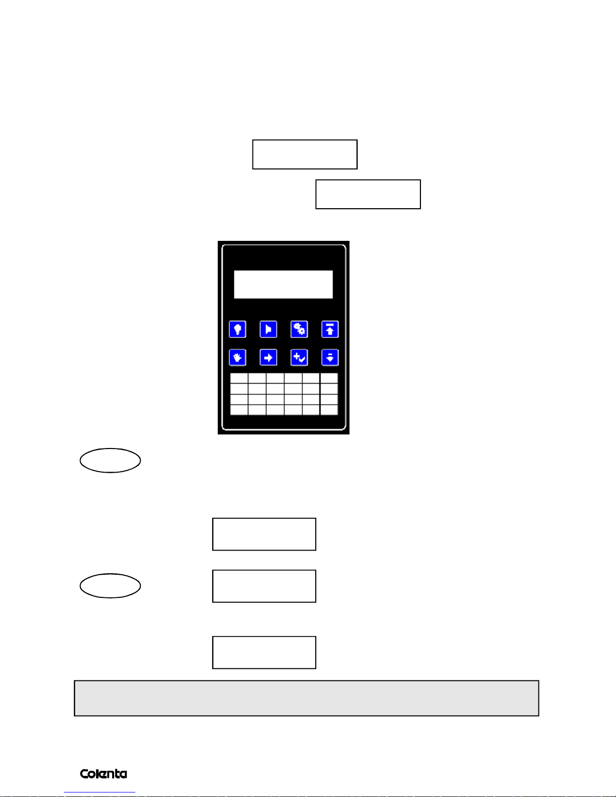
11.10 FILTER CONTROL
The software is equipped with a sub-program to contol the filter - when required.
That means after xxm² processed material, the controller will supply the message
"CHANGE FILTER" - now the filters has to be cleaned / or replaced.
After the filter are new, the counter must be set to zero. To do that, follow the steps
described below:
Press the bottum 3, you will see use6 to move the courser under
Program Setup
Options
"Options", and confirm with 7 , you will get use again 6 to
move the cursor to "Filter", confirm with7 you will see:
Area Log
Standby Filter
Area
The Area menu sets the amount of square meters before filter alert.
The value is 0000-9999 . A value of 0000 turns off the filter alert. (50m²)
Filter alert
after xxxx sqm
Log
The Log menu shows the total processed media area.
After the filter is cleaned, the operator needs to reset the counter to zero. This is
important for confirming the next filter interval.
Save Cancel
0000.00
Exit Clear
Page 33
AN 06/2003
page
29
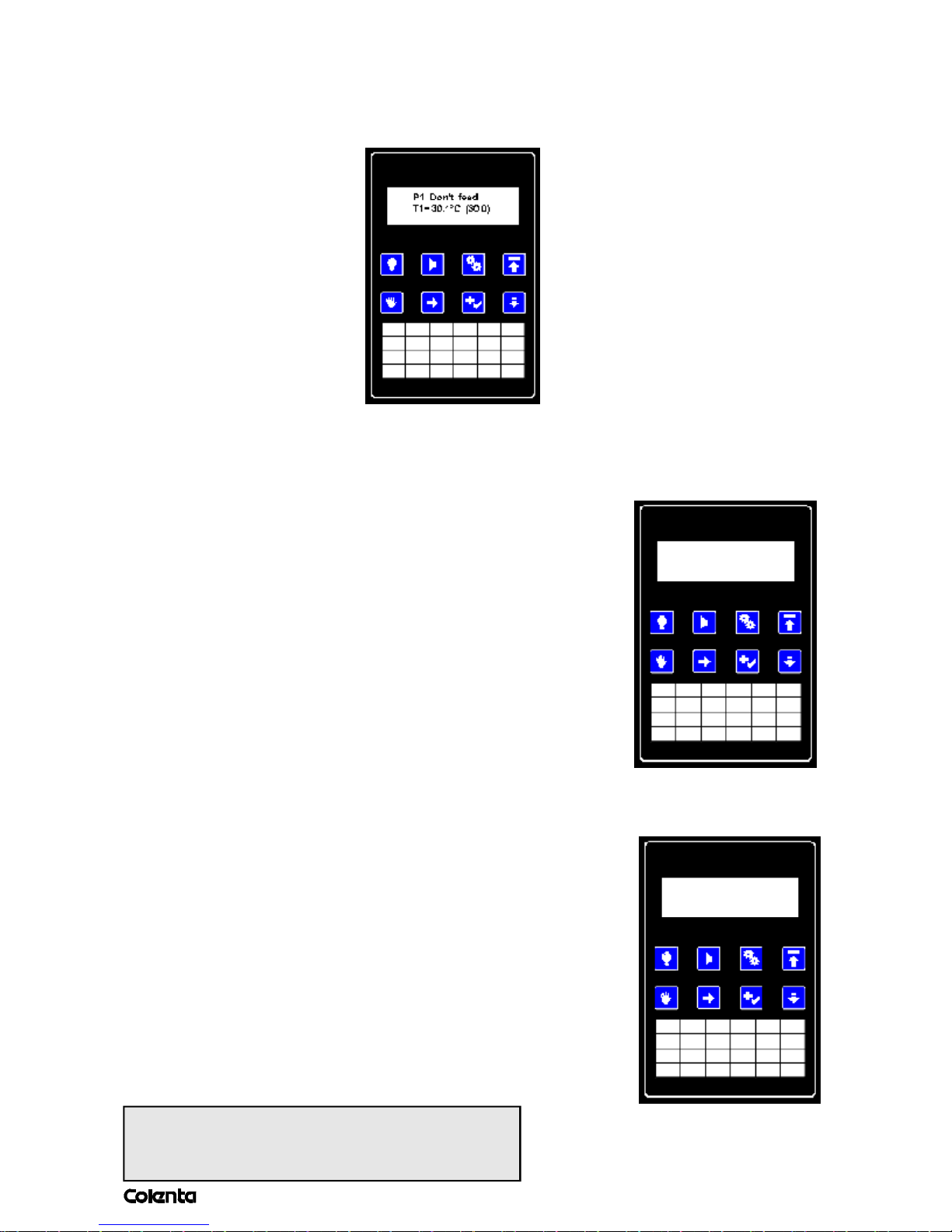
11.11 DISTANCE BETWEEN THE PLATES
To prevent possible transport problems, a minimum distance between the sheets is required.
After the end of the films passes the input section, the display will show:
As long as “Don’t feed” is present , no media should be loaded . After a moment
“Don’t feed” will disappear and a beep will indicate that the input is free again.
11.12 ONLINE INTERFACE
The controller supports online interface. Through the
interface, the processor has to be started before media
arrives at the sensorbar. If the external start is active,
the display will show:
11.13 STANDBY
The processor software contains anti-oxidation and
anti-crystallization modes. That means, when in standby,
the processor will start the transport of the rollers and
the wash-off pump on regular intervals to prevent
crystallization on the rollers (Anti-crystallization). The
anti-oxidation cycle activats at preprogrammable time
intervals to start a replenishment cycle to compensate
oxidation of the the chemistry.
P1 Media coming
T1=35.0°C (35.0)
P1 Cleaning 30%
T1=35.0ºC (35.0)
During such a cleaning cycle, the display
will appear like this:
During this self-cleaning cycle, the processor
will accept media. It's not necessary to wait until
to the end of the cycle.
Page 34
AN 06/2003
page
30
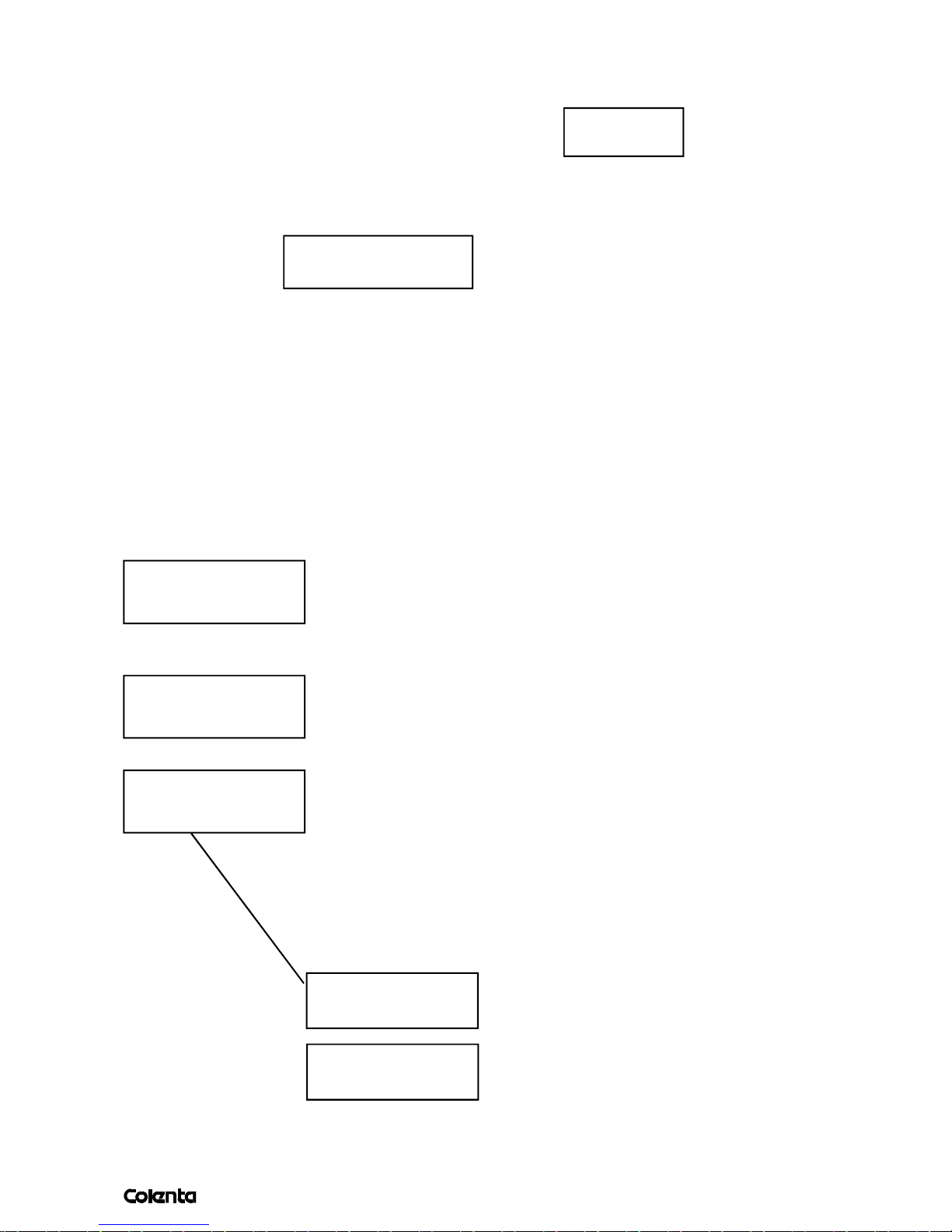
11.14 MONITOR MENUE
The "Monitor Programme" is used to check and calibrate several important parameters
within the processor. Press the bottum 5, you will see: , move the cursor by
using 6 to Monitor and confirm with
the first page looks like this:
7
Start P1 Use
Rep Monitor
DDBFS1S2S3DD
--------
This represents the processor,: the first two DD represent the Developer section, BF the Bleachfix , S1 - the Superstabi1, S2 - the Superstabi2, S3 - the Superstabi3 and the last
DD is the dryer section.
The dashes on the second row indicate the position of the material.
The following indications are:
Motor Off / On Motor is On or Off
Speed 42 024 19 speed
001 pulse confirming from the motor tacho
Normal s-bar Type of sensorbar
Area=0.0000 sqm. Displays the film area entering the processor
S-bar: --------- This feature is used to check each sensor of
----------- the sensor-bar. The COLENTA 56 RA-7MW is
equipped with 6 sensors. To check the sensors, use
the following instructions:
-put a small film under the sensorbar (don’t feed into the
processor)
-move the film accros the witdth of the sensorbar
-at the same time have a look to the display
S-bar: ---------
---------10
That means sensor 1 and 0 are occupied
and so on......
S-bar: ---------
-------32--
That means sensor 3 and 2 are occupied
Page 35
AN 06/2003
page
31
........as described before:
piece of material
sensorbar
sensor:
5 4 3 2 1 0
input table
H1=0 H2=0 H3=1 H1=1 or 0 Heating Developer On or OFF
Fan=0 S1=0 S2=0
H2=1 or 0 Heating BF On or OFF
H3=1 or 0 Heating DRY On or OFF
Fan=1 or 0 Fan for the Dryer On or OFF
S1=1 or 0 Valve 1 Cooling On or OFF
Option for Wash!
S2=1 or 0 Valve 2 Cooling On or OFF
Rep1=1 or 0 Replenisher pump 1 On or OFF
Rep1=0 Rep2=0
Rep3=0
Rep2=1 or 0 Replenisher pump 2 On or OFF
Rep3=1 or 0 Replenisher pump 3 On or OFF
11.15 HOW TO EXIT THE MONITORMODE
To leave the sleep mode, push 1 1 time to switch on the display illumination, use
7 to put the processor back to work mode.
Page 36
AN 06/2003
page
12.MAINTENANCE
32
The processor is designed to produce consistent high quality production with the minimum
of maintenance.
Regular maintenance minimizes the chances for equipment failure and loss of
processing quality. A well trained person has to be responsible for performing the maintenance
of the processor and must be familiar with the operation and function of it as well.
1. Daily maintenance
*) Check levels of the external replenishmener tanks -
If necessary mix fresh solution.
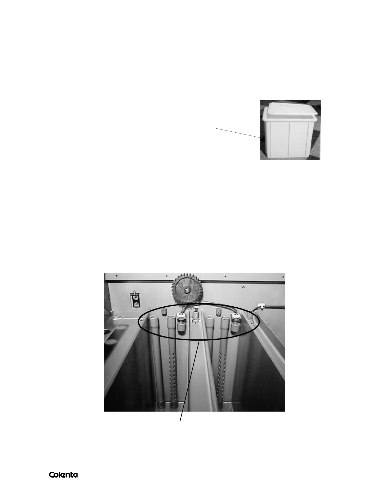
*) Cleaning feed tray.
*) Cleaning spray-bar-guide for the fixer
*) Before starting production we advise to feed some cleaning films to remove any
overnight residue.
2. Weekly maintenance
*) Wipe external surfaces of film processor / enclosures / panels
with a wet cloth to remove any chemical / dirt deposits.
*) Inspect and clean the wash tank and intermediate water rins drains. If algaes present
then the should be removed, in such a case we suggest to use a proven algae control
system -
*) Have a look to the above shown drainpipes / overflow tubes - remove any deposites
to prevent a blockad of the drain.
Page 37

AN 06/2003
page
13.RECOMMENDED MAINTENANCE EVERY 3-6
33
MONTHS.
(Period is subject to processor useage.)
Good processing quality and the reliable operation of a processor is dependent upon regular and
careful cleaning. Every 3-6 months, the chemicals in the tanks should be drained.
A chemical cleaning of the processing tanks and wash tank is recommended. Always follow
safety warnings as described in section 1 when cleaning the processor.
Prior to carrying out any maintenance, switch off the power at the main power switch
(position "0") ensuring it cannot beaccidently switched back on.
*) Switch off the main power switch of the processor first (position „0“).
*) Remove the top cover of the processor.
*) Drain individual tanks by open the draintaps in front of the processor.
*) Remove rack assemblies ( DEV / BX / SST, see item 2.1) and put them aside.
*) Close taps and fill all tanks with water or better with suitable cleaning solution
until the red mark inside the tanks are reached.
*) Put the racks back into the tanks of the processor and close the top cover.
*) Switch on the processor and start some replenishment cycles. The hoses will be
cleaned with water as well. Also start the transport of the filmprocessor, the racks have to
be in. Let the processor run for 10 to 15 minutes.
*) Switch off („0“ position)the main power switch of the filmprocessor and drain the
processor tanks again.
*) NOTE: Use cleaning solution according to the manufacturer´s instructions.
*) After tank cleaning, the developer- and wash-tank should be filled twice with fresh water
(eventually use neutralizer recommended by manutacturer). Let the processor run for
approximately 10 minutes again. Check all external (outside of the processor)
hose connectors (outside of filmprocessor) and fittings for leaks.
*) Drain all tanks.
*) Remove the water / DEV / BX / SST Racks and check for:
-worn gears
-damaged or worn bearings
-loose screws
-scratched or bent film guides
-plastic flat springs in developer bottom underturn.
*) All repairs must be carried out by qualified service personnel.
*) Check the inside of the tank for contamination and alien substances.
*) Clean the rollers well.
*) Close the drain taps of all 3 tanks.
*) Fill developer, bleachfix and SST tanks with fresh chemicals to the required level (1st SST,
2nd bleachfix and 3rd developer)
*) Re-install the racks carefully. Take care of correct sequence of the racks is followed and
make sure the gears are in the right position. Secure the racks.
*) Insert the respective suction pipe to the correct external replenisher tank.
Re-install the top cover and switch on the processor.
*) Process test strips.
Page 38

AN 06/2003
page
34
14. SAFETY INSTRUCTIONS
13.1 PERFORMING AN EMERGENCY STOP
You may need to stop processing immediately because:
- there is risk of personal injury.
- material is jammed or is loaded incorrectly
No special emergency stop button has been provided. Therefore, the main switch also functions
as an emergency stop
You have two ways of performing an emergency stop:
- simply switch off the processor using the main switch (See below)
- deactivate the processor by opening one of the covers.
13.2 HANDLING INSTRUCTIONS CONCERNING CHEMICALS
1 - Splashing danger during mixing the chemistry
- Always wear glasses or safety goggles to protect your eyes against the splashing of
chemicals.
- Always wear glasses and gloves when handling chemicals or while working in the
chemical section of the processor.
- if your eyes come into contact with chemical, rinse immediately with clean cold water
– if your eyes become sore, seek immediate medical attention.
- If your skin comes into contact with chemicals, wash contact points with lots of clean, cold
running water.
2 - Chemicals and Safety Data Sheets (SDS)
Take into account the following safety measures and recommendations before
handling chemicals:
- Consult the appropriate Safety Data Sheets (SDS) before handling chemicals.
- The operator has to take care that the correct chemicals are in use.
Page 39

AN 06/2003
page
35
3 - How to obtain SDS
Your local Chemistry sales company will on request send you Safety Data Sheets. Read them
very carefully and keep with this Manual.
4 - SDS contents
- Emergency telephone No. - Exposure control and personal protection
- Composition of Chemicals - Physical and chemical properties
- Hazards identification - Information on stability and reactivity
- First-Aid measures - Toxicological information
- Fire-fighting measures - Ecological information
- Accidental release measures - Disposal information
- Handling and storage - Transport information
- Regulatory information.
5 - Avoiding personal injuries
Take into account the safety measures listed below to avoid injuries when and after
handling chemicals:
- Do not exaggerate the use of chemicals or water in order to avoid trays from overflowing.
- Do not drain chemicals into public sewage systems without checking local regulations.
- Never blend chemicals in one tank, unless stated otherwise.
- Always follow the instructions on the label of the tank.
- Always wear glasses or safety goggles to protect your eyes against the splashing of
chemicals.
- Always wear glasses and gloves when handling chemicals or while working in the
chemical section of the processor.
- If your eyes come into contact with chemicals, rinse them with clean, cold running
water. If your eyes are irritated, immediately seek medical attention.
- If your skin comes into contact with chemicals, wash immediately with clean, cold
running water.
- Avoid inhaling chemical vapours. Provide adequate ventilation in order to keep
airborne concentrations well below occupational exposure limits to prevent any
discomfort in the workplace. Direct exhaust vents to the outside of the building.
Page 40

 Loading...