

Page 1
USER°S INFORMATION,
MAINTENANCE AND
SERVICE
HIGH EFFiCiENCY
TUBULAR HEAT EXCHANGER SERIES
MODELS_ UGAD / UGAE / UGAF
(S_ngleoS_ag÷ UpHow, 92% AFUE,
Manufactured Housin9 or Modular Home Applications)
ISO 9001
Certified Quality
Management System
CONTACT INFORMATION FOR USA ....................... 1
CONTACT INFORMATION FOR CANADA ................... 1
USER'S INFORMATION ................................... 1
SAFETY .............................................. 1
INSTRUCTIONS FOR EXAMINING THE
FURNACE INSTALLATION ............................... 2
HOW YOUR GAS FURNACE WORKS ...................... 3
START-UP AND SHUTDOWN INSTRUCTIONS ............... 3
Read the Instructions Below Before Trying to Start the Furnace.. 3
Operating Instructions: .................................. 3
To Turn Off the Appliance: ............................... 3
FURNACE USER MAINTENANCE .......................... 3
Air Filters ............................................ 4
Replacing Filters ...................................... 4
How to Clean your Filter ................................ 4
Blower Care .......................................... 4
Motor Lubrication ...................................... 4
SERVICE AND MAINTENANCE MANUAL ..................... 5
TABLE
CONTACT INFORMATION FOR USA
• Contact usby mail:
DISTRIBUTED BY:
StyleCrest
801 W. 37th Street
Building #7
Wichita, Ks 67219
MANUFACTURED BY:
York International
5005 York Drive
Norman, OK 73069
The manufacturer recommends that the user read all sec-
tions of this manual and keep the manual for future refer-
ence.
AWARNING
FIRE OR EXPLOSION HAZARD - Failure to follow
safety warnings exactly could result in serious injury,
death, or property damage.
m Do not store or use gasoline or other flammable
vapors and liquids in the vicinity of this or any
other appliance.
WHAT TO DO IF YOU SMELL GAS:
• Do not try to light any appliance.
• Do not touch any electrical switch; do not use any
phone (included cell phone) in your building.
• Leave the building immediately.
• Immediately call your gas supplier from a neighbor's
phone. Follow the gas supplier's instructions.
• If you cannot reach your gas supplier, call the fire
department.
-- Installation and service must be performed by a
qualified installer, service agency or the gas sup-
plier.
OF CONTENTS
SAFETY SECTION ...................................... 5
FURNACE MAINTENANCE SECTION ....................... 5
FURNACE CLEANING SECTION ........................... 5
Burner Removal/Cleaning ............................... 5
Cleaning the Heat Exchanger ............................ 5
Cleaning the Secondary Heat Exchanger ................... 5
TROUBLESHOOTING ................................... 5
SEQUENCE OF OPERATION ............................. 5
Continuous Blower ..................................... 5
Intermittent Blower - Cooling ............................. 6
Heating Cycle ......................................... 6
Hot Surface Ignition System .............................. 6
FURNACE CONTROL DIAGNOSTICS ....................... 6
DIAGNOSTIC FAULT CODE STORAGE AND RETRIEVAL ...... 7
REPLACEMENT PARTS LIST .............................. 8
REPLACEMENT PART CONTACT INFORMATION ........... 10
WIRING DIAGRAM ...................................... 11
LIMITED WARRANTY .................................... 12
CONTACT INFORMATION FOR CANADA
Go to website at www.york.com click on "contact", then click on
"contact form" and follow the instructions.
Contact us by mail:
York International
Consumer Relations
5005 York Drive
Norman, OK 73069
SECTION h USER'S INFORMATION
SAFETY
1. The furnace area must be kept clear and free of combustible mate-
rials, gasoline and other flammable vapors and liquids.
2. Insulating materials may be combustible. The furnace must be
kept free and clear of insulating materials. The furnace area must
be examined when installed in an attic or other insulated space or
when insulation is added to be sure that the insulation material has
been kept away from the furnace.
3. The furnace needs air for combustion in order to operate properly
and safely. Do not block or obstruct air openings on the furnace,
air openings to the area where the furnace is installed, or spaces
around the furnace.
4. Follow the instructions exactly as shown on the OPERATING
INSTRUCTION LABEL or the Start-up and Shutdown Instructions
on Page 3 of this manual when lighting the furnace or turning the
furnace off.
5. Should the gas supply fail to shut off or if overheating occurs, shut
off the gas valve to the furnace before shutting off the electrical
supply.
6. Do not use this furnace if any part has been under water. A flood-
damaged furnace is extremely dangerous. Attempts to use the fur-
nace can result in fire or explosion. A qualified service agency
should be contacted to inspect the furnace and replace all gas
controls, control system parts, electrical parts that have been wet
or the furnace if deemed necessary.
268897-UUM-B-1108
Page 2
268897-UUM-B-1108
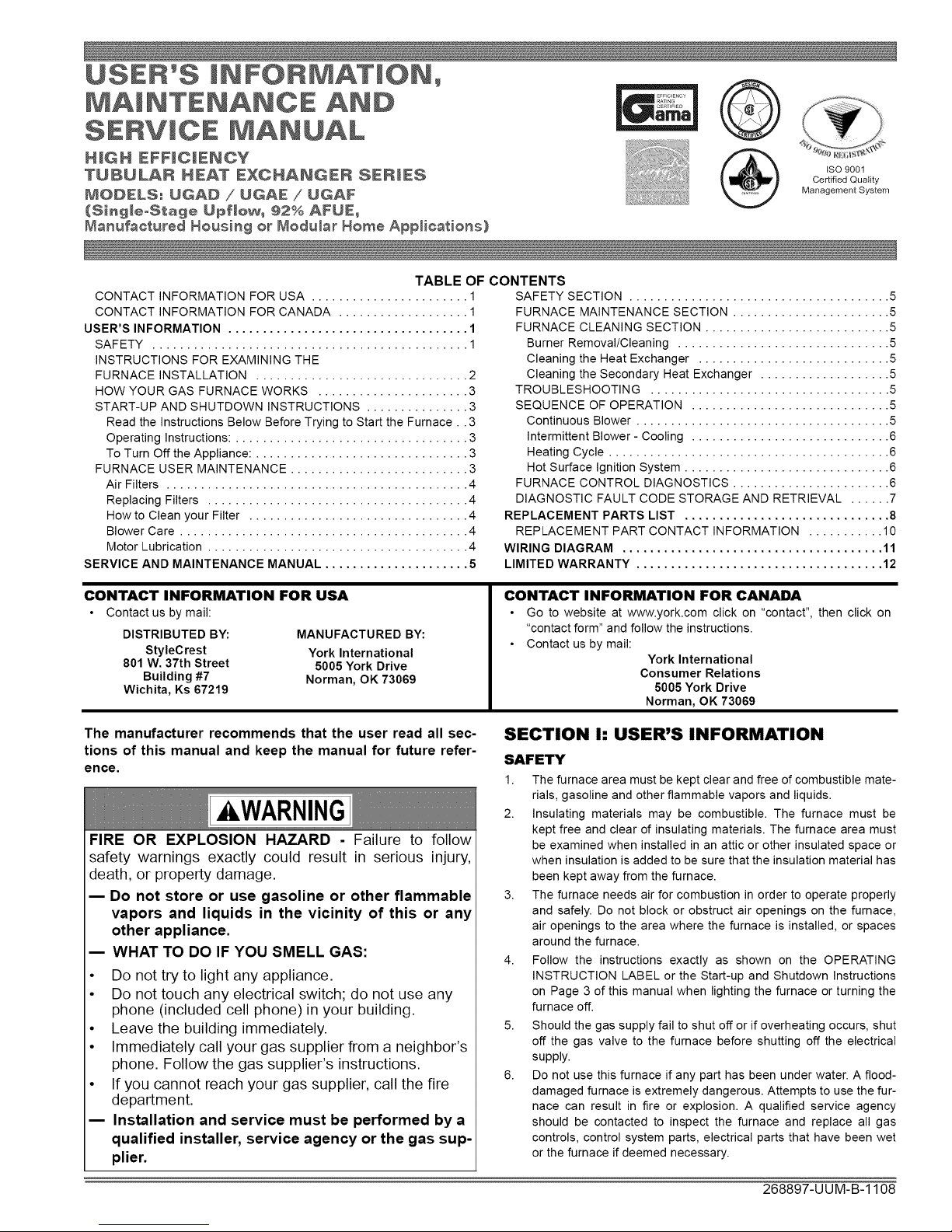
BURNER
BOX
LIMIT
-- GAS VALVE
PRESSURE
SWITCH
DOOR
SWITCH
FIGURE 1: Component Locations
7. NEVER...Store flammable materials of any kind near your fur-
nace. Gasoline, solvents, and other volatile liquids should be
stored only in approved containers outside your home. These
materials vaporize easily and are extremely dangerous.
8. NEVER...Store cleaning materials near your furnace. Materials
such as bleaches, detergents, powdered cleansers, etc., can
cause corrosion of the heat exchangers.
9. NEVER... Use the area around your furnace as a storage area
for items which could block the normal flow of air. This flow of air is
required for ventilation of the various furnace components.
FIRE OR EXPLOSION HAZARD
This furnace is designed and approved for use with Nat-
ural Gas and (LP) Propane Gas ONLY. DO NOT BURN
ANY LIQUID FUEL OR SOLID FUEL IN THIS FURNACE.
Burning any unapproved fuel will result in damage to the
furnace heat exchanger, which could result in Fire, Per-
sonal Injury, and/or Property Damage.
PIPE
INDUCER
BLOWER
CONDENSATE
TRAP
CONTROL
BOARD
INSTRUCTIONS FOR EXAMINING THE FURNACE
INSTALLATION
It is the owner's responsibility to ensure that an annual inspection of the
entire heating portion of the unit is made by a qualified service agency.
1. Examine the heat exchanger, vent/combustion air piping, vent
connectors and chimney to be sure they are clear and free of
obstructions.
2. Examine the vent pipe making sure it is firmly in place, that it
slopes slightly upward and is physically sound without holes and
all of the connections are secure.
3. Examine return connections
For Modular Homes:
a. If the furnace has a return air duct, examine the return air
duct connections to make sure they are physically sound,
sealed to the furnace casing, and the ducts terminate out-
side the space containing the furnace.
b. If the furnace does not have a return air duct, examine the
return air filter rack connections to make sure they are phys-
ically sound, sealed to the furnace casing.
For Manufactured (Mobile) Homes:
a. Examine the return air filter rack connections to make sure
they are physically sound, sealed to the furnace casing.
4. Examine the furnace casing making sure the physical support is
sound without sagging, cracks or gaps. Examine the furnace base
making sure it is physically sound without cracks, gaps or sagging
and has a good seal.
5. Examine the furnace casing for obvious signs of deterioration.
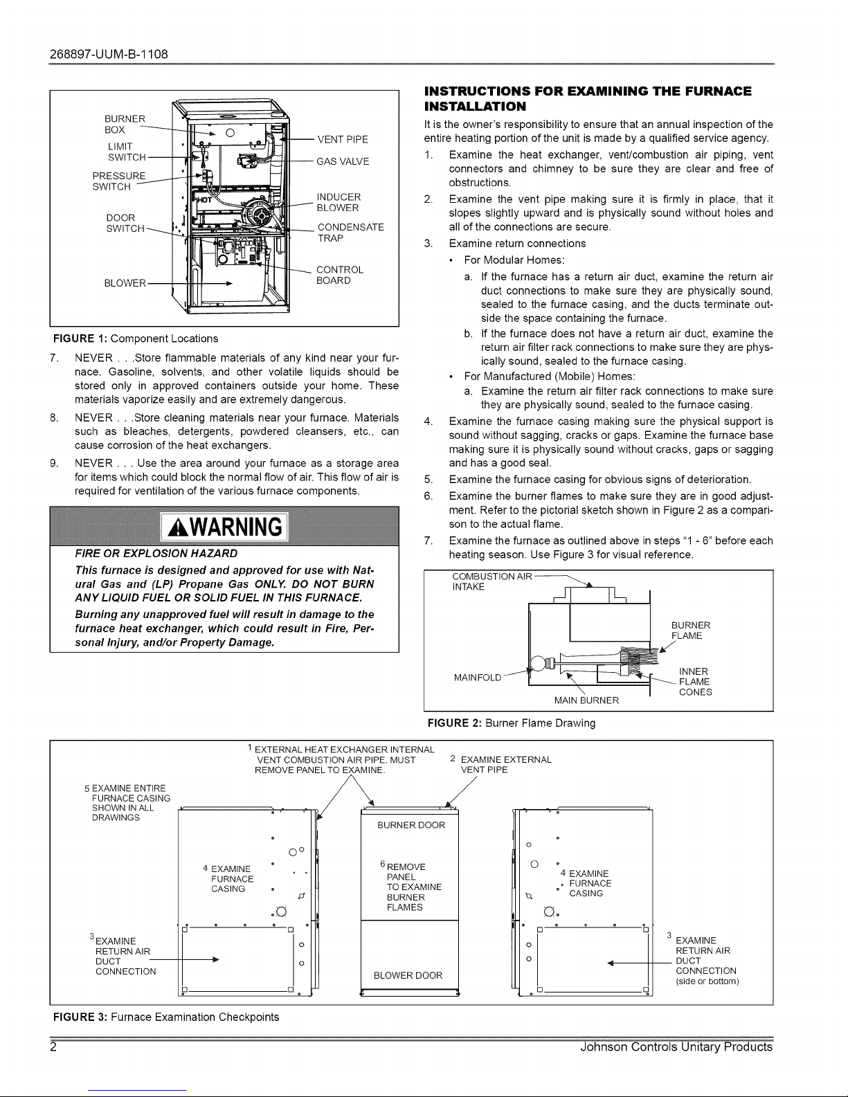
6. Examine the burner flames to make sure they are in good adjust-
ment. Refer to the pictorial sketch shown in Figure 2 as a compari-
son to the actual flame.
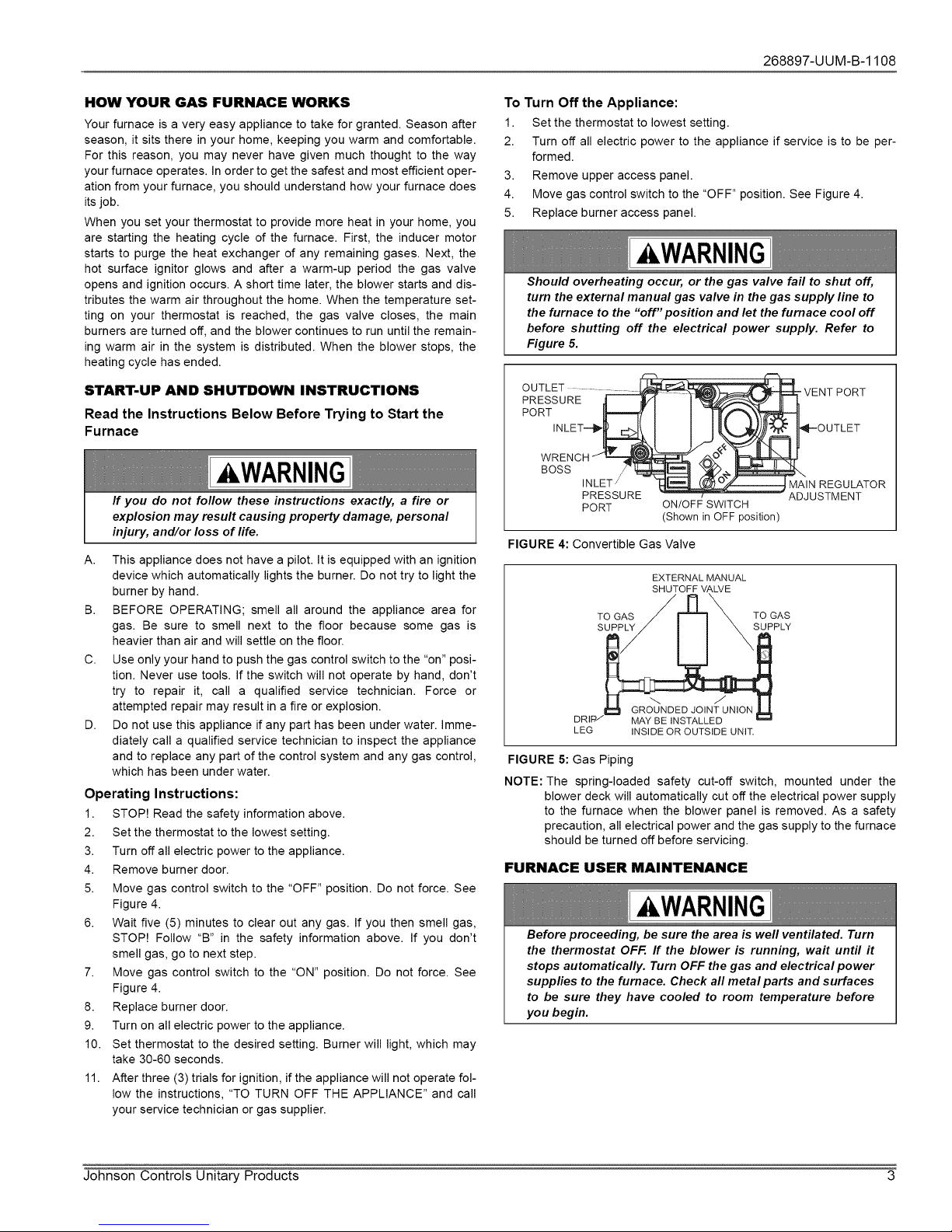
7. Examine the furnace as outlined above in steps "1 - 6" before each
heating season. Use Figure 3 for visual reference.
COMBUSTIONAIR_ •
INTAKE _1
BURNER
I I FLAME
MA,NFOLDJ
\ I CONES
MAIN BURNER
FIGURE 2: Burner Flame Drawing
1 EXTERNAL HEAT EXCHANGER INTERNAL
VENT COMBUSTION AIR PIPE. MUST
REMOVE PANEL TO EXAMINE. VENT PiPE
5EXAMINE ENTIRE
FURNACE CASING
SHOWNINALL
DRAWINGS
3EXAMINE
RETURN AIR
DUCT
CONNECTION
4 EXAMINE
FURNACE
CASING
O o
o©
[]
o
o
[] o
,,_ , ,,_
BURNERDOOR
6REMOVE
PANEL
TO EXAMINE
BURNER
FLAMES
BLOWER DOOR
FIGURE 3: Furnace ExaminationCheckpoints
2 Johnson Controls Unitary Products
2 EXAMINE EXTERNAL
•. ..;
0 o
o <
°[
oD
Q©
4 EXAMINE
,, FURNACE
CASING
b
q
3
EXAMINE
RETURN AIR
DUCT
CONNECTION
(side or bottom)
Page 3
268897-UUM-B-1108
HOW YOUR GAS FURNACE WORKS
Your furnace is a very easy appliance to take for granted. Season after
season, it sits there in your home, keeping you warm and comfortable.
For this reason, you may never have given much thought to the way
your furnace operates. In order to get the safest and most efficient oper-
ation from your furnace, you should understand how your furnace does
its job.
When you set your thermostat to provide more heat in your home, you
are starting the heating cycle of the furnace. First, the inducer motor
starts to purge the heat exchanger of any remaining gases. Next, the
hot surface ignitor glows and after a warm-up period the gas valve
opens and ignition occurs. A short time later, the blower starts and dis-
tributes the warm air throughout the home. When the temperature set-
ting on your thermostat is reached, the gas valve closes, the main
burners are turned off, and the blower continues to run until the remain-
ing warm air in the system is distributed. When the blower stops, the
heating cycle has ended.
START-UP AND SHUTDOWN INSTRUCTIONS
Read the Instructions Below Before Trying to Start the
Furnace
AWARNING
If you do not follow these instructions exactly, a fire or
explosion may result causing property damage, personal
injury, and/or loss of life.
A. This appliance does not have a pilot. It is equipped with an ignition
device which automatically lights the burner. Do not try to light the
burner by hand.
B. BEFORE OPERATING; smell all around the appliance area for
gas. Be sure to smell next to the floor because some gas is
heavier than air and will settle on the floor.
C. Use only your hand to push the gas control switch to the "on" posi-
tion. Never use tools. If the switch will not operate by hand, don't
try to repair it, call a qualified service technician. Force or
attempted repair may result in a fire or explosion.
D. Do not use this appliance if any part has been under water. Imme-
diately call a qualified service technician to inspect the appliance
and to replace any part of the control system and any gas control,
which has been under water.
Operating Instructions:
1. STOP! Read the safety information above.
2. Set the thermostat to the lowest setting.
3. Turn off all electric power to the appliance.
4. Remove burner door.
5. Move gas control switch to the "OFF" position. Do not force. See
Figure 4.
6. Wait five (5) minutes to clear out any gas. If you then smell gas,
STOP! Follow "B" in the safety information above. If you don't
smell gas, go to next step.
7. Move gas control switch to the "ON" position. Do not force. See
Figure 4.
8. Replace burner door.
9. Turn on all electric power to the appliance.
10. Set thermostat to the desired setting. Burner will light, which may
take 30-60 seconds.
11. After three (3) trials for ignition, if the appliance will not operate fol-
low the instructions, "TO TURN OFF THE APPLIANCE" and call
your service technician or gas supplier.
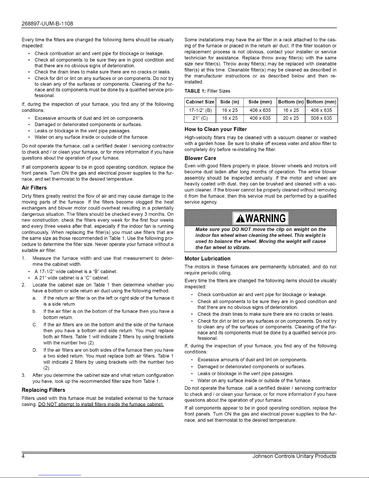
To Turn Off the Appliance:
1. Set the thermostat to lowest setting.
2. Turn off all electric power to the appliance if service is to be per-
formed.
3. Remove upper access panel.
4. Move gas control switch to the "OFF" position. See Figure 4.
5. Replace burner access panel.
WARNING
Should overheating occur, or the gas valve fail to shut off,
turn the external manual gas valve in the gas supply line to
the furnace to the "off"position and let the furnace cool off
before shutting off the electrical power supply. Refer to
Figure 5.
OUTLET ......... _'1_
ENT PORT
PRES_U::T__.__ _
INLET/
PRESSURE
PORT
FIGURE 4: Convertible Gas Valve
EXTERNAL MANUAL
SHUTOFF VALVE
TOGAS F =[_'_ TOGAS
DRIPI_ PLY
LEG INSIDE OR OUTSIDE UNIT.
FIGURE 5: Gas Piping
NOTE: The spring-loaded safety cut-off switch, mounted under the
blower deck will automatically cut off the electrical power supply
to the furnace when the blower panel is removed. As a safety
precaution, all electrical power and the gas supply to the furnace
should be turned off before servicing.
_IN REGULATOR
ON/OFF SWITCH
(Shown in OFF position)
FURNACE USER MAINTENANCE
AWARNING
Before proceeding, be sure the area is well ventilated. Turn
the thermostat OFF. ff the blower is running, wait until it
stops automatically. Turn OFF the gas and electrical power
supplies to the furnace. Check all metal parts and surfaces
to be sure they have cooled to room temperature before
you begin.
OUTLET
ADJUSTMENT
Johnson Controls Unitary Products 3
Page 4
268897-UUM-B-1108
Every time the filters are changed the following items should be visually
inspected:
Check combustion air and vent pipe for blockage or leakage.
Check all components to be sure they are in good condition and
that there are no obvious signs of deterioration.
Check the drain lines to make sure there are no cracks or leaks.
Check for dirt or lint on any surfaces or on components. Do not try
to clean any of the surfaces or components. Cleaning of the fur-
nace and its components must be done by a qualified service pro-
fessional.
If, during the inspection of your furnace, you find any of the following
conditions:
Excessive amounts of dust and lint on components.
Damaged or deteriorated components or surfaces.
Leaks or blockage in the vent pipe passages.
Water on any surface inside or outside of the furnace.
Do not operate the furnace, call a certified dealer / servicing contractor
to check and / or clean your furnace, or for more information if you have
questions about the operation of your furnace.
If all components appear to be in good operating condition, replace the
front panels. Turn ON the gas and electrical power supplies to the fur-
nace, and set thermostat to the desired temperature.
Air Filters
Dirty filters greatly restrict the flow of air and may cause damage to the
moving parts of the furnace. If the filters become clogged the heat
exchangers and blower motor could overheat resulting in a potentially
dangerous situation. The filters should be checked every 3 months. On
new construction, check the filters every week for the first four weeks
and every three weeks after that, especially if the indoor fan is running
continuously. When replacing the filter(s) you must use filters that are
the same size as those recommended in Table 1. Use the following pro-
cedure to determine the filter size. Never operate your furnace without a
suitable air filter.
1. Measure the furnace width and use that measurement to deter-
mine the cabinet width.
• A 17-1/2" wide cabinet is a "B" cabinet.
• A 21" wide cabinet is a "C" cabinet.
2. Locate the cabinet size on Table 1 then determine whether you
have a bottom or side return air duct using the following method.
a. If the return air filter is on the left or right side of the furnace it
is a side return
b. If the air filter is on the bottom of the furnace then you have a
bottom return.
C. If the air filters are on the bottom and the side of the furnace
then you have a bottom and side return. You must replace
both air filters. Table 1 will indicate 2 filters by using brackets
with the number two (2).
D. If the air filters are on both sides of the furnace then you have
a two sided return. You must replace both air filters. Table 1
will indicate 2 filters by using brackets with the number two
(2).
3. After you determine the cabinet size and what return configuration
you have, look up the recommended filter size from Table 1.
Replacing Filters
Filters used with this furnace must be installed external to the furnace
casinq DO NOT attempt to install filters inside the furnace cabinet.
Some installations may have the air filter in a rack attached to the cas-
ing of the furnace or placed in the return air duct. If the filter location or
replacement process is not obvious, contact your installer or service
technician for assistance. Replace throw away filter(s) with the same
size new filter(s). Throw away filter(s) may be replaced with cleanable
filter(s) at this time. Cleanable filter(s) may be cleaned as described in
the manufacturer instructions or as described below and then re-
installed.
TABLE 1: Filter Sizes
Cabinet Size Side (in) Side (mm) Bottom (in) Bottom (mm)
17-1/2" (B) 16 x 25 406 x 635 16 x 25 406 x 635
21" (C) 16x25 406 x 635 20x25 508 x 635
How to Clean your Filter
High-velocity filters may be cleaned with a vacuum cleaner or washed
with a garden hose. Be sure to shake off excess water and allow filter to
completely dry before re-installing the filter.
Blower Care
Even with good filters properly in place, blower wheels and motors will
become dust laden after long months of operation. The entire blower
assembly should be inspected annually. If the motor and wheel are
heavily coated with dust, they can be brushed and cleaned with a vac-
uum cleaner. If the blower cannot be properly cleaned without removing
it from the furnace, then this service must be performed by a qualified
service agency.
kWARNING
Make sure you DO NOT move the clip on weight on the
indoor fan wheel when cleaning the wheel. This weight is
used to balance the wheel. Moving the weight will cause
the fan wheel to vibrate.
Motor Lubrication
The motors in these furnaces are permanently lubricated, and do not
require periodic oiling.
Every time the filters are changed the following items should be visually
inspected:
• Check combustion air and vent pipe for blockage or leakage.
• Check all components to be sure they are in good condition and
that there are no obvious signs of deterioration.
• Check the drain lines to make sure there are no cracks or leaks.
• Check for dirt or lint on any surfaces or on components. Do not try
to clean any of the surfaces or components. Cleaning of the fur-
nace and its components must be done by a qualified service pro-
fessional.
If, during the inspection of your furnace, you find any of the following
conditions:
Excessive amounts of dust and lint on components.
Damaged or deteriorated components or surfaces.
Leaks or blockage in the vent pipe passages.
• Water on any surface inside or outside of the furnace.
Do not operate the furnace, call a certified dealer / servicing contractor
to check and / or clean your furnace, or for more information if you have
questions about the operation of your furnace.
If all components appear to be in good operating condition, replace the
front panels. Turn ON the gas and electrical power supplies to the fur-
nace, and set thermostat to the desired temperature.
4 Johnson Controls Unitary Products
Page 5

268897-UUM-B-1108
SECTION Ih SERVICE AND MAINTENANCE
MANUAL
SAFETY SECTION
The following safety rules must be followed when servicing the
furnace.
,WARNING
ELECTRIC SHOCK, FIRE OR EXPLOSION HAZARD
Failure to follow safety warnings exactly could result in
dangerous operation, serious injury, death or property
damage.
Improper servicing could result in dangerous operation,
serious injury, and death or property damage.
Before servicing, disconnect all electrical power to the fur-
Race.
When servicing controls, label all wires prior to disconnect-
ing. Reconnect wires correctly.
Verify proper operation after servicing.
FURNACE MAINTENANCE SECTION
The furnace should be cleaned and adjusted by a certified dealer or
qualified service contractor once a year or before the start of every
heating season. The following items must be cleaned and serviced or
replaced if there are signs of deterioration.
1. The vent terminal.
2. The furnace vent and combustion air intake passageways. Should
it be necessary to service the vent/air intake system, the manufac-
turer recommends this service be conducted by a qualified service
agency. The operation of this appliance requires the reassembly
and resealing of the vent/air intake system.
3. The furnace burners, ignitor and flame sensor.
4. The condensate collection and disposal system. If any disassem-
bly of components containing flue or vent gases is required, a
qualified service agency must perform the service.
FURNACE CLEANING SECTION
NOTE: The cleaning operations listed below must be performed only by
a qualified service agency.
Burner Removal/Cleaning
The main burners should be checked periodically for dirt accumulation.
If cleaning is required, follow this procedure:
1. Turn off the electrical power to the unit.
2. Turn off the gas supply at the external manual shut-off valve and
loosen the ground union joint.
3. Remove the burner door and remove the burner box cover.
4. Disconnect wires from flame sensor, rollout switch and HSI igniter.
Remove igniter carefully, as it is easily broken.
5. Remove the screws that hold the burner box assembly to the vest
panel and remove the assembly.
6. Remove burners from the burner assembly.
7. Burners may be cleaned by rinsing in hot water.
8. Reassemble the burners in the reverse order.
Cleaning the Heat Exchanger
1. Turn off the electrical power to the unit.
2. Turn off the gas supply at the external manual shut-off valve and
loosen the ground union joint.
3. Remove the burner door and remove the burner box cover.
4. Disconnect wires from flame sensor, rollout switch and HSI igniter.
Remove igniter carefully, as it is easily broken.
5. Remove the screws that hold the burner box assembly to the vest
panel and remove the assembly.
6. Remove the vent pipe assembly, vent blower and condensate pan.
7. The heat exchanger is now exposed.
8. With a long flexible wire brush, clean inside each tube at both the
top and bottom. The brush must pass around the rear heat
exchanger tubes. Then vacuum loose the scale and dirt from each
tube.
9. Replace all components in reverse order. Reconnect all wiring.
10. Restore electrical power and gas supply to the furnace.
11. Check furnace operation.
CAUTION
Label all wires prior to disconnection when servicing
controls. Wiring errors can cause improper and danger-
ous operation. Verify proper operation after servicing.
Cleaning the Secondary Heat Exchanger
1. Follow steps 1 - 7 under cleaning the Heat Exchanger.
2. Remove the vent piping from the vent blower housing. Disconnect
the drain lines from the vent blower housing and from the conden-
sate drain pan. Remove the vent blower housing blower and the
condensate pan.
3. Using a stiff wire brush, remove the loose scale or soot from each
tube.
4. Vacuum the secondary heat exchanger.
5. Finish the cleaning procedure by following steps 9 - 11 under
cleaning the Heat Exchanger.
TROUBLESHOOTING
The following visual checks should be made before troubleshooting:
1. Check to see that the power to the furnace and the ignition control
module is ON.
2. The manual shut-off valves in the gas line to the furnace must be
open.
3. Make sure all wiring connections are secure.
4. Review the sequence of operation. Start the system by setting the
thermostat above the room temperature. Observe the system's
response. Then use the troubleshooting section in this manual to
check the system's operation.
AWARNING
Never bypass pressure switch to allow furnace opera-
tion. To do so will allow furnace to operate under poten-
tially hazardous conditions.
Do not try to repair controls. Replace defective controls
with UPG Source 1 Parts.
Never adjust pressure switch to allow furnace operation.
SEQUENCE OF OPERATION
Thefollowing describes the sequence of operation of thefurnace. Refer
to Figure 1 for component location.
Continuous Blower
Cooling/heating thermostats have a fan switch that has an ON and
AUTO position. In the ON position the thermostat circuit is completed
between terminals R and G. The motor will operate on the speed tap
wire that is connected to the "HI COOL" cooling terminal on the control
board. To obtain a constant air circulation at lower flow rate, change the
high-speed wire to either the medium speed wire or the low speed wire.
Johnson Controls Unitary Products 5
Page 6

268897-UUM-B-1108
Intermittent Blower - Cooling
Cooling/heating thermostats have a fan switch that has an ON and
AUTO position. In the AUTO position the thermostat circuit is completed
between terminals R and G when there is a call for cooling. The motor
will operate on the speed tap wire that is connected to the "HI COOL"
cooling terminal on the control board. The fan off setting is fixed at 60
seconds to improve cooling efficiency.
Heating Cycle
When the thermostat switch is set on HEAT and the fan is set on AUTO,
and there is a call for heat, a circuit is completed between terminals R
and W of the thermostat. When the proper amount of combustion air is
being provided, the pressure switch will close, the ignition control pro-
vides a 17-second warm-up period, the gas valve then opens, the gas
starts to flow, ignition occurs and the flame sensor begins its sensing
function. The blower motor will energize 30 seconds after the gas valve
opens, if a flame is detected. Normal furnace operation will continue
until the thermostat circuit between R and W is opened, which causes
the ignition system and gas valve to de-energize and the burner flames
to be extinguished. The vent motor will operate for 15 seconds and the
blower motor will operate for the amount of time set by the fan-off delay
jumper located on the control board. See Figure 7. The heating cycle is
complete, and ready for the start of the next heating cycle.
TW=_IN
FAN OFF
ADJUSTMENT
JUMPER
If the flame is not detected within 2 seconds of the gas valve opening,
the gas valve is shut off and a retry operation begins. If the flame is lost
for 2 seconds during the 10-second stabilization period, the gas valve is
shut off and a retry operation begins. During a retry operation, the vent
motor starts a 15 second inter-purge and the ignitor warm-up time is
extended to 27 seconds. If the flame is established for more than 10
seconds after ignition during a retry, the control will clear the ignition
attempt (retry) counter. If three retries occur during a call for heat, the
furnace will shut down for one hour. If at the end of the one hour shut
down there is a call for heat, the furnace will initiate a normal start cycle.
If the problem has not been corrected the furnace will again lockout
after three retries.
A momentary loss of gas supply, flame blowout, or a faulty flame probe
circuit will result in a disruption in the flame and be sensed within 1 sec-
ond. The gas valve will de-energize and the control will begin a recycle
operation. A normal ignition sequence will begin after a 15 second inter-
purge. If during the five recycles the gas supply does not return, or the
fault condition is not corrected the ignition control will lockout for one
hour.
During burner operation, a momentary loss of power for 50 milliseconds
or longer will de-energize the gas valve. When the power is restored,
the gas valve will remain de-energized and the ignition sequence will
immediately restart.
PARK PARK_--- _
+ H_AT _"
EAC===_H
YELLOW-MED. LOW
RED-LOW
BLACK-HI
_- BLUE-MED. HI
[ I
FIGURE 6: Furnace Control Board
Hot Surface Ignition System
AWARNING
HOT SURFACE IGNITION SYSTEM
Do not attempt to light this furnace by hand (with a
match or any other means). There may be a potential
shock hazard from the components of the hot surface
ignition system. The furnace can only be lit automatically
by its hot surface ignition system.
FURNACE CONTROL DIAGNOSTICS
The furnace has built-in, self-diagnostic capability. If a system problem
occurs, a blinking LED shows a fault code. The LED can flash red,
green or amber to indicate various conditions. It is located behind a
clear view port in the blower compartment door.
The control continuously monitors its own operation and the operation
of the system. If a failure occurs, the LED will indicate the failure code. If
the failure is internal to the control, the light will stay on continuously. In
this case, the entire control should be replaced, as the control is not
field repairable.
HUM +
Flash sequence codes 1 through 11are as follows: LED will turn "on" for
1/4 second and "off" for 1/4 second. This pattern will be repeated the
number of times equal to the code. For example, six "on" flashes equals
a number 6 fault code. All flash code sequences are broken by a 2 sec-
ond "off" period.
SLOW GREEN FLASH: Normal operation.
SLOW AMBER FLASH: Normal operation with call for heat.
RAPID RED FLASH: Twinning error, incorrect 24V phasing. Check
twinning wiring.
RAPID AMBER FLASH: Flame sense current is below 1.5 microamps.
Check and clean flame sensor. Check for proper gas flow. Verify that
current is greater than 1.5 microamps at flame current test pad.
4 AMBER FLASHES: The control board is recieving a "Y" signal from
the thermostat without a "G" signal, indicating improper thermostat wir-
ing.
1 RED FLASH: This indicates that flame was sensed when there was
not a call for heat. With this fault code the control will turn on both the
inducer motor and supply air blower. A gas valve that leaks through or
is slow closing would typically cause this fault.
2 RED FLASHES: This indicates that the normally open pressure
switch contacts are stuck in the closed position. The control confirms
these contacts are open at the beginning of each heat cycle. This would
indicate a faulty pressure switch or miswiring.
6 Johnson Controls Unitary Products
Page 7

268897-UUM-B-1108
3 RED FLASHES: This indicates the normally open pressure switch
contact did not close after the inducer was energized. This could be
caused by a number of problems: faulty inducer, blocked vent pipe, bro-
ken pressure switch hose or faulty pressure switch.
4 RED FLASHES: This indicates that a primary or auxiliary limit switch
has opened its normally closed contacts. With this fault code the control
will operate the supply air blower and inducer. This condition may be
caused by: dirty filter, improperly sized duct system, incorrect blower
speed setting, incorrect firing rate or faulty blower motor.
5 RED FLASHES: This fault is indicated if the normally closed contacts
in the rollout switch opens. The rollout control is manually reset. If it has
opened, check for proper combustion air, proper inducer operation, and
primary heat exchanger failure or burner problem. Be sure to reset the
switch and cycle power (24 VAC) to the control after correcting the fail-
ure condition.
6 RED FLASHES: This indicates that after the unit was operating, the
pressure switch opened 4 times during the call for heat. If the main
blower is in a "Delay on" mode, it will complete it, and any subsequent
delay off period. The furnace will lock out for one hour and then restart.
7 RED FLASHES: This fault code indicates that the flame could not be
established. This no-light condition occurred 3 times (2 retries) during
the call for heat before locking out. Low gas pressure, faulty gas valve,
dirty or faulty flame sensor, faulty hot surface ignitor or burner problem
may cause this. The furnace will lock out for one hour and then restart.
8 RED FLASHES: This fault is indicated if the flame is lost 5 times (4
recycles) during the heating cycle. This could be caused by low gas
pressure, dirty or faulty flame sensor or faulty gas valve. The furnace
will lock out for one hour and then restart.
9 RED FLASHES: Indicates reversed line voltage polarity or grounding
problem. Both heating and cooling operations will be affected. Check
polarity at furnace and branch. Check furnace grounding. Check that
flame probe is not shorted to chassis.
10 RED FLASHES: Gas flow with no call for heat. Check gas valve and
gas valve wiring.
11 RED FLASHES: This indicates that a primary or auxiliary limit switch
has opened its normally-closed contacts and has remained open for
more than five minutes. This condition is usually caused by a failed
blower motor or blower wheel. Cycle power (24 VAC) to the control to
reset the hard lockout condition after correcting the failure condition.
12 RED FLASHES: This code indicates an open igniter circuit, which
could be caused by a disconnected or loose wire or by a cracked or bro-
ken igniter.
STEADY ON RED: Control failure. Replace control board.
60-MINUTE AUTOMATIC RESET FROM LOCKOUT: This control
includes a "watchdog" type circuit that will reset from a lockout condition
after 60 minutes. Operational faults 6,7,8 will be reset. This provides
protection to an unoccupied structure if a temporary condition exists
causing a furnace malfunction. An example would be a low incoming
gas supply pressure preventing unit operation. When the gas pressure
is restored, at some point the "watchdog" would restart the unit and pro-
vide heat for the house.
NOTE: If a flame is detected the control flashes the LED for 1/8 of a
second and then enters a flame stabilization period.
IGNITION CONTROL
Normal flame sense current is approximately
3.7 microamps DC (lJa)
Low flame signal warning starts at 1.5 microamps.
Low flame signal control lockout point is
0.1 microamps DC (iJa)
DIAGNOSTIC FAULT CODE STORAGE AND
RETRIEVAL
The control in this furnace is equipped with memory that will store up to
five error codes to allow a service technician to diagnose problems
more easily. This memory will be retained even if power to the furnace
is lost. This feature should onlv be used bv a aualified service tech-
nician,
The control stores up to five separate error codes. If more than five
error codes have occurred since the last reset, only the five most recent
will be retained. The furnace control board has a button, labeled "LAST
ERROR" that is used to retrieve error codes. This function will only work
if there are no active thermostat signals. So any call for heating, cooling
or continuous fan must be terminated before attempting to retrieve error
codes.
To retrieve the error codes, push the LAST ERROR button. The LED on
the control will then flash the error codes that are in memory, starting
with the most recent. There will be a two-second pause between each
flash code. After the error codes have all been displayed, the LED will
resume the normal slow green flash after a five second pause. To
repeat the series of error codes, push the button again.
If there are no error codes in memory, the LED will flash two green
flashes. To clear the memory, push the LAST ERROR button and hold it
for more than five seconds. The LED will flash three green flashes when
the memory has been cleared, then will resume the normal slow green
flash after a five-second pause.
(Seconds)
THERMOSTAT
INDUCER
IGNITOR
MAiN VALVE
HUMIDIFIER
ELECTRONIC
AIR CLEANER
CIRCULATING
BLOWER
0 2 17 22 52 0
OFF _ II ON II II II
I ION I I I
I I I I
, I°N ,
I Iio N I
FIGURE 7: Furnace Control Event Schedule
Johnson Controls Unitary Products 7
Thermostat Catiing for Heat > _ Thermostat Satisfied
Fan on Delay
30 Seconds
I I I I OFF
:ON ', , , 7, ,,
,, , , ,
I I I Ipost ; V
II I OFF I IiPurge I
I I
OFFI ,: '
I
I
I
I 60, 90, 120, 18
Setectable Fan Off Delay
Page 8

268897-UUM-B-1108
SECTION IIh REPLACEMENT PARTS LIST
31
29
39
16
58-
........28
jz26
jz
j_
45
21
44
/ 38 ,41
54 29
36 37
46
20
6
27
/
/
/
[_[__ _° ,.J_..........I o_]_o _r"_'_/ ....._--9 47 ....\_.
8_ 3! 32 30 _...... \40
8 Johnson Controls Unitary Products
13---
Page 9

268897-UUM-B-1108
ITEM I DESCRIPTION
MOTOR
MOTOR, DIRECT DRIVE BLOWER
MOTOR, INDUCER ASSY
ELECTRICAL
3 CAPACITOR, RUN (7.5MFD/370V)
4 SWITCH, LIMIT (INDUCER)
5 LIMIT, TEMPERATURE (Primary)
6 LIMIT, FLAME ROLL-OUT
7 CONTROL, FURNACE MODULE
8 IGNITER
9 SENSOR, FLAME
t0 SWITCH, PRESSURE
11 SWITCH, DOOR
t2 TRANSFORMER
t3 VALVE, GAS
AIR MOVING
t4 HOUSING, BLOWER
15 WHEEL, BLOWER
FABRICATED PARTS
16 PANEL, BLOCK-OFF
17 COMBUSTION BLWR RESTRICTOR
18 BURNER, MAIN GAS
19 COIL, CONDENSING
20 SHELF, BLOWER
21 HEAT EXCHANGER ASS'Y
22 MANIFOLD, GAS
23 SHIELD, PAN
24 PAN, CONDENSATE
25 PANEL, BLOWER ACCESS
26 ACCESS PANEL, UPPER
27 WRAPPER, BURNER BOX
28 CHANNEL, TOE PLATE
29 COVER, GAS CONTROL
30 BOTTOM PANEL, BURNER BOX
31 PANEL, TOP
32 SUPPORT, BURNER
33 PLATE, DIFFUSER
34 BRACKET, IGNITER
35
36
ITEM I DESCRIPTION
MISCELLANEOUS
37 PLUG, WINDOW, CLEAR -1.5"
38 CONNECTOR AIR INTAKE 2"
39 TUBING, SILICONE (Gray, .188 ID,2 ft. Req'd)
40 TUBING, PREFORMED
41 GASKET, AIR INTAKE
42 GASKET, COMBUSTION BLOWER
43 GASKET, CONDENSATE PAN
44 GASKET, UPPER CONDENSATE PAN
45 GASKET, GAS CONTROLS
46 GASKET (COND. COIL/LOWER PAN)(2 Req'd)
47 GROMMET, MANIFOLD SEAL
48 GROMMET, MOTOR (3 Req'd)
49 GROMMET, 1/2" DIA.
50 FERRULE, MOTOR MOUNT(3 Req'd)
51 DOOR KNOB (4 Req'd)
52 HARNESS, MAIN WIRING
53 MOUNT, 1 PC. MOTOR
54 ORIFICE, BURNER (Natural#45)
55 TRAP, CONDENSATE
56 WIRING DIAGRAM
57 BLOWER EXHAUST DRAIN
58 DRAIN TUBE, CONDENSATE TRAP
59 DRAIN TUBE, COMBUSTION BLOWER
60 DRAIN TUBE, CONDENSATE PAN
61 VENT TUBE
62 DRAIN ASSY, DOUBLE GUTTER
63 LOCKNUT, CONDUIT (1!2")
64 ADAPTER, INSERT
65 BUSHING, THREADED
66 WASHER, FLAT FIBERGLASS (2 Req'd)
67 2" PVC
68
69 TUBING, SILICONE (Gray, .188 ID,1.25 ft. Req'd)
*Not Shown
Major components and suggested stocking items are shown with shaded item number.
Johnson Controls Unitary Products 9
Page 10

268897-UUM-B-1108
TABLE2: Field InstalledAccessories - NonElectrical
MODEL NO.
1CT0302
1CT0303
1PS0307
1PS0309
1NK0301
1HT0901
1HT0902
1SF0101
1SR0200
1BR0117
1BR0217
1BR0121
1BR0221
REPLACEMENT PART CONTACT INFORMATION
This is a generic parts list. To request a complete parts list, refer to the contact information below:
• Visit our website at www.sourcel parts.com for the following information:
1. Search for a part or browse the catalog.
2. Find a dealer or distributor.
3. Customer Service contact information.
a. Click on the "Brand Links" button
b. Click on the "Customer Service" button
• You can contact us by mail. Just send a written request to:
CONCENTRIC INTAKE/VENT 2"
CONCENTRIC INTAKE/VENT 3"
HIGH ALTITUDE PRESSURE SWITCH KIT
CONDENSATE NEUTRALIZER KIT
SIDEWALL VENT TERMINATION KIT 3"
SIDEWALL VENT TERMINATION KIT 2"
EXTERNAL SIDE RETURN FILTER RACK
SIDE RETURN FILTER KIT 1-4" FILTER
BOTTOM RETURN FILTER KIT 1" FILTER
BOTTOM RETURN FILTER KIT 1-4" FILTER
BOTTOM RETURN FILTER KIT 1" FILTER
BOTTOM RETURN FILTER KIT 1-4" FILTER
DESCRIPTION
(Does Not Include Orifices)
York International
Consumer Relations
5005 York Drive
Norman, OK 73069
USED WITH
ALL MODELS
ALL MODELS
80, 100 MBH
60 MBH
ALL MODELS
ALL MODELS
ALL MODELS
ALL MODELS
ALL MODELS
17-1/2" CABINETS
17-1/2" CABINETS
21" CABINETS
21" CABINETS
10 Johnson Controls Unitary Products
Page 11

==
c:
o
-I,
"11
r-
m
co
_3
I.
3
BLOWER SPEED CHART
CH_'RTE )E /ITESSE E LA SO FFLE IE
........ ,71_....
ENTREE:,¢_) i _ (CHAIJI
840 1200 BLK _EL
06_ liOO BLK _EL
'380 I_O0 5LU 8L_
08_ 2_00 SLK _EL
120 2@O SLK BLU
13S 2OOO _h_ BL_
WIRE COLOR KEY
(CODE bE C0VLEUR bu F ILA{_E)
_LACK
CLUE
_LU _LE_
_E
_ED _RO'_ _
YELLO_
YEL _LaEI
_HTE
WE_T_
P_LE
LADDER DIAGRAM
I A _,'W!E ELE_,ENTA I E
_ O_UT_TE _ _E 'RTE _ 0,0R_4_LE'_E_TO '.'ERT
_ PO,_ER sJe L I15 1 60 SEE ,OTE I
90+ UPFLOW/FURNACE
',9C'+ FIOURN#ISE VE TILEE #R LE HAUT',
!
5A _ IT _c:v_;
....... _[£_E
.... ..... ....
HECT¢OOL THE£r4OST_T
(THERI4OSTAT CLII4¢,CHAUF2
NOTES: LEGEND
i. ALL FIELO WlRIN6 P£_: (AI NATIONAL _L_C COO| (_£C_ ANO/OR/ _S DISCONNECTSWITCH
(B_ C_NAOIt_ ELEC CO_E (CEC) AN_/O_ 6v _AS VALVE
_C_ LO_L OR CITY COOES IG_ HOTSURFACEIGNITER
_l/sl i_ els eLUO _ SOCKETOS 16HITIOS CONTROLBOAR0
REeL_CEO. IT .UST BERE_LACEOWITH WlelN6 WATERIAL HAVI._ A PZ/SZ 4 PIN PLU_ _ SOCKETOS I_SlTIOS CONTROLBongo
T_M_ERATUR_RATIS6 Or AT L_AST _l'r H0_CL
s. COS_ECTOeSSUITABLE FO_ CO_E_ COH_UCTO_SONLY e_lS_ Z _IN PLU_ _ SOCKETAT HOTS_RFACEI_NITOR
e_S4 z _lS PLU__ SOCKET_T IS_uCE_ HOTOe
4. _LL _EPLACEHESTCOHPONE_TSHUSTBE P_O_E_LY6_OUNOEO. LSl PeI_AR_ LI_IT SWITCH
S, _eOVlOE DISCONNECTSFOR_LL POWE_SUPPLIES LS_ INOUCERLI_IT SWITCH
6. HOTORSARE INHERENTLYP_OTECTEO. _OSl eOLL OUTSWITCH
(_ rUSE
NOT _ S : ILe PRESSURESWITCHB_RNE__OX_V[NTOR
i _ou_ FILA_ _N CHANT_R S_OH: {A) CO0_ _L_C. HAT_ONA_ tc_ _r_ou/ IRC _s CAeACITOR
_e)coo_ _L_C CANAdiaN {C[C) _T/OU_ IT TRaNSFOrmER._ovA
_c_co_zs LOCAUXET MU_C_PAUX, ® IOENTIFIE_RUN CAPACITOR
z, Sl L_ F_LA6£ VOlT _TR[ REU_LAC[ IS _ATRI_ OU _S TOUL _L OOtT _ Z_V CONSECTIOHROOHTHERSOSTAT
L'_IR[ AV{C UNMATERIAUX POUVANT RESISTER A _{$ T_MPERATUR[S
6
O*AU WO_S 221_ ftOS_C) FIEL_ CONNECTION
I FACTOR Y WIRING AND DEVICES
_. SEVL_ENT O_S W_RETT[SPOUR F_L O_CUlVR_
..... FIELO WIRING AND DEVICES
TOUI_ COMeOSANTE _ _EMP_AC_M[_I O01T _ETR_ B_EN _S[ _ T_RR_
I
5 FOURNtSSEZLESD_SJONCIEURSPOURL'ALI_ENTA_TON. ii__ RELAY CONTACTSO_ I6_ITIO_
CONTROLBOAR_
._J
_. LES MOT_URS SONTPROTEGES OE PAR LEUR COHC_RTIO_
SRN
eLK
I YEL
FLAW£SENSOR
_CAPTlUROE
_LU
LE'GENDE
_s
6v
COWMUTAT_UR OE OI$_ONCTON
SOUPAPE DE OAZ
ION IGNITION D[ S_RFAC_CHAUO_
Rt/Sl PRISE & R_CEPTACLEA IZ PTS sue LA P_AOUETTEDE CONTROLED'tGNITIOH
P_/SZ PRISE & RECEPTACL£A 4 eTS SUR LA e_AOUETTEDE CONTRO_E0'_GNIT_ON
P3/S3 PR_S[ _l RECEPTACLEA Z PTS D'IG_TIO_ O[ SURFACECHAUO_
e_/S4 _RISE ET REC£eTACLEA _ PTS AU HOT_URO'INOUCT_ON
LS_ COM_UTAT[UROE LI_ITE PR_NCIPALE
LS2 COM_UTATEURDELI_ITE AU MOTEURO'INDUCTIOH
eOSl Ce_HU_A_U_ 0[ ROULE_EN_
_ fUSiBLE
COM_UTATEUROE PRESSIOHINCUCI/OOiTE DE BRU_EUR
IRC CAPACIT[UR _ _ONCTIONN[M[ST_D_NT_F_E
IT TRANSrO_EUR. _OVA
® CARAC_T£UROE FONCT_ONSEH£STIOENT_F_E
_) V RACCOROEME_TOUTH[_ST_I OEP_ECE
RACCOROZ_ENTO[ CHANT_ER
i r_LAG_ O[ L'US_N_ _ ARPAREILS
.... FILA6E OE CHANTIER _T APPAREILS
.EI___COSIACTES DES RELAIS SUR LA PLAOUETTE O_ COSTROt£ D*IGNITION
- CAUTION -
OPEH _LL DISCO_q_qECTSBEFORE
SER_ISISG THIS UNIT
?RECAUT ION
OUVREZ LES DISJOIiCTEURS _',ANT
DE PROCEDER _'/EC LE SER',ISE
268835-UWD-A-0906
K)
O3
O0
O0
.-.q
&
c
i
,m
8
Oo
Page 12

LimitedWarranty
Manufactured Housing Furnace
UPG warrants this product to be free from defects in factory workmanship and material under normal use and service and will replace parts that prove to have
such defects according to the terms outlined below.
FURNACE MODELS
Furnace Model [ Heat Exchanger l Parts Coverage Labor and Trip Coverage*
UGAD, UGAE, UGAF (92% Upflow) / 15 years / 2 years 2 years
*Thermostat labor coverage for 30 days only, no trip allowance.
The warranty period for any replacement heat exchanger or part provided here under shall not extend beyond the warranty period stated above. The heat
exchanger warranty is on a parts only basis: no labor, freight or other service charges are allowed.
The warranty period will begin on the purchase date of the residence when the product is installed as original equipment, or the installation date when installed
in a residence previously purchased by the consumer. Return the Warranty Registration Card to UPG promptly after product installation or purchase for your
benefit and protection. The warranty period will begin upon product shipment from UPG in the absence of a recorded Warranty Registration Card.
This warranty applies to the original consumerlpurchaser and any subsequent purchaser. The warranty does not apply if the furnace is removed from the orig-
inal residence, or if the residence has been moved from the original location where the furnace was placed in service.
This warranty applies only to products installed: (1) in the United States of America or Canada; (2) in accordance with UPG recommendations and specifica-
tions outlined in the Installation Manual provided with the product; (3) in accordance with all national, state/provincial, and local codes; and (4) in the original
residence.
Exclusions
1. Shipping/freight, or material charges.
2. Damages resulting from transportation, mishandling, improper application, installation or servicing.
3. Damages resulting from accident, abuse, fire, flood, or other acts of nature.
4. Use of the product in a corrosive atmosphere.
5. Alteration, tampering, defacing or removing the product serial number will serve to void the warranty.
6. Damages resulting from inadequacy or interruption of electrical service, improper energy supply, blown fuses, improper wiring external to the
unit or other like damages.
7. Damages resulting from the use of components not approved by UPG.
8. This warranty does not cover consequential damages, incidental damages or incidental expenses including damages to property.
9. Damages caused by failure to perform normal or routine maintenance as set out in the operation and service instructions.
10. Cleaning, replacement of filters, or any other routine maintenance as set out in the User's Information, Maintenance and Service Manual.
11. Replacement or cleaning of nozzles or orifices.
12. Fuses either internal or external to the product.
13. Excessive fuel or electricity consumption.
THIS WARRANTY IS IN LIEU OF ALL OTHER WARRANTIES, EXPRESSED OR IMPLIED, INCLUDING THE IMPLIED WARRANTIES OF MERCHANTABIL-
ITY AND FITNESS FOR A PARTICULAR PURPOSE. SOME STATES DO NOT ALLOW THE DISCLAIMER OF IMPLIED WARRANTY, SO THAT THE ABOVE
DISCLAIMER MAY NOT APPLY TO YOU.
SOME STATES ALLOW ONLY A PARTIAL LIMITATION ON IMPLIED WARRANTIES, OR LIMIT THE DURATION OF IMPLIED WARRANTIES TO THE
DURATION OF THE EXPRESS WARRANTY. IN SUCH STATES, THE DURATION OF IMPLIED WARRANTIES IS HEREBY EXPRESSLY LIMITED TO THE
DURATION OF THE EXPRESS WARRANTY ON THE FACE HEREOF. IN NO EVENT, WHETHER AS A RESULT OF BREACH OF WARRANTY OR CON-
TRACT TORT (INCLUDING NEGLIGENCE) STRICT LIABILITY OR OTHERWISE, SHALL UPG BE LIABLE FOR SPECIAL, INCIDENTAL, OR CONSE-
QUENTIAL DAMAGES, INCLUDING BUT NOT LIMITED TO LOSS OF USE OF THE EQUIPMENT OR ASSOCIATED EQUIPMENT, LOST REVENUES OR
PROFITS, COST OF SUBSTITUTE EQUIPMENT. THIS WARRANTY DOES NOT COVER CONSEQUENTIAL DAMAGES. THE ABOVE LIMITATIONS
SHALL INURE TO THE BENEFIT OF UPG SUPPLIERS AND SUBCONTRACTORS. THE ABOVE LIMITATION ON CONSEQUENTIAL DAMAGES SHALL
NOT APPLY TO INJURIES TO PERSONS IN THE CASE OF CONSUMER GOODS.
SOME STATES DO NOT ALLOW THE EXCLUSION OR LIMITATION OF LIABILITY FOR CONSEQUENTIAL OR INCIDENTAL DAMAGES, OR FOR STRICT
LIABILITY IN TORT, SO THAT THE ABOVE EXCLUSIONS AND LIMITATIONS MAY NOT APPLY TO YOU. UPG DOES NOT ASSUME, OR AUTHORIZE
ANY PERSON TO ASSUME FOR UPG ANY LIABILITY FOR THE SALE OF THIS PRODUCT. THIS WARRANTY GIVES YOU SPECIFIC LEGAL RIGHTS.
YOU MAY ALSO HAVE OTHER RIGHTS WHICH VARY FROM STATE TO STATE.
TO OBTAIN WARRANTY SERVICE
Consult the Authorized Service Center list packed with the furnace installed in the manufactured home or contact your installing or servicing dealer.
Or, look in the Yellow Pages of the telephone book under Mobile Homes-or Manufactured Housing-Repair and Service for the name and telephone number of
the nearest authorized manufactured housing service center. If local authorized service cannot be obtained, or you are unable to contact your installing dealer,
contact the authorized distributor in your area. If there is no distributor in your area, and you cannot obtain proper service under the terms of the warranty,
please write: Unitary Products Group (UPG) Customer Relations Department, PO Box 19014, Wichita, KS 67204-9014.
Subject tochange without notice. Printed in U.S.A.
Copyright _>2008 by Johnson Controls, Inc.All rights reserved.
268897-UUM-B-1108
Supersedes: 268897-UUM-A-0407
Johnson Controls Unitary Products
P.O. Box 19014
Wichita, KS 67204-9014
 Loading...