

Page 1
HIGH EFFICIENCY
CLAM TUBE HEAT EXCHANGER SERIES
MODELS: UGAA & UGAB
(Single Stage Upflow/Horizontal)
75 - 100 MBH INPUT
(21.98 - 29.31 KW) INPUT
TABLE OF CONTENTS
SAFETY ................................................ 1 TWINNING AND STAGING ................................ 12
DUCTWORK ............................................ 4 VENT/COMBUSTION AIR SYSTEM ......................... 14
FILTERS ............................................... 8 SAFETY CONTROLS .................................... 20
GAS PIPING ............................................ 9 START-UP AND ADJUSTMENTS ........................... 20
ELECTRICAL POWER ................................... 11 WIRING DIAGRAM ...................................... 26
LIST OF FIGURES
Dimensions ............................................. 6
Floor Installation .......................................... 6
Platform Installation ....................................... 7
Typical Attic Installation .................................... 7
Typical Suspended Furnace / Crawl Space Installation ............ 8
Side Return Cutout Markings ................................ 8
Horizontal Mount and Filter ................................. 8
Gas Valve ............................................... 9
Upflow Configuration ...................................... 9
Horizontal Gas Piping ..................................... 9
Burner Assembly ........................................ 10
Line Wiring Connections .................................. 11
Heating and cooling Thermostat Connections .................. 12
Two-Stage Heating and Cooling Thermostat Connections ........ 12
Accessory Connections ................................... 12
Typical Twinned Furnace Application ........................ 13
Single Stage Twinning Wiring Diagram ....................... 13
Two-Stage Twinning Wiring Diagram ......................... !4
Vent Termination ........................................ !4
Vent Termination ........................................ !4
Alternate Air Intake, Air Outlet and Chimney Connections ......... 15
Air Inlet, Outlet and Chimney Connections ..................... 15
Typical Sidewall Vent Application ............................ !6
Typical Sidewall Vent and Termination Configuration ............ 16
Typical Chimney Connections .............................. !6
Horizontal Air Inlet, Outlet and Chimney Connections ............ 16
Home Layout ........................................... !7
Combustion Airflow Path Through The Furnace Casing
to the Burner Box ........................................ !8
Outside and Ambient Combustion Air ......................... 19
Pressure Switch Tubing Routing ............................ 20
Gas Valve .............................................. 23
Reading Gas Pressure .................................... 23
Typical Heat/Cool Speed Tap Connections .................... 24
Wiring Diagram .......................................... 26
LIST OF TABLES
Unit Clearances to Combustibles ............................. 4
Minimum Duct Sizing For Proper Airflow ....................... 5
External Static Pressure Range .............................. 5
Cabinet and Duct Dimensions ............................... 6
Filter Sizes - Upflow ....................................... 8
Inlet Gas Pressure Range .................................. 9
High Altitude Conversion .................................. 1!
Ratings & Physical / Electrical Data - Upflow Models ............ 11
Roof Pitch .............................................. 14
Horizontal Sidewall Venting Clearances ....................... 16
Estimated Free Area ...................................... !8
Free Area .............................................. 18
Unconfined Space Minimum Area in Square Feet ............... 18
Inlet Gas Pressure Range ................................. 23
Nominal Manifold Pressure ................................. 23
Filter Performance - Pressure Drop Inches W.C. and (kPa) ........ 24
Blower Performance - CFM ................................ 25
Field Installed Accessories - Non Electrical .................... 25
Field Installed Accessories - Electrical ........................ 25
SECTION h SAFETY
Q _ ]SO 9001
Certified Quality
Management System
_WARNING
[_ This is a safety alert symbol. When you see this symbol on
labels or in manuals, be alert to the potential for personal
injury,
Understand and pay particular attention to the signal words DANGER,
WARNING, or CAUTION.
DANGER indicates an imminently hazardous situation, which, if not
avoided will result in death or serious iniurv.
WARNING indicates a potentially hazardous situation, which, if not
avoided could result in death or serious injury.
CAUTION indicates a potentially hazardous situation, which, if not
avoided may result in minor or moderate iniurv. It is also used to
alert against unsafe practices and hazards involving only property dam-
age.
Improper installation may create a condition where the operation of
the product could cause personal injury or property damage.
Improper installation, adjustment, alteration, service or mainte-
nance can cause injury or property damage. Refer to this manual
for assistance or for additional information, consult a qualified con-
tractor, instafler or service agency.
A CAUTION
This product must be installed in strict compliance with the installa-
tion instructions and any applicable local state, and national codes
including, but not limited to building, electrical and mechanical
codes.
66840/035-20003-001 Rev. B (1205)
Page 2
66840/035-20003-001Rev.B(1205)
SPECIFIC SAFETY RULES AND PRECAUTIONS
1. Only Natural gas or Propane (LP) gas are approved for use with
this furnace. Refer to the furnace rating plate or Section IV d
these instructions.
2. Install this furnace only in a location and position as specified in
SECTION I of these instructions.
3. A gas-fired furnace for installation in a residential garage must be
installed as specified in SECTION I of these instructions.
4. Provide adequate combustion and ventilation air to the furnace
space as specified in SECTION VI! of these instructions.
5. Combustion products must be discharged outdoors. Connect this
furnace to an approved vent system only, as specified in SEC-
TION VII of these instructions.
FIRE OR EXPLOSION HAZARD
Failure to follow the safety warnings exactly could result in serious
injury, death or property damage.
Never test for gas leaks with an open flame. Use a commercially
available soap solution made specifically for detection of leaks to
check all connections. A fire or explosion may result causing prop-
erty damage, personal injury or loss of life.
6. Test for gas leaks as specified in SECTION IX of these instruc-
tions.
7. Always install the furnace to operate within the furnace's intended
temperature rise range. Only connect the furnace to a duct system
which has an external static pressure within the allowable range,
as specified on the furnace rating plate.
8. When a furnace is installed so that supply ducts carry air circulated
by the furnace to areas outside the space containing the furnace,
the return air may also be handled by duct(s) sealed to the furnace
casing and terminating outside the space containing the furnace.
The return air duct system is required by the furnace manufacturer
provided the combustion air and vent system have been installed
and maintained as a Two Pipe Sealed Combustion Air System and
provided a return air duct system and return air plenum are not
required by state, local, or regional codes.
9. It is permitted to be use the furnace for heating of buildings or
structures under construction. Installation must comply with all
manufacturer's installation instructions including:
• Proper vent installation;
• Furnace operating under thermostatic control;
• Return air duct sealed to the furnace;
• Air filters in place;
• Set furnace input rate and temperature rise per rating plate
marking;
• Means for providing outdoor air required for combustion;
• Return air temperature maintained between 55°F (13°C) and
80°F (27°C);
• The air filter must be replaced upon substantial completion of
the construction process;
• Clean furnace, duct work and components upon substantial
completion of the construction process, and verify furnace-
operating conditions including ignition, input rate, temperature
rise and venting, according to the manufacturer's instructions.
The following requirements to be met:
a. Clean, outside combustion air is provided to the furnace to
minimize the impact of corrosive adhesives, sealants, and
other construction materials. Drywall dust is a major concern
during construction, which can be pulled into the combustion
air path, leading to plugged gas valves, burners, and inducer
assemblies.
b. Filter must be installed in the furnace as specified in the
installation instructions, and must be replaced or thoroughly
cleaned prior to occupancy of the home. Again, drywall dust
is the key issue, as that dust can be pulled into the circulating
blower motor, plugging the motor vents, coating the rotors
and stators, etc. which can lead to a potential fire hazard.
c. The temperature of the return air to the furnace must not be
less than 55 degrees F (13 deg C), with no evening setback
or furnace shutdown, to prevent condensation in the primary
heat exchangers.
d. The air temperature rise must be within the stated rise range
as indicated on the furnace rating plate, and the firing input
rate must be set to the unit nameplate value.
e. The external static pressure of the air distribution system
ductwork must at set for heating operation to be at least 0.!0
to 0.20 inches water column, based on the input rate of the
furnace, with the lower value for input rates less than 55,000
btu/hr and the upper value for units with input rates above
100,000 btu/hr.
f. A return air duct must be used, sealed to the furnace cabinet,
and terminated outside the space where the furnace is
installed. This prevents any recirculation of supply air, which
can generate a negative pressure condition at the furnace for
non-direct vent furnaces, leading to possible flame rolIout or
combustion problems.
g. The furnace and ductwork should be thoroughly and com-
pletely cleaned prior to occupancy of the dwelling to insure
the proper operation of the furnace and to avoid potential
health concerns.
10. When installed in a Manufactured (Mobile) Home, Modular Home,
or building constructed on-site, combustion air must never be sup-
plied from occupied spaces.
11. The size of the unit should be based on an acceptable heat loss
calculation for the structure. ACCA, Manual J or other approved
methods may be used.
12. Mobile Home Installations:
This appliance must be installed with a vent terminate in the same
atmospheric zone, external to the building.
13. Modular and Manufactured (Mobile) Home Installations:
This appliance must be installed so that the vent pipe from the
vent connection on the furnace can be easily connected to a B
type vent that terminates outdoors. This appliance cannot be con-
nected to a vent that is serving another appliance. This appliance
shall be installed in an area where there is an adequate supply of
combustion air available to assure proper combustion and ambient
air temperatures are maintained within safe operating limits.
If an adequate supply of combustion air is not available to assure
proper combustion and ventilation air, outside air shall be intro-
duced to the space in which the appliance is located. An outside
combustion air duct may be used to provide the outside air to the
space. Refer to ANSI Z223.1 National Fuel Gas Code or in Can-
ada B149-00 National Gas and Propane Installation Code for
proper duct sizing and installation.
NOTE: Air for combustion must never be taken from occupied spaces.
Appliance combustion air must be provided from outdoors.
14. Modular Home Definition:
Factory-built home constructed to the state, local, or regional code
where the house will be located. The home is transported in one or
more modules and joined at the home site.
15. Mobile Home Definition:
Factory-built home constructed, transported, and installed under
the federal building code administered by the U.S. Department of
Housing and Urban Development (HUD Code), rather than to
building codes at their destination. The house is built, transported,
and installed on a non-removable chassis.
16. This furnace is not approved for installation in trailers or recre-
ational vehicles.
2 Unitary Products Group
Page 3
66840/035-20003-001Rev.B(1205)
SAFETY REQUIREMENTS
• A manufactured (mobile) home installation must conform with the
Manufactured Home Construction and Safety Standard, Title 24
CFR, Part 3280, or when such standard is not applicable, the
standard for Manufactured Home Installations (Manufactured
Home Sites, Communities, and Set-ups)ANSI/NCS A225.1, and/
or the Canadian Standard for CANICSA Z240 MH, Series M92
Mobile Homes. Furnaces have been certified to the latest edition
of standard ANSI Z21-47 • CSA 2.3.
• Refer to the unit rating plate for the furnace model number, and
then see the dimensions page of this instruction for return air ple-
num dimensions in Figure 1. The plenum must be installed
according to the instructions.
• Provide clearances from combustible materials as listed under
Clearances to Combustibles.
• Provide clearances for servicing ensuring that service access is
allowed for both the burners and blower.
• These models are CSA listed or approved for installation into a
Modular Home or a Manufactured (Mobile) Home.
• Failure to carefully read and follow all instructions in this
manual can result in furnace malfunction, death, personal
injury and/or property damage.
• Furnaces for installation on combustible flooring shall not be
installed directly on carpeting, tile or other combustible material
other than wood flooring.
• Check the rating plate and power supply to be sure that the elec-
trical characteristics match. All models use nominal !15 VAC, 1
Phase, 60-Hertz power supply. DO NOT CONNECT THIS APPLI-
ANCE TO A 50 HZ POWER SUPPLY OR A VOLTAGE ABOVE
130 VOLTS.
• Furnace shall be installed so the electrical components are pro-
tected from water.
• Installing and servicing heating equipment can be hazardous due
to the electrical components and the gas fired components. Only
trained and qualified personnel should install, repair, or service
gas heating equipment. Untrained service personnel can perform
basic maintenance functions such as cleaning and replacing the
air filters. When working on heating equipment, observe precau-
tions in the manuals and on the labels attached to the unit and
other safety precautions that may apply.
• These instructions cover minimum requirements and conform to
existing national standards and safety codes. In some instances
these instructions exceed certain local codes and ordinances,
especially those who have not kept up with changing manufac-
tured (mobile) home and modular home construction practices.
These instructions are required as a minimum for a safe installa-
tion.
COMBUSTION AIR QUALITY
(LIST OF CONTAMINANTS)
The furnace will require OUTDOOR AIR for combustion when the fur-
nace is located in any of the following environments.
• Restricted Environments
Commercial buildings
Buildings with indoor pools
Furnaces installed in laundry rooms
Furnaces installed in hobby or craft rooms
Furnaces installed near chemical storage areas
Chemical Exposure
The furnace will require OUTDOOR AIR for combustion when the fur-
nace is located in an area where the furnace is being exposed to the fol-
lowing substances and / or chemicals.
• Permanent wave solutions
• Chlorinated waxes and cleaners
• Chlorine based swimming pool chemicals
• Water softening chemicals
De-icing salts or chemicals
Carbon tetrachloride
Halogen type refrigerants
Cleaning solvents (such as perchloroethylene)
Printing inks, paint removers, varnishes, etc.
Hydrochloric acid
Cements and glues
Antistatic fabric softeners for clothes dryers
Masonry acid washing materials
If outdoor air is used for combustion, the combustion air intake duct sys-
tem termination must be located external to the building and in an area
where there will be no exposure to the substances listed above.
_WARNING
The furnace area must not be used as a broom closet or for any
other storage purposes, as a fire hazard may be created. Never
store items such as the following on, near or in contact with the fur-
Race.
1. Spray or aerosol cans, rags, brooms, dust mops, vacuum
cleaners or other cleaning tools.
2. Soap powders, bleaches, waxes or other cleaning com-
pounds; plastic items or containers; gasoline, kerosene, ciga-
rette lighter fluid, dry cleaning fluids or other volatile fluid.
3. Paint thinners and other painting compounds.
4. Paper bags, boxes or other paper products
Never operate the furnace with the blower door removed. To
do so could result in serious personal injury and/or equipment
damage.
INSPECTION
As soon as a unit is received, it should be inspected for possible dam-
age during transit. If damage is evident, the extent of the damage
should be noted on the carrier's freight bill. A separate request for
inspection by the carrieCs agent should be made in writing. Also, before
installation, the unit should be checked for screws or bolts, which may
have loosened in transit, and have shipping or spacer brackets which
need to be removed.
FURNACE LOCATION AND CLEARANCES
The furnace shall be located usina the followina auidelines:
1. Where a minimum amount of vent piping and elbows will be
required.
2. As centralized with the air distribution as possible.
3. Where it will not interfere with proper air circulation in the confined
space.
4. Where the outdoor vent terminal will not be blocked or restricted.
Refer to "VENT CLEARANCES" located in SECTION VII of these
instructions. These minimum clearances must be maintained in
the installation.
5. Where the unit will be installed in a level position with no more
than 1/4" (0.64 cm) slope side-to-side and front-to-back to provide
proper condensate drainage.
Installation in freezina temoeratures:
1. Furnace shall be installed in an area where ventilation facilities
provide for safe limits of ambient temperature under normal oper-
ating conditions. Ambient temperatures falling below 32 ° F (0 ° C)
may result in the flue temperature falling below 260° F (!27 ° C) at
any point in the flue pipe. The flue products will condense in the
vent pipe if the flue temperature fails below 260 ° F (127 ° C) caus-
ing the vent pipe to deteriorate rapidly.
2. Do not allow return air temperature to be below 55° F (13 ° C) for
extended periods. To do so may cause condensation to occur in
the main heat exchanger, leading to premature heat exchanger
failure.
Unitary Products Group 3
Page 4
66840/035-20003-001Rev.B(1205)
Improper installation in an ambient below 32°t: (0.0 ° C) could create
a hazard, resulting in damage, injury or death.
3. If this furnace is installed in an unconditioned space and an
extended power failure occurs, there will be potential damage to
the internal components. Following a power failure situation, do
not operate the unit until inspection and repairs are performed.
Clearances for access:
Ample clearances should be provided to permit easy access to the unit.
The following minimum clearances are recommended:
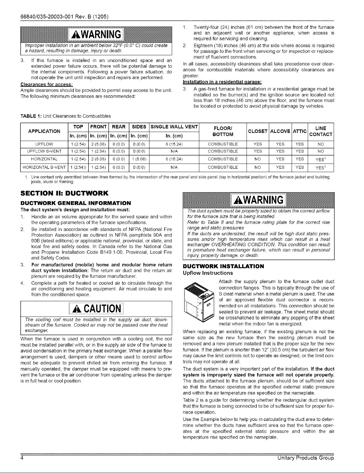
TABLE 1: Unit Clearances to Combustibles
1. Twenty-four (24) inches (61 cm) between the front d the furnace
and an adjacent wall or another appliance, when access is
required for servicing and cleaning.
2. Eighteen (18) inches (46 cm) at the side where access is required
for passage to the front when servicing or for inspection or replace-
ment of flue/vent connections.
In all cases, accessibility clearances shall take precedence over clear-
ances for combustible materials where accessibility clearances are
greater.
Installation in a residential aaraoe:
3. A gas-fired furnace for installation in a residential garage must be
installed so the burner(s) and the ignition source are located not
less than 18 inches (46 cm) above the floor, and the furnace must
be located or protected to avoid physical damage by vehicles.
APPLICATION
TOP FRONT REAR SIDES SINGLE WALL VENT
In. (cm) In, (cm) In. (cm) In. (cm) In. (cm)
UPFLOW 1 (254) 2 (5.08) 0 (0.0) 0 (00) 6 (1524)
UPFLOW B-VENT 1 (254) 1 (2.54) 0 (0.0) 0 (00) N/A
HORIZONTAL 1 (254) 2 (5.08) 0 (0.0) 1 (5.08) 6 (1524)
HORIZONTAL B-VENT 1 (2.54)) 1 (254) 0 (0.0) 0 (00) N/A
1. Line contact only permitted between lines formed by the intersection of the rear paneI and side paneI (top in horizontal position) of the furnace jacket and buitding
joists, studs or framing
FLOOR/ LINE
BOTTOM CONTACT
COMBUSTIBLE YES YES YES NO
COMBUSTIBLE YES YES YES NO
COMBUSTIBLE NO YES YES YES 1
COMBUSTIBLE NO YES YES YES 1
CLOSET ALCOVE ATTIC
SECTION Ih DUCTWORK
DUCTWORK GENERAL INFORMATION
The duct system's design and installation must:
1. Handle an air volume appropriate for the served space and within
the operating parameters of the furnace specifications.
2. Be installed in accordance with standards of NFPA (National Fire
Protection Association) as outlined in NFPA pamphlets 90A and
90B (latest editions) or applicable national, provincial, or state, and
local fire and safety codes. In Canada refer to the National Gas
and Propane Installation Code B149.!-00, Provincial, Local Fire
and Safety Codes.
3. For manufactured (mobile) home and modular home return
duct system installation: The return air duct and the return air
plenum are required by the furnace manufacturer.
4. Complete a path for heated or cooled air to circulate through the
air conditioning and heating equipment. Air must circulate to and
from the conditioned space.
A CAUTION
The cooling coil must be installed in the supply air duct, down-
stream of the furnace. Cooled air may not be passed over the heat
exchanger.
When the furnace is used in conjunction with a cooling coil, the coil
must be installed parallel with, or in the supply air side of the furnace to
avoid condensation in the primary heat exchanger. When a parallel flow
arrangement is used, dampers or other means used to control airflow
must be adequate to prevent chilled air from entering the furnace. If
manually operated, the damper must be equipped with means to pre-
vent the furnace or the air conditioner from operating unless the damper
is in full heat or cool position.
The duct system must be properly sized to obtain the correct airflow
for the furnace size that is being installed.
Refer to Table 8 and the furnace rating plate for the correct rise
range and static pressures
If the ducts are undersized, the result will be high duct static pres-
sures and/or high temperature rises which can result in a heat
exchanger OVERHEATING CONDITION. This condition can result
in premature heat exchanger failure, which can result in personal
injury, property damage, or death.
DUCTWORK INSTALLATION
Upflow Instructions
When replacing an existing furnace, if the existing plenum is not the
same size as the new furnace then the existing plenum must be
removed and a new plenum installed that is the proper size for the new
furnace. If the plenum is shorter than 12" (30.5 cm) the turbulent air flow
may cause the limit controls not to operate as designed, or the limit con-
trois may not operate at all.
The duct system is a very important part of the installation. If the duct
system is improperly sized the furnace will not operate properly.
The ducts attached to the furnace plenum, should be of sufficient size
so that the furnace operates at the specified external static pressure
and within the air temperature rise specified on the nameplate.
Table 2 is a guide for determining whether the rectangular duct system
that the furnace is being connected to be of sufficient size for proper fur-
nace operation.
Use the Example below to help you in calculating the duct area to deter-
mine whether the ducts have sufficient area so that the furnace oper-
ates at the specified external static pressure and within the air
temperature rise specified on the nameplate.
kWARNING
Attach the supply plenum to the furnace outlet duct
S cleat material when a metal plenum is used. The use
of an approved flexible duct connector is recom-
mended on all installations. This connection should be
connection flanges. This is typically through the use of
sealed to prevent air leakage. The sheet metal should
be crosshatched to eliminate any popping of the sheet
metal when the indoor fan is energized.
4 Unitary Products Group
Page 5
66840/035-20003-001 Rev. B (1205)
Example:Thefurnaceinputis80,000BTUH,1,200CFM.Therecom-
mendedductareais280sq.in,therearetwo8x14rectangularducts
attachedtotheplenumandtherearetwo7inchroundductsattachedto
thefurnace.
1. Take8x14,whichequals112sq.in.X2,whichequals224square
inchthengotoroundductsizelocatedinTable2.
2. Thesquareinchareafor7inchroundpipeis38.4,multiplyby2for
tworoundductswhichequals76.8squareinch.
3. Thentakethe224squareinchfromtherectangularductandaddit
tothe76.8sq.in,ofroundduct.Thetotalsquareinchofduct
attachedtothefurnaceplenumis300.8squareinch.Thisexceeds
therecommended280squareinchofduct.
Inthisexample,theductsystemattachedtotheplenumhasasufficient
areasothatthefurnaceoperatesatthespecifiedexternalstaticpres-
sureandwithintheairtemperaturerisespecifiedonthenameplate.
Considerationshouldbegiventotheheatingcapacityrequiredandalso
totheairquantity(CFM)required.Thesefactorscanbedeterminedby
calculatingtheheatlossandheatgainofthehomeorstructure.Ifthese
calculationsarenotperformedandthefurnaceisover-sized,thefollow-
ingmayresult:
1. Shortcyclingofthefurnace.
2. Widetemperaturefluctuationsfromthethermostatsetting.
3. Reducedoveralloperatingefficiencyofthefurnace.
Thesupplyandreturnductsystemmustbeofadequatesizeand
designedsuchthatthefurnacewilloperatewithinthedesignedairtem-
peratureriserangeandnotexceedthemaximumdesignedstaticpres-
sure.Thesevaluesarelistedinthetablebelow.
TABLE2:MinimumDuctSizingForProperAirflow
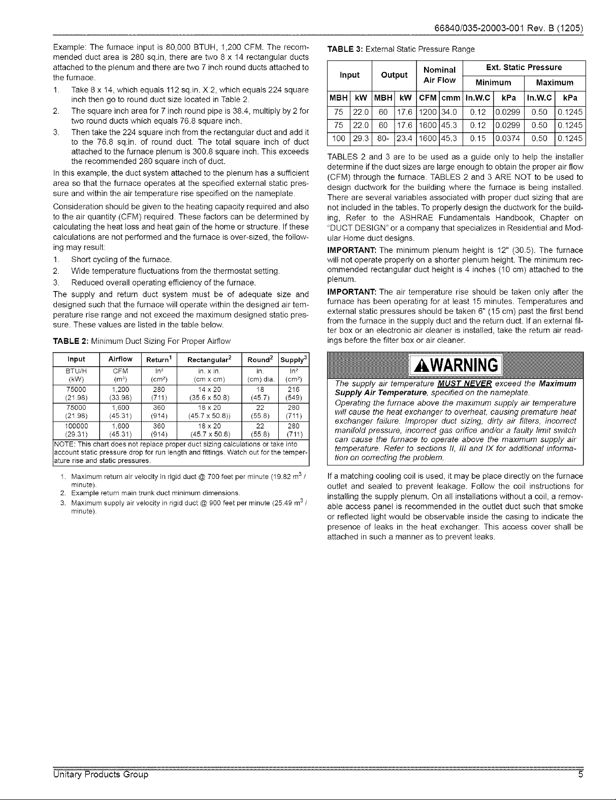
TABLE 3: External Static Pressure Range
Input Output
MBH kW MBH kW
75 22.0 60 17.6
75 22.0 60 17.6
100 29.3 80- 23.4
TABLES 2 and 3 are to be used as a guide only to help the installer
determine if the duct sizes are large enough to obtain the proper air flow
(CFM) through the furnace. TABLES 2 and 3 ARE NOT to be used to
design ductwork for the building where the furnace is being installed.
There are several variables associated with proper duct sizing that are
not included in the tables. To properly design the ductwork for the build-
ing, Refer to the ASHRAE Fundamentals Handbook, Chapter on
"DUCT DESIGN" or a company that specializes in Residential and Mod-
ular Home duct designs.
IMPORTANT: The minimum plenum height is 12" (30.5). The furnace
will not operate properly on a shorter plenum height. The minimum rec-
ommended rectangular duct height is 4 inches (10 cm) attached to the
plenum.
IMPORTANT: The air temperature rise should be taken only after the
furnace has been operating for at least 15 minutes. Temperatures and
external static pressures should be taken 6" (15 cm) past the first bend
from the furnace in the supply duct and the return duct. If an external fil-
ter box or an electronic air cleaner is installed, take the return air read-
ings before the filter box or air cleaner.
Nominal
Air Flow
CFM cmm
1200 34.0
1600 45.3
1600 45.3
Ext. Static Pressure
Minimum Maximum
In.W.C kPa In.W.C kPa
0.12 0.0299 0.50 0.!245
0.12 0.0299 0.50 0.1245
0.15 0.0374 0.50 0.!245
Input
BTU/H
(kW)
75000
(2198)
75000
(2198)
100000
(2931)
NOTE: This chart does not replace proper duct sizing calculations or take into
account static pressure drop for run length and fittings. Watch out for the temper-
ature rise and static pressures.
1 Maximum return air velocity in rigid duct @ 700 feet per minute (19.82 m3/
minute)
2 Example return main trunk duct minimum dimensions
3 Maximum supply air velocity in rigid duct @ 900 feet per minute (25.49 m3 /
minute)
Airflow Return I Rectangular 2 Round 2 Supply 3
CFM Ins in. x in in Ins
(m 3) (cm _) (cm x cm) (cm) dia. (cm _)
1,200 280 14 x 20 18 216
(3398) (711) (356 x 508) (457) (549)
1,600 360 18 x 20 22 280
(4531) (914) (457 x 508)) (558) (711)
1,600 360 18 x 20 22 280
(4531) (914) (45.7 x 50.8) (558) (711)
The supply air temperature MUST NEVER exceed the Maximum
Supply Air Temperature, specified on the nameplate.
Operating the furnace above the maximum supply air temperature
will cause the heat exchanger to overheat, causing premature heat
exchanger failure. Improper duct sizing, dirty air filters, incorrect
manifold pressure, incorrect gas orifice and/or a faulty limit switch
can cause the furnace to operate above the maximum supply air
temperature. Refer to sections II, III and IX for additional informa-
tion on correcting the problem.
If a matching cooling coil is used, it may be place directly on the furnace
outlet and sealed to prevent leakage. Follow the coil instructions for
installing the supply plenum. On all installations without a coil, a remov-
able access panel is recommended in the outlet duct such that smoke
or reflected light would be observable inside the casing to indicate the
presence of leaks in the heat exchanger. This access cover shall be
attached in such a manner as to prevent leaks.
Unitary Products Group 5
Page 6
66840/035-20003-001Rev.B(1205)
29-3/4
,7 cm) (75,6 cm_.
31-1/2
(80.0 cm)
13-15/16
(85A cm)
(58A cm)
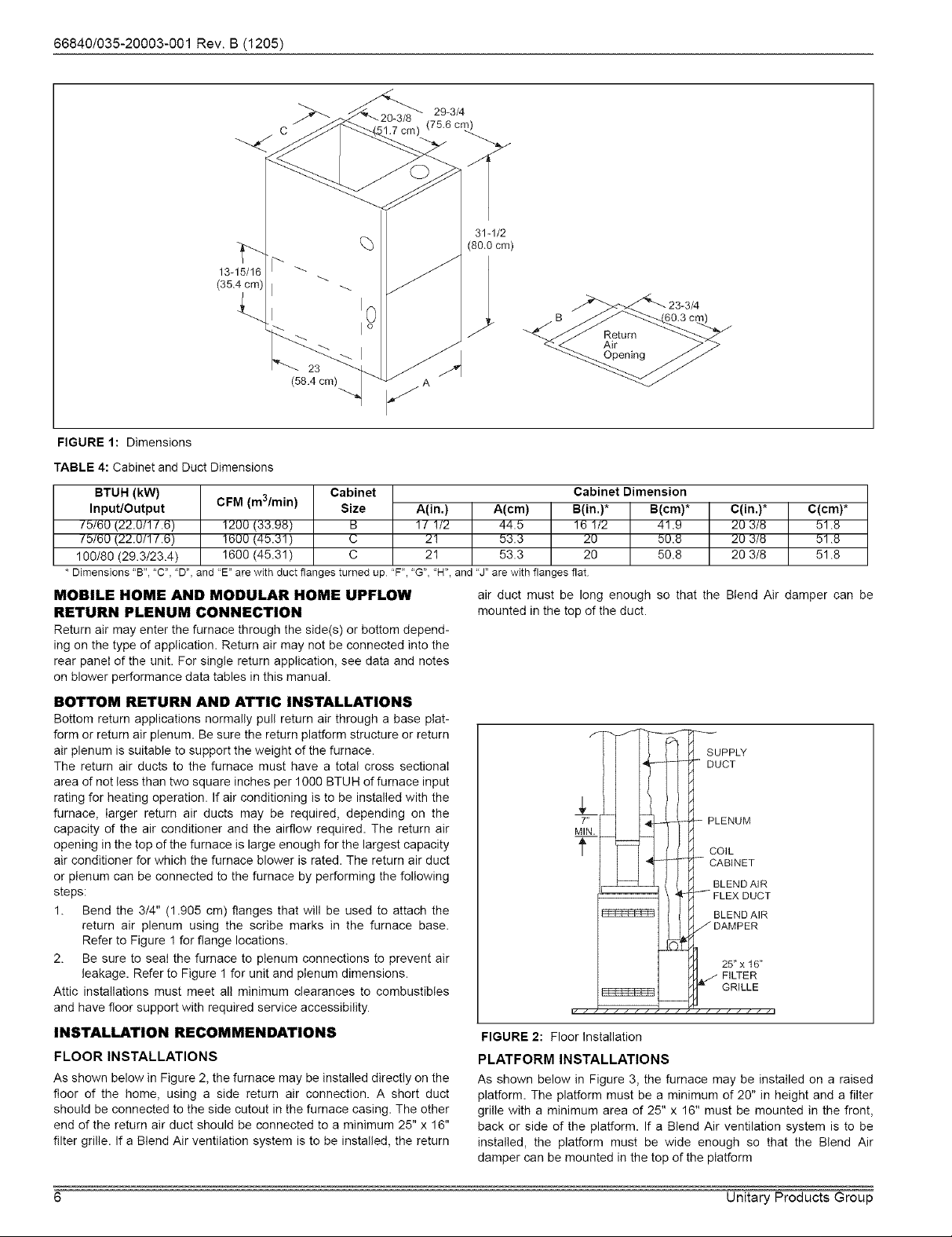
FIGURE 1: Dimensions
TABLE 4: Cabinet and Duct Dimensions
BTUH (kW) Cabinet Cabinet Dimension
Input/Output CFM (m3/min) Size A(in.) A(cm) B(in.)* B(cm)*
/b/6U (22.0/1/.6) 1200 (33.98) B 1 / 1/2 44.b 16 1/2 41.9
/bt6U (22.0/1/.6) !600 (46.31) C 21 53.3 20 50.8
100/80 (29.3/23A) 1600 (45.31) C 21 53.3 20 50.8
* Dimensions "B", "C', "D', and "E" arewith duct flangesturned up "F', "G","H", and "J" are with flanges flat
MOBILE HOME AND MODULAR HOME UPFLOW
RETURN PLENUM CONNECTION
Return air may enter the furnace through the side(s) or bottom depend-
ing on the type of application. Return air may not be connected into the
rear panel of the unit. For single return application, see data and notes
on blower performance data tables in this manual.
BOTTOM RETURN AND ATTIC INSTALLATIONS
Bottom return applications normally pull return air through a base plat-
form or return air plenum. Be sure the return platform structure or return
air plenum is suitable to support the weight of the furnace.
The return air ducts to the furnace must have a total cross sectional
area of not less than two square inches per 1000 BTU H of furnace input
rating for heating operation. If air conditioning is to be installed with the
furnace, larger return air ducts may be required, depending on the
capacity of the air conditioner and the airflow required. The return air
opening in the top of the furnace is large enough for the largest capacity
air conditioner for which the furnace blower is rated. The return air duct
or plenum can be connected to the furnace by performing the following
steps:
1. Bend the 3/4" (1.905 cm) flanges that will be used to attach the
return air plenum using the scribe marks in the furnace base.
Refer to Figure 1 for flange locations.
2. Be sure to seal the furnace to plenum connections to prevent air
leakage. Refer to Figure 1 for unit and plenum dimensions.
Attic installations must meet all minimum clearances to combustibles
and have floor support with required service accessibility.
INSTALLATION RECOMMENDATIONS
FLOOR INSTALLATIONS
As shown below in Figure 2, the furnace may be installed directly on the
floor of the home, using a side return air connection. A short duct
should be connected to the side cutout in the furnace casing. The other
end of the return air duct should be connected to a minimum 25" x 16"
filter grille. If a Blend Air ventilation system is to be installed, the return
air duct must be long enough so that the Blend Air damper can be
mounted in the top of the duct.
1 I I J ( fZZCOIL
[ [l rd CAO'NET
F--_ ( /. H_ BLENDAIR
_I_ FLEX DUCT
_I I # [_ BLEND AIR
_-GRILLrT=._ E
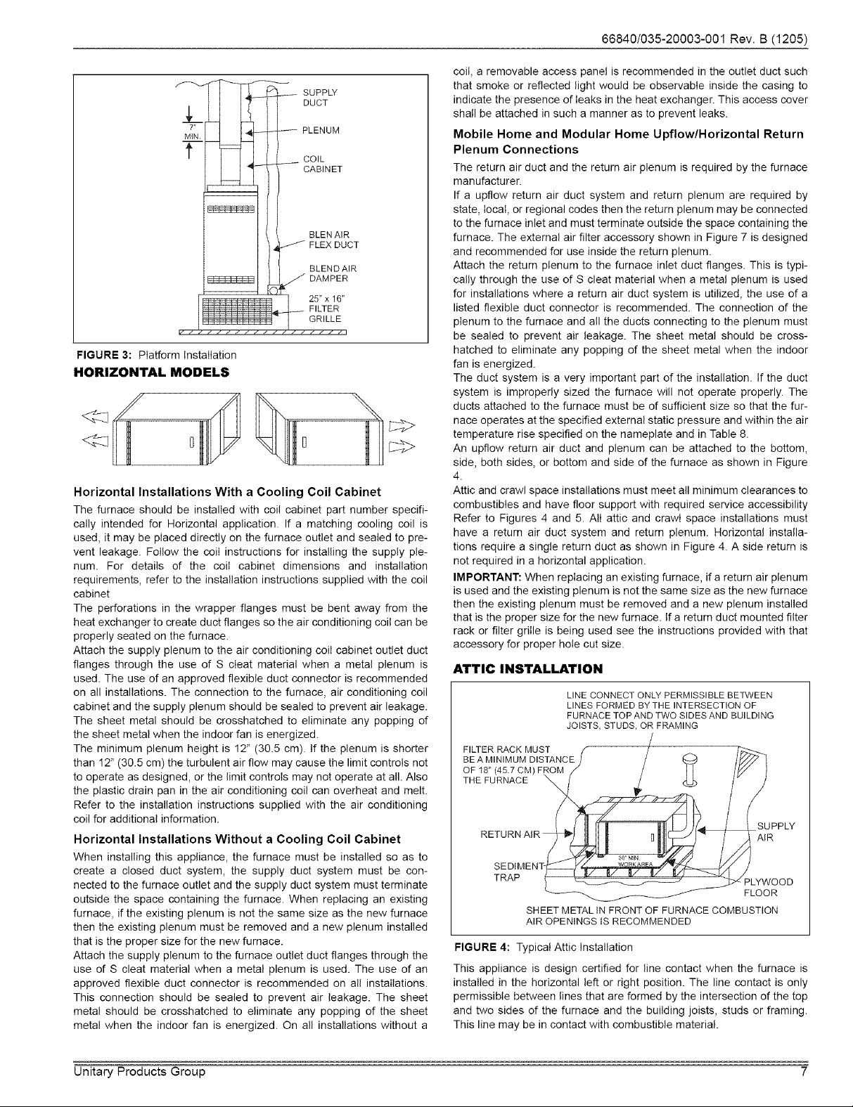
FIGURE 2: Floor Installation
PLATFORM INSTALLATIONS
As shown below in Figure 3, the furnace may be installed on a raised
platform. The platform must be a minimum of 20" in height and a filter
grille with a minimum area of 25" x 16" must be mounted in the front,
back or side of the platform. If a Blend Air ventilation system is to be
installed, the platform must be wide enough so that the Blend Air
damper can be mounted in the top of the platform
C(in.)* C(cm)*
20 3/8 t1.8
20 3/8 51 .U
20 3/8 51.8
PLENOM
/DAMPER
I _[ 25"x 18"
I H _ FILTER
6 Unitary Products Group
Page 7
25" x 16"
FILTER
GRILLE
FIGURE 3: Platform Installation
HORIZONTAL MODELS
Horizontal Installations With a Cooling Coil Cabinet
The furnace should be installed with coil cabinet part number specifi-
cally intended for Horizontal application. If a matching cooling coil is
used, it may be placed directly on the furnace outlet and sealed to pre-
vent leakage. Fellow the ceiI instructions for installing the supply ple-
num. For details of the coiI cabinet dimensions and installation
requirements, refer to the installation instructions supplied with the coil
cabinet
The perforations in the wrapper flanges must be bent away from the
heat exchanger to create duct flanges so the air conditioning ceil can be
properly seated on the furnace.
Attach the supply plenum to the air conditioning coiI cabinet outlet duct
flanges through the use of S cleat material when a metal plenum is
used. The use of an approved flexible duct connector is recommended
on all installations. The connection to the furnace, air conditioning coil
cabinet and the supply plenum should be sealed to prevent air leakage.
The sheet metal should be crosshatched to eliminate any popping of
the sheet metal when the indoor fan is energized.
The minimum plenum height is 12" (30.5 cm). If the plenum is shorter
than 12" (30.5 cm) the turbulent air flow may cause the limit controls not
to operate as designed, or the limit controls may not operate at all. Also
the plastic drain pan in the air conditioning coil can overheat and melt.
Refer to the installation instructions supplied with the air conditioning
coil for additional information.
Horizontal Installations Without a Cooling Coil Cabinet
When installing this appliance, the furnace must be installed so as to
create a closed duct system, the supply duct system must be con-
nected to the furnace outlet and the supply duct system must terminate
outside the space containing the furnace. When replacing an existing
furnace, if the existing plenum is not the same size as the new furnace
then the existing plenum must be removed and a new plenum installed
that is the proper size for the new furnace.
Attach the supply plenum to the furnace outlet duct flanges through the
use of S cleat material when a metal plenum is used. The use of an
approved flexible duct connector is recommended on all installations.
This connection should be sealed to prevent air leakage. The sheet
metal should be crosshatched to eliminate any popping of the sheet
metal when the indoor fan is energized. On all installations without a
66840/035-20003-001 Rev. B (1205)
coil, a removable access panel is recommended in the outlet duct such
that smoke or reflected light would be observable inside the casing to
indicate the presence of leaks in the heat exchanger. This access cover
shall be attached in such a manner as to prevent leaks.
Mobile Home and Modular Home Upflow/Horizontal Return
Plenum Connections
The return air duct and the return air plenum is required by the furnace
manufacturer.
If a upflow return air duct system and return plenum are required by
state, local, or regional codes then the return plenum may be connected
to the furnace inlet and must terminate outside the space containing the
furnace. The external air filter accessory shown in Figure 7 is designed
and recommended for use inside the return plenum.
Attach the return plenum to the furnace inlet duct flanges. This is typi-
cally through the use of S cleat material when a metal plenum is used
for installations where a return air duct system is utilized, the use of a
listed flexible duct connector is recommended. The connection of the
plenum to the furnace and all the ducts connecting to the plenum must
be sealed to prevent air leakage. The sheet metal should be cross-
hatched to eliminate any popping of the sheet metal when the indoor
fan is energized.
The duct system is a very important part of the installation. If the duct
system is improperly sized the furnace will not operate properly. The
ducts attached to the furnace must be of sufficient size so that the fur-
nace operates at the specified external static pressure and within the air
temperature rise specified on the nameplate and in Table 8.
An upflow return air duct and plenum can be attached to the bottom,
side, both sides, or bottom and side of the furnace as shown in Figure
4.
Attic and crawl space installations must meet all minimum clearances to
combustibles and have floor support with required service accessibility
Refer to Figures 4 and 5. All attic and crawl space installations must
have a return air duct system and return plenum. Horizontal installa-
tions require a single return duct as shown in Figure 4. A side return is
not required in a horizontal application.
IMPORTANT: When replacing an existing furnace, if a return air plenum
is used and the existing plenum is not the same size as the new furnace
then the existing plenum must be removed and a new plenum installed
that is the proper size for the new furnace. If a return duct mounted filter
rack or filter grille is being used see the instructions provided with that
accessory for proper hole cut size.
ATTIC INSTALLATION
LINE CONNECT ONLY PERMISSIBLE BETWEEN
LINES FORMED BY THE INTERSECTION OF
FURNACE TOP AND TWO SIDES AND BUILDING
JOISTS, STUDS, OR FRAMING
FILTER RACK MUST
BE A MI NIMUM DISTANCE
OF 18" (45.7 CM) F!
THE FURNACE
SUPPLY
AIR
TRAP
SHEET METAL IN FRONT OF FURNACE COMBUSTION
AIR OPENINGS IS RECOMMENDED
FIGURE 4: Typical Attic Installation
This appliance is design certified for line contact when the furnace is
installed in the horizontal left or right position. The line contact is only
permissible between lines that are formed by the intersection of the top
and two sides of the furnace and the building joists, studs or framing.
This line may be in contact with combustible material.
PLYWOOD
FLOOR
Unitary Products Group 7
Page 8
66840/035-20003-001Rev.B(1205)
When a furnace is installed in an attic or other insulated space,
keep all insulating materials at least 12 inches (30.5 Cm) away from
furnace and burner combustion air openings.
SUSPENDED FURNACE / CRAWL SPACE
INSTALLATION
The furnace can be hung from floor joists or installed on suitable blocks
or pad. Blocks or pad installations shall provide adequate height to
ensure the unit will not be subject to water damage. Units may also be
suspended from rafters or floor joists using rods, pipe angle supports or
straps. Angle supports should be placed at the supply air end and near
the blower deck. Do not support at return air end of unit. All four sus-
pension points must be level to ensure quiet furnace operation. When
suspending the furnace, use a secure platform constructed of plywood
or other building material secured to the floor joists. Refer to Figure 5
for typical crawl space installation.
ANGLE IRON
BRACKET
SUPPORT
ROD
1"MAX, BETWEEN 6"MtN BETWEEN
ROD & FURNACE ROD & FURNACE
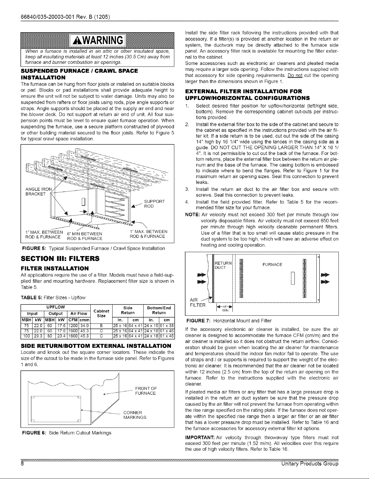
FIGURE 5: Typical Suspended Furnace / Crawl Space Installation
SECTION IIh FILTERS
FILTER INSTALLATION
All applications require the use of a filter. Models must have a field-sup-
plied filter and mounting hardware. Replacement filter size is shown in
Table 5.
TABLE 5: Filter Sizes - Upflow
UPFLOW Side
Input Output Air Flow Size
MBH kW MBH kW CFM cmrn in. crn
75 220 60 17.6 1200 34.0 B 25x16 64x41
75 220 60 17.6 1600 45.3 C 25x16 64x41
100 293 80 23.4 1600 45.3 C 25x16 64x41
SIDE RETURN/BOTTOM EXTERNAL INSTALLATION
Locate and knock out the square corner Iocators. These indicate the
size of the cutout to be made in the furnace side panel. Refer to Figures
1 and 6.
r
I I _ CORNER
Iq FJ J_ MARKINGS
FIGURE 6: Side Return Cutout Markings
Cabinet Return
1"MAX, BETWEEN
ROD & FURNACE
Bottom/End
in. cm
24x 15 61 x38
24x 18 61 x46
24x 18 61 x46
_ FRONT OF
Return
Install the side filter rack following the instructions provided with that
accessory. If a filter(s) is provided at another location in the return air
system, the ductwork may be directly attached to the furnace side
panel. An accessory filter rack is available for mounting the filter exter-
nal to the cabinet.
Some accessories such as electronic air cleaners and pleated media
may require a larger side opening. Follow the instructions supplied with
that accessory for side opening requirements. Do not cut the opening
larger than the dimensions shown in Figure 1.
EXTERNAL FILTER INSTALLATION FOR
UPFLOW/HORIZONTAL CONFIGURATIONS
1. Select desired filter position for upfiow/horizontal (left/right side,
bottom). Remove the corresponding cabinet cut-outs per instruc-
tions provided.
2. Install the external filter box to the side of the cabinet and secure to
the cabinet as specified in the instructions provided with the air fil-
ter kit. If a side return is to be used, cut out the side of the casing
14" high by 16 1/4" wide using the lances in the casing side as a
guide. DO NOT CUT THE OPENING LARGER THAN 14" X 16 1/
4". It is not permissible to cut out the back of the furnace. For bot-
tom returns, place the external filter box between the return air ple-
num and the base of the furnace. The casing bottom is embossed
to indicate where to bend the flanges. Refer to Figure ! for the
maximum return air opening sizes. Seal this connection to prevent
leaks.
3. Install the return air duct to the air filter box and secure with
screws. Seal this connection to prevent leaks.
4. Install the field provided filter. Refer to Table 5 for the recom-
mended filter size for your furnace.
NOTE: Air velocity must not exceed 300 feet per minute through low
velocity disposable filters. Air velocity must not exceed 650 feet
per minute through high velocity cIeanable permanent filters.
Use d a filter that is too small will cause static pressure in the
duct system to be too high, which will have an adverse effect on
heating and cooling operation.
RETURN
DUCT
AIR__ _F
FILTER
FIGURE 7: Horizontal Mount and Filter
If the accessory electronic air cleaner is installed, be sure the air
cleaner is designed to accommodate the furnace CFM (cm/m) and the
air cleaner is installed so it does not obstruct the return airfow. Consid-
eration should be given when locating the air cleaner for maintenance
and temperatures should the indoor fan motor fail to operate. The use
of straps and / or supports is required to support the weight of the elec-
tronic air cleaner. It is recommended that the air cleaner not be located
within 12 inches (2.5 cm) from the top of the return air opening on the
furnace. Refer to the instructions supplied with the electronic air
cleaner.
If pleated media air filters or any filter that has a large pressure drop is
installed in the return air duct system be sure that the pressure drop
caused by the air filter will not prevent the furnace from operating within
the rise range specified on the rating plate. If the furnace does not oper-
ate within the specified rise range then a larger air filter or an air filter
that has a lower pressure drop must be installed. Refer to Table 16 and
the furnace accessories for accessory external filter kit options.
IMPORTANT: Air velocity through throwaway type filters must not
exceed 300 feet per minute (1.52 m/m). All velocities over this require
the use of high velocity filters. Refer to Table 16.
[] []
[] FURNACE []
[]
[]
[] D
[]
[]
[]
MN I
[]
[]
8 Unitary Products Group
Page 9
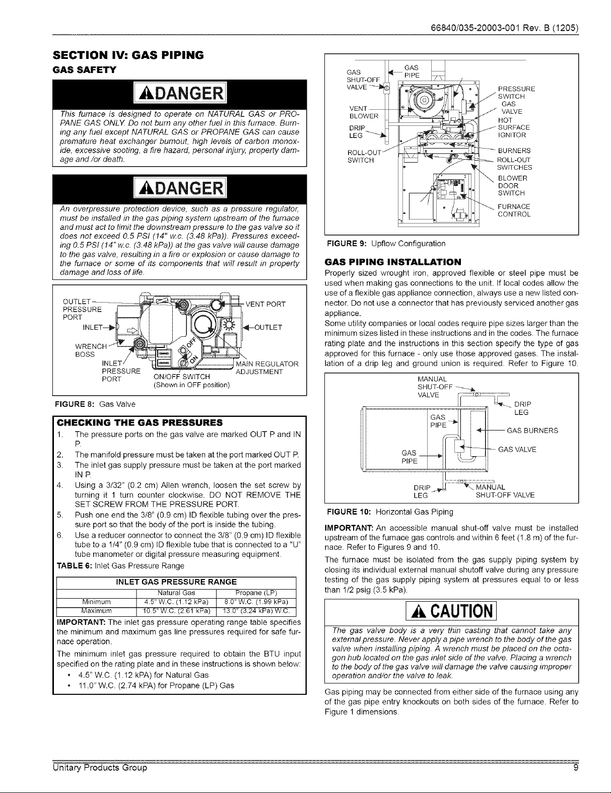
SECTION IV: GAS PIPING
GAS SAFETY
kDANGER
This furnace is designed to operate on NATURAL GAS or PRO-
PANE GAS ONLX Do not burn any other fuel in this furnace. Bum-
ing any fuel except NATURAL GAS or PROPANE GAS can cause
premature heat exchanger burnout, high levels of carbon monox-
ide, excessive sooting, a fire hazard, personal injury, property dam-
age and/or death.
An overpressure protection device, such as a pressure regulator,
must be installed in the gas piping system upstream of the furnace
and must act to limit the downstream pressure to the gas valve so it
does not exceed 0.5 PSI (14" w.c. (3.48 kPa)). Pressures exceed-
ing 0.5 PSI (14" w.c. (3.48 kPa)) at the gas valve will cause damage
to the gas valve, resulting in a fire or explosion or cause damage to
the furnace or some of its components that wil! result in property
damage and loss of life.
OUTLET
PRESSURE r! I_] I'_
PORT L_ I I
WRENCH _ _
BOSS __
INLET/
PRESSURE
PORT
ON/OFF SWITCH
(Shown in OFF position)
FIGURE 8: Gas Valve
VENT PORT
OUTLET
N REGULATOR
ADJUSTMENT
66840/035-20003-001Rev.B(1205)
GAS _ PIPE
SHUT-OFF
VALVE
VENT --
BLOWER
DRIP
LEG --_
ROLL-OUT _
SWITCH
FIGURE 9: Upflow Configuration
GAS PIPING INSTALLATION
Properly sized wrought iron, approved flexible or steel pipe must be
used when making gas connections to the unit. If local codes allow the
use of a flexible gas appliance connection, always use a new listed con-
nector. Do not use a connector that has previously serviced another gas
appliance.
Some utility companies or local codes require pipe sizes larger than the
minimum sizes listed in these instructions and in the codes. The furnace
rating plate and the instructions in this section specify the type of gas
approved for this furnace - only use those approved gases. The instal-
lation of a drip leg and ground union is required. Refer to Figure 10.
GAS
MAN UAL
SHUT-OFF
VALVE
PRESSURE
GAS
VALVE
HOT
IGNITOR
ROLL-OUT
SWITCHES
BLOWER
DOOR
SWITCH
FURNACE
CONTROL
CHECKING THE GAS PRESSURES
1. The pressure ports on the gas valve are marked OUT P and IN
R
2. The manifold pressure must be taken at the port marked OUT R
3. The inlet gas supply pressure must be taken at the port marked
INP.
4. Using a 3/32" (0.2 cm) Allen wrench, loosen the set screw by
turning it 1 turn counter clockwise. DO NOT REMOVE THE
SET SCREW FROM THE PRESSURE PORT.
5. Push one end the 3/8" (0.9 cm) ID flexible tubing over the pres-
sure port so that the body of the port is inside the tubing.
6. Use a reducer connector to connect the 3/8" (0.9 cm) ID flexible
tube to a 1/4" (0.9 cm) ID flexible tube that is connected to a "U"
tube manometer or digital pressure measuring equipment.
TABLE 6: Inlet Gas Pressure Range
INLET GAS PRESSURE RANGE
Natural Gas Propane (LP)
Minimum 45" W.C (1 12 kPa) 80" W.C (1 99 kPa)
Maximum 105" W.C. (261 kPa) 130" (3.24 kPa) WC.
IMPORTANT: The inlet gas pressure operating range table specifies
the minimum and maximum gas line pressures required for safe fur-
nace operation.
The minimum inlet gas pressure required to obtain the BTU input
specified on the rating plate and in these instructions is shown below:
• 4.5" W.C. (1.12 kPA) for Natural Gas
• 11.0" W.C. (2.74 kPA) for Propane (LP) Gas
--GAS BURNERS
-- GAS VALVE
HI....................................................................3
DRIP MANLJAL
LEG SHUT-OFF VALVE
FIGURE 10: Horizontal Gas Piping
IMPORTANT: An accessible manual shut-off valve must be installed
upstream of the furnace gas controls and within 6 feet (! .8 m) of the fur-
nace. Refer to Figures 9 and 10.
The furnace must be isolated from the gas supply piping system by
closing its individual external manual shutoff valve during any pressure
testing of the gas supply piping system at pressures equal to or less
than 1/2 psig (3.5 kPa).
CAUTION]
The gas valve body is a very thin casting that cannot take any
external pressure. Never apply a pipe wrench to the body of the gas
valve when installing piping. A wrench must be placed on the octa-
gon hub located on the gas inlet side of the valve. Placing a wrench
to the body of the gas valve wil! damage the valve causing improper
operation and/or the valve to leak.
Gas piping may be connected from either side of the furnace using any
of the gas pipe entry knockouts on both sides of the furnace. Refer to
Figure ! dimensions.
Unitary Products Group 9
Page 10

66840/035-20003-001Rev.B(1205)
GAS ORIFICE CONVERSION FOR PROPANE (LP)
Refer to Table 7 for the proper gas orifice size.
The conversion shall be installed by a qualified service agency in
accordance with the manufacturer's instructions and all applicable
codes and requirements of the authority having jurisdiction. If the
information in these instructions is not followed exactly, a fire, an
explosion or production of carbon monoxide may result causing
property damage, personal injury or loss of life. The qualified ser-
vice agency is responsible for the proper installation. The installa-
tion is not proper and complete until the operation of the converted
appliance is checked as specified in the manufacturer's instruc-
tions.
Improper installation may damage equipment, can create a shock
hazard, and will void the warranty,
IMPORTANT: These instructions are for the use of qualified individuals
specially trained, experienced and certified in the installation d this type
of equipment and related system components. Installation and service
personnel are required by some states to be licensed. Persons not
qualified shall not install this equipment nor interpret these instructions.
NOTE: The words "Shall" or "Must" indicate a requirement, which is
essential to satisfactory and safe product performance.
NOTE: The words "Should" or "May" indicate a recommendation or
advice which is not essential and not required but which may be
useful or helpful.
CONTENTS
1. Burner orifices for LP (propane) gas are located in bag attached to
the gas valve.
2. Conversion plate.
BURNER GAS VALVE
GAS
ORIFICE GAS
FIGURE 11: Burner Assembly
CONVERSION PROCEDURE
MANIFOLD
1. Shut off gas supply at valve upstream from furnace or at meter as
required. Refer to Figures 9 and 10.
2. Disconnect as supply piping from gas valve on furnace.
3. Disconnect electrical wires from gas valve, nothing which wires
are connected to which terminals.
4. Remove the four screws that attach the gas manifold to the burner
support box. See Figure 11.
5. Remove and discard natural gas orifices.
6. Remove LP (Propane) orifices from the bag attached to the gas
valve.
7. Install the LP (Propane) gas orifices supplied with the furnace.
Tighten to 15 - 25 inch - pounds of torque.
8. Reinstall the manifold in the assembly by reversing the removal
process.
9. Reconnect the wires to the proper terminals on the gas valve.
10. Remove the regulator with the blue cap and turn it upside down so
the letters "LP" are upright. Place the blue cap on the opposite end
of the regulator.
11. Convert the gas valve for LP (propane) gas operation by following
the instructions. Remove the natural tag and replace with the pro-
pane tag supplied in the orifice bag to the gas burner mounting
plate to show that is has been converted.
12. Remove the blue conversion label on the furnace door after the
furnace has been converted.
13. Reconnect the gas supply piping to the gas valve and insure that
all gas connections are tight.
14. Remove pressure tap plugs from gas valve and connect water
gauge to the pressure tap ports. See Figure 8 for location of the
gas valve pressure taps and pressure regulator adjustment.
15. Turn on gas supply to furnace and check all gas connections with
suitable leak detector.
Never use an open flame to check for leaks. Fire or explosion could
occur. Since some leak solutions including soap and water may
cause corrosion or stress cracking, the piping must be rinsed with
water after testing unless it has been determined that the leak test
solution is non-corrosive.
HIGH ALTITUDE GAS ORIFICE CONVERSION
This furnace is constructed at the factory for natural gas-fired operation
at 0 - 2,000 ft. (0 m - 610 m) above sea level.
The gas orifices on this furnace must be changed in order to maintain
proper and safe operation, when the furnace is installed in a location
where the altitude is greater than 2,000 ft. (610 m) above sea level on
natural gas or the altitude is greater than 4,000 ft. (1219 m) above sea
level on propane (LP) gas. Refer to Table 7 or the instructions in the
high altitude conversion kit for the proper gas orifice size.
The unit may also be converted for altitudes up to !0,000 ft. (3048 m)
on natural and propane (LP) gas with additional derate as shown in
Table 7 or refer to ANSI Z223.1 NFPA 54 National Fuel Gas Code or in
Canada CAN/CGA-B149.1-00 Natural Gas and Propane Installation
Code.
CAUTION]
The gas supply must be shut off prior to disconnecting the electrical
power, before proceeding with the conversion.
AWARNING
SHOCK HAZARD - Turn off electrical supply to furnace
10 Unitary Products Group
Page 11

66840/035-20003-001Rev.B(1205)
AkDANGER
PROPANE AND HIGH ALTITUDE CONVERSION KITS
It is very important to choose the correct kit and/or gas orifices for
the altitude and the type of gas for which the furnace is being
installed.
Only use natural gas in furnaces designed for natural gas. Only use
propane (LP) gas for furnaces that have been properly converted to
use propane (LP) gas. Do not use this furnace with butane gas.
Incorrect gas orifices or a furnace that has been improperly con-
verted will create an extremely dangerous condition resulting in pre-
mature heat exchanger failure, excessive sooting, high levels of
carbon monoxide, personal injury, property damage, a fire hazard
and/or death.
High altitude and propane (LP) conversions are required in order
for the appliance to satisfactory meet the application.
An authorized distributor or dealer must make all gas conversions.
In Canada, a certified conversion station or other qualified agency,
using factory specified and/or approved parts, must perform the
conversion.
The installer must take every precaution to insure that the furnace
has been converted to the proper gas orifice size when the furnace
is installed. Do not attempt to drill out any orifices to obtain the
proper orifice size. Drilling out a gas orifice will cause misallgnment
of the burner flames, causing premature heat exchanger burnout,
high levels of carbon monoxide, excessive sooting, a fire hazard,
personal injury, property damage and/or death.
TABLE 8: Ratings & Physical / Electrical Data - Upflow Models
Input
MBH kW
75 22.0
75 22.0
100 29.3
Input
MBH kW
75 22.0
75 22.0
100 29.3
Wire size and over current protection must comply with the National Electrical Code (NFPA-70-1atest edition) and all locaI codes.
AFUE 80%.
SUPPLY VOLTAGE CONNECTIONS
1. Provide a power supply separate from all other circuits. Install
overcurrent protection and disconnect switch per local/national
electrical codes. The switch should be close to the unit for conve-
nience in servicing. With the disconnect or fused switch in the OFF
position, check all wiring against the unit wiring label. Refer to the
wiring diagram in this instruction.
2. Remove the screws retaining the wiring box cover. Route the
power wiring through the opening in the unit into the junction box
with a conduit connector or other proper connection. In the junc-
tion box there will be three wires (a Black Wire, a White Wire and a
Green Wire). Connect the power supply as shown on the unit-wir-
ing label on the inside of the blower compartment door or the wir-
ing schematic in this section. The black furnace lead must be
connected to the L1 (hot) wire from the power supply. The white
furnace lead must be connected to neutral. Connect the green fur-
nace lead (equipment ground) to the power supply ground. An
alternate wiring method is to use a field provided 2" (5.1 cm) x 4"
(10.2 cm) box and cover on the outside of the furnace. Route the
furnace leads into the box using a protective bushing where the
wires pass through the furnace panel. After making the wiring con-
nections replace the wiring box cover and screws. Refer to Figure
12.
3. The furnace's control system requires correct polarity of the power
supply and a proper ground connection. Refer to Figure 12.
Output
MBH kW
60 17.6
60 17.6
80 23.4
Max. Outlet
Air Temp
°F °C
!65 73.9
160 7! .1
!70 76.7
Nominal
CFM cmm
1200 34.0
1600 45.3
1600 45.3
Blower
Hp Amps
!/3 6.2
1/2 6.2
!/2 7.0
Cabinet Width Air Temp. Rise
In. cm AFUE °F °C
16 7/8 44.45 80.0 35-65 19.4-36.1
20 53.34 80.0 30-60 16.7-33.3
20 53.34 80.0 40-70 22.2-38.9
Blower Total Max Over-current Min.
Size Unit Size (awg) @ 76 ft. Wire
In. cm amps protect one way
10x8 25.4 x 20.3 6.7 15 14
10x!0 25.4 x 25.4 8.5 15 14
10x!0 25.4 x 25.4 8.5 15 14
TABLE 7: High Altitude Conversion
Type Orifice at 2,000 ft. 3,000 ft. 4,000 ft. 5,000 ft.
Of Gas Sea Level (610 m) (914m) (1219 m) (1624 m)
Natural #42 #42 #43 #43 #43
Propane #54 #54 #55 #55 #55
Type 6,000 ft. 7,000 ft. 8,000 ft. 9,000 ft. 10,000 ft.
Of Gas (1829 m) (2134 m) (2438 m) (2743 m) (3048 m)
Natural #44 #44 #45 #46 #47
Propane #55 #55 #56 #56 #56
SECTION V: ELECTRICAL POWER
Electrical Power Connections
Field wiring to the unit must be grounded. Electric wires that are field
installed shall conform to the temperature limitation for 63°F (35°C) rise
wire when installed in accordance with instructions. Refer to Table 8 in
these instructions for specific furnace electrical data.
A. CAUTIONI
Use copper conductors only.
B ._ BL_O_]
_WHT (NEUTRAL) j, NOMINAL120VOLT
GRN _..GRN
FIGURE 12: Line Wiring Connections
IMPORTANT: The power connection leads and wiring box may be relo-
cated to the left side of the furnace. Remove the screws and cut wire tie
holding excess wiring. Reposition on the left side of the furnace and fas-
ten using holes provided.
LOW VOLTAGE CONTROL WIRING CONNECTIONS
Install the field-supplied thermostat by following the instructions that
come with the thermostat. With the thermostat set in the OFF position
and the main electrical source disconnected, connect the thermostat
wiring from the wiring connections on the thermostat to the terminal
board on the ignition module, as shown in Figure 13. Electronic thermo-
stats may require the common wire to be connected as shown with the
dashed line in Figure 13. Apply strain relief to thermostat wires passing
through cabinet. If air conditioning equipment is installed, use thermo-
stat wiring to connect the Y and C terminals on the furnace control
board to the yellow and brown wires on the condensing unit (unit out-
side). Refer to Figure 13.
Operation Operation
WGT. WGT.
LBS Kg
1!6 53.5
129 58.5
135 61.2
Unitary Products Group 11
Page 12

66840/035-20003-001Rev.B(1205)
Room Furnace Condensing
Thermostat Control Unit
Controls
_, ......................
ToAir Conditioner
Common Trstat Connection
FIGURE 13: Heating and Cooling Thermostat Connections
Room Furnace Condensing
Thermostat Control Unit
....... !!!!!!!!!!!!!!!!!!!
FIGURE 14: Two-Stage Cooling and Single Stage Heating
IMPORTANT: Set the heat anticipator in the room thermostat to 0.45
amps. Setting it lower will cause short cycles. Setting it higher will cause
the room temperature to exceed the set points.
IMPORTANT: Some electronic thermostats do not have adjustable heat
anticipators. They may have other type cycle rate adjustments. Follow
the thermostat manufacturer's instructions.
The 24-volt, 40 VA transformer is sized for the furnace components
only, and should not be connected to power auxiliary devices such as
humidifiers, air cleaners, etc. The transformer may provide power for an
air conditioning unit contactor.
ACCESSORY CONNECTIONS
The furnace control will allow power-switching control of various acces-
sories. Refer to Figure !5 for connection details.
Thermostat Connections
HUM. HOT
115 VOLT
HUMID F ER
EAC HOT
BLK
_. ......................
ConO,ti......
HE_MSWITCHED
CIRCUITS
ELECTRONIC AIR CLEANER CONNECTION
Two 1/4" (0.6 cm) spade terminals (EAC and EAC N) for electronic air
cleaner connections are located on the control board. The terminals
provide 115 VAC (1.0 amp maximum) during circulating blower opera-
tion.
HUMIDIFIER CONNECTION
Two 1/4" (0.6 cm) spade terminals (HUM and HUM N) for humidifier
connections are located on the control board. The terminals provide 115
VAC (1.0 amp maximum) during heating system operation.
SECTION Vh TWINNING AND STAGING
NOTE: You can twin two furnaces that have the same integrated control
module. Check the part number on the integrated control mod-
ule. You _ two furnaces that have different integrated
control module part numbers. If the part numbers of the two inte-
grated control modules are different they may not communicate
with each other so they will not work in a twinning application.
In applications where more heating capacity or more airflow capacity is
needed than what one furnace can deliver, twinning can be used to
make two furnaces operate in tandem. When two furnaces are installed
using the same duct system, it is very important that the two furnace cir-
culating air blowers operate in unison. If one blower starts before the
second blower, the duct system will become pressurized and the blower
on the second furnace will turn backwards causing the second furnace
to overheat, resulting in damage to the furnace. Twinning is used to
make two furnaces operate in tandem, using one duct system, one
room thermostat and causing both furnaces to turn on and off simulta-
neously.
AWARNING
Before installing the relay and wiring, disconnect electrical power to
both furnaces. Failure to cut power could result in electrical shock
or equipment damage.
CAUTIONI
The relay must not be installed in any location where it could be
exposed to water If the relay has been exposed to water in any
way, it must not be used.
115 VOLT
ELECTRONIC
A R CLEANER
HUMI NEUTRALS
FIGURE 15: Accessory Connections
12 Unitary Products Group
Page 13

TWINNING DUCT SYSTEM
Twinned furnaces must only be applied on a common duct system. A
single air supply plenum must be used for both furnaces and coil(s).
Separate plenums and supply ducts systems cannot be utilized. A sin-
gle return air plenum, common to both furnaces must be used. It is sug-
gested that a return platform be utilized, with bottom air entrance into
each furnace. If a side entrance returns system is used, the common
return duct must be divided equally so as to supply each furnace with
an equal amount of return air.
Both furnaces must be identical models in both heating capacity and
CFM capacity. Both furnaces must be operated on the same motor
speed tap. See typical application, Figure 16.
If furnace staging is desired with two single stage furnaces on a com-
mon duct, where the gas burner on the first furnace operates on Wl
and the gas burner on the second furnace operates on W2, then the
use of an air-mixing device in the plenum to mix the air from both fur-
naces is strongly recommended. The mixing device must be installed
before any ducts that supply air to occupied spaces. Twinning causes
both indoor fans to operate simultaneously. If a mixing device is not
used, any ducts that are connected down stream from the furnace that
operates on W2, will be supplying cold air in the Heating mode to the
occupied spaces unless W2 is energized.
VENT PIPE
ELECTRICAL
SUPPLY
FIGURE 16: Typical Twinned Furnace Application
IMPORTANT: When two furnaces are twinned, typical system total air-
flow will be approximately 85% of additive individual furnaces, i.e., two
2000 CFM units will yield a total 3400 CFM.
GAS SUPPLY
1COILFOR
EACH FURNACE
66840/035-20003-001 Rev. B (1205)
TWINNING
Single-Wire Twinning
The control in the furnace has the single-wire twinning feature. With this
feature, a single wire is connected between the TWIN terminal on one
furnace board to the TWIN terminal on the second furnace board. The
board then communicates the blower status from one furnace to the
other along this wire. This communication makes the second furnace
blower come on at the same time, and on the same speed, as the first
furnace blower.
CAUTION1
The relay must not be installed in any location where it could be
exposed to water. If the relay has been exposed to water in any
way, it must not be used.
Single-Wire Twinning Instructions
Connect the control wiring as shown in the Figure !7.
1. Connect the low voltage wiring from the wall thermostat to the ter-
minal strip on the control board of Furnace #1.
2. Connect a wire from the TWIN terminal of Furnace #! to the TWIN
terminal of Furnace #2.
3. Install a separate 24V relay as shown in the diagram below. Use of
this relay is required, as it ensures that the transformers of the two
furnaces are isolated, thus preventing the possibility of any safety
devices being bypassed.
Single-Wire Twinning Operation
Heating - On a call for heat (W signal) from the wall thermostat, both
furnaces will start the ignition sequence and the burners on both fur-
naces will light. About thirty seconds after the burners light, the blowers
on both furnaces will come on in heating speed. When the thermostat is
satisfied, the burners will all shut off and, after the selected blower off
delay time, both blowers will shut off at the same time. The twinned
controls ensure that both blowers come on and shut off at the same
time.
Cooling - On a call for cooling (Y signal) from the wall thermostat, both
furnace blowers will come on at the same time in cooling speed. When
the thermostat is satisfied, both blowers will stay on for 60 seconds,
then will shut off at the same time.
Continuous Fan - On a thermostat call for continuous fan (G signal),
both furnace blowers will come on at the same time in cooling speed
and will stay on until the G signal is removed.
FURNACEICONTROLBOARD FURNACE2CONTROLBOARD
IA CAUTION]
If a return duct is connected to only one furnace (with a connection
between the two furnaces) an imbalance in the airflow wil! occur
and the furnace furthest from the return plenum will overheat.
GAS PIPING
Furnace gas supplies must be provided as specified with these instruc-
tions. Since the furnaces are side by side, with no space between, gas
supplies must enter on the right and left respectively. All gas piping
must be in accordance with the national fuel gas code, ANSI Z223.1,
latest edition, and/or all local code or utility requirements.
Unitary Products Group 13
TO A/C
WALL THERMOSTAT
FIGURE 17: Single Stage Twinning Wiring Diagram
Page 14

66840/035-20003-001Rev.B(1205)
STAGING
In applications where more heating capacity or more airflow capacity is
needed than what one furnace can deliver, twinning can be used to
make two furnaces operate in tandem, using one duct system and one
room thermostat. This control can also be used along with a two-stage
wall thermostat to stage two twinned furnaces, making them operate
like a single two-stage furnace. This allows only one furnace to supply
heat during times when the heat output from one furnace is sufficient to
satisfy the demand. When one duct system is used for two furnaces, it
is necessary that the two blowers operate in unison. The twinning func-
tion of this board ensures that both blowers turn on and off simulta-
neously, and operate on the same blower speed. Even when only one
furnace is supplying heat, both furnace blowers must run.
Single-Wire Staging
The single-wire twinning feature of this board can also be used for stag-
ing of two furnaces. With this feature, a single wire is connected
between the TWIN terminal on one furnace board to the TWIN terminal
on the second furnace board. The board then communicates the blower
status from one furnace to the other along this wire. This communica-
tion makes the second furnace blower come on at the same time, and
on the same speed, as the first furnace blower.
Single-Wire Staging Instructions
Connect the controI wiring as shown in the Figure 16.
1. Connect the low voltage wiring from the wall thermostat to the ter-
minal strip on the control board of Furnace #!. For staging applica-
tions, the wire from thermostat W1 is connected to the W
connection on the board on Furnace #1. The wire from thermostat
W2 is connected to Furnace #2 through a separate relay, as
described below.
2. Connect a wire from the TWIN terminal of Furnace #1 to the TWIN
terminal of Furnace #2.
3. Install a separate 24V relay as shown in the diagram below. Use of
this relay is required, as it ensures that the transformers of the two
furnaces are isolated, thus preventing the possibility of any safety
devices being bypassed.
Single-Wire Staging Operation
Heating - On a call for first-stage heat (W1 signal) from the wall thermo-
stat, Furnace #1 wilI start the ignition sequence and the burners will
light. About thirty seconds after the burners light, the blowers on both
furnaces will come on in heating speed. When the thermostat is satis-
fied, the burners will shut off and, after the selected blower off delay
time, both blowers will shut off at the same time. On a call for second
stage of heat, the burners of Furnace #2 will also light and both blowers
will run. The twinning control ensures that both blowers come on and
shut off at the same time.
Cooling - On a call for cooling (Y signal) from the wall thermostat, both
furnace blowers will come on at the same time. When the thermostat is
satisfied, both blowers wilI stay on for 60 seconds, then will shut off at
the same time.
Continuous Fan - On a thermostat call for continuous fan (G signal),
both furnace blowers will come on at the same time in cooling speed
and will stay on until the G signal is removed.
FURNACEICONTROLBOARD FURNACE2CONTROLBOARD
SECTION Vlh VENT/COMBUSTION AIR
SYSTEM
VENT SAFETY
This Category I furnace is designed for residential application. It may be
installed without modification in an equipment room, alcove, attic or any
other indoor location where all required clearance to combustibles and
other restrictions are met.
3FT(09m)
MIN
WALL OR
PARAPET
THAN 10 FT (3 0 m) CHIMNEY
HEIGHTABOVE ANY
ROOF SURFACE WITHIN
R_DGE
FIGURE 19: Vent Termination
LOWEST DISCHARGE OPENING
LISTED CAP _
LtSTED GAS --
VENT
FIGURE 20: Vent Termination
TABLE 9: Roof Pitch
ROOF PITCH H(min) ft m
Fiat to 6/12 1.0 0.30
6/!2 to 7/12 1.25 0.36
Over 7/!2 to 6/12 1.5 0.46
Over 6/12 to 9/12 2.0 0.61
Over 9/12 to 10/12 2.5 0.76
Over 10/12 to 11/12 3.25 0.99
Over 1!/12 to 12/12 4.0 1.22
Over 12/12 to 14/12 5.0 1.52
Over 14/12 to 16/12 6.0 1.83
Over 16/12 to 16/12 7.0 2.13
Over 16/12 to 20/12 7.5 2.27
Over 20/12 to 2!/12 8.0 2.44
10 FT (30 m) HORIZONTALLY
CHIMNEY
ROOF PITCH
IS X/12
H (rain) - M_NIMUM HEIGHT FROM ROOF
TO LOWEST DISCHARGE OPENING
WALL THERMOSTAT
FIGURE 18: Two-Stage Twinning Wiring Diagram
14 Unitary Products Group
Page 15

66840/035-20003-001 Rev. B (1205)
CATEGORY 1 - 450 F. MAX. VENT TEMR
The venting system must be installed in accordance with Section 5.3,
Air for Combustion and Ventilation, of the National Fuel Gas Code
Z223.1/NFPA 54 (latest edition), or Sections 7.2, 7.3 or 7.4 of CSA
B149.1, National Gas and Propane Codes (latest edition) or applicable
provisions of the local building code and these instructions.
The furnace shall be connected to any type of B, BW or L vent connec-
tor, and shall be connected to a factory-built or masonry chimney. The
furnace shall not be connected to a chimney flue serving a sepa-
rate appliance designed to burn solid fuel.
The furnace rating plate lists the maximum vent gas temperature. This
temperature must be used to select the appropriate venting materials
and clearances.
It is recommended that the appliance is installed in a location where the
space temperature is 32 °F (0°C) or higher. If the appliance is installed
in a location where the ambient temperature is below 32 °F (0°C), the
flue products could condense causing damage to the appliance heat
exchanger.
IMPORTANT: The "VENT SYSTEM" must be installed as specified in
these instructions for Residential Modular Homes.
This appliance may be common vented with another gas appliance for
residential installations as allowed by the codes and standards listed in
these instructions.
Modular Homes must be vented with an approved roof jack and may
not be common vented with other appliances.
VENTING
Category I venting consists of vertically venting one or more appliances
in B-vent or masonry chimney (as allowed), using single wall metal pipe
or B-vent connectors. Type B-vent system extends in a general vertical
direction and does not contain offsets exceeding 45 degrees. A vent
system having not more than one 60 degree offset is permitted.
CHIMNEY OR
GAS VENT
ALTERNATE
VENTILATION LOUVERS FOR UNHEATED CRAWL SPACE
VENTILATION LOUVERS
(each end of attic)
OUTLET
AIR
FIGURE 21: Alternate Air Intake, Air Outlet and Chimney Connections
CH IMNEY OR
GAS VENT
VENTILATION LOUVERS
each end of attic)
OUTLET
AIR
INLET AIR DUCT
[ends 1 ft (30 cm)
above floor]
FIGURE 22: Air Inlet, Outlet and Chimney Connections
VENTING INTO AN EXISTING CHIMNEY
For Category I installations, the furnace shall be connected to a factory
built chimney or vent complying with a recognized standard, or a
masonry or concrete chimney lined with a material acceptable to the
authority having jurisdiction. Venting into an unlined masonry chimney
or concrete chimney is prohibited.
Whenever possible, B-1 metal pipe should be used for venting. Where
use of an existing chimney is unavoidable, the following rules must be
followed:
1. The masonry chimney must be built and installed in accordance
with nationa!ly recognized building codes or standards and must
be lined with approved fire clay tile flue liners or other approved
liner material that will resist corrosion, softening, or cracking from
flue gases. THIS FURNACE IS NOT TO BE VENTED INTO AN
UNLINED MASONRY CHIMNEY.
2. This furnace must be vented into a fire clay tile lined masonry
chimney only if a source of dilution air is provided, such as by com-
mon venting with a draft hood equipped water heater. If no source
of dilution air is available, Type B vent must be used, or masonry
chimney vent kit 1CK0603 or 1CKO6O4 must be used. Refer to the
instructions with the kit to properly apply these masonry chimney
kits.
3. The chimney must extend at least three feet above the highest
point where it passes through a roof of a building and at least two
feet higher than any portion of the building with a horizontal dis-
tance of ten feet.
4. The chimney must extend at least five feet above the highest
equipment draft hood or flue collar.
HORIZONTAL SIDEWALL VENTING
For applications where vertical venting is not possible, the only
approved method of horizontal venting is the use of an auxiliary power
vent. Approved power venters are Fields Controls Model SWG-4Y or
TjernIund Model GPAK-JT. Follow all application and installation details
provided by the manufacturer of the power vent. Refer to Figures 23
and 24 for typical installation views.
Unitary Products Group 15
Page 16

66840/035-20003-001Rev.B(1205)
FAN ASSISTED FURNACE
L
f_
FAN ASSISTED
FIGURE 23: Typical Sidewall Vent Appiication
VENT PIPE
\
BURNER
WALL PANEL
ACCESS
VENT
FLUE
FIGURE 24: Typical Sidewall Vent and Termination Configuration
VENT PIPING ASSEMBLY
The final assembly procedure for the vent piping is as follows:
1. Cut piping to the proper length beginning at the furnace.
2. Deburr the piping inside and outside.
3. Dry-fit the vent piping assembly from the furnace to the termination
checking for proper fit support and slope. Piping should be sup-
ported with pipe hangers to prevent sagging. The maximum spac-
ing between hangers is 4 feet (1.22 m).
4. Assemble the vent piping from the furnace to the termination
securing the pipe connections with screws.
CHIMNEY OR
GAS VENT
OPENING
OPENING
FIGURE 25: Typical Chimney Connections
FIGURE 26: Horizontal Air Inlet, Outlet and Chimney Connections
VENT CLEARANCES
IMPORTANT: The vent must be installed with the following minimum
clearances as shown in Figure 27 and must comply with state, regional,
and local codes and requirements.
TABLE 10: Horizontal Sidewall Venting Clearances
Horizontal Vent Length Ft. (m)with 4 Elbows
Heating
Input
BTU/H
75,000
75,000
100,000
Heating
Input
kW
22.0
22.0
29.5
Heating
Output
BTU/H
60,000
60,000
80,000
Heating
Output
kW
17.6
17.6
23.9
Furnace
Airflow
CFM
1200
1600
1600
Furnace
Airflow
cm/m
33.98
45.31
45.31
Pipe Size
Inches cm
4 10.16
4 10.16
4 10.16
Min. Vent Length
Feet meters
4.5 1.37
4.5 1.37
4.5 1.37
Max. VentLength
Feet meters
34.5 10.82
34.5 10.82
34.5 10.82
16 Unitary Products Group
Page 17

66840/035-20003-001 Rev. B (1205)
VENT CLEARANCES
[] VENT TERMINAL
(_) AIR SUPPLY
[] AREA WHERE TERMINAL IS NOT PERMITTED
FIXED
CLOSED
OPERABLE
FIGURE 27: Home Layout
Canadian Installations I US Installation 2
A. Clearance above grade, veranda, porch, deck, or balcony 12 inches (30 cm) 12 inches (30 cm)
6 inches (15 cm) for applications, I0,000 Btuh (3kW), 8 inches (15 cm) for applications lg,000 Btuh (3kW),
B. Clearance to window or door that may be opened I2 inches (30 cm) for appfiances > 10,000 Btuh (3kW) 9 inches (23 cm) for appliances > 10,000 Btuh (3kW)
C. Clearance to permanently closed window
D. Vertical clearance to ventilated soffit located
above the terminal within a horizontal distance
of 2 feet (61 cm) from the center line of the terminal
E. Clearance to unventilated soffit
F Clearance to outside corner
G Clearance to inside corner
H. Clearance to each side of center line extended 3 feet (91 cm) within a height I5 feet (4.5 m) above the
above meter/regulator assembly meter/regulator assembly
I. Clearance to service regulator vent outlet 3 feet (91 cm)
J Clearance to nonmechanical air supply inlet to building I2 inches (30 cm) for appliances > 10,000 Btuh (3kW) 9 inches (23 cm) for appliances > 10,000 Btuh (3kW)
or the combustion air inlet to any other appliance and < 100,000 Btuh (30kW), 36 inches (91 cm) and < 50,000 Btuh (15kW), 12 inches (30 cm)
K. Clearance to a mechanical supply inlet 6 feet (I .83 m) 3 feet (9I cm) above if within 10 feet (3 cm) hodzontally
L. Clearance above paved sidewalk or paved driveway located on public property 7 feet (2.13 m) t
M Clearance under veranda, porch, deck. or balcony I2 inches (30 cm) $
Dryer Vent 3 ft (91.44 cm) 3 ft. (91 44 cm)
Plumbing Vent Stack 3 ft (91.44 cm) 3 ft. (91 44 cm)
Gas Appliance Vent Terminal 3 [t. (9I .44 cm) * 3 ft. (91 44 cm) *
Vent Termination from any Building Surface 12" (30.4 cm) 12" (304 cm)
Above Any Grade Level 12" (30.4 cm) 12" (304 cm)
Above anticipated snow depth 12" (30.4 cm) 12" (304 cm)
Any forced air inlet to the building 10 ft. (304.8 cm) 10 ft (3048 cm)
The vent shall extend above the highest point where it passes through the roof, 18" (48 cm) 18" (46 cm)
not less than
Any obstruction within a horizontal distance Not less than 18" (46 cm) Not less than 18" (46 cm)
1 In accordance with the current CSA B149 1-00, Natural Gas and Propane Installation Code
2 In accordance with the current ANSI Z223.1 / NFPA 54, National Gas Code.
1- A vent shalI not terminate directty above a sidewalk or paved driveway that is located between two single family dwellings and serves both dwellings.
_: Permitted only if veranda, porch, deck, or balcony is fully open on a minimum of two sides beneath the floor For clearance not specified in ANSI Z223 1 / NFPA
54 or CSA B149.1-00.
Clearance in accordance with tocal installation codes and the requirements of the gas supplier and the manufacturer's Installation Manual
Any fresh air or make up inlet for dryer or furnace area is considered to be forced air inlet.
Avoid areas where condensate drippage may cause problems such as above planters, patios, or adjacent to windows where steam may cause fogging.
A terminus of a vent shall be either:
Fitted with a cap in accordance with the vent manufacturer's installation instructions, or In accordance with the instaIlation instructions for a special venting system
* Does not apply to multipte installations of this furnace model Refer to "VENTING MULTIPLE UNITS" in this section of these instructions
IMPORTANT: Consideration must be given for degradation of buiIding materials by flue gases. Sidewatt termination may require sealing or shielding of buitding surfaces
with a corrosion resistant materiai to protect against combustion product corrosion. Consideration must be given to wind direction in order to prevent flue
products and/or condensate from being blown against the buitding surfaces Ifa metal shieId is used it must be a stainless steet matedai at a minimum
dimension of 20 inches It is recommended that a retaining type collar be used that is attached to the buiIding surface to prevent movement of the vent pipe.
Responsibility for the provision of proper adequate venting and air supply for application shaII rest with the installer
Vent shall extend high enough above building, or a neighboring obstruction, so that wind from any direction will not create a positive pressure in the vicinity of the vent
and _ 100,000 Btuh (30kW), 36 inches (91 cm) and 5g,000 Btuh (15kW), 12 inches (30 cm)
for appliances > 100,000 Btuh (30kW) for appliances > 50,000 Btuh (30kW)
6 inches (15 cm) for applications < I0,000 Btuh (3kW), 6 inches (15 cm) for applications < 10,000 Btuh (3kW),
for appliances > 100,000 Btuh (30kW) for appliances > 50,000 Btuh (30kW)
Unitary Products Group 17
Page 18

66840/035-20003-001Rev.B(1205)
HORIZONTAL VENT APPLICATIONS AND
TERMINATION
When selecting the location for a horizontal combustion air / vent termi-
nation, the following should be considered:
1. Observe all clearances listed in vent clearances in these instruc-
tions.
2. Termination should be positioned where flue products will not dam-
age plants or shrubs or air conditioning equipment.
3. Termination should be located where it will not be affected by wind
gusts, light snow, airborne leaves or allow recirculation of flue
gases.
4. Termination should be located where it will not be damaged or
exposed to flying stones, balls, etc.
5. Termination should be positioned where vent vapors are not objec-
tionable.
6. Horizontal portions of the vent system must slope upwards and be
supported to prevent sagging. The vent system may be supported
by the use of clamps or hangers secured to a permanent part of
the structure every 4 ft. (1.22 m).
FAN-ASSISTED COMBUSTION SYSTEM
An appliance equipped with an integral mechanical means to either
draw or force products of combustion through the combustion chamber
and/or heat exchanger.
Ambient Combustion Air Supply
This type installation will draw the air required for combustion from
within the space surrounding the appliance and from areas or rooms
adjacent to the space surrounding the appliance. This may be from
within the space in a non-confined location or it may be brought into the
furnace area from outdoors through permanent openings or ducts. A
single, properly sized pipe from the furnace vent connector to the out-
doors must be provided. For upflow models combustion air is brought
into the furnace through the unit top panel opening.
VENT PiPE CEMENTS
COMBUSTION
ABOVE TOP PANEL
-- INTO SOCKET JUST
An unconfined space is not Iess than 50 cu.ft (1.42 m3) per 1,000 Btu/
hr (0.2928 kW) input rating for all of the appliances installed in that
area.
Rooms communicating directly with the space containing the appli-
ances are considered part of the unconfined space, if openings are fur-
nished with doors.
A confined space is an area with less than 50 cu.ft (1.42 m 3) per 1,000
Btu/hr (0.2928 kW) input rating for alI of the appliances installed in that
area. The following must be considered to obtain proper air for combus-
tion and ventilation in confined spaces.
Combustion Air Source From Outdoors
The blocking effects of louvers, grilles and screens must be given con-
sideration in calculating free area. If the free area of a specific louver or
grille is not known, refer to Table 11, to estimate free area.
TABLE 11: Estimated Free Area
Wood or MetaI Wood 20-25%*
Louversor Grilles Metal60-70% *
Screens+
Do not useIess than 1/4" (0635 cm) mesh
+ Free area or Iouvers and gritle varies widely; the installer should follow Iou-
veror grilte
manufacturer's instructions.
Dampers, Louvers and Grilles (Canada Only)
1. The free area of a supply air opening shall be calculated by sub-
tracting the blockage area of all fixed louvers grilles or screens
from the gross area of the opening.
2. Apertures in a fixed louver, a grille, or screen shall have no dimen-
sion smaller than 0.25" (0.835 cm).
3. A manually operated damper or manually adjustable louvers are
not permitted for use.
4. A automatically operated damper or automatically adjustable lou-
vers shall be interlocked so that the main burner cannot operate
unless either the damper or the louver is in the fully open position.
TABLE 12: Free Area
Minimum Free Area Required for Each Opening
BTUH Input Vertical Duct or
Rating Horizontal Duct Opening to Outside Round Duct
(2,000 BTUH) (4,000 BTUH) (4,000 BTUH)
75,000 37.5 in2 (193 cm2) 18.7 in2 (97 cm2) 5" (!3 cm)
100,000 50 in 2 (322 cm2) 25 in2 (!61 cm2) 6" (15 cm)
EXAMPLE: Determining Free Area.
Appliance 1Appliance 2Total Input
100,000 + 30,000 = (130,000 + 4,000) = 32.5 Sq. In. Vertical
Appliance 1Appliance 2Total Input
100,000 + 30,000 = (130,000 + 2,000) = 85 Sq. In. Horizontal
1/4" (0.635 cm)
mesh or larger 100%
TABLE 13: Unconfined Space Minimum Area in Square Feet
BTUH Input Rating Minimum Free Area Required for Each Opening
FIGURE 28: Combustion Airflow Path Through The Furnace Casing to
the Burner Box
AWARNING
This type of installation requires that the supply air to the appli-
ance(s) be of a sufficient amount to support all of the appliance(s)
in the area. Operation of a mechanical exhaust, such as an exhaust
fan, kitchen ventilation system, clothes dryer or fireplace may cre-
ate conditions requiring special attention to avoid unsatisfactory
operation of gas appliances. A venting problem or a lack of supply
air will result in a hazardous condition, which can cause the appli-
ance to soot and generate dangerous levels of CARBON MONOX-
IDE, which can lead to serious injury, property damage and / or
death.
18 Unitary Products Group
75,000 469 (43.57 m2)
100,000 625 (58.06 m2)
EXAMPLE: Square feet is based on 8 foot ceilings.
28,000 BTUH X 50 Cubic Ft. = 1,400 = !75 Sq. Ft.
1,000 8' Ceiling Height
Page 19
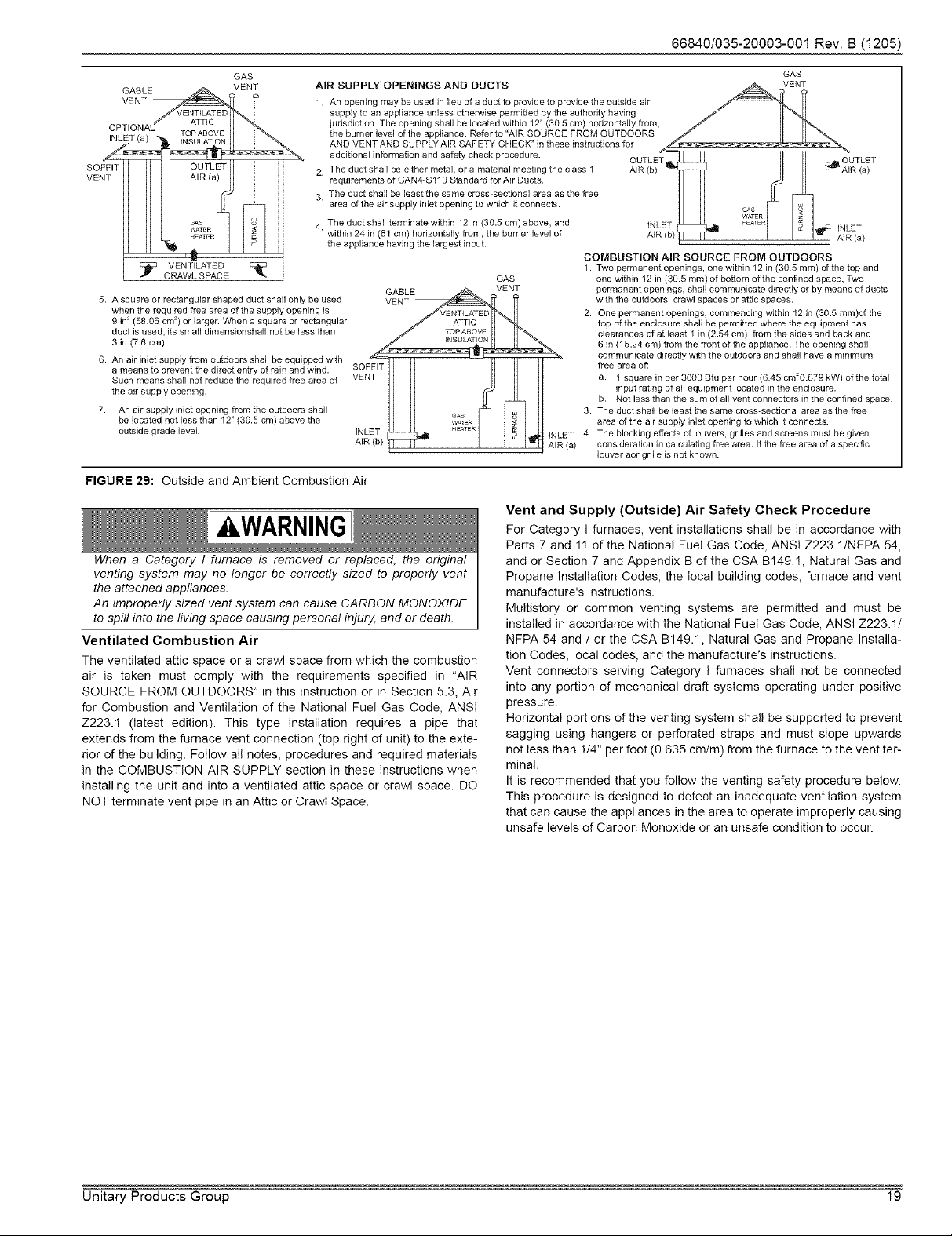
66840/035-20003-001Rev.B(1205)
GABLE VENT
OPTIONAL TOPABOVE
SOFFIT OUTLET
_:_ VENTILATED E_
CRAWL SPACE
when the required free area of the supply opening is 2.
9 in2(58•06 cm2) or larger• When a square or rectangular
duct is used, its small dimenstanshall not be less than
3 in (7•6 cm).
5. A square or rectangular shaped duct shall only be used vSO_ _
a means to prevent the direct entry of rain and wind•
Such means shall not reduce the required free area of
the air supply opening•
7. An air supply inlet opening from the outdoors shall 3.
be located not less than 12" (30•5 cm) above the _As
6. An att tiger supply fr td hall be equipped with _.... ..... _ _!
outside gradelevel• INLET H_TER NLET 4.
GAS
J
AIR SUPPLY OPENINGS AND DUCTS
1. An opening may be used in lieu of a duct to provide to provide the outside air
supply to an appliance unless otherwise permitted by the authority having
jurisdiction• The opening shah be located within 12" (30.5 cm) horizontally from,
the burner level of the appliance. Refer to "AIR SOURCE FROM OUTDOORS
AND VENT AND SUPPLY AIR SAFETY CHECK" in these instructions for
additional information and safety check procedure•
2. The duct shah be either metal, or a material meeting the class 1
requirements of CAN4-S110 Standard for Air Ducts•
3. The duct shah be ]east the same cross-sectional area as the free
area of the air supply inlet opening to which it connects.
4 The duct shah terminate within 12 in (30.5 cm) above, and
• within 24 in (61 cm) horizontally from, the burner ]eve] of
the appliance having the largest input•
GABLE VENT
AR b AIR(a)
GAS
WATER
FIGURE 29: Outside and Ambient Combustion Air
Vent and Supply (Outside) Air Safety Check Procedure
kWARNING
For Category I furnaces, vent installations shall be in accordance with
Parts 7 and 11 of the National Fuel Gas Code, ANSI Z223.1/NFPA 54,
When a Category I fumace is removed or replaced, the original
venting system may no longer be correctly sized to properly vent
the attached appliances.
An improperly sized vent system can cause CARBON MONOXIDE
to spill into the living space causing personal injury, and or death.
Ventilated Combustion Air
The ventilated attic space or a crawl space from which the combustion
air is taken must comply with the requirements specified in "AIR
SOURCE FROM OUTDOORS" in this instruction or in Section 5.3, Air
for Combustion and Ventilation of the National Fuel Gas Code, ANSI
Z223.1 (latest edition). This type installation requires a pipe that
extends from the furnace vent connection (top right of unit) to the exte-
rior of the building. Follow all notes, procedures and required materials
in the COMBUSTION AIR SUPPLY section in these instructions when
installing the unit and into a ventilated attic space or crawl space. DO
NOT terminate vent pipe in an Attic or Crawl Space.
and or Section 7 and Appendix B of the CSA B149.1, Natural Gas and
Propane Installation Codes, the local building codes, furnace and vent
manufacture's instructions.
Multistery or common venting systems are permitted and must be
installed in accordance with the National Fuel Gas Code, ANSI Z223.1/
NFPA 54 and / or the CSA B149.1, Natural Gas and Propane Installa-
tion Codes, local codes, and the manufacture's instructions.
Vent connectors serving Category I furnaces shall not be connected
into any portion of mechanical draft systems operating under positive
pressure•
Horizontal portions of the venting system shall be supported to prevent
sagging using hangers or perforated straps and must slope upwards
not less than !/4" per foot (0.635 cm/m) from the furnace to the vent ter-
minal.
It is recommended that you follow the venting safety procedure below•
This procedure is designed to detect an inadequate ventilation system
that can cause the appliances in the area to operate improperly causing
unsafe levels of Carbon Monoxide or an unsafe condition to occur.
GAS
VENT
AIR (b) AIR (a)
INLET
COMBUSTION AIR SOURCE FROM OUTDOORS
1. Two permanent openings, one within 12 in (30.5 ram) of the top and
one within 12 in (30.5 ram) of bottom of the confined space, Two
permanent openings, shall communicate directly or by means of ducts
with the outdoors, crawl spaces or attic spaces•
One permanent openings, commencing within 12 in (30.5 ram)of the
top of the enclosure shall be permitted where the equipment has
clearances of at least 1 in (2.54 cm) from the sides and back and
6 in (15.24 cm) from the front of the appliance. The opening shall
communicate directly with the outdoors and shall have a minimum
free area of:
a. 1 square in per 3000 Btu per hour (6.45 cm20.879 kW) of the total
input rating of all equipment located in the enclosure•
b. Not less than the sum of all vent connectors in the confined space•
The duct shall be least the same cross-sectional area as the free
area of the air supply inlet opening to which it connects•
The blocking effects of louvers, grilles and screens must be given
consideration in calculating free area. If the free area of a specific
louver act grille is not known•
WATER
HEATER INLET
,R/a)
Unitary Products Group 19
Page 20

66840/035-20003-001Rev.B(1205)
AWARNING
CARBON MONOXIDE POISONING HAZARD
Failure to follow the steps outlined below for each appliance connected to the venting system being placed into operation could result in carbon
monoxide poisoning or death.
The following steps shaft be followed for each appliance connected to the venting system being placed into operation, while all other appliances
connected to the venting system are not in operation:
1. Inspect the venting system for proper size and horizontal pitch. Determine that there is no blockage, restriction, leakage, corrosion or other
deficiencies, which could cause an unsafe condition
2. Close all building doors and windows and all doors.
3. Turn on clothes dryers and TURN ON any exhaust fans, such as range hoods and bathroom exhausts, so they shall operate at maximum
speed. Open the fireplace dampers. Do not operate a summer exhaust fan.
4. Follow the lighting instructions. Place the appliance being inspected in operation. Adjust thermostat so the appliance shall operate contin-
uously.
5. Test each appliance (such as a water heater) equipped with a draft hood for spillage (down-draft or no draft) at the draft hood relief opening
after 5 minutes of main burner operation. Appliances that do not have draft hoods need to be checked at the vent pipe as close to the
appliance as possible. Use a combustion analyzer to check the CO2 and CO levels of each appliance. Use a draft gauge to check for a
downdraft or inadequate draft condition.
6. After it has been determined that each appliance properly vents when tested as outlined above, return doors, windows, exhaust fans, fire-
place dampers and any other gas burning appliance to their normal condition.
7. If improper venting is observed during any of the above tests, a problem exists with either the venting system or the appliance does not
have enough combustion air (Supply Air from outside) to complete combustion. This condition must be corrected before the appliance can
function safely.
NOTE: An unsafe condition exists when the CO reading at the furnace vent exceeds 40 ppm and the draft reading is not in excess d - 0.1 in.
W.C. (-25 kPa) with all of the appliance(s) operating at the same time.
8. Any corrections to the venting system and / or to the supply (outside) air system must be in accordance with the National Fuel Gas Code
Z223.1 or CANICGA B149.1-00 Natural Gas and Propane Installation Code (latest editions). If the vent system must be resized, follow the
appropriate tables in Appendix G of the above codes or for this appliance.
SECTION Vllh SAFETY CONTROLS
CONTROL CIRCUIT FUSE
A 3-amp fuse is provided on the control circuit board to protect the 24-
volt transformer from overload caused by control circuit wiring errors.
This is an ATO 3, automotive type fuse and is located on the control
board.
BLOWER DOOR SAFETY SWITCH
This unit is equipped with an electricaI interlock switch mounted in the
blower compartment. This switch interrupts all power at the unit when
the panel covering the blower compartment is removed.
Electrical supply to this unit is dependent upon the panel that covers the
blower compartment being in place and properly positioned.
CAUTIONI
Main power to the unit must still be interrupted at the main power
disconnect switch before any service or repair work is to be done to
the unit. Do not rely uoon the interlock switch as a main oower dis-
connect.
Blower and burner must never be operated without the blower
panel in place.
ROLLOUT SWITCH CONTROLS
These controls are mounted on the burner box assembly. If the temper-
ature in the burner box exceeds its set point, the ignition control and the
gas valve are de-energized. The operation of this control indicates a
malfunction in the combustion air blower, heat exchanger or a blocked
vent pipe connection. Corrective action is required. These are manual
reset controls that must be reset before operation can continue.
PRESSURE SWITCHES
This furnace is supplied with a pressure switch, which monitors the flow
through the combustion air/vent piping system. This switch de-ener-
gizes the ignition control module and the gas valve if any of the follow-
ing conditions are present. Refer to Figure 30 for tubing connections.
1. Blockage of combustion air piping or terminal.
2. Blockage d vent piping or terminal.
3. Failure of combustion air blower motor.
FIGURE 30: Pressure Switch Tubing Routing
LIMIT CONTROLS
There is high temperature limit control located on the furnace vestibule
panel near the gas valve. This is an automatic reset control that pro-
vides over temperature protection due to reduced airflow, that may be
caused by a dirty filter, or if the indoor fan motor should fail. The control
module will lockout if the limit trips 3 consecutive times. Control will
reset and try ignition again after 1 hour.
SECTION IX: START-UP AND
ADJUSTMENTS
The initial start-up of the furnace requires the following additional
procedures:
IMPORTANT: All electrical connections made in the field and in the fac-
tory should be checked for proper tightness.
When the gas supply is initially connected to the furnace, the gas piping
may be full of air. In order to purge this air, it is recommended that the
ground union be loosened until the odor of gas is detected. When gas is
detected, immediately retighten the union and check for leaks. Allow
five minutes for any gas to dissipate before continuing with the start-up
procedure. Be sure proper ventilation is available to dilute and carry
away any vented gas.
20 Unitary Products Group
Page 21

TOOLS AND INFORMATION THAT WILL BE
REQUIRED IN ORDER TO PROPERLY PERFORM THE
FURNACE STARTUP PROCEDURE.
1. Call the local gas supplier to obtain heating value of the natural
gas. If you cannot obtain the heating valve of the gas from the gas
supplier, you may use a default value of 1030 BTU/SCF (38.8 MJ /
m3) for natural gas.
2. You will need a thermometer or portable digital thermometer to
read the supply and return air temperatures.
3. You will need a U-tube manometer or digital equipment that has
the ability to read pressures between 0 - 15" in.w.c (0 - 3.73 kPa)
in order to measure the gas line and the manifold pressures.
4. You will need a 3/32" Allen wrench for the pressure port plugs in
the gas valve.
5. You will need 2 pieces of 1/8" (0.3 cm) ID flexible tubing that is !2"
(30 cm) in length, 2 - pieces of 118" (0.3 cm) tubing that are 4"
(10.0 cm) in length, a 1/8" (0.3 cm) tee and a 1t8" (0.3 cm) adapter
to connect the U-tube manometer or the digital pressure measur-
ing equipment to the gas valve pressure ports.
There is an accessory kit (1PK0601) available from Source !, which
has the following items:
• 1 - 12" (30 cm) length x 1/8" (0.3 cm) diameter tubing
• 2 - pieces of 4" (10 cm) length x 1/8" (0.3 cm) diameter tubing
• 1 - 5/16" (0.8 cm) tee
• ! - 5/16" (0.8 cm) x 1/8" (0.3 cm) reducing coupling
• 1 - 1/8" (0.3 cm) adapter
There is a accessory kit (1PK0602) available from Source 1, which has
the following items:
!2" (30 cm) length x 1/8" (0.3 cm) diameter tubing
2 - pieces of 4" (10 cm) length x !/8" (0.3 cm) diameter tubing
1 - 5/16" (0.8 cm) tee
1 - 5/16" (0.8 cm) x 1/8" (0.3 cm) reducing coupling
! - 1/8" (0.3 cm) adapter
! - Dwyer - Manometer
These items are required in order to properly perform the required star-
tup procedure.
IGNITION SYSTEM SEQUENCE
1. Turn the gas supply ON at external valve and main gas valve.
2. Set the thermostat above room temperature to call for heat.
3. System start-up will occur as follows:
a. The induced draft blower motor will start and come up to
speed. Shortly after inducer start-up, the hot surface igniter
will glow for about 17 seconds.
b. After this warm up, the ignition module will energize (open)
the main gas valve.
c. After flame is established, the supply air blower will start in
about 30 seconds.
66840/035-20003-001Rev.B(1205)
_WARNING
FIRE OR EXPLOSION HAZARD
Failure to follow the safety warnings exactly could result in serious
injury, death or property damage.
Never test for gas leaks with an open flame. Use a commercially
available soap solution made specifically for the detection of leaks
to check al! connections. A fire or explosion may result causing
property damage, personal injury or loss of life.
IMPORTANT: Burner ignition may not be satisfactory on first startup
due to residual air in the gas line or until gas manifold pressure is
adjusted. The ignition control will make 3 attempts to light before lock-
ing out.
With furnace in operation, check all of the pipe joints, gas valve connec-
tions and manual valve connections for leakage using an approved gas
detector, a non-corrosive leak detection fluid, or other leak detection
methods. Take appropriate steps to stop any leak. If a leak persists,
replace the component.
The furnace and its equipment shutoff valve must be disconnected from
the gas supply piping system during any pressure testing of that system
at test pressures in excess of 1/2 PSI (3.45 kPa).
The furnace must be isolated from the gas supply piping system by
closing the equipment shutoff valve during any pressure testing of the
gas supply piping system.
CALCULATING THE FURNACE INPUT
(NATURAL GAS)
NOTE: Burner orifices are sized to provide proper input rate using natu-
ral gas with a heating value of 1030 BTU/Ft 3. If the heating
value of your gas is significantly different, it may be necessary to
replace the orifices.
1. Turn off all other gas appliances connected to the gas meter.
2. At the gas meter, measure the time (with a stop watch) it takes to
use 2 cubic ft. (0.0566 m3.) of gas.
3. Calculate the furnace input by using one of the following equa-
tions.
Unitary Products Group 21
Page 22

66840/035-20003-001Rev.B(1205)
In the USA use the following formula to calculate the furnace input,
For natural gas multiply the heat content of the gas BTU/SCF (or Default 1030 BTU/SCF, times 2 cubic ft. of gas measured at the gas meter, times a
barometric pressure and temperature correction factor of 0.960; times 3600, then divided by the time (in seconds) it took to measure 2 cubic ft. of gas
from the gas meter.
For propane (LP) gas multiply the heat content of the gas BTU/SCF (or Default 2500 BTU/SCF, times ! cubic ft. of gas measured at the gas meter,
times a barometric pressure and temperature correction factor of 0.960; times 3600, then divided by the time (In seconds) it took to measure ! cubic
ft. of gas from the gas meter.
The formula for US input calculation using a cubic foot gas meter:
BTU/f 3 x 2 cult x 0960 x 3600 BTUH/H
Seconds it took to measure the 2 cu.ft, of gas
NATURAL GAS INPUT CALCULATION
EXAMPLE:
Natural Gas
1030 x 2 x 0960 x 3600
905
BTU/SCF 1030
79,997.38
In Canada you will use the following formula to calculate the furnace input if you are using a cubic foot gas meter,
For Natural Gas multiply the Heat content of the gas MJ/m 3 (or Default 39.2), times 2 cu. ft. of gas x 0.02831 to convert from cubic feet to cubic
meters measured at the gas meter, times a barometric pressure and temperature correction factor of 0.960; times 3600, then divided by the time it
took to measure 2 cu.ft, of gas from the gas meter.
For Propane (LP) Gas multiply the Heat content of the gas MJim3 (or Default 93.14), times ! cu. ft. of gas x 0.02831 to convert from cubic feet to
cubic meters measured at the gas meter, times a barometric pressure and temperature correction factor of 0.960; times 3600, then divided by the
time it took to measure ! cu.ft, of gas from the gas meter.
The formula for metric input calculation using a cubic foot gas meter:
MJ/m 3 x (2 cu.ft, x Cony) x 0960 x 3600
Seconds it took to measure the 2 cu ft of gas
NATURAL GAS INPUT CALCULATION
EXAMPLE:
Natural Gas
PROPANE (LP) GAS INPUT CALCULATION
EXAMPLE:
Propane Gas
392 x 2 x 0.960 x 3600
90.5
BTU/SCF 1030 = 39.2 MJ/m 3
9315 x 1 x 0960 x 3600
108
BTU/SCF 2500+93 15 MJ/m 3
= MJ/H
= 8476
= 8441
I BTU/f 3 x 1 cu.ft, x 0.960 x 3600
Seconds it took to measure the 2 cuft of gas
PROPANE (LP) GAS INPUT CALCULATION
EXAMPLE:
2500 x 1 x 0960 x 3600
108
Propane Gas
BTU/SCF 2500
02777 kW x 3412.14 BTUH/H
02777 2354 x 3412.14 80,31262
02777 2345 x 3412.14 80,00000
= BTUH/H
= 80,00000
In Canada use the following formula to calculate the furnace input if you are using a gas meter that measures cubic meters.
For Natural Gas multiply the Heat content of the 3gas MJim (or Default 39.2), times 0.0566 m3 of gas measured at the gas meter, times a barometric
pressure and temperature correction factor of 0.960; times 3600, then divided by the time it took to measure 0.0566 m3 of gas from the gas meter.
For Propane (LP) Gas multiply the Heat content of the gas MJim 3 (or Default 93.14), times 0.00283 m3 of gas measured at the gas meter, times a
barometric pressure and temperature correction factor of 0.960; times 3600, then divided by the time it took to measure 0.0283 cm of gas from the
gas meter.
The formula for metric input calculation using a cubic foot gas meter:
MJ/m 3 x (2 cu.ft, x Cony) x 0960 x 3600
Seconds it took to measure the 2 cu ft of gas
NATURAL GAS INPUT CALCULATION
EXAMPLE:
Natural Gas
PROPANE (LP) GAS INPUT CALCULATION
EXAMPLE:
Propane Gas
392 x 2 x 0.960 x 3600
90.5
BTU/SCF 1030 = 39.2 MJ/m 3
9315 x 1 x 0960 x 3600
108
BTU/SCF 2580+93 15 MJ/m 3
= MJ/H
= 8476
= 8441
02777 kW x 3412.14 BTUH/H
02777 2354 x 3412.14 80,31262
02777 2345 x 3412.14 80,00000
DO NOT ADJUST the manifold pressure regulator if the actual input is equal to or within 8% less than the furnace input specified on the rating plate
or if the furnace rise is above the specified rise range on the rating plate.
If the actual input is significantly higher than the furnace input specified on the rating plate then replace the gas orifice spuds with the gas ori-
fice spuds of the proper size for the type of gas you are using.
For altitudes above 2,000 ft. (610 m) the furnace input MUST BE DERATED. Refer to the GAS CONVERSION FOR PROPANE (LP) AND HIGH
ALTITUDES IN SECTION IV for information on high altitude conversions.
22 Unitary Products Group
Page 23

[A CAUTION]
Be sure to relight any gas appliances that were turned off at the
start of this input check.
TABLE 14: Inlet Gas Pressure Range
INLET GAS PRESSURE RANGE
Natural Gas Propane(LP)
Minimum 45" WC (1 12 kPa) 80 _W.C (1 99 kPa)
Maximum 105 _W.C (261 kPa) 130" (3.24 kPa) W.C.
IMPORTANT: The inlet gas pressure operating range table specifies
what the minimum and maximum gas line pressures must be for the fur-
nace to operate safely. The gas line pressure MUST BE a minimum of
• 7"W.C. (1.74 kPA) for Natural Gas
• !1" W.C. (2.74 kPA) for Propane (LP) Gas
in order to obtain the BTU input specified on the rating plate and in
these instructions.
ADJUSTMENT OF MANIFOLD GAS PRESSURE
Manifold gas pressure may be measured at the gas valve.
Turn gas off at the ball valve or gas cock on gas supply line
before the gas valve. Find the pressure ports on the gas
valve marked OUT P and IN P.
1. The manifold pressure must be taken at the port marked OUT P.
2. The gas line pressure must be taken at the port marked IN P.
3. Using a 3/32" Allen wrench, loosen the setscrew by turning it 1
turn counter clockwise. DO NOT REMOVE THE SET SCREW
FROM THE PRESSURE PORT.
4. Use the 4" (10.2 cm) piece of 1/8" (0.3 cm) tubing to connect the
positive side of the manometer to the gas valve manifold pressure
port. Refer to Figure 32 for connection details.
IMPORTANT: The cap for the pressure regulator must be removed
entirely to gain access to the adjustment screw. Loosening or tightening
the cap does not adjust the flow of gas.
5. Refer to Figure 31 for location of pressure regulator adjustment
cap and adjustment screw on main gas valve.
6. Turn gas and electrical supplies on and follow the operating
instructions to place the unit back in operation.
7. Adjust manifold pressure by adjusting gas valve regulator screw
for the appropriate gas per the following:
TABLE 15: Nominal Manifold Pressure
NOMINAL MANIFOLD PRESSURE
Natural Gas 3.5" w.c. (0.87 kPa)
Propane (LP) Gas 10.0" wc (2488 kPa)
OUTLET
PRESSURE r_ _ Im
PORT _ I I
WRENCH J __
BOSS INLET_ _
PRESSURE
PORT
ON/OFF SWITCH
(Shown in OFF position)
ENT PORT
OUTLET
N REGULATOR
STMENT
66840/035-20003-001 Rev. B (1205)
IMPORTANT: If gas valve regulator is turned in (clockwise), manifold
pressure is increased. If screw is turned out (counterclockwise), mani-
fold pressure will decrease.
8. After the manifold pressure has been adjusted, re-calculate the
furnace input to make sure you have not exceeded the specified
input on the rating plate. Refer to "CALCULATING THE FURNACE
INPUT (NATURAL GAS)".
9. Once the correct BTU (kW) input has been established, turn the
gas valve to OFF and turn the electrical supply switch to OFF; then
remove the flexible tubing and fittings from the gas valve pressure
tap and tighten the pressure tap plug using the 3/32" Allen wrench.
10. Turn the electrical and gas supplies back on, and with the burners
in operation, check for gas leakage around the gas valve pressure
port for leakage using an approved gas detector, a non-corrosive
leak detection fluid, or other leak detection methods.
AWARNING
The manifold pressure must be checked with the screw-off cap for
the gas valve pressure regulator in place. If not, the manifold pres-
sure setting could result in an over-fire condition. A high manifold
pressure wil! cause an over-fire condition, which could cause pre-
mature heat exchanger failure. If the manifold pressure is too low,
sooting and eventual clogging of the heat exchanger could occur.
Be sure that gas valve regulator cap is in place and burner box to
gas valve pressure reference hose is connected.
MAINFOLD PRESSURE "U" TUBE CONNECTION
_j_llr_F_ / PRESSURE TAP
GASVALVE7 -_ MANIFOLDPIPE
_. / 1/4"TUBING
\ I_j,c._c _ WATER
FLAME U-TUBE I I_--_: COLUMN
SENSOR MANOMETER I I_--_: GAS
FIGURE 32: Reading Gas Pressure
ADJUSTMENT OF TEMPERATURE RISE
OUTLET
I_-- _-- PRESSURE
SHOWN
ADANGER
The temperature rise, or temperature difference between the return
air and the supply (heated) air from the furnace, must be within the
range shown on the fumace rating plate and within the application
limitations shown in Table 8 "ELECTRICAL AND PERFORMANCE
DATA".
The supply air temperature cannot exceed the "Maximum Supply
Air Temperature" specified in these instructions and on the fur-
nace rating plate. Under NO circumstances can the furnace be
allowed to operate above the Maximum Supply Air Temperature.
Operating the furnace above the Maximum Supply Air Temperature
wil! cause premature heat exchanger failure, high levels of Carbon
Monoxide, a fire hazard, personal inju04 property damage, and/or
death.
FIGURE 31: Gas Valve
Unitary Products Group 23
Page 24

66840/035-20003-001Rev.B(1205)
Thetemperaturerise,ortemperaturedifferencebetweenthereturnair
andtheheatedsupplyairfromthefurnace,mustbewithintherange
shownonthefurnaceratingplateandwithintheapplicationlimitations
asshowninTable8.
Afterabout15minutesofoperation,determinethefurnacetemperature
rise.Takereadingsofboththereturnairandtheheatedairintheducts,
aboutsixfeet(1.83m)fromthefurnacewheretheywillnotbeaffected
byradiantheat.Increasetheblowerspeedtodecreasethetemperature
rise;decreasetheblowerspeedtoincreasetherise.
Alldirect-driveblowershavemulti-speedmotors.Theblowermotor
speedtapsarelocatedinthecontrolboxintheblowercompartment.
RefertoFigure33,andtheunitwiringlabeltochangetheblower
speed.Tousethesamespeedtapforheatingandcooling,theheatter-
minalandcoolterminalmustbeconnectedusingajumperwireand
connectedtothedesiredmotorlead.Placeallunusedmotorleadson
Parkterminals.Twoareprovided.
CAUTION1
Do not energize more than one motor speed at a time or damage to
the motor wil! result.
ADJUSTMENT OF FAN CONTROL SETTINGS
This furnace is equipped with a time-on/time-off heating fan control. The
fan on delay is fixed at 30 seconds. The fan off delay has 4 settings (60,
90, 120 and !80 seconds). The fan off delay is factory set to 120 sec-
onds. The fan-off setting must be long enough to adequately cool the
furnace, but not so long that cold air is blown into the heated space. The
fan-off timing may be adjusted by positioning the jumper on two of the
four pins as shown in Figure 33.
TABLE 16: Filter Performance - Pressure Drop Inches W.C. and (kPa)
60
180
FIGURE 33: Typical Heat!Cool Speed Tap Connections
FILTER PERFORMANCE
The airflow capacity data published in Table 17 represents blower per-
formance WITHOUT filters. To determine the approximate blower per-
formance of the system, apply the filter drop value for the filter being
used or select an appropriate value from the Table 16.
The filter pressure drop values in Table 16 are typical values for the
type of filter listed and should only be used as a guideline. Actual pres-
sure drop ratings for each filter type vary between filter manufacturers.
Airflow Range Disposable Hogs Hair* Pleated
CFM Cm/m In3 m3 In3 I m3 inwc kPa inwc kPa inwc kPa inwc kPa inwc kPa
751 - 1000 21.27- 28.32 330 0.0054 0.05 0.0125 0.05 0.0125 0.2 0.0498
1001 - 1250 28.35- 35.40 330 0.0054 0.1 0.0249 0.1 0.0249 0.2 0.0498
0-750 0-21.24 230 0.0038 !li!_ 0.01 0.0025 i_lil_ 0.01 0.0025 i_Ii1_i_015 0.0374
1251 - 1500 35.42- 42.47 330 0.0054 0.1 0.0249 0.1 0.0249 0.25 0.0623
1501 - 1750 42.50- 49.55 380 0.0062 ............ 0.15 0.0374 0.14 0.0349 0.3 0.0747
1751-2000 49.58-56.63 380 0.0062 658 0.0108 0.19 0.0473 0.!1 0.0274 0.18 0.0448 0.! 0.0249 0.3 0.0747 0.!7 0.0423
2001 &Above 56.66&Above 463 0.0076 658 0.0108 0.!9 0.0473 0.11 0.0274 0.18 0.0448 0.1 0.0249 0.3 0.0747 0.17 0.0423
* Hogs Hair Filtersare the type supptied with furnace (if suppIied)
APPLYING FILTER PRESSURE DROP TO
DETERMINE SYSTEM AIRFLOW
To determine the approximate airflow of the unit with a filter in place, foI-
low the steps below:
1. Select the filter type.
2. Select the number of return air openings or calculate the return
opening size in square inches to determine the proper filter pres-
sure drop.
3. Determine the External System Static Pressure (ESP) without the
filter.
4. Select a filter pressure drop from the table based upon the number
of return air openings or return air opening size and add to the
ESP from Step 3 to determine the total system static.
5. If total system static matches a ESP value in the airflow table (i.e.
0.20 w.c. (50 Pa), 0.60 w.c. (150 Pa), etc.,) the system airflow cor-
responds to the intersection of the ESP column and Model/Blower
Speed row.
6. If the total system static falls between ESP values in the table (i.e.
0.58 w.c. (144 Pa), 0.75 w.c. (187 Pa), etc.), the static pressure
may be rounded to the nearest value in the table determining the
airflow using Step 5 or calculate the airflow by using the following
example.
Minimum Opening Size Filter Type
1 Opening 2 Openings 1 Opening 2 Openings 1 Opening 2 Openings 1 Opening 2 Openings
I
Example: For a 75,000 BTUH (21.98 kW) furnace with 2 return open-
ings and operating on high-speed blower, it is found that total system
static is 0.38" w.c. To determine the system airflow, complete the follow-
ing steps:
Obtain the airflow values at 0.30 w.c. (75 Pa) & 0.40 w.c. (99.6 Pa) ESR
Airflow @ 0.30": 1408 CFM (39.8 m3/min)
Airflow @ 0.40": 1343 CFM (38.0 m3/min)
Subtract the airflow @ 0.30 w.c. (75 Pa) from the airflow @ 0.40 w.c.
(99.6 Pa) to obtain airflow difference.
1343 - 1408 = -65 CFM (!.89 m3/min)
Subtract the total system static from 0.30 w.c. (75 Pa) and divide this
difference by the difference in ESP values in the table, 0.40 w.c.
(99.6 Pa) - 0.30 w.c. (75 Pa), to obtain a percentage.
(0.38- O.30) / (O.40- 0.3O) = O.8
Multiply percentage by airflow difference to obtain airflow reduction.
(O.8) X (-65) = -52
Subtract airflow reduction value to airflow @ 0.30 w.c. (75 Pa) to obtain
actual airflow @ 0.38 in wc (94.6 Pa) ESP.
1408 - 52 = 1356
24 Unitary Products Group
Page 25

66840/035-20003-001Rev.B(1205)
TABLE 17: Blower Performance - CFM
UPFLOW, SINGLE SIDE RETURN (WITHOUT FILTER)
BTU/H (kW) Cabinet Speed
Input/Output Size Tap 0.1 (0025) 0.2 (0050) 0.3 (0075) 0.4 (0099) 0.5 (0124) 0.6 (0149) 07 (0174) 0.8 (0199)
75/60 (22.0/176) I B Medium 1215 34.4 1199 34.0 1182 33.5 1151 32.6 1106 31.3 1039 29.4 976 27.6 887 25.1
75/60 (22.0/17.6) 11 C Medium 1597 45.2 1555 44.0 1496 42.4 1444 40.9 1372 38.9 1287 36.4 1190 33.7 1086 30.8
100/80(293/234) 2 C Medium 1602 45.4 1553 44.0 1503 42.6 1447 41.0 1376 39.8 1287 38.4 1181 33.4 1060 30.0
BTU/H (kW) Cabinet Speed
Input/Output Size Tap 0.1 (0025) 0.2 (0050) 0.3 (0075) 0.4 (0099) 0.5 (0124) 0.8 (0149) 07 (0174) 0.8 (0199)
75/60 (22.0/176) I B Medium 1243 35.2 1228 34.8 1214 34.4 1184 33.5 1133 32.1 1079 30.6 999 28.3 912 25.8
75/60 (22.0/176) I C Medium 1682 47.6 1657 46.9 1606 45.3 1530 43.3 1455 41.2 1366 38.7 1265 32.2 1137 32.2
100/80 (293/234) 2 C Medium 1667 47.2 1696 48.0 1656 46.9 1597 45.2 1523 43.1 1438 40.7 1330 37.7 1191 33.7
BTU/H (kW) Cabinet Speed
Input / Output Size Tap
75/60 (22.0/176) I B Medium 1229 34.8 1237 35.0 1198 33.9 1164 33.0 1105 31.3 1039 29.4 956 27.1 861 24.4
75/60(22.0/17.6) 11 C Medium 1683 47.7 1611 45.6 1551 43.9 1484 42.0 1388 39.3 1300 36.8 1190 33.7 1080 30.6
100/80 (293/234) 2 C Medium 1728 48.9 1679 47.5 1635 46.3 1556 44.1 1465 41.5 1359 38.5 1249 35.4 1117 31.6
1 Return air is through side opposite motor (left side).
2 Motor voltage at 115 V
Airflow expressed in standard cubic feet per minute (CFM) and in cubic meters per minute (m3/min)
TABLE 18: Field Installed Accessories - Non Electrical
MODEL NO. DESCRIPTION USED WITH
1NPOSO5 PROPANE (LP) CONVERSION KIT 50, 7512
1NPOS06 PROPANE (LP) CONVERSION KIT 7516, 10016
1LNOS02 LOW NOX KiT ALL MODELS
1FFO110 FILTER FRAME KIT 50, 7512
1FF0112 FILTER FRAME KiT 7516, 10016
1HAOS02 HiGH ALTITUDE iNSTRUCTION PACKET (DOES NOT iNCLUDE ORIFICES) ALL MODELS
TABLE 19: Field Installed Accessories - Electrical
MODEL NO. DESCRIPTION USED WITH
2TH07700124 THERMOSTAT-One-stage Heat, One-Stage CooI, with subbase ALL MODELS
2TH13700424 THERMOSTAT-One-stage Heat, One-Stage Cool ALL MODELS
2TB17700424 THERMOSTAT Subbase for 2TH13700424 ALL MODELS
2ET07700324 THERMOSTAT - Programmable ALL MODELS
2ET07700224 THERMOSTAT- Deluxe Programmable, One-stage Heat, One-stage Cool with subbase ALL MODELS
cfm cm/m cfm cm/m cfm cm/m cfm cm/m cfm cm/m cfm cm/m cfm cm/m cfm cm/m
High 1535 43.5 1470 41.6 1408 399 1343 38.0 1275 36.1 1202 34.0 1115 31.6 1014 28.7
Low 875 24.8 874 24.7 864 24.5 847 24.0 827 23.4 799 22.6 736 20.8 658 18.6
High 1792 50.7 1724 48.8 1630 462 1552 43.9 1462 41.4 1367 38.7 1264 35.8 1152 32.8
Low 1115 31.6 1140 32.3 1167 33.0 1183 33.5 1149 32.5 1093 31.0 1023 29.0 939 26.6
High 1888 52.9 1781 50.4 1690 479 1600 45.3 1498 42.4 1396 39.5 1277 36.2 1156 32.7
Low 1147 32.5 1147 32.5 1147 32.5 1147 32.5 1132 32.1 1078 30.5 1009 28.6 918 26.0
UPFLOW, DUEL RETURN, BOTTOM AND ONE SIDE OR TWO SIDE RETURN (WITHOUT FILTER)
HORIZONTAL APPLICATION BOTTOM RETURN (WITHOUT FILTER
cfm cm/m cfm cm/m cfm cm/m cfm cm/m cfm cm/m cfm cm/m cfm cm/m cfm cm/m
High 1634 48.3 1562 44.2 1484 420 1417 40.1 1340 37.9 1238 35.1 1154 32.7 1030 29.2
Low 886 25.1 886 25.1 886 25.1 886 25.1 865 24.5 823 23.3 777 22.0 700 19.8
High 1978 56.0 1896 53.7 1803 511 1693 47.9 1589 45.0 1478 41.9 1366 38.7 1235 35.8
Low 1235 35.0 1235 35.0 1235 35.0 1235 35.8 1198 33.9 1154 32.7 1083 30.7 987 27.9
High 2122 60.1 2027 57.4 1916 543 1821 51.6 1717 48.6 1590 45.0 1462 41.4 1312 37.2
Low 1130 32.0 1145 32.4 1177 33.3 1194 33.8 1181 33.4 1146 32.5 1077 30.5 982 27.8
BLOWER PERFORMANCE CFM - BOTTOM RETURN (WITHOUT FILTER)
0.1 (0025) 0.2 (0050) 0.3 (0075) 0.4 (0099) 0.5 (0124) 0.6 (0149) 07 (0174) 0.8 (0199)
cfm cm/m cfm cm/m cfm cm/m cfm cm/m cfm cm/m cfm cm/m cfm cm/m cfm cm/m
High 1552 43.9 1491 42.2 1420 402 1348 38.2 1271 36.0 1185 33.6 1080 30.6 970 27.5
Low 889 25.2 892 27.8 879 24.9 866 24.5 846 24.0 807 22.9 760 21.5 689 19.5
High 1946 55.1 1862 52.7 1775 503 1628 45.9 1518 43.0 1409 39.9 1291 36.6 1160 32.8
Low 1110 31.4 1138 32.2 1175 33.3 1190 33.7 1175 33.3 1126 31.9 1041 29.5 937 26.5
High 1997 56.5 1920 54.4 1822 516 1723 48.8 1620 45.9 1500 42.5 1355 38.4 1211 34.3
Low 1131 32.0 1156 32.7 1181 33.4 1190 33.7 1171 33.2 1126 31.9 1049 29.7 926 26.2
EXTERNAL STATIC PRESSURE, INCHES WC (kPa)
EXTERNAL STATIC PRESSURE, INCHES WC (kPa)
EXTERNAL STATIC PRESSURE, INCHES WC (kPa)
Unitary Products Group 25
Page 26

"11
C
m (. c SP I} "H,R/
CItART D VT SS
'ii]R CO OA KEY
(COD DE OOU ELR
[}U :: AGE]
........ s: ,< i R YH £J BRN BRO',_N
hC d,e . :
]: 2S"[ _ t :L mm
• i _ N) 4ROJ JA ] [8 ) i (VEAl VER]
:_ :_ us NO:_,/ i {] [ J ;IAL } i ',RO ) Jq8 ;TPRE; ( curt RE}
NOs , ROd, JAU 4 (8{ ', (BRU ', 8Rb )
-- ,,/ /
_ r ¸,
1]. D A "FW'b
/,c e AkC
{OR>_ ORAN E)
.... D7 ............. £Y
DZA ::,AMblE LEk N TDFRE
POt'ER SUPPLY i560 :E NOTE I
........................ t Y_ _ •
.... I feel ?_! v ¢> /_" <\ _>
c}- ._, yIIiTF,, r,r^T:oN _::s rs0 _r::< Nf£ 71 "
(REIAIS CHAUr/ L M) ,' motet ni )
(uo r r ix
r _,_ I AY ......_iq_[:_l..................
t J _]i k_2® i sN
ii -s_ .............. _ LAc _ EAC l
{ l TAE E (} _
, UM
,i : 7?: [j ................................................:(:F:,U'> :: .... i
,. ........ .V...:__;p<
I g_ (40,,A}
..........;:::;:;;E ] /®0 < y_>
i MOSM CL _!A/C IA I
l _} O F CATEUR _)i 41
.. ,H _ A:, Z / { ':N: {: k j
HE Y :' tM£ C4 JR) _'_ MOTEUR
i roe;\
RE AY Ul?d i xq._ ,[_ i
oN,A_" t AX ® '.-_> *-.........o •
COOL C4d l : _ J \ Y
AT/_O L T ENb_OSA
, .c) ...........................
0:i : r f ) i
ii:x k_]:,,/ ......................?
: 18N :
@ i i
stu
(_1EU]
Rrn
_bE
) Uses 3
RCS2 m:o :o:_: ROSI r_:[ rnt(
....iT{ti o _:i d(777(si;;ji
FI 4ME TEN! }7 _ GA_ 7AL_,E
{C_5 PT R _ (AZ_
F A,IldE) EL AJN)
ORt; Ob_,)
:U.+:7_ _ or'l+!::Z
x !
Lo)o _i ........
L r D {f )Uf )
)-::o i
i i {N TRn)
i N I RRE
i
pisSI 12 PIN PLUG a SOCKET ON :ON:lION CONV_OL BOA_O
P2/$2 ,_ PIN PLUO ¢ SOCk<El¸ ON IGNN:O_ CONtROl _OAr_D
P5/$3 2 PIN PLL:6 _ SOCK£1¸ AT _10_ SURFACE :GN:_Of_
P4/S_ ? PIN P_tJ8 & SOCKET AT :NOUCERMOTOR
f [] RELAY CONTACTS ON :6N:TION
LF: GEIx,D
:is iZS{X]NN:C: 9_I:cq
GV GAS VAL'_E
:G'_ HOT StJR:AC_ 18_ITE_
'SI P_IMAR{ t/Ml: SWIYCH
ROSl I_OLL OUT SW:fCI_ lOP LEFT
_OS_ ROll OUI S_ TCH _:M LEF_ (F68, GDC)
RO_5 :_C}Li OUT SWI:C:H • :S:_4 RiGHt (FG8 GDC)
,:lr_s Fbg.
i_P PR_StlAF S_:TCH _dRNER _DX/VENTOn
, TRANSFORMEA, _0',_
® :OEN:I_I:O r_UN_:,W'_,C:I:OR
Z_V CONN[:C:ION :_O0_d n_Er_UOSTAr
0 F/El 0 CONNEgI_ON
............................... f tRNAS S 5 _ONNE !(11 A M(O_I_
....... I-YeA ",U
.....................................................iX _ '17_4 _xJO_ _ D < ....
: _:_:<__ ,? :.................................w:+-_.........
.................................... 1@ ,? _7 C,) i
..........................................: "__ ,,o_
LEFT S:I)E (UOAA, UDA!_)
n:8_T S:OE (LJ_AA UGA_)
CONN (" ION (}],AGR'/,M
-- -- , L+_V, EI',ENi I AN PRE_ N SE:UI EVENI SUB IS
_LK Ii (fO 2 #AUT) i LTI /S JN MOT U _ 3 _R/N )
,, : ,, ,_: ONL_ C)N 5 (N URNACE
l _...... >,,/;:,: ,:; _N /' %7,7W2_,tt,:....
i f..............' .... v0] H_RYEIOU .... " yr : _.._/ :r:N vER:
i i I ,':::s:_r.E:U::<::::: l ,',[N_ i_ A_ i Y h _ _ ::_ i
o I : o:::£ :'< ;:7:':o: ::::_ L\ :
l l I W:l NE (_LA NEU} /./- ® _ GNO
i i • EN TEAAE
i i (F L ELEc)
I • ,'M:7 / OK '<foil IBVAC N
I : t : ,t, a A_c _,,c _Eu
i# A A ¢< (5L^'_C' i) J'tA
r1_ A C O T'_O l J_ ;i,> 7'o rTE e K No
g -q :_ \ - E
o o o o o s_ ..............
c _ ( :CN 0 5 ,,
l ...........T ........................................._H AN{} _LN: T:_N -
l ..... C B [ £ J ] gLMrTFI ('': b'L; ]
{k, - l] 2'Af!
(LAG [GRN MO /R
............................. v _T
i pa _
_- (*") ,>''% I E_ :E,_:_
j/_ ? i R
i}s CrMk4U:ArEtr :X [}ISJ[NC:)N
OV SOUPAPEOE G#Z
IGN :DN:::O_ DE SURFACE CHAtJOE
_i/SI P_:SE a RECEPTACLE A 12 PfS SUR LA _LAOUEI IE OE CONTAOLE O':GX:_ON
P2/$2 PF_SE t, r_ECEP?ACLE A ,_ P_S SUF_ LA PI AOUE_IE OE CONTF_OLE[Y/DN:TION
P5/$3 PR_SE E_¸ F_ECEPIACLE A 2 PTS 046N:TION DE SU_ ACE CHAUDE
P_/S_ PT_:SE :T AECEPT/_CLE A _ pTS At/ MDTEtJA O':NDUCT:ON
LSl COk_Mb_A_EUR OE tI_ I_ PR _CI_L_
ROSi CO_!U_A_EU_ OE ROULE_ENI¸ OESSUS 6AUCHE
0S2 cor,_k:UTA_EdR OE ROd_EMENT FONO G_UCHE _FGD, 88(:7
c_o f L_S:_tE
ILP COMVUT/_TEUADE PRES'>:OI'_:NCtlCT,BOIT_ DE BRUtE_;A
iR CAPASITE: R BE FONST:ONNE'_::NT IrJENTIF::
:T
l A:NSFORr,_EbR _.ow
® c_,A{:r::ur_D:: FON TIS:N[:M:N: X?EN::::E
24V RACCSRO:M:NT rX ::E:,OSh_r DE P:ECE
<,2 ACTOR MENI :'E <HANI:ER
...........: :cA3E BE L'US:NE E: Appt, R[:I:
FXAGE DE C ANTI:R ET APPARF: S
CONTA{T E RE A c ",( ..... {AQIE TE -' ONTROTE B73N ON
J
_SN
CO?E 8AUCHE _tJDA_,UDABJ
C8?E OROIT (bGAA d_A_)
CAU _-ON
OE ALl ?XCON£C _ 7 0"9
9ER', C:N( T S LN:T
80+ CLAM IUBE FU LACE
PREJCAU TZ()N
OU\R_} JES DISJONCTEURS MANT
o_: PROCEDER /VEC L: SER_'XX_
q i:o qi_ ........
NOTES:
A t F O WR:N8 - R: (A NA IONA LEC CODE { EC AND/OR/
2 Af 00[:OINA _I_ AS 6t S'LIEO _gT : _:PtNAC MUS B
HF'iAOD, :T Msr _ _[PI_CEO _H:! ,srqN{ MA_E AL IA'@:_G A
TE_IP RA U E RATN8 OF AT EAST 2 {0 C
5 tCI_N C ORS SUIABL foe COPPE :C)N LCS{JRS ONI Y
4 AL REPLACEVEN COkPON N S 'qJS BE P (P (Y ( OUN)ED
? PhOVIOE DISCONNECTS FOR A{ POAER SLPP 189
$ MOTORS #H£ : q:RENF Y p_OTECTE)
(B CA_AO_.N E EC COD (C C AND/OR/
{C LOCA ( C Y (OOES
NOTLS:
, TOUT I A c EN C AN cRS LON: {A) 88[? c EC NATONA{ CEN ET/O /
:: FX [o: f I_PI #( fq _ATR:E U OUT, l [30 r
I'[T' A'TE8 { w, Tr :AU> POU_ANT Pr ::S _, ?S T A_EfATJ!EB
O'AJ MOTN 2ZpF (i65_7)
3 EL Ere N' [ ,, VAR T S (',UR FI tzuv E
¢ out Ob'POSA !E }E M AElYEN O] [ rE E}EN M] E N ERR
FOLR_SS Z { s o o%c EURS POU 'A '¢EN A:TON
L MC s sgr: rRorrr:s [ rArq rLR _ N_ FTN
@', COO E C CANAD: N [CEC) ET/OU/
(() ,([8% i ;AUX E 17L_/ SAJX
035 i_ !5 O0i FE'V. _ (0/:04)
Page 27

NOTES
66840/035-20003-001 Rev. B (1205)
Unitary Products Group 27
Page 28

NOTES
Subject to change without notice. Printed in U.S.A.
Copyright st by York International Corp. 2005. All rights reserved.
Unitary
Product
Group
5OO5
York
Drive
66840/035-20003-001 Rev. B (1205)
Supersedes: 035-20003-001 Rev. A (0704)
Norman
OK
73069
 Loading...