

Page 1
TECHNICAL GUIDE
80% TWO STAGE VARIABLE SPEED ECM
MULTI-POSITION RESIDENTIAL
GAS FURNACES STANDARD & LOW NOx
MODELS: TM8V*C / TMLV*C
NATURAL GAS
60 - 120 MBH INPUT
Due to continuous product improvement, specifications are
subject to change without notice.
Visit us on the web at www.york.com
Additional rating information can be found at
www.ahridirectory.org
WARRANTY SUMMARY
A 20-year limited warranty on heat exchangers in residential applications.
A 10-year warranty on the heat exchanger in commercial
applications.
Standard 5-year limited Parts warranty.
Extended 10-year limited parts warranty when product
is registered online within 90 days of purchase for
replacement or closing for new home construction.
See Limited Warranty certificate in Users Informat ion Manual for details.
1071765-CTG-A-0913
DESCRIPTION
These compact units employ induced combustion, reliable hot
surface ignition and high heat transfer aluminized tubular heat
exchangers. The units are factory shipped for installation in
upflow or horizontal applications and may be converted for
downflow applications.
These furnaces are designed for residential installation in a
basement, closet, alcove, attic, recreation room or garage and
are also ideal for commercial applications. All units are factory
assembled, wired and tested to assure safe dependable and
economical installation and operation.
These units are Category I listed and may be common vented
with another gas appliance as allowed by the Nati onal Fuel Gas
Code.
FEATURES
• Two stage heating operation includes two stage gas valve,
two stage inducer operation and variable speed ECM blower
operation. Adjustable delay timer allows two stage operation
with a single stage thermostat.
• Easily applied in upflow, horizontal left or right, or downflow
installation with minimal conversion necessary .
• Compact, easy to install, ideal height 33" tall cabinet.
• ECM variable speed drive for cooling SEER enhancement,
improved comfort with optional airflow delay profiles, and
continuous fan options for IAQ performance.
• Easy access to controls to connect power/control wiring.
• Built-in, high level self diagnostics with fault code display.
• Low unit amp requirement for easy replacement application.
• All models are convertable to use propane (LP) gas.
• Electronic Hot Surface Ignition saves fuel cost with increased
dependability and reliability.
• 100% shut off main gas valve for extra safety.
• 24V, 40 VA control transformer and blower relay supplied for
add-on cooling.
• Hi-tech tubular aluminized steel primary heat exchanger.
• Solid removable bottom panel allows easy conversion.
• Airflow leakage less than 1% of nominal airflow for
ductblaster conditions.
• No knockouts to deal with, making installation easier.
• Movable duct connector flanges for application flexibility.
• Quiet inducer operation, burner, and blower operation.
• Inducer rotates for easy conversion of venting options.
• Fully supported blower assembly for easy access and
removal of blower.
• External air filters used for maximum flexibility in meeting
customers IAQ needs.
• Insulated blower compartment for thermal and acoustic
performance.
• Low NOx models have been designed to meet specific code
requirements.
• Venting applications - may be installed as a common vent
with other gas-fired appliances or use a masonry chimney.
• 1/4 turn knobs provided for easy independent door removal.
• These models may be connected as part of a communicating
control system using a 4-wire connection bus.
FOR DISTRIBUTION USE ONLY - NOT TO BE USED AT POINT OF RETAIL SALE
Page 2
1071765-CTG-A-0913
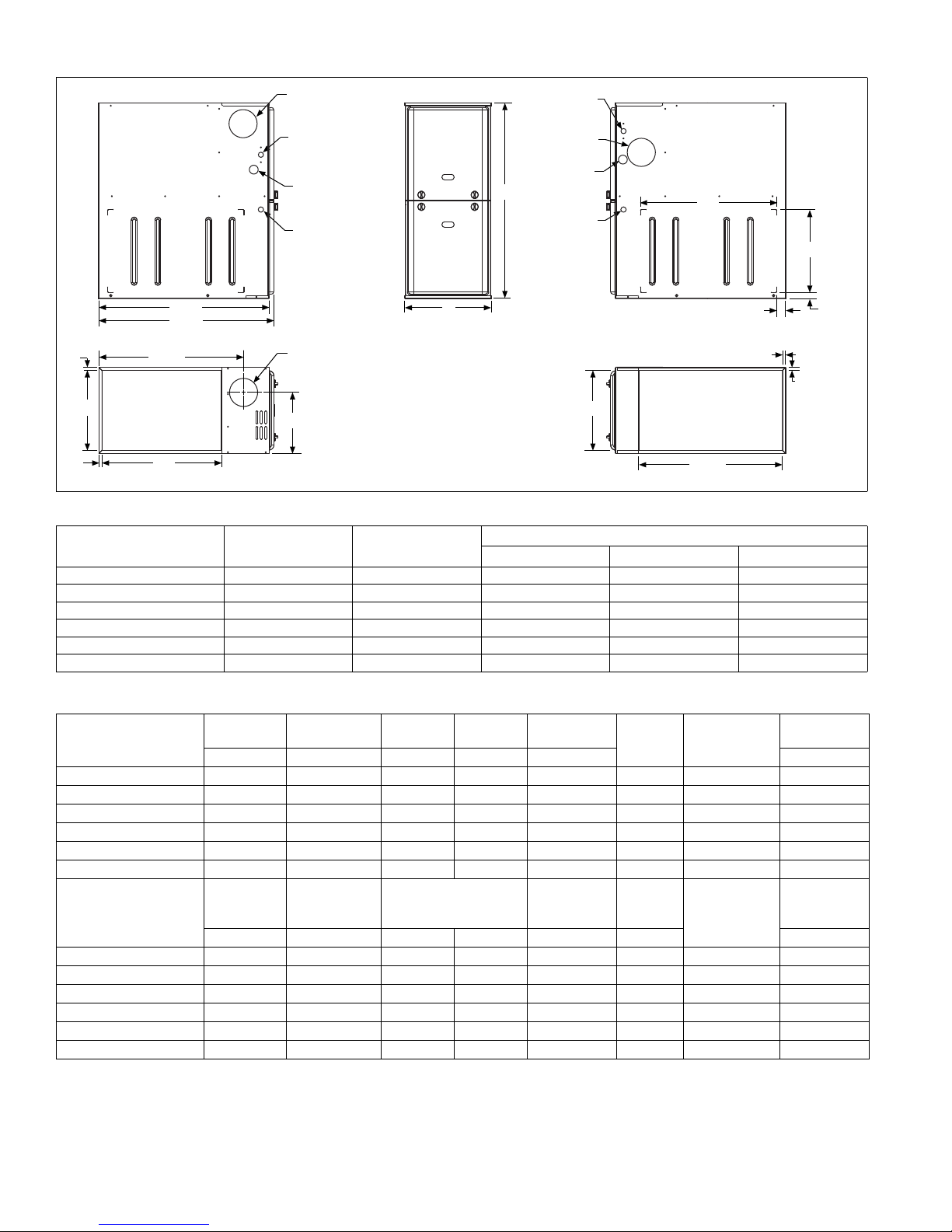
LEFT SIDE
RIGHT SIDE
.5”
.5”
RETURN END
B
24.25”
29.5”
28.5”
Electrical
Entry
Gas Pipe
Entry
Thermostat
Wiring
FRONT
14”
1”
1.5”
23”
SUPPLY END
C
24.38”
20”
.5”
B
Gas Pipe
Entry
Thermostat
Wiring
33”
A
.5”
Electrical
Entry
Vent Connection
Outlet
Vent
Connection
Outlet
4” Diameter
Outlet
Vent Connection
Cabinet & Duct Dimensions
Model
Nominal
CFM (m
3
/min)
Cabinet
Size
ABC
Cabinet Dimensions (Inches)
TM(8,L)V060A12MP11C 1200 A 14 1/2 13 3/8 10.3
TM(8,L)V080B12MP11C 1200 B 17 1/2 16 3/8 11.8
TM(8,L)V080C16MP11C 1600 C 21 19 7/8 13.6
TM(8,L)V100C16MP11C 1600 C 21 19 7/8 13.6
TM(8,L)V100C20MP11C 2000 C 21 19 7/8 13.6
TM(8,L)V120C20MP11C 2000 C 21 19 7/8 13.6
Table 1: Ratings & Physical / Electrical Data
High Fire
Models
Input
MBH MBH MBH MBH CFM °F
TM(8,L)V060A12MP11C 60 39 47 31 1200 9.0
TM(8,L)V080B12MP11C 80 52 63 42 1200 9.0
TM(8,L)V080C16MP11C 80 52 63 42 1600 12.0
TM(8,L)V100C16MP11C 100 65 80 52 1600 12.0
TM(8,L)V100C20MP11C 100 65 80 52 2000 14.0
TM(8,L)V120C20MP11C 120 78 96 62 2000 14.0
Models
High Fire
Air Temp.
Rise
°F °F HP Amps In. % Lbs.
TM(8,L)V060A12MP11C 30-60 15-45 1/2 7.7 11 x 8 80.0 14 94
TM(8,L)V080B12MP11C 30-60 20-50 1/2 7.7 11 x 8 80.0 14 103
TM(8,L)V080C16MP11C 30-60 20-50 3/4 9.6 11 x 10 80.0 14 114
Low Fire
Input
Low Fire
Air Temp. Rise
High Fire
Output
Blower
Low Fire
Output
Nominal
Airflow
Blower
Size
Total Unit
Amps
AFUE
Max.
Over-current
Protect
10
10
15
15
20
20
Min. wire Size
(awg) @ 75 ft
one way
Max. Outlet
Air Temp
Operating
weight
TM(8,L)V100C16MP11C 30-60 20-50 3/4 9.6 11 x 10 80.0 14 118
TM(8,L)V100C20MP11C 30-60 20-50 1 12.8 11 x 11 80.0 12 122
TM(8,L)V120C20MP11C 30-60 20-50 1 12.8 11 x 11 80.0 12 129
Annual Fuel Utilization Efficiency (AFUE) numbers are determined in accordance with DOE Test procedures.
Wire size and over current protection must comply with the National Electrical Code (NFPA-70-latest edition) and all local codes.
The furnace shall be installed so that the electrical components are protected from water.
160
160
160
160
160
160
2 Johnson Controls Unitary Products
Page 3

1071765-CTG-A-0913
NOTICE
HORIZONTAL SIDEWALL VENTING
For applications where vertical venting is not possible, the only
approved method of horizontal venting is the use of an auxiliary
power vent. Auxiliary power venters must be approved by CSA,
UL, or other recognized safety agencies. Follow all application
and installation details provided by the manufacturer of the
power vent.
FILTER PERFORMANCE
The airflow capacity data published in the “Blower Performance” table shown represents blower performance WITHOUT
filters.
All applications of these furnaces require the use of field
installed air filters. All filter media and mounting hardware or
provisions must be field installed external to the furnace cabinet. DO NOT attempt to install any filters inside the furnace.
Unit Clearances to Combustibles (All dimensions in inch es, and all surfaces identified with the unit in an up flow configuratio n )
Single side return above 1800 CFM is appro ved as long as
the filter velocity does not exceed filter manufacturer’s recommendation and a transition is used to allow use on a
20x25 filter.
Recommended Filter Sizes
CFM
1200 A 16 x 25 14 x 25
1200 B 16 x 25 16 x 25
1600 C 16 x 25 20 x 25
2000 C (2) 16 x 25 20 x 25
1. Air velocity through throwaway type filters may not exceed 300 feet per minute (91.4 m/min). All velocities over this require the use of high velocity filters.
2. Do not exceed 1800 CFM using a single side return and a 16x25 filter. For
CFM greater than 1800, you may use two side returns or one side and the
bottom or one return with a transition to allow use of a 20x25 filter.
Cabinet
Size
Side
(in)
Bottom
(in)
Application Top Front Rear
Upflow 1 1 0 0 0 6 Combustible Yes Yes Yes No
Upflow B-Vent 1 1 0 0 0 1 Combustible Yes Yes Yes No
Downflow 1 1 0 0 0 6
Downflow B-Vent 1 1 0 0 0 1
Horizontal 1 1 0 0 0 6 Combustible No Yes Yes
Horizontal B-Vent 1 1 0 0 0 1 Combustible No Yes Yes
1. Special floor base or air conditioning co il required for use on combustible floor.
2. Line contact only permitted between lines formed by the inter section of the rear p anel an d side p anel (top in hori zont al position) of th e furnace jacket and building joists, studs or framing.
Left
Side
ACCESSORIES
Propane (LP) Conversion Kit -
1NP0347 - All Models
This accessory conversion kit may be used to convert natural
gas units for propane (LP) operation.
Side Return Filter Racks -
1SR0200 - All Models
1SR0302 - All Models
1SF0101 - All Models
Bottom Return Filter Racks -
1BR0514 or 1BR0614 - For 14-1/2” cabinets
1BR0517 or 1BR0617 - For 17-1/2” cabinets
1BR0521 or 1BR0621 - For 21” cabinets
1BR05xx series are galvanized steel filter racks. 1BR06xx are
pre-painted steel filter racks to match the appearance of the furnace cabinet.
Masonry Chimney Kits -
1CK0603
1CK0604
Right
Side
Flue
Floor/
Bottom
1
1
1
1
Closet Alcove Attic
Yes Yes Yes No
Yes Yes Yes No
Line
Contact
Yes
Yes
Combustible Floor Base Kit -
For installation of these furnaces in downflow applications
directly onto combustible flooring material, These kits are
required to prevent potential overheating situations. These kits
are also required in any applications where the furnace in
installed in a downflow configuration without an evaporator coil,
where the combustible floor base kit provides access for combustible airflow.
1CB0514 - For 14-1/2” cabinets
1CB0517 - For 17-1/2” cabinets
1CB0521 - For 21” cabinets
High Altitude Pressure Switches -
For installation where the altitude is less than 5,000 feet it is not
required that the pressure switch be changed. For altitudes
above 5,000 feet, see kits below.
1PS3309
Thermostats - Compatible thermostat controls are available
through accessory sourcing. For optimum performance, these
indoor units are fully compatible with the Residential Touch-
screen Communicating Control S1-TTSCC01.
For installations where these furnaces are vented using existing
or new lined masonry chimneys.
2
2
Johnson Controls Unitary Products 3
Page 4

AIR FLOW DATA
HIGH / LOW SPEED COOLING AND HEAT PUMP CFM
TM(8,L)V060A12MP11C TM(8,L)V080B12MP11C Jumper Settings
High Low High Low COOL Tap ADJ Tap*
1309 851 1331 865 A B
1108 720 1090 708 B B
1190 774 1210 786 A A
1007 655 991 644 B A
1071 696 1089 708 A C
901 586 891 579 C B
906 589 892 580 B C
686 446 636 413 D B
819 532 810 526 C A
624 406 578 410 D A
737 479 729 474 C C
553 403 520 410 D C
TM(8,L)V080C16MP11C TM(8,L)V100C16MP11C Jumper Settings
High Low High Low COOL Tap ADJ Tap*
1794 1166 1765 1147 A B
1570 1020 1568 1019 B B
1631 1060 1605 1043 A A
1427 928 1425 926 B A
1468 954 1444 939 A C
1351 878 1331 865 C B
1284 835 1282 833 B C
1115 725 1086 706 D B
1228 798 1210 786 C A
1014 659 987 642 D A
1105 718 1089 708 C C
913 593 888 577 D C
TM(8,L)V100C20MP11C TM(8,L)V120C20MP11C Jumper Settings
High Low High Low COOL Tap ADJ Tap*
2230 1450 2200 1430 A B
1792 1165 1826 1187 B B
2030 1320 2065 1342 A A
1629 1059 1660 1079 B A
1827 1188 1858 1208 A C
1584 1030 1642 1067 C B
1466 953 1494 971 B C
1382 898 1401 911 D B
1440 936 1493 970 C A
1256 816 1274 828 D A
1296 842 1344 874 C C
1130 734 1147 746 D C
HIGH / LOW HEAT CFM
TM(8,L)V060A12MP11C TM(8,L)V080B12MP11C Jumper Settings
High Low High Low HEAT Tap ADJ Tap*
1111 963 1480 1284 A Any
988 825 1317 1100 B Any
889 722 1185 963 C Any
808 642 1077 856 D Any
TM(8,L)V080C16MP11C TM(8,L)V100C16MP11C Jumper Settings
High Low High Low HEAT Tap ADJ Tap*
1480 1289 1851 1604 A Any
1317 1100 1646 1375 B Any
1185 960 1481 1204 C Any
1077 855 1347 1070 D Any
TM(8,L)V100C20MP11C TM(8,L)V120C20MP11C Jumper Settings
High Low High Low HEAT Tap ADJ Tap*
1851 1604 2220 1925 A Any
1646 1375 1975 1651 B Any
1481 1204 1778 1444 C Any
1347 1070 1616 1284 D Any
All CFM’s are shown at 0.5” w.c. external static pressure.These units have variab le speed motors tha t automatically adju st to provide const ant CFM from 0.0” to 0.6” w.c.
static pressure. From 0.6” to 1.0” static pressure, CFM is reduced by 2% per 0.1” increase in static. Operation on duct systems with greater than 1.0” w.c. external static
pressure is not recommended.
NOTE: At some settings, LOW COOL and/or LOW HEAT airflow may be lower that what is required to operate an airflow switch o n cert a in mode ls of e lectro nic air cleaners. Consult the instructions for the electronic air cleaner for further det ails.
* The ADJ “D” tap should not be used.
Subject to change without notice. Published in U.S.A. 1071765-CTG-A-0913
Copyright © 2013 by Johnson Controls, Inc. All rights reserved. Supersedes: 523198-UTG-D-0513
York International Corp.
5005 York Drive
Norman, OK 73069
 Loading...