

Page 1
TECHNICAL GUIDE
95.5% SINGLE STAGE
GAS-FIRED RESIDENTIAL
MULTI-POSITION GAS FURNACES
MODELS: TG9S
NATURAL GAS
40 - 130 MBH INPUT
Due to continuous product improvement,
specifications are subject to change without notice.
Visit us on the web at www.york.com for the most
up-to-date technical information.
Additional efficiency rating information can
be found at www.gamanet.org.
EFFICIENCY
RATING
CERTIFIED
ISO 9001
Certified Quality
Management System
WARRANTY
Lifetime limited warranty on the heat exchanger.
10-year heat exchanger warranty on commercial applications.
5-year limited parts warranty.
FOR DISTRIBUTION USE ONLY - NOT TO BE USED AT POINT OF RETAIL SALE
400992-CTG-C-0209
DESCRIPTION
These compact units employ induced combustion, reliable hot
surface ignition and high heat transferaluminized tubular heat
exchangers. The units are factory shipped for installation in
upflow or horizontal applications and may be converted for
downflow applications.
These furnaces are designed for residential installation in a
basement, closet, alcove, attic, recreation room or garage and
are also ideal for commercial applications. All units are factory
assembled, wired and tested to assure safe dependable and
economical installation and operation.
These units are Category IV listed and may be vented either
through side wall or roof applications using approved plastic
combustion air and venr piping.
FEATURES
• Easily applied in upflow, horizontal left or right, or downflow
installation with minimal conversion necessary.
• Compact, easy to install, ideal height 33" tall cabinet.
• Blower-off delay for cooling SEER improvement.
• Easy access to controls to connect power/control wiring.
• Built-in, high level self diagnostics with fault code displays
standard on integrated control module for reliable
operation.
• Low unit amp requirement for easy replacement
application.
• Single wire twinning or staging feature available.
• All models are convertable to use propane (LP) gas.
• Electronic Hot Surface Ignition saves fuel cost with
increased dependability and reliability.
• 100% shut off main gas valve for extra safety.
• 4 speed, direct drive PSC motor.
• 24V, 40 VA control transformer and blower relay supplied
for add-on cooling.
• Hi-tech tubular aluminized steel primary heat exchanger.
• Secondary heat exchanger made of corrosion resistant
stainless steel materials.
• Timed on, adjustable off blower capability for maximum
comfort.
• Blower door safety switch.
• Solid removable bottom panel allows easy conversion.
• Airflow leakage less than 1% of nominal airflow at
ductblaster conditions.
• No knockouts to deal with, making installation easier.
• Movable duct connector flanges for application flexibility.
• Quiet inducer operation.
• Inducer rotates for easy conversion of venting options.
• Fully supported blower assembly for easy access and
removal of blower.
• External air filters used for maximum flexibility in meeting
customers IAQ needs.
• Protection included from air intake, exhaust vent, or
condensate blockage.
• Venting applications - may be installed as either 2-pipe
(sealed combustion) or single-pipe vent (using indoor
combustion air).
• No special vent termination required.
• 1/4 turn knobs provided for easy door removal.
• Internal condensate trap design (patent pe nding) provides
condensate management options, easy visual operation,
and is self-priming to prevent nuisance problems.
Page 2
400992-CTG-C-0209
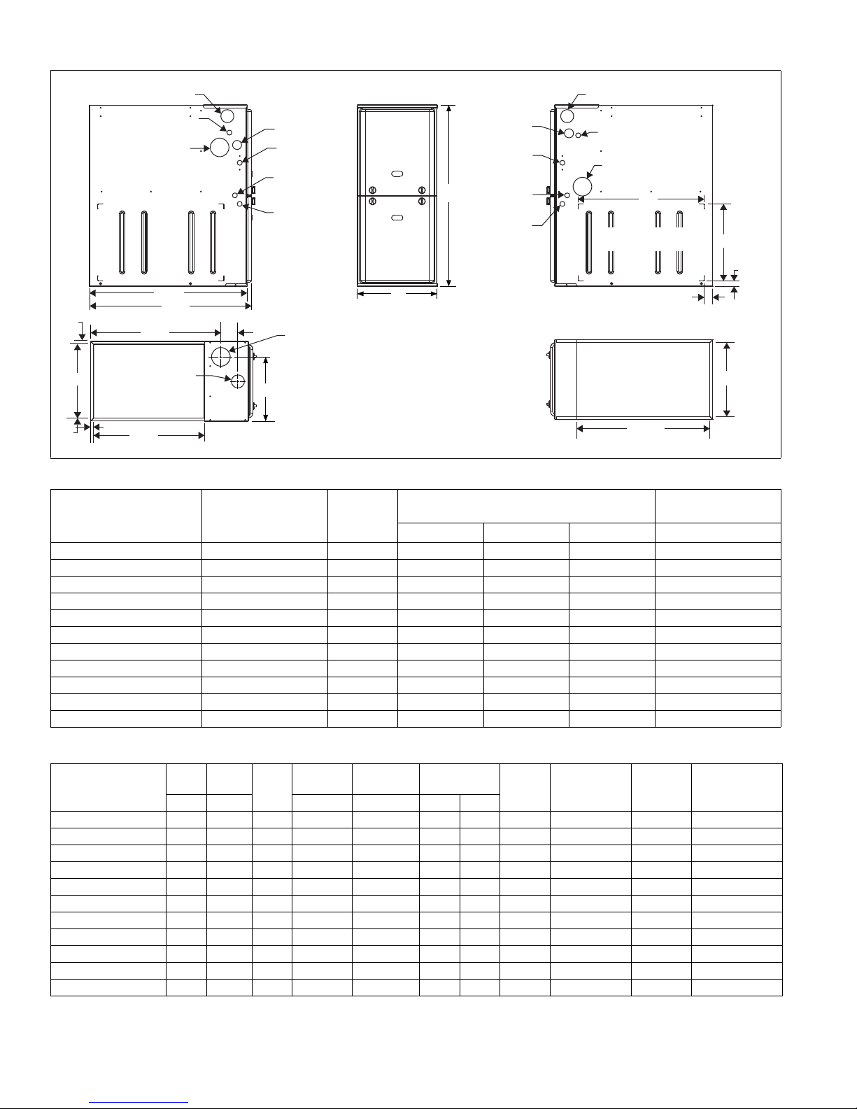
FRONT
33
A
LEFT SIDE
Combustion Air Inlet
Condensate Drain
(Downflow)
Vent Outlet
Thermostat
Wiring
28.5”
Gas Pipe
Entry
Electrical
Entry
Condensate
Drain
Thermostat
Wiring
RIGHT SIDE
Vent Outlet
Condensate Drain
(Downflow)
14”
1”
1.5”
23”
Combustion Air Inlet
Gas Pipe
Entry
Electrical
Entry
Condensate
Drain
Optional Return Air
Cutout (Either side)
29.5”
C
SUPPLY END
.56”
.56”
20”
B
3”
23.8”
.56”
Combustion
Air Inlet
Vent
Outlet
RETURN END
B
24.25”
Cabinet & Duct Dimensions
Models
Nominal
CFM (m
3
/min)
Cabinet
Size
Cabinet Dimensions (Inches)
ABC Lbs
TG9S040A08MP11 800 A 14 1/2 13 3/8 11 3/4 113
TG9S060A10MP11 1000 A 14 1/2 13 3/8 11 3/4 118
TG9S060B12MP11 1200 B 17 1/2 16 3/8 13 1/4 122
TG9S080B12MP11 1200 B 17 1/2 16 3/8 14 3/4 126
TG9S080C16MP11 1600 C 21 19 7/8 16 1/2 136
TG9S080C22MP11 2200 C 21 19 7/8 16 1/2 139
TG9S100C16MP11 1600 C 21 19 7/8 18 1/4 142
TG9S100C20MP11 2000 C 21 19 7/8 18 1/4 145
TG9S120D16MP11 1600 D 24 1/2 23 3/8 21 3/4 153
TG9S120D20MP11 2000 D 24 1/2 23 3/8 21 3/4 156
TG9S130D20MP11 2000 D 24 1/2 23 3/8 No Hole 160
Ratings & Physical / Electrical Data
Models
Input Output
MBH MBH °F °F HP Amps
TG9S040A08MP11 40 38 95.5 30-60 160 1/3 4.8 11x8 15 8.0 14
TG9S060A10MP11 60 57 95.5 30-60 160 1/2 7.1 11x8 15 10.0 14
TG9S060B12MP11 60 57 95.5 30-60 160 1/2 7.1 11x8 15 10.0 14
TG9S080B12MP11 80 76 95.5 35-65 165 1/2 7.1 11x8 15 10.0 14
TG9S080C16MP11 80 76 95.5 35-65 165 3/4 8.8 11x10 15 11.5 14
AFUE
%
Air Temp.
Rise
Max. Outlet
Air Temp
Blower
TG9S080C22MP11 80 76 95.5 35-65 165 1 14.5 11x11 20 17.0 12
Blower
Size
Max
Over-Current
Protect
Total Unit
TG9S100C16MP11 100 95 95.5 35-65 165 3/4 8.8 11x10 15 11.5 14
TG9S100C20MP11 100 95 95.5 35-65 165 1 14.5 11x11 20 17.0 12
TG9S120D16MP11 120 114 95.5 40-70 170 3/4 8.8 11x10 15 11.5 14
TG9S120D20MP11 120 114 95.5 35-65 165 1 14.5 11x11 20 17.0 12
TG9S130D20MP11 130 123.5 95.5 45-75 175 1 14.5 11x11 20 17.0 12
2 Johnson Controls Unitary Products
Annual Fuel Utilization Efficiency (AFUE) numbers are determined in accordance with DOE Test procedures.
Wire size and over current protection must comply with the National Electrical Code (NFPA-70-latest edition) and all local codes.
The furnace shall be installed so that the electrical components are protected from water.
Approximate
Operating Weights
Min. wire Size
Amps
(awg) @ 75 ft
one way
Page 3

400992-CTG-C-0209
FILTER PERFORMANCE
The airflow capacity data published in the “Blower Performance” table listed above represents blower performance
WITHOUT filters.
All applications of these furnaces require the use of field
installed air filters. All filter media and mounting hardware or
provisions must be field installed external to the furnace cabinet. DO NOT attempt to install any filters inside the furnace.
NOTE: Single side return above 1800 CFM is approved as long
as the filter velocity does not exceed filter manufacturer ’s recommendation and a transition is used to allow use on a 2 0x25
filter.
Recommended Filter Sizes (High velocity 600 FPM)
CFM
800 A 16 x 25 14 x 25
1000 A 16 x 25 14 x 25
1200 A 16 x 25 14 x 25
1200 B 16 x 25 16 x 25
1600 B 16 x 25 16 x 25
1600 C 16 x 25 20 x 25
2000 C (2) 16 x 25 20 x 25
2200 C (2) 16 x 25 20 x 25
2000 D (2) 16 x 25 22 x 25
NOTES:
1. Air velocity through throwaway type filters may not exceed 300 feet
per minute (91.4 m/min). All velocities over this require the use of
high velocity filters.
2. Do not exceed 1800 CFM using a single side return and a 16x25 filter. For CFM greater than 1800, yo u may use t wo si de ret urns or one
side and the bottom or one return with a transition to allow use of a
20x25 filter.
Cabinet
Size
Side
(in)
Bottom
(in)
Unit Clearances to Combustibles
Application Upflow Downflow Horizontal
Top 1" 0" 0"
Vent 0" 0" 0"
Rear 0" 0" 0"
Side 0" 0" 1"
Front* 0" 0" 0"
1
Floor Combustible
Closet Yes Yes Yes
Line Contact No No Yes
1. For combustible floors only when used with special sub-base.
* - 24" clearance in front and 18" on side recommended for service access.
All furnaces approved for alcove and attic installation.
Combustible
Combustible
ACCESSORIES
PROPANE (LP) CONVERSION KIT -
S1-1NP0347 - All Models except 130K Model
S1-1NP0501 - 130K Model
This accessory conversion kit may be used to convert natural
gas (N) units for propane (LP) operation.
CONCENTRIC VENT TERMINATION -
S1-1CT0302 (2") & S1-1CT0302-636 (2")
S1-1CT0303 (3") & S1-1CT0303-636 (3")
For use through rooftop, sidewall. Allows combustion air to
enter and exhaust to exit through single common hole. Eliminates unslightly elbows for a cleaner installation.
SIDEWALL VENT TERMINATION KIT -
S1-1HT0901 (3")
S1-1HT0902 (2")
For use on sidewall, two-pipe installations only. Provide a more
attractive termination for locations where the terminal is visable
on the side of the home.
CONDENSATE NEUTRALIZER KIT - 1NK0301
Neutralizer cartridge has a 1/2" plastic tube fittings for installation in the drain line. Calcium carbonate refill media is also
available from the Source 1 Parts (p/n 026-30228-000).
SIDE RETURN FILTER RACKS -
S1-1SR0200 - All Models
S1-1SR0402 - All Models
BOTTOM RETURN FILTER RACKS -
S1-1BR0514 or 1BR0614 - For 14-1/2” cabinets
S1-1BR0517 or 1BR0617 - For 17-1/2” cabinets
S1-1BR0521 or 1BR0621 - For 21” cabinets
S1-1BR0524 or 1BR0624 - For 24-1/2” cabinets
1BR05xx series are galvanized steel filter racks. 1BR06xx are
pre-painted steel filter racks to match the appearance of the furnace cabinet.
COMBUSTIBLE FLOOR BASE KIT -
For installation of these furnaces in downflow applications
directly onto combustible flooring material, These kits are
required to prevent potential overheating situations.tible floor
base kit provides access for combustible airflow.
S1-1CB0514 - For 14-1/2” cabinets
S1-1CB0517 - For 17-1/2” cabinets
S1-1CB0521 - For 21” cabinets
S1-1CB0524 - For 24-1/2” cabinets
EAC TRANSITION KITS -
For installation of EAC accessories with these furnaces to provide easy transition of return airflow through the EAC to get the
proper sealing and reduced airflow leakage.
S1-1TK1001 - For all models using side return
S1-1TK1014 - For 14-1/2” cabinets using bottom return
S1-1TK1017 - For 17-1/2” cabinets using bottom return
S1-1TK1021 - For 21” cabinets using bottom return
S1-1TK1024 - For 24-1/2” cabinets using bottom return
HIGH ALTITUDE PRESSURE SWITCHES -
For installation where the altitude is less than 5,000 feet it is not
required that the pressure switch be changed. For altitudes
above 5,000 feet, see kits below.
S1-1PS3306 - 040, 080
S1-1PS3307 - 060
S1-1PS3302 - 100, 120, 130
ROOM THERMOSTATS - A wide selection of compatible thermosets are available to provide optimum performance and features for any installation.
1H/1C, manual change-over electronic non-programmable thermostat.
1H/1C, auto/manual changeover, electronic programmable,
deluxe 7-day, thermostat.
1H/1C, auto/manual changeover, electronic programmable.
* For the most current accessory information, refer to the price
book or consult factory.
Johnson Controls Unitary Products 3
Page 4

400992-CTG-C-0209
Blower Performance CFM - Any Position (without filter) - Bottom Return
Bottom Airflow Data (SCFM)
Models Speed
0.1 0.2 0.3 0.4 0.5 0.6 0.7 0.8 0.9 1.0
High 1128 1077 1035 996 950 891 842 781 708 646
TG9S040A08MP11
Medium High 934 909 867 834 818 780 745 696 631 584
Medium Low 746 735 714 679 653 629 596 585 547 494
Low 676 652 627 601 581 542 516 474 441 383
High 1360 1290 1230 1165 1103 1043 983 925 820 776
TG9S060A10MP11
Medium High 1251 1198 1140 1089 1038 979 916 854 790 718
Medium Low 1081 1062 1015 964 917 871 819 767 710 634
Low 909 900 852 812 769 739 712 662 612 547
High 1492 1442 1378 1325 1243 1176 1075 966 849 655
TG9S060B12MP11
Medium High 1236 1201 1161 1139 1082 1011 919 830 715 590
Medium Low 986 950 961 916 872 831 757 703 600 510
Low 824 795 783 744 713 659 624 554 489 389
High 1597 1537 1484 1435 1370 1286 1230 1155 1075 925
TG9S080B12MP11
Medium High 1338 1307 1273 1223 1179 1123 1065 998 928 812
Medium Low 1113 1094 1077 1043 1008 972 924 868 803 798
Low 937 916 900 877 854 817 775 718 639 560
High 1919 1865 1802 1738 1671 1600 1517 1414 1322 1201
TG9S080C16MP11
Medium High 1532 1533 1513 1499 1465 1416 1352 1283 1198 1084
Medium Low 1232 1313 1291 1280 1250 1209 1207 1148 1055 937
Low 826 821 853 858 838 817 794 776 760 711
High 2529 2435 2338 2256 2162 2041 1920 1794 1654 1501
TG9S080C22MP11
Medium High 2166 2111 2070 2001 1927 1849 1719 1614 1499 1344
Medium Low 1697 1685 1664 1631 1586 1531 1466 1393 1315 1185
Low 1383 1377 1358 1336 1285 1244 1199 1147 1048 925
High 1909 1880 1823 1776 1706 1637 1562 1474 1375 1252
TG9S100C16MP11
Medium High 1465 1463 1469 1485 1477 1416 1386 1324 1250 1114
Medium 1190 1222 1216 1215 1224 1189 1158 1145 1087 996
Low 787 834 819 836 819 810 790 761 690 707
High 2284 2205 2114 2021 1934 1848 1752 1653 1505 1397
TG9S100C20MP11
Medium High 1967 1905 1824 1763 1712 1628 1551 1473 1379 1213
Medium Low 1610 1563 1513 1480 1430 1367 1319 1261 1101 1012
Low 1326 1304 1267 1232 1183 1143 1080 1003 871 798
High 2020 1994 1958 1878 1805 1740 1647 1560 1445 1294
TG9S120D16MP11
Medium High 1551 1559 1549 1520 1494 1451 1383 1334 1253 1145
Medium Low 1270 1267 1269 1269 1254 1227 1185 1121 1051 985
Low 932 916 905 894 876 828 803 725 754 696
High 2341 2245 2153 2072 1977 1876 1769 1642 1506 1306
TG9S120D20MP11
Medium High 2002 1952 1878 1823 1739 1657 1563 1458 1322 1185
Medium Low 1615 1579 1533 1473 1430 1368 1282 1186 1091 953
Low 1352 1295 1259 1245 1190 1141 1076 998 938 820
High 2412 2329 2247 2173 2047 1980 1887 1777 1655 1511
TG9S130D20MP11
Medium High 2040 2004 1948 1876 1786 1738 1656 1562 1461 1314
Medium Low 1614 1591 1549 1531 1459 1400 1335 1267 1180 1061
Low 1327 1294 1257 1224 1198 1171 1124 1036 944 848
NOTES:
1. Airflow expressed in standard cubic feet per minute (CFM).
2. Motor voltage at 115 V.
Ext. Static Pressure (in. H2O)
4 Johnson Controls Unitary Products
Page 5

Blower Performance CFM - Any Position (without filter) - Left Side Return
Left Side Airflow Data (SCFM)
Models Speed
0.1 0.2 0.3 0.4 0.5 0.6 0.7 0.8 0.9 1.0
High 1131 1091 1053 1003 965 921 862 800 733 659
TG9S040A08MP11
Medium High 982 959 935 887 846 795 745 675 628 595
Medium Low 772 736 715 689 661 642 599 568 531 493
Low 636 618 585 569 546 522 486 460 455 370
High 1431 1375 1304 1244 1178 1109 1040 963 861 805
TG9S060A10MP11
Medium High 1280 1226 1171 1117 1059 1004 930 865 781 731
Medium Low 1099 1050 1008 970 919 866 814 759 710 626
Low 914 876 842 812 770 728 694 661 612 545
High 1470 1406 1361 1309 1241 1155 1060 920 775 628
TG9S060B12MP11
Medium High 1211 1186 1139 1101 1042 980 896 796 681 545
Medium Low 970 957 927 889 853 796 745 660 568 450
Low 793 781 756 724 694 653 585 530 469 382
High 1605 1562 1514 1454 1393 1330 1251 1169 1073 940
TG9S080B12MP11
Medium High 1372 1318 1280 1255 1205 1161 1093 1023 943 849
Medium Low 1087 1073 1052 1003 993 953 897 843 775 709
Low 916 896 881 854 831 802 757 708 642 574
High 1956 1907 1846 1778 1717 1647 1573 1483 1353 1209
TG9S080C16MP11
Medium High 1543 1543 1516 1504 1477 1446 1382 1309 1202 1099
Medium Low 1238 1241 1243 1241 1252 1242 1201 1140 1074 967
Low 906 902 903 910 888 866 859 829 795 743
High 2585 2492 2405 2321 2232 2137 2015 1902 1745 1577
TG9S080C22MP11
Medium High 2098 2067 2036 1982 1928 1860 1767 1670 1549 1331
Medium Low 1619 1628 1614 1584 1545 1488 1424 1339 1216 1121
Low 1338 1347 1327 1301 1262 1199 1138 1078 1019 938
High 1828 1829 1789 1768 1727 1671 1601 1505 1390 1272
TG9S100C16MP11
Medium High 1422 1444 1437 1424 1396 1326 1301 1253 1200 1100
Medium 1224 1229 1243 1234 1219 1193 1168 1135 1088 977
Low 813 819 818 814 783 762 756 732 690 642
High 2391 2286 2165 2079 2004 1934 1839 1692 1560 1366
TG9S100C20MP11
Medium High 1945 1878 1838 1782 1694 1642 1565 1451 1334 1163
Medium Low 1549 1530 1495 1430 1431 1365 1284 1192 1097 1022
Low 1256 1229 1189 1159 1089 1033 1008 950 871 784
High 1998 1987 1914 1858 1798 1721 1629 1530 1417 1303
TG9S120D16MP11
Medium High 1512 1506 1492 1467 1441 1406 1342 1280 1206 1097
Medium Low 1217 1219 1210 1185 1174 1148 1112 1063 1012 937
Low 892 870 859 843 814 798 790 745 740 677
High 2343 2253 2167 2071 1979 1881 1785 1668 1473 1351
TG9S120D20MP11
Medium High 1954 1892 1846 1781 1714 1637 1548 1429 1238 1171
Medium Low 1596 1539 1511 1458 1399 1341 1254 1180 942 988
Low 1299 1261 1229 1177 1111 1053 993 937 882 782
High 2425 2336 2255 2157 2046 1966 1865 1758 1615 1420
TG9S130D20MP11
Medium High 1979 1959 1899 1825 1773 1686 1619 1516 1376 1225
Medium Low 1582 1567 1540 1488 1443 1406 1336 1252 1146 1033
Low 1305 1287 1239 1194 1159 1126 1062 1003 943 831
NOTES:
1. Airflow expressed in standard cubic feet per minute (CFM).
2. Return air is through side opposite motor (left side).
3. Motor voltage at 115 V.
4. Airflow through across motor side (right side) may be slightly less than the data shown above.
Ext. Static Pressure (in. H2O)
400992-CTG-C-0209
Johnson Controls Unitary Products 5
Page 6

NOTES
Subject to change without notice. Printed in U.S.A. 400992-CTG-C-0209
Copyright © 2009 by Johnson Controls, Inc. All rights reserved. Supersedes: 400992-CTG-B-0708
Johnson Controls Unitary Products
5005 York Drive
Norman, OK 73069
 Loading...