

Page 1
TECHNICAL GUIDE
SPLIT-SYSTEM
AIR CONDITIONERS
14.5 SEER – R-410A
MODELS:
TCGF18 THRU 60
(1.5 THRU 5 NOMINAL TONS, 1 PHASE)
Due to continuous product improvement, specifications are
subject to change without notice.
Visit us on the web at
www.upgnet.com and www.colemanac.com
Additional rating information can be found at
www.ahridirectory.org
WARRANTY SUMMARY*
Standard 5-years limited parts warranty.
Standard 10-years limited compressor warranty.
Extended 10-years limited parts warranty when product is
registered online within 90 days of purchase for replacement
or closing for new home construction.
*Does not apply to R-22 models, 3-Phase models, or internet sales.
See Limited Warranty certificate in User's Information Manual for details.
®
700700-CTG-A-0312
DESCRIPTION
The 14.5 SEER Series unit is the outdoor part of a versatile climate system. It is designed with a matching indoor coil component from Johnson Controls Unitary Products. Available for
typical applications this climate system is supported with accessories and documents to serve specific functions.
FEATURES
• Small Footprint - Extremely lightweight with a compact foot-
print, it is a perfect fit for any application.
• Quality Condenser Coils - The coil is constru cted of aluminum microchannel tubing and enhanced aluminum fins for
reduced size and increased efficiency.
• Coil Protection - Coils are protected from damage by
a sturdy polymer mesh and a coated steel wire coil guard.
®
• Optional Factory E-Coat - Available ElectroFin
on select models.
• Protected Compressor - Compressors are protected internally by a high pressure relief valve and a temperature sensor, and externally by the system high pressure switch. A
factory installed liquid line filter-drier further protects the compressor against moisture and debris.
• Durable Finish - The cabinet is made of pre-painted steel.
The pre-treated galvanized steel provides a better paint-tosteel bond, which resists corrosion and rust creep. Special
primer formulas and matted-textured finish insure less fading
when exposed to sunlight.
• Lower Installed Cost - Installation time and costs are
reduced by easy power and control wiring connections.
Available in sweat connect models only. The unit contains
enough refrigerant for matching indoor coils and 15 feet of
interconnecting piping. The small base dimension means
less space is required on the ground or roof.
• Top Discharge - The warm air from the top mounted fan is
blown up, away from the structure and any landscaping. This
allows compact location on multi-unit applications.
• Competitive Sound Levels - The upward air flow carries the
normal operating noise away from the living area. The rigid
top panel effectively isolates any motor sound. Isolator
mounted compressor and the condenser coil muffle the normal fan motor and compressor operating sounds.
• Low Maintenance - Long life, permanently lubricated motorbearings need no annual servicing.
• Easy Service Access - Fully exposed refrigerant connections and a single panel covering the electrical controls make
for easy servicing of the unit.
• Secured Service Valves - Secured, re-usable service
valves are provided on both the liquid and vapor swe at connections for ease of evacuating and charging.
• Agency Listed - Safety certified by CSA to UL 1995 / CSA
22.2. Performance certified to ANSI/AHRI Standard 210/240
in accordance with the Unitary Small Equipment certification
program.
coated coil
FOR DISTRIBUTION USE ONLY - NOT TO BE USED AT POINT OF RETAIL SALE
Page 2
700700-CTG-A-0312
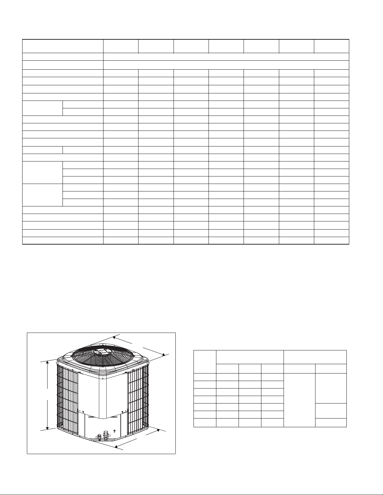
B
A
C
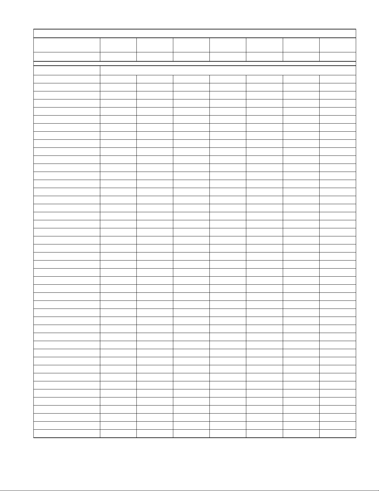
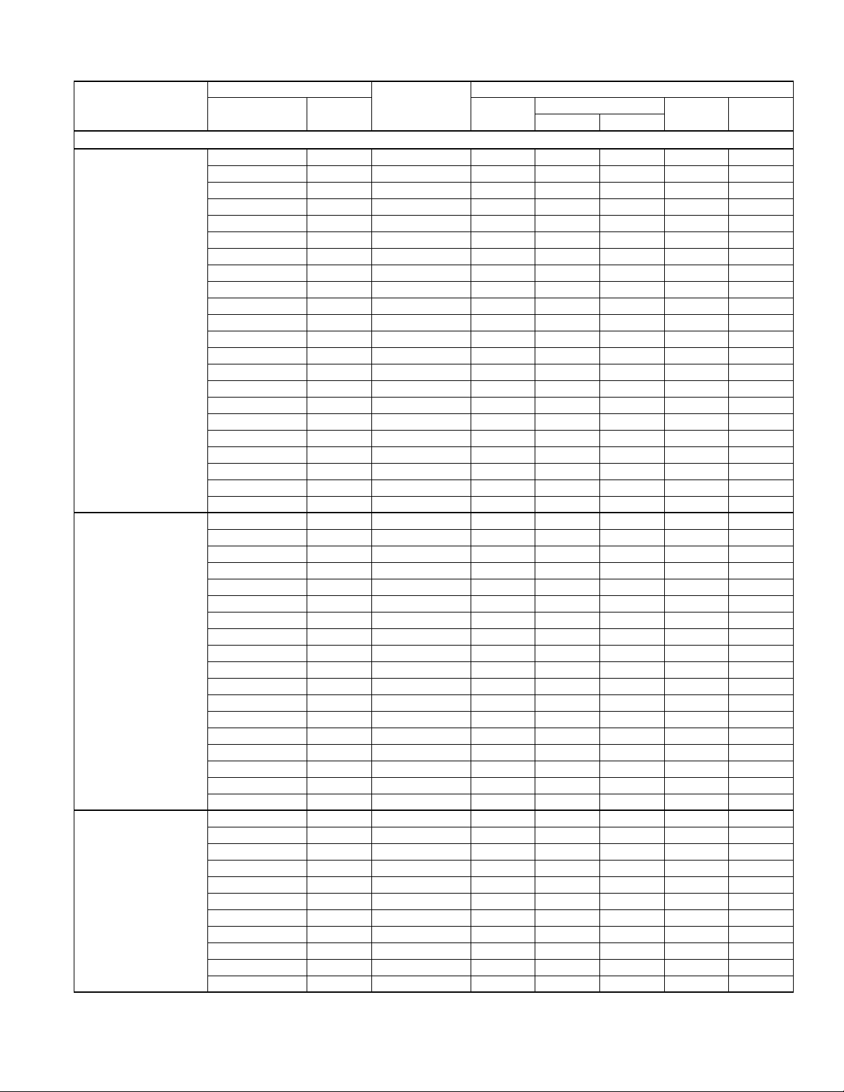
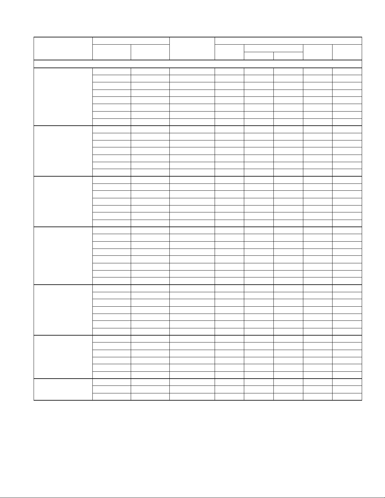
Physical and Electrical Data
MODEL
TCGF18
S41S3(E)
Unit Supply Voltage 208-230V, 1 60Hz
Normal Voltage Range
Minimum Circuit Ampacity
Max. Overcurrent Device Amps
Min. Overcurrent Device Amps
Compressor Type
Compressor
Amps
Crankcase Heater
Factory External Discharge Muffler
Factory External Check Valve
HS Kit Required with TXV
Fan Motor Amps Rated Load
Fan Diameter Inches
Fan Motor
Coil
Liquid Line Set OD (Field Installed)
Vapor Line Set OD (Field Installed)
Unit Charge (Lbs. - Oz.)
Charge Per Foot, Oz.
Operating Weight Lbs.
1
2
3
Rated Load
Locked Rotor
4
Rated HP
Nominal RPM
Nominal CFM
Face Area Sq. Ft.
Rows Deep
Fin / Inches
5
12.0 16.8 18.4 19.1 23.9 27.9 35.9
20 25 30 30 40 45 60
15 20 20 20 25 30 40
Scroll Scroll Scroll Scroll Scroll Scroll Scroll
9.0 12.8 14.1 14.1 17.9 21.1 27.5
46 58 73 77 112 115 135
No No No No No No No
No No No No No No No
No No No No No No No
No No No No No No No
0.8 0.8 0.8 1.5 1.5 1.5 1.5
22 22 22 22 24 24 24
1/8 1/8 1/8 1/4 1/4 1/4 1/4
1075 1075 1075 850 850 850 850
2750 2750 2800 3200 3600 3600 3700
13.1 13.1 17.4 17.4 20.0 21.4 24.0
1 1 1 1 1 1 1
23 23 23 23 23 23 23
3/8 3/8 3/8 3/8 3/8 3/8 3/8
3/4 3/4 3/4 3/4 7/8 7/8 1 1/8
3 - 10 3 - 2 3 - 7 3 - 10 4 - 4 4 - 9 5 - 9
0.62 0.62 0.62 0.62 0.67 0.67 0.75
125 128 130 145 172 180 199
Models with “E” on the end of the model number have an ElectroFin® coating on the outdoor coil.
1. Rated in accordance with ANSI/AHRI Standard 110-2002, utilization range “A”.
2. Dual element fuses or HACR circuit breaker. Maximum allowable overcurrent protection.
3. Dual element fuses or HACR circuit breaker. Minimum recommended overcurrent protection.
4. See Hard Start Kit Accessory Installation Manual for Hard Start Kit part number for each model.
5. The Unit Charge is correct for the outdoor unit, smallest matched indoor unit, and 15 feet of refrigerant tubing. For tubing lengths other than 15 feet, add or
subtract the amount of refrigerant, using the difference in length multiplied by the per foot value.
TCGF24
S41S3(E)
TCGF30
S41S3(E)
TCGF36
S41S3(E)
187 to 252
TCGF42
S41S3(E)
TCGF48
S41S3(E)
TCGF60
S41S3(E)
All dimensions are in inches. They are subject to change without notice. Certified dimensions will be provided upon request.
Unit
Model
Dimensions
1
A
(Inches)
B C Liquid Vapor
18 28 29 29
24 28 29 29
30 36 29 29
36 36 29 29
42 34 33.6 33.6
48 36 33.6 33.6
60 40 33.6 33.6
1. Including Fan Guard.
2. Adapter fitting required for 1-1/8” line set.
Refrigerant Connection
Service Valve Size
3/4”
3/8”
7/8”
7/8”
2 Johnson Controls Unitary Products
2
Page 3
Outdoor Unit
Required TXV
1,2
700700-CTG-A-0312
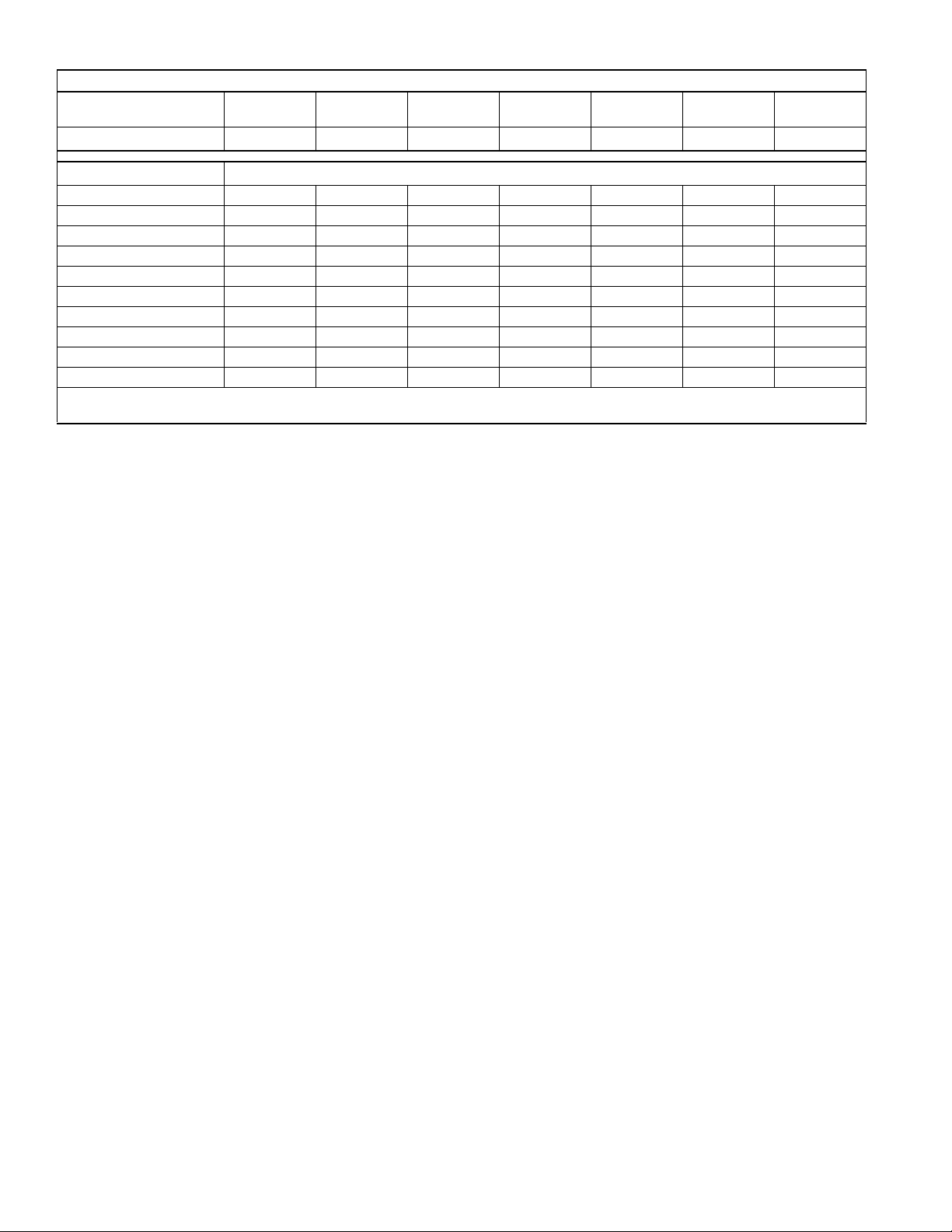
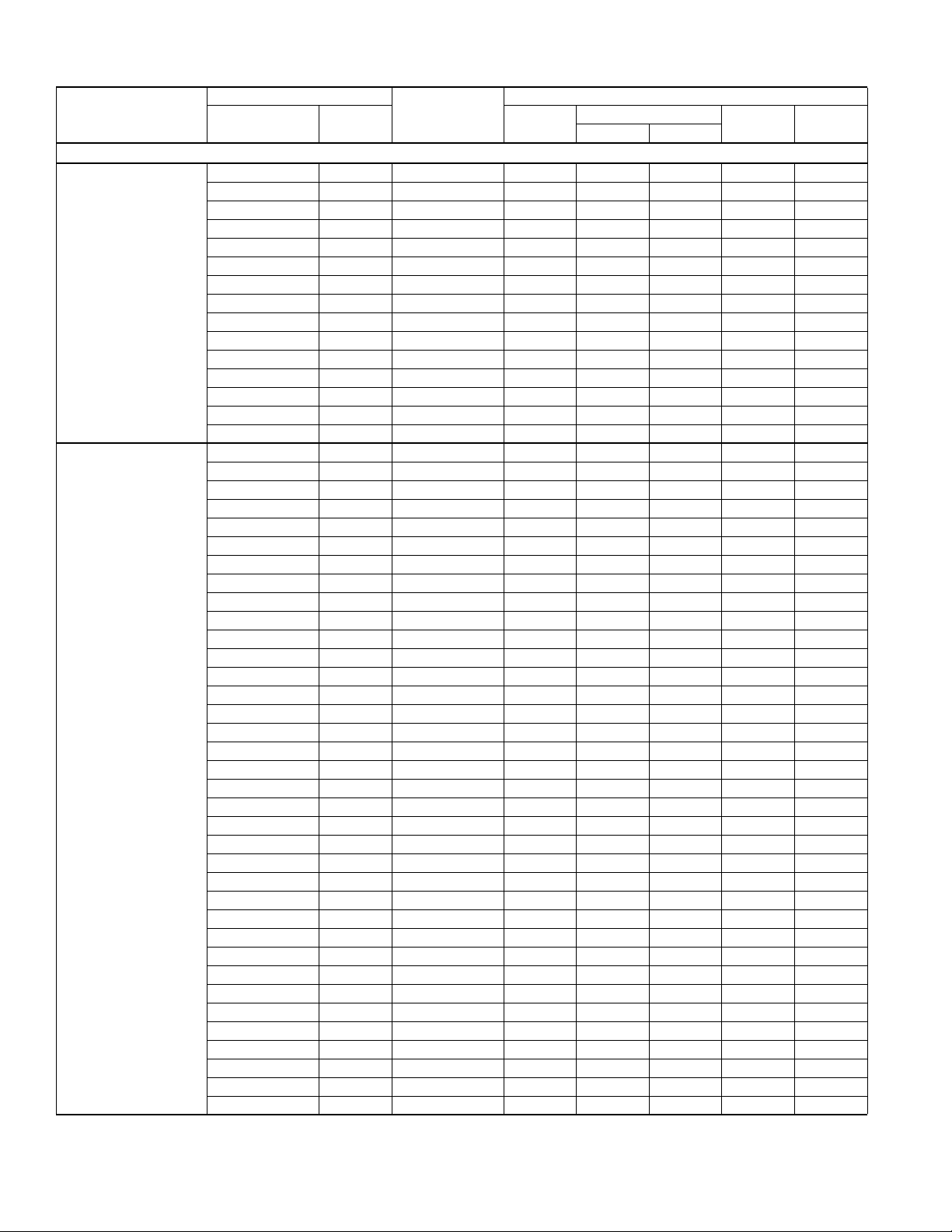
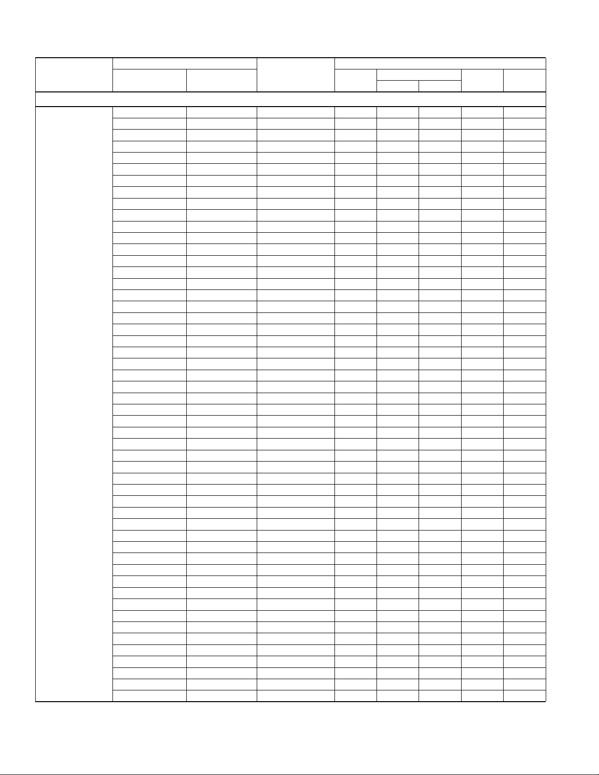
System Charge for Various Matched Systems
TCGF18
S41S3(E)
4F1 4F1 4G1 4G1 4G1 4J1 4J1
TCGF24
S41S3(E)
TCGF30
S41S3(E)
TCGF36
S41S3(E)
TCGF42
S41S3(E)
TCGF48
S41S3(E)
TCGF60
S41S3(E)
Indoor Unit
3,4,5
Additional Charge, oz
AHE18B 0 – – – – – –
AHE24B 15 16 – – – – –
AHE30B 15 16 13 – – – –
AHE36C 24 23 19 15 – – –
AHE42D – 35 30 25 17 – –
AHE48D – – – 24 16 16 –
AHE60D – – – 29 22 21 18
AHP18 0 – – – – – –
AHP36 – – 19 15 – – –
AHP60 – – – – – 16 –
AHR18B 0 – – – – – –
AHR24B – 16 – – – – –
AHR30B – – 12 – – – –
AHR36B – – 19 15 – – –
AHR42C – – – 25 17 – –
AHR48D – – – – 16 16 –
AHR60D – – – – 22 22 18
AHX18 0 – – – – – –
AHX24 11 13 – – – – –
AHX30 15 16 12 – – – –
AHX36 23 23 19 15 – – –
AHX42 – – 30 25 17 – –
AHX48 – – 29 23 16 16 –
AHX60 – – – 30 22 22 18
AV*24 3 – – – – – –
AV*36 23 23 19 15 – – –
AV*48 – – – 24 18 16 –
AV*60 – – – – 18 16 13
F4FP024 0 – – – – – –
F4FV060 – – – 24 18 16 –
F5FP048 – – – 18 17 11 –
F5FP060 – – – 14 16 16 –
F6FP018 0 – – – – – –
F6FP024 3 – – – – – –
F6FP030 15 16 13 – – – –
F6FP036 – – 13 9 – – –
F6FP042 – – 23 18 17 – –
F6FP048 – – 29 24 16 16 –
F6FP060 – – – 30 22 22 18
FC/MC/PC18 0 – – – – – –
FC/MC/PC32 15 16 13 – – – –
FC/MC/PC35 15 16 13 – – – –
FC/MC/PC37 23 22 19 15 – – –
FC/MC/PC43 23 22 19 15 8 – –
FC/MC/PC48 – 34 30 25 17 17 –
For notes see Page 4.
Johnson Controls Unitary Products 3
Page 4
700700-CTG-A-0312
Outdoor Unit
Required TXV
1,2
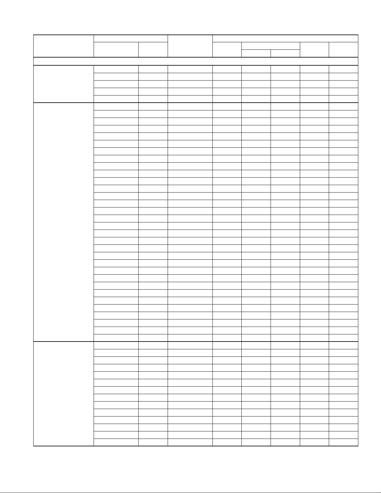
System Charge for Various Matched Systems
TCGF18
S41S3(E)
4F1 4F1 4G1 4G1 4G1 4J1 4J1
TCGF24
S41S3(E)
TCGF30
S41S3(E)
TCGF36
S41S3(E)
TCGF42
S41S3(E)
TCGF48
S41S3(E)
TCGF60
S41S3(E)
Indoor Unit
3,4,5
Additional Charge, oz
FC/MC/PC60 – – – 24 16 16 13
FC/MC62 – – – 29 21 21 18
FC64 – – – 39 30 29 26
HD24 14 – – – – – –
HD36 19 19 16 – – – –
HD48 – 45 40 34 26 25 –
HD60 – – – – 22 22 18
UC18 2 – – – – – –
UC48 – – – – 11 – –
UC60 – – – 24 16 – –
Some of the combinations shown in the above System Charge table require Advanced Main Air Circulating Fan indoor product. For approved coil
only matches, please see the “COOLING CAPACITY - Upflow, Downflow & Horizontal Furnaces and Coils” table.
FOOTNOTES:
1. For applications requiring a TXV use S1-1TVM*** series kit.
2. A TXV kit must be used with these indoor units to obtain system performance.
3. Systems matched with furnaces or air handlers not equipped with blower-off delays may require blower Time Delay Kit S1-2FD06700224.
4. PC coils cannot be used in downflow or horizontal applications. FC coils cannot be used in horizontal applications.
5. Refer to Technical Guide for actual system performan ce for specif ied system matches.
PROCEDURES:
1. Unit factory charge listed on the unit nameplate includes refrigerant for the outdoor unit, the smallest matched indoor unit, and 15 feet of interconnecting line tubing.
2. Verify the TXV or orifice and additional charge required for specific matched indoor unit in the system using the above table.
3. Add additional charge for the amount of interconnecting line tubing greater than 15 feet at the rate specified in Physical and Electrical Data Table.
4. For indoor matches requiring additional charge, the refrigerant needs to be weighed in for specific matched indoor unit and lineset length.
5. Permanently mark the unit nameplate with the total system charge. Total System Charge = Base Charge (as shipped) + charge adder for matched indoor unit +
charge adder for line set.
4 Johnson Controls Unitary Products
Page 5
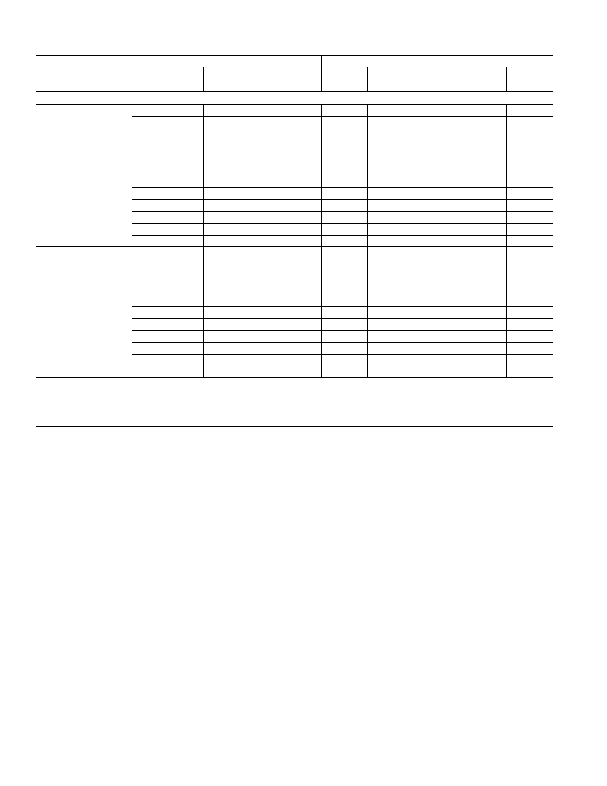
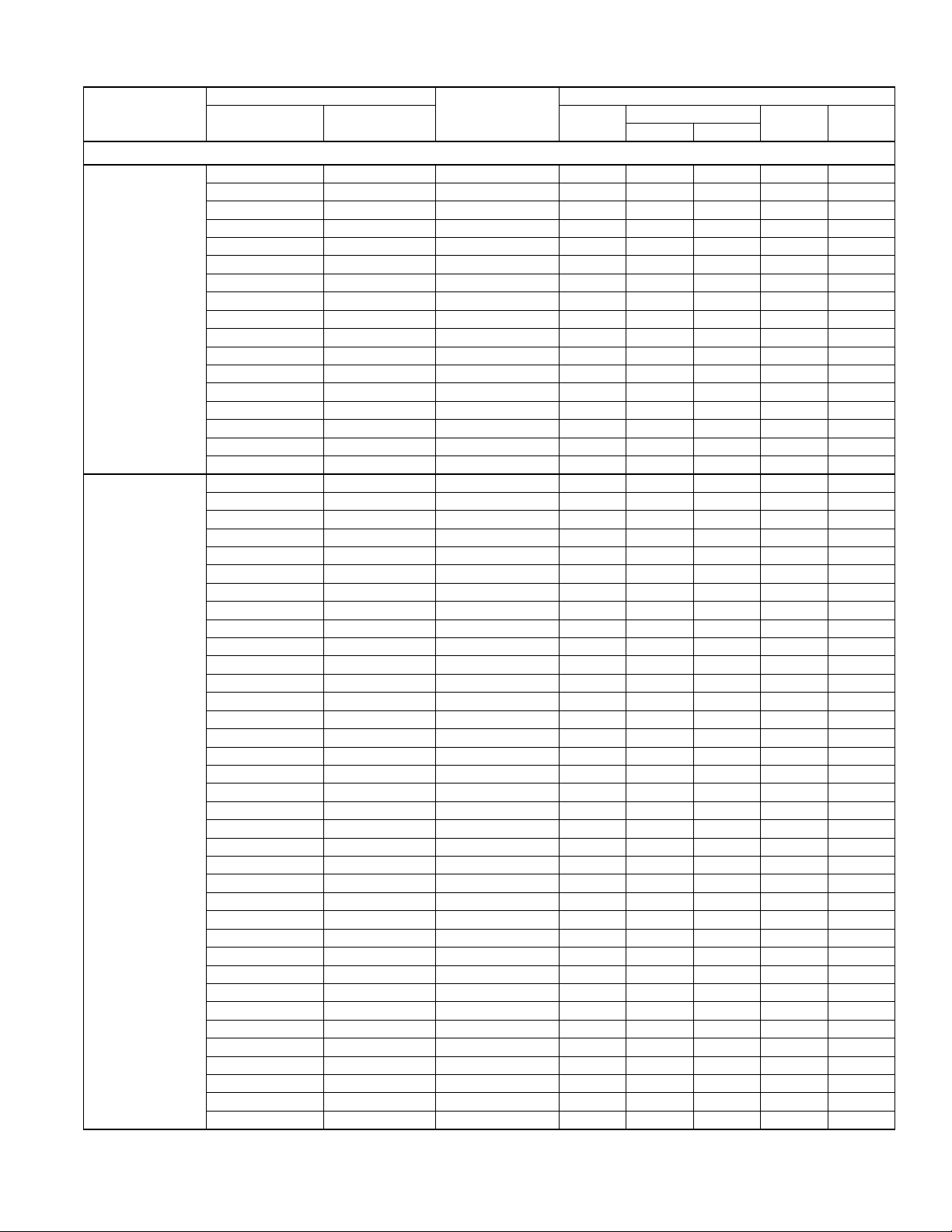
COOLING CAPACITY - With Air Handler Coils
UNIT
MODEL
TCGF18S41S3(E)
TCGF24S41S3(E)
TCGF30S41S3(E)
For notes see Page 8.
AIR HANDLER
MODEL WIDTH
14.5 SEER AC WITH AIR HANDLERS
AHE18B 17.5 – 610 17.9 13.0 16.25 13.25
AHE24B 17.5 – 585 18.1 13.1 16.75 13.50
AHE30B 17.5 – 585 18.1 13.1 16.75 13.50
AHE36C 21.0 – 730 19.2 15.0 17.50 14.25
AHP18 17.5 – 600 17.3 12.4 14.00 11.50
AHR18B 17.5 – 665 17.7 13.1 14.25 12.00
AHX18 17.5 – 630 18.0 13.2 16.50 13.50
AHX24 17.5 – 590 18.0 13.0 16.75 13.50
AHX30 17.5 – 610 18.3 13.4 17.00 13.75
AHX36 21.0 – 600 18.5 13.4 17.25 14.00
AV*24 17.5 – 610 18.1 13.2 16.50 13.50
AV*36 21.0 – 630 18.7 13.8 17.50 14.00
F4FP024 17.5 – 600 17.2 12.2 13.75 11.50
F6FP018 17.5 – 600 17.6 12.5 15.75 12.75
F6FP024 17.5 – 600 18.1 13.1 16.25 13.25
F6FP030 21.0 – 620 18.2 13.3 16.50 13.25
MV12B 17.5 FC/MC18B 600 17.9 12.7 16.25 13.25
MV12B 17.5 FC/MC35B 600 18.2 13.1 16.50 13.25
MV12B 17.5 FC/MC43B 600 18.4 13.2 16.75 13.50
MX12B 17.5 FC/MC18B 585 17.9 12.8 16.50 13.50
MX12B 17.5 FC/MC35B 660 18.6 14.1 17.50 14.25
MX12B 17.5 FC/MC43B 620 18.5 13.3 17.50 14.00
AHE24B 17.5 – 795 25.2 18.7 16.25 13.50
AHE30B 17.5 – 795 25.2 18.7 16.25 13.50
AHE36C 21.0 – 855 26.2 19.7 17.00 14.25
AHE42D 24.5 – 820 26.4 19.5 17.25 14.50
AHR24B 17.5 – 740 24.8 17.7 15.00 12.75
AHX24 17.5 – 800 25.2 18.4 15.75 13.25
AHX30 17.5 – 820 25.8 19.3 16.00 13.25
AHX36 21.0 – 820 25.6 18.8 15.75 13.25
AV*36 21.0 – 725 25.8 18.6 16.50 13.75
F6FP030 21.0 – 850 25.6 19.1 15.60 13.10
MV12B 17.5 FC/MC35B 800 25.6 18.0 16.00 13.50
MV12B 17.5 FC/MC43B 800 25.8 18.4 16.10 13.75
MV12D 24.5 FC/MC48D 845 26.4 19.8 17.25 14.50
MV16C 21.0 FC/MC35C 800 25.6 18.0 16.00 13.50
MV16C 21.0 FC/MC43C 800 25.8 18.4 16.10 13.75
MV16C 21.0 FC/MC48C 800 26.2 18.7 16.50 14.00
MX12B 17.5 FC/MC35B 815 25.6 18.8 17.00 14.25
MX12B 17.5 FC/MC43B 735 25.6 18.4 16.75 14.00
AHE30B 17.5 – 985 29.6 21.1 15.50 13.00
AHE36C 21.0 – 1000 30.4 21.9 16.25 13.75
AHE42D 24.5 – 1000 30.8 22.3 16.75 14.00
AHP36 21.0 – 1000 29.6 21.4 14.30 12.20
AHR30B 17.5 – 1115 29.8 21.9 14.25 12.00
AHR36B 17.5 – 1060 30.0 21.7 14.50 12.25
AHX30 17.5 – 1025 29.6 22.0 15.25 13.00
AHX36 21.0 – 1005 30.2 22.6 16.25 13.00
AHX42 24.5 – 990 30.6 22.8 16.50 13.25
AHX48 24.5 – 1090 31.0 23.6 16.50 13.25
AV*36 21.0 – 960 30.4 22.7 16.25 13.50
COIL
MODEL
700700-CTG-A-0312
COOLING
1
RATED
CFM
NET MBH
TOTAL SENS.
SEER EER
Johnson Controls Unitary Products 5
Page 6
700700-CTG-A-0312
COOLING CAPACITY - With Air Handler Coils (Continued)
UNIT
MODEL
TCGF30S41S3(E)
TCGF36S41S3(E)
For notes see Page 8.
AIR HANDLER
MODEL WIDTH
14.5 SEER AC WITH AIR HANDLERS
F6FP030 21.0 – 1035 29.2 21.8 14.75 12.50
F6FP036 21.0 – 980 29.2 21.6 15.25 13.00
F6FP042 24.5 – 1065 30.8 23.4 16.50 13.25
F6FP048 24.5 – 1055 28.2 21.6 14.75 12.50
MV12B 17.5 FC/MC35B 1000 29.6 21.4 15.25 13.00
MV12B 17.5 FC/MC43B 1000 30.2 22.0 15.75 13.25
MV16C 21.0 FC/MC35C 1000 29.6 21.4 15.50 13.25
MV16C 21.0 FC/MC43C 1000 30.2 22.0 16.00 13.50
MV16C 21.0 FC/MC48C 1000 30.6 22.2 16.00 13.50
MV20D 24.5 FC/MC48D 1000 30.6 22.2 16.00 13.50
MX12B 17.5 FC/MC35B 1085 30.4 22.1 16.00 13.25
MX12B 17.5 FC/MC43B 1095 30.8 22.7 16.25 13.50
MX16C 21.0 FC/MC35C 1035 30.2 21.7 16.50 13.75
MX16C 21.0 FC/MC43C 970 30.4 22.1 16.75 14.00
MX16C 21.0 FC/MC48C 995 30.8 22.3 17.00 14.25
AHE36C 21.0 – 1190 35.0 26.0 16.00 13.50
AHE42D 24.5 – 1180 35.2 26.4 16.50 13.75
AHE48D 24.5 – 1195 35.0 26.2 16.50 13.75
AHE60D 24.5 – 1190 35.4 26.6 16.75 14.00
AHP36 21.0 – 1200 34.6 25.6 15.00 12.50
AHR36B 17.5 – 1245 34.2 25.2 14.25 12.00
AHR42C 21.0 – 1230 34.8 26.2 14.75 12.50
AHX36 21.0 – 1225 35.2 26.0 16.00 13.00
AHX42 24.5 – 1190 35.6 26.2 16.25 13.00
AHX48 24.5 – 1255 35.8 26.8 16.25 13.00
AHX60 24.5 – 1300 36.0 27.2 16.25 13.00
AV*36 21.0 – 1190 35.2 25.7 15.75 13.20
AV*48 24.5 – 1220 33.6 24.8 15.25 13.00
F4FV060 24.5 – 1200 33.8 25.0 15.50 13.00
F5FP048 24.5 – 1235 35.6 26.7 16.25 13.50
F5FP060 24.5 – 1235 34.0 25.4 15.25 12.75
F6FP036 21.0 – 1210 34.0 24.8 15.00 12.50
F6FP042 24.5 – 1290 35.6 27.0 15.75 13.00
F6FP048 24.5 – 1125 33.4 24.0 15.25 12.75
F6FP060 24.5 – 1240 35.8 26.6 16.00 13.00
MV12B 17.5 FC/MC43B 1200 34.8 25.6 15.50 13.00
MV12D 24.5 FC/MC48D 1160 35.2 25.8 16.00 13.25
MV12D 24.5 FC/MC60D 1135 34.6 25.4 16.00 13.25
MV12D 24.5 FC/MC62D 1155 35.4 26.6 16.75 14.00
MV12D 24.5 FC64D 1155 36.0 27.0 17.00 13.50
MV16C 21.0 FC/MC43C 1200 35.0 25.8 16.00 13.25
MV16C 21.0 FC/MC48C 1200 35.4 26.4 16.25 13.25
MV20D 24.5 FC/MC48D 1300 35.8 27.6 16.50 14.00
MV20D 24.5 FC/MC60D 1300 35.2 27.2 16.25 13.50
MV20D 24.5 FC/MC62D 1300 35.6 27.6 16.50 13.75
MV20D 24.5 FC64D 1300 36.0 27.0 16.50 13.50
MX12B 17.5 FC/MC43B 1220 35.0 26.2 15.50 13.00
MX12D 24.5 FC/MC48D 1225 35.4 26.8 16.25 13.50
MX12D 24.5 FC/MC60D 1275 35.2 26.8 16.25 13.50
MX12D 24.5 FC/MC62D 1270 35.8 27.4 16.75 14.00
MX12D 24.5 FC64D 1270 36.8 28.6 17.25 14.50
COIL
MODEL
1
RATED
CFM
COOLING
NET MBH
TOTAL SENS.
SEER EER
6 Johnson Controls Unitary Products
Page 7
COOLING CAPACITY - With Air Handler Coils (Continued)
UNIT
MODEL
TCGF36S41S3(E)
TCGF42S41S3(E)
TCGF48S41S3(E)
For notes see Page 8.
AIR HANDLER
MODEL WIDTH
14.5 SEER AC WITH AIR HANDLERS
MX16C 21.0 FC/MC43C 1140 34.8 25.8 16.50 13.75
MX16C 21.0 FC/MC48C 1150 35.2 26.4 16.75 14.00
MX20D 24.5 FC/MC60D 1295 35.4 27.4 16.75 14.00
MX20D 24.5 FC/MC62D 1260 35.6 27.4 16.75 14.00
MX20D 24.5 FC64D 1260 36.8 28.6 17.25 14.50
AHE42D 24.5 – 1385 41.5 31.0 16.00 13.25
AHE48D 24.5 – 1385 40.5 30.6 16.00 13.00
AHE60D 24.5 – 1390 41.5 31.4 16.25 13.25
AHR42C 21.0 – 1485 41.0 31.2 14.75 12.00
AHR48D 24.5 – 1320 39.5 29.2 14.25 11.75
AHR60D 24.5 – 1350 40.5 30.2 14.75 12.25
AHX42 24.5 – 1395 42.0 31.6 16.00 13.00
AHX48 24.5 – 1445 42.0 32.2 16.00 13.00
AHX60 24.5 – 1440 42.0 32.2 15.75 13.00
AV*48 24.5 – 1385 40.0 29.8 14.75 12.50
AV*60 24.5 – 1360 40.0 29.8 14.75 12.50
F4FV060 24.5 – 1350 40.0 29.6 14.75 12.50
F5FP048 24.5 – 1455 42.0 32.0 15.50 13.00
F5FP060 24.5 – 1485 40.0 29.8 14.75 12.50
F6FP042 24.5 – 1455 42.0 32.0 15.00 12.50
F6FP048 24.5 – 1380 39.5 29.6 15.00 12.75
F6FP060 24.5 – 1475 42.0 32.0 15.50 13.00
MV12D 24.5 FC64D 1155 42.0 30.4 16.00 13.00
MV16C 21.0 FC/MC43C 1400 41.0 30.8 15.00 12.75
MV16C 21.0 FC/MC48C 1400 41.5 31.2 15.50 13.00
MV16C 21.0 FC60C 1400 40.5 30.6 15.50 12.75
MV20D 24.5 FC/MC48D 1400 42.0 31.4 15.50 13.00
MV20D 24.5 FC/MC60D 1400 41.5 31.4 15.50 13.00
MV20D 24.5 FC/MC62D 1400 42.0 31.4 16.00 13.00
MV20D 24.5 FC64D 1300 42.0 31.4 16.50 13.50
MX16C 21.0 FC/MC43C 1365 41.0 30.6 16.00 13.25
MX16C 21.0 FC/MC48C 1390 41.5 31.2 16.25 13.25
MX16C 21.0 FC60C 1420 40.5 30.8 16.00 13.00
MX20D 24.5 FC/MC48D 1415 41.5 31.2 16.00 13.25
MX20D 24.5 FC/MC60D 1470 41.0 31.6 16.25 13.25
MX20D 24.5 FC/MC62D 1470 41.5 32.2 16.25 13.50
MX20D 24.5 FC64D 1470 43.0 33.4 16.75 13.75
AHE48D 24.5 – 1600 47.0 33.6 15.50 13.25
AHE60D 24.5 – 1565 48.0 34.2 16.00 13.50
AHP60 24.5 – 1600 44.0 30.6 14.20 12.00
AHR48D 24.5 – 1610 47.0 33.6 14.50 12.50
AHR60D 24.5 – 1620 47.5 34.2 14.75 12.75
AHX48 24.5 – 1660 47.5 34.4 14.75 12.50
AHX60 24.5 – 1680 48.0 34.4 15.00 12.50
AV*48 24.5 – 1625 47.0 33.4 14.25 12.00
AV*60 24.5 – 1560 44.0 31.4 14.25 12.00
F4FV060 24.5 – 1600 44.5 30.6 14.25 12.00
F5FP048 24.5 – 1690 47.5 34.0 15.00 12.75
F5FP060 24.5 – 1680 44.5 31.2 14.00 12.00
F6FP048 24.5 – 1625 44.5 31.2 14.25 12.25
F6FP060 24.5 – 1710 48.0 34.8 15.00 12.50
COIL
MODEL
1
RATED
CFM
COOLING
NET MBH
TOTAL SENS.
700700-CTG-A-0312
SEER EER
Johnson Controls Unitary Products 7
Page 8
700700-CTG-A-0312
COOLING CAPACITY - With Air Handler Coils (Continued)
UNIT
MODEL
AIR HANDLER
MODEL WIDTH
COIL
MODEL
1
RATED
CFM
TOTAL SENS.
14.5 SEER AC WITH AIR HANDLERS
MV16C 21.0 FC/MC48C 1600 47.0 33.0 15.25 12.75
MV16C 21.0 FC60C 1625 47.0 33.8 15.25 13.00
MV20D 24.5 FC/MC48D 1600 47.0 33.0 15.25 12.75
MV20D 24.5 FC/MC60D 1600 47.0 33.0 15.25 12.75
MV20D 24.5 FC/MC62D 1630 47.5 33.2 15.50 12.75
TCGF48S41S3(E)
MV20D 24.5 FC64D 1400 48.0 33.6 16.00 13.00
MX16C 21.0 FC/MC48C 1685 47.5 34.2 15.50 13.00
MX16C 21.0 FC60C 1630 47.5 34.0 16.00 13.50
MX20D 24.5 FC/MC48D 1525 47.5 33.6 15.75 13.50
MX20D 24.5 FC/MC60D 1585 47.5 34.0 16.00 13.50
MX20D 24.5 FC/MC62D 1605 48.5 34.8 16.50 13.75
MX20D 24.5 FC64D 1605 50.0 36.6 16.75 14.00
AHE60D 24.5 – 1835 56.0 39.3 14.75 12.50
AHR60D 24.5 – 1870 55.5 39.3 13.75 11.75
AHX60 24.5 – 1570 55.0 36.8 14.50 12.50
AV*60 24.5 – 1730 55.0 37.0 13.75 12.00
F6FP060 24.5 – 1865 55.5 38.3 14.00 12.00
TCGF60S41S3(E)
MV20D 24.5 FC/MC60D 1800 55.0 39.0 13.50 11.95
MV20D 24.5 FC/MC62D 1855 56.5 39.5 14.25 12.50
MV20D 24.5 FC64D 1630 57.0 39.0 15.10 12.90
MX20D 24.5 FC/MC60D 1780 55.5 38.8 14.75 12.50
MX20D 24.5 FC/MC62D 1795 56.5 39.8 15.00 12.75
MX20D 24.5 FC64D 1795 58.5 41.3 15.50 13.25
Rated in accordance with DOE test procedures (Federal Register 12-27-79 and 3-18-88) and ANSI /AHRI Standard 210/240.
Cooling MBH based on 80°F entering air temperature, 50% RH (Relative Humidity), and rated air flow.
EER (Energy Efficiency Ratio) is the total cooling output in BTUs at 95°F outdoor ambient divided by the total electric power in watt-hours at those conditions.
SEER (Seasonal Energy Efficiency Ratio) is the total cooling output in BTUs during a normal annual usage period for cooling divided by the total electric power input in
watt-hours during the same period.
1. MC coils available with a factory installed horizontal dr ain pan. See price pages for specific model number.
— = Not applicable.
MA Modular Air Handlers use Coil Only Ratings.
COOLING
NET MBH
SEER EER
8 Johnson Controls Unitary Products
Page 9
COOLING CAPACITY - Upflow, Downflow & Horizontal Furnaces and Coils (Coil Only Ratings)
COOLING
NET MBH
UNIT MODEL
COIL
MODEL WIDTH
CFM RANGE
(MIN.-MAX.)
RATED
CFM
14.5 SEER AC COIL ONLY RATINGS
FC/MC/PC18 14.5,17.5 450-750 600 17.3 12.4 14.00 11.50
FC/MC/PC32 14.5 450-750 600 17.8 12.8 14.50 12.00
FC/MC/PC35 17.5,21.0 450-750 600 17.8 12.8 14.50 12.00
TCGF18S41S3(E)
FC/MC/PC37 14.5 450-750 600 18.0 12.9 14.75 12.00
FC/MC/PC43 17.5,21.0 450-750 600 18.0 12.9 14.75 12.00
HD24 – 450-750 600 17.9 12.8 14.50 12.00
HD36 – 450-750 600 17.3 11.9 14.00 11.50
UC18 14.5,17.5 450-750 600 17.4 12.5 14.00 11.75
FC/MC/PC32 14.5 500-900 700 24.4 17.2 14.50 12.30
FC/MC/PC35 17.5,21.0 500-900 800 25.0 17.6 14.50 12.35
FC/MC/PC37 14.5 500-900 800 25.4 17.9 14.50 12.35
TCGF24S41S3(E)
FC/MC/PC43 17.5,21.0 500-900 800 25.2 18.0 14.70 12.50
FC/MC/PC48 21.0,24.5 500-900 800 25.6 18.3 14.80 12.65
HD36 – 500-900 800 24.8 17.0 14.00 12.00
HD48 – 500-900 800 25.6 17.9 14.50 12.35
FC/MC/PC32 14.5 800-1200 1000 29.0 21.0 14.00 12.00
FC/MC/PC35 17.5,21.0 800-1200 1000 29.0 21.0 14.00 12.00
FC/MC/PC37 14.5 800-1200 1000 29.6 21.6 14.50 12.35
TCGF30S41S3(E)
FC/MC/PC43 17.5,21.0 800-1200 1000 29.6 21.8 14.50 12.30
FC/MC/PC48 21.0,24.5 800-1200 1000 30.0 21.8 14.50 12.35
HD36 – 800-1200 1000 28.8 20.2 14.00 12.00
HD48 – 800-1200 1000 29.8 21.4 14.50 12.35
FC/MC/PC37 14.5 1000-1400 1200 34.4 25.2 14.50 12.20
FC/MC/PC43 17.5,21.0 1000-1400 1200 34.2 25.0 14.50 12.30
FC/MC/PC48 21.0,24.5 1000-1400 1200 34.6 25.4 14.50 12.25
TCGF36S41S3(E)
FC/MC/PC60 21.0,24.5 1000-1400 1200 34.0 25.4 14.25 12.00
FC/MC62 24.5 1000-1400 1200 34.4 25.8 14.50 12.25
FC64 24.5 1000-1400 1200 35.6 26.8 14.75 12.50
HD48 – 1000-1400 1200 34.6 25.0 14.50 12.20
UC60 21.0,24.5 1000-1400 1200 33.2 23.8 14.00 11.75
FC/MC/PC43 17.5,21.0 1200-1600 1400 40.5 30.4 14.00 12.00
FC/MC/PC48 21.0,24.5 1200-1600 1400 40.5 30.4 14.50 12.00
FC/MC/PC60 21.0,24.5 1200-1600 1400 41.0 30.8 14.50 12.30
TCGF42S41S3(E)
FC/MC62 24.5 1200-1600 1400 41.0 31.0 14.50 12.30
FC64 24.5 1200-1600 1400 41.5 32.0 14.75 12.25
HD48 – 1200-1600 1400 41.0 30.4 14.25 12.10
HD60 – 1200-1600 1400 41.5 31.2 14.50 12.30
FC/MC/PC48 21.0,24.5 1400-1800 1600 46.5 32.8 14.25 12.10
FC/MC/PC60 21.0,24.5 1400-1800 1600 46.5 33.2 14.50 12.35
TCGF48S41S3(E)
FC/MC62 24.5 1400-1800 1600 47.0 32.8 14.50 12.35
FC64 24.5 1400-1800 1400 47.0 33.4 15.05 12.70
HD48 – 1400-1800 1600 46.5 32.6 14.50 12.35
HD60 – 1400-1800 1600 47.5 33.2 14.50 12.35
FC/MC/PC60 21.0,24.5 1600-2000 1800 54.5 38.5 13.80 11.90
TCGF60S41S3(E)
FC/MC62 24.5 1600-2000 1800 55.5 38.5 14.00 12.00
FC64 24.5 1600-2000 1800 56.0 38.6 14.35 12.30
1. Requires a S1-2FD06700224 Blower Time Delay unless a standard furnace is equipped with one.
MA Modular Air Handlers use Coil Only Ratings.
PSC furnaces, such as the TG8S, TGLS, and TG9S, use Coil Only Ratings.
TOTAL SENS.
700700-CTG-A-0312
1
SEER
EER
Johnson Controls Unitary Products 9
Page 10
700700-CTG-A-0312
COOLING CAP ACITY - With High Efficiency Motor Furnaces
UNIT
MODEL
TCGF18S41S3(E)
For notes see Page 19.
MODEL WIDTH
T*(8,L)V*A12 14.5 FC/MC/PC18A 615 17.8 12.7 16.00 13.00
T*(8,L)V*A12 14.5 FC/MC/PC32A 620 18.2 13.1 16.50 13.25
T*(8,L)V*A12 14.5 FC/MC/PC37A 635 18.6 13.8 17.00 13.75
T*(8,L)V*A12 14.5 HD24 640 18.6 13.7 17.00 13.75
T*(8,L)V*A12 14.5 HD36 645 18.0 12.8 16.25 13.25
T*(8,L)V*A12 14.5 UC18A 620 17.9 12.8 16.25 13.25
T*(8,L)V*B12 17.5 FC/MC/PC18B 625 17.8 12.7 16.00 13.00
T*(8,L)V*B12 17.5 FC/MC/PC35B 630 18.4 13.6 16.75 13.50
T*(8,L)V*B12 17.5 FC/MC/PC43B 570 18.2 13.0 16.75 13.50
T*(8,L)V*B12 17.5 HD24 575 18.5 13.2 17.25 14.00
T*(8,L)V*B12 17.5 HD36 650 18.1 12.9 16.50 13.25
T*(8,L)V*B12 17.5 UC18B 580 17.9 12.9 16.25 13.25
T*(8,L)V*C16 21.0 FC/MC/PC35C 645 18.4 13.8 17.00 13.50
T*(8,L)V*C16 21.0 HD24 600 18.4 13.1 17.25 13.75
T*(8,L)V*C16 21.0 HD36 595 17.8 12.3 16.50 13.25
T*(8,L)X*A12 14.5 FC/MC/PC18A 540 17.5 12.3 16.00 13.25
T*(8,L)X*A12 14.5 FC/MC/PC32A 590 18.4 13.2 17.25 14.00
T*(8,L)X*A12 14.5 FC/MC/PC37A 640 18.8 14.0 17.50 14.25
T*(8,L)X*A12 14.5 HD24 605 18.5 13.2 17.50 14.00
T*(8,L)X*A12 14.5 HD36 605 17.9 12.3 16.75 13.50
T*(8,L)X*A12 14.5 UC18A 590 18.0 12.9 16.75 13.50
T*(8,L)X*B12 17.5 FC/MC/PC18B 580 17.9 12.8 16.50 13.50
T*(8,L)X*B12 17.5 FC/MC/PC35B 640 18.4 13.8 17.50 14.00
T*(8,L)X*B12 17.5 FC/MC/PC43B 665 19.0 14.3 17.50 14.50
T*(8,L)X*B12 17.5 HD24 655 18.8 14.0 17.50 14.25
T*(8,L)X*B12 17.5 HD36 650 18.2 13.0 17.00 13.75
T*(8,L)X*B12 17.5 UC18B 595 18.0 12.9 16.75 13.50
T*(8,L)X*C16 21.0 FC/MC/PC35C 625 18.3 13.2 16.75 13.75
T*(8,L)X*C16 21.0 HD24 650 18.7 13.8 17.25 14.00
T*9V*A10 14.5 FC/MC/PC18A 580 17.7 12.5 15.25 12.75
T*9V*A10 14.5 FC/MC/PC32A 580 18.0 13.0 16.25 13.00
T*9V*A10 14.5 FC/MC/PC37A 570 18.2 13.0 16.25 13.25
T*9(C,V)*B12 17.5 FC/MC/PC18B 610 17.9 12.7 16.25 13.25
T*9(C,V)*B12 17.5 FC/MC/PC35B 570 18.0 12.9 16.50 13.50
T*9(C,V)*B12 17.5 HD24 610 18.4 13.1 17.00 13.75
T*9(C,V)*B12 17.5 HD36 635 18.0 12.8 16.50 13.25
T*9(C,V)*B12 17.5 UC18B 610 17.9 12.9 16.50 13.50
T*9(C,V)*C16 21.0 FC/MC/PC35C 645 18.4 13.8 17.00 13.75
T*9(C,V)*C16 21.0 HD36 595 17.8 12.3 16.50 13.25
T*9X*A10 14.5 FC/MC/PC18A 575 17.7 12.5 15.50 13.00
T*9X*A10 14.5 FC/MC/PC32A 585 18.1 13.0 16.25 13.25
T*9X*A10 14.5 FC/MC/PC37A 580 18.2 13.1 16.50 13.25
T*9X*B12 17.5 FC/MC/PC18B 590 17.9 12.8 16.50 13.50
T*9X*B12 17.5 FC/MC/PC35B 645 18.5 13.9 17.50 14.00
T*9X*B12 17.5 HD24 630 18.7 13.7 17.50 14.25
T*9X*B12 17.5 HD36 630 18.1 12.8 16.75 13.75
T*9X*B12 17.5 UC18B 590 18.0 12.9 16.75 13.50
C*(8,L)C*A12 14.5 FC/MC/PC18A 615 17.8 12.7 16.00 13.00
C*(8,L)C*A12 14.5 FC/MC/PC32A 620 18.2 13.1 16.50 13.25
C*(8,L)C*A12 14.5 FC/MC/PC37A 635 18.6 13.8 17.00 13.75
C*(8,L)C*A12 14.5 HD24 640 18.6 13.7 17.00 13.75
C*(8,L)C*A12 14.5 HD36 645 18.0 12.8 16.25 13.25
FURNACE
14.5 SEER AC WITH HIGH EFFICIENCY MOTOR FURNACES
COIL
MODEL
COOLING
1
RATED
CFM
NET MBH
TOTAL SENS.
2
SEER EER
10 Johnson Controls Unitary Products
Page 11
COOLING CAPACITY - With High Efficiency Motor Furnaces (Continued)
UNIT
MODEL
TCGF18S41S3(E)
TCGF24S41S3(E)
For notes see Page 19.
MODEL WIDTH
C*(8,L)C*A12 14.5 UC18A 620 17.9 12.8 16.25 13.25
C*(8,L)C*B12 17.5 FC/MC/PC18B 625 17.8 12.7 16.00 13.00
C*(8,L)C*B12 17.5 FC/MC/PC35B 630 18.4 13.6 16.75 13.50
C*(8,L)C*B12 17.5 FC/MC/PC43B 570 18.2 13.0 16.75 13.50
C*(8,L)C*B12 17.5 HD24 575 18.5 13.2 17.25 14.00
C*(8,L)C*B12 17.5 HD36 650 18.1 12.9 16.50 13.25
C*(8,L)C*B12 17.5 UC18B 580 17.9 12.9 16.25 13.25
C*(8,L)C*C16 21.0 FC/MC/PC35C 645 18.4 13.8 17.00 13.50
C*(8,L)C*C16 21.0 HD24 600 18.4 13.1 17.25 13.75
C*(8,L)C*C16 21.0 HD36 595 17.8 12.3 16.50 13.25
C*9C*B12 17.5 FC/MC/PC18B 610 17.9 12.7 16.25 13.25
C*9C*B12 17.5 FC/MC/PC35B 570 18.0 12.9 16.50 13.50
C*9C*B12 17.5 HD24 610 18.4 13.1 17.00 13.75
C*9C*B12 17.5 HD36 635 18.0 12.8 16.50 13.25
C*9C*B12 17.5 UC18B 610 17.9 12.9 16.50 13.50
C*9C*C16 21.0 FC/MC/PC35C 645 18.4 13.8 17.00 13.75
C*9C*C16 21.0 HD36 595 17.8 12.3 16.50 13.25
T*(8,L)V*A12 14.5 FC/MC/PC32A 775 24.0 16.8 15.50 13.25
T*(8,L)V*A12 14.5 FC/MC/PC37A 805 24.0 16.9 16.00 13.50
T*(8,L)V*A12 14.5 HD36 805 24.0 16.4 16.00 13.50
T*(8,L)V*B12 17.5 FC/MC/PC35B 760 24.0 16.8 15.75 13.25
T*(8,L)V*B12 17.5 FC/MC/PC43B 760 24.0 16.7 16.00 13.50
T*(8,L)V*B12 17.5 HD36 760 24.0 16.2 15.75 13.25
T*(8,L)V*C16 21.0 HD36 855 24.0 16.7 16.00 13.50
T*(8,L)V*C20 21.0 HD36 750 24.0 16.1 15.75 13.25
T*(8,L)X*A12 14.5 FC/MC/PC32A 800 25.8 19.1 15.75 13.25
T*(8,L)X*A12 14.5 FC/MC/PC37A 840 26.4 20.0 16.00 13.50
T*(8,L)X*A12 14.5 HD36 775 20.8 17.4 15.25 13.00
T*(8,L)X*B12 17.5 FC/MC/PC35B 850 26.0 19.3 15.75 13.25
T*(8,L)X*B12 17.5 FC/MC/PC43B 865 26.6 20.2 16.00 13.50
T*(8,L)X*B12 17.5 HD36 855 25.8 19.1 15.50 13.25
T*(8,L)X*C16 21.0 FC/MC/PC35C 625 24.6 17.2 15.75 13.25
T*(8,L)X*C16 21.0 FC/MC/PC43C 655 25.2 17.9 16.00 13.50
T*(8,L)X*C16 21.0 FC/MC/PC48C 685 25.6 18.4 15.75 13.25
T*(8,L)X*C20 21.0 FC/MC/PC35C 885 26.2 20.0 15.75 13.50
T*9V*A10 14.5 FC/MC/PC32A 785 25.0 18.2 15.25 12.75
T*9V*A10 14.5 FC/MC/PC37A 790 25.4 18.6 15.50 13.00
T*9(C,V)*B12 17.5 FC/MC/PC35B 815 24.0 17.0 15.75 13.25
T*9(C,V)*B12 17.5 FC/MC/PC43B 800 24.0 16.8 16.00 13.50
T*9(C,V)*B12 17.5 HD36 815 24.0 16.4 15.75 13.25
T*9(C,V)*C16 21.0 FC/MC/PC35C 875 25.2 17.6 16.00 13.00
T*9(C,V)*C16 21.0 HD36 785 24.0 16.4 16.00 13.50
T*9(C,V)*C20 21.0 HD36 760 24.0 16.1 15.75 13.25
T*9X*A10 14.5 FC/MC/PC32A 745 25.0 17.9 15.50 13.00
T*9X*A10 14.5 FC/MC/PC37A 740 25.2 18.2 15.75 13.25
T*9X*B12 17.5 FC/MC/PC35B 785 25.8 19.3 15.75 13.25
T*9X*B12 17.5 FC/MC/PC43B 800 26.2 19.5 16.00 13.50
T*9X*B12 17.5 HD36 790 25.4 18.3 15.25 13.00
T*9X*C16 21.0 FC/MC/PC35C 715 25.2 18.3 15.75 13.25
T*9X*C16 21.0 FC/MC/PC43C 735 25.8 18.8 16.00 13.50
T*9X*C16 21.0 FC/MC/PC48C 770 26.2 19.5 15.75 13.25
T*9X*C20 21.0 FC/MC/PC35C 825 25.8 19.2 15.75 13.50
T*9X*C20 21.0 FC/MC/PC43C 790 26.2 19.4 15.75 13.25
FURNACE
14.5 SEER AC WITH HIGH EFFICIENCY MOTOR FURNACES
COIL
MODEL
1
RATED
CFM
COOLING
NET MBH
TOTAL SENS.
2
700700-CTG-A-0312
SEER EER
Johnson Controls Unitary Products 11
Page 12

700700-CTG-A-0312
COOLING CAP ACITY - With High Efficiency Motor Furnaces (Continued)
UNIT
MODEL
TCGF24S41S3(E)
TCGF30S41S3(E)
For notes see Page 19.
MODEL WIDTH
T*9X*C20 21.0 FC/MC/PC48C 815 26.8 20.2 15.75 13.25
C*(8,L)C*A12 14.5 FC/MC/PC32A 775 24.0 16.8 15.50 13.25
C*(8,L)C*A12 14.5 FC/MC/PC37A 805 24.0 16.9 16.00 13.50
C*(8,L)C*A12 14.5 HD36 805 24.0 16.4 16.00 13.50
C*(8,L)C*B12 17.5 FC/MC/PC35B 760 24.0 16.8 15.75 13.25
C*(8,L)C*B12 17.5 FC/MC/PC43B 760 24.0 16.7 16.00 13.50
C*(8,L)C*B12 17.5 HD36 760 24.0 16.2 15.75 13.25
C*(8,L)C*C16 21.0 HD36 855 24.0 16.7 16.00 13.50
C*(8,L)C*C20 21.0 HD36 750 24.0 16.1 15.75 13.25
C*9C*B12 17.5 FC/MC/PC35B 815 24.0 17.0 15.75 13.25
C*9C*B12 17.5 FC/MC/PC43B 800 24.0 16.8 16.00 13.50
C*9C*B12 17.5 HD36 815 24.0 16.4 15.75 13.25
C*9C*C16 21.0 FC/MC/PC35C 875 25.2 17.6 16.00 13.00
C*9C*C16 21.0 HD36 785 24.0 16.4 16.00 13.50
C*9C*C20 21.0 HD36 760 24.0 16.1 15.75 13.25
T*(8,L)V*A12 14.5 FC/MC/PC32A 1045 29.2 21.6 14.50 12.25
T*(8,L)V*A12 14.5 FC/MC/PC37A 980 29.8 21.6 15.00 12.75
T*(8,L)V*A12 14.5 HD36 1000 29.0 20.6 15.00 12.75
T*(8,L)V*B12 17.5 FC/MC/PC35B 1020 29.2 22.0 15.20 12.85
T*(8,L)V*B12 17.5 FC/MC/PC43B 1045 30.0 22.6 15.70 13.30
T*(8,L)V*B12 17.5 HD36 985 29.2 20.6 15.50 13.00
T*(8,L)V*C16 21.0 FC/MC/PC35C 985 29.4 21.8 15.70 13.25
T*(8,L)V*C16 21.0 FC/MC/PC43C 990 30.0 22.0 16.25 13.50
T*(8,L)V*C16 21.0 FC/MC/PC48C 1010 30.0 22.2 16.50 13.75
T*(8,L)V*C16 21.0 HD36 1020 29.2 20.8 15.75 13.00
T*(8,L)V*C20 21.0 FC/MC/PC35C 1035 29.6 22.0 15.60 13.20
T*(8,L)V*C20 21.0 FC/MC/PC43C 1000 30.0 22.0 16.25 13.75
T*(8,L)V*C20 21.0 FC/MC/PC48C 1040 30.0 22.2 16.50 13.75
T*(8,L)V*C20 21.0 HD36 1055 29.6 21.4 15.75 13.25
T*(8,L)X*A12 14.5 FC/MC/PC32A 970 29.2 21.4 15.25 13.00
T*(8,L)X*A12 14.5 FC/MC/PC37A 1105 30.6 23.4 15.25 13.00
T*(8,L)X*A12 14.5 HD36 1115 29.8 22.8 15.00 12.75
T*(8,L)X*B12 17.5 FC/MC/PC35B 1120 30.0 22.8 15.75 13.25
T*(8,L)X*B12 17.5 FC/MC/PC43B 1125 30.8 23.6 16.00 13.50
T*(8,L)X*B12 17.5 HD36 1120 30.0 23.0 15.50 13.00
T*(8,L)X*C16 21.0 FC/MC/PC35C 1105 30.0 23.0 15.75 13.25
T*(8,L)X*C16 21.0 FC/MC/PC43C 855 28.4 19.7 16.00 13.50
T*(8,L)X*C16 21.0 FC/MC/PC48C 875 29.0 20.2 16.25 13.25
T*(8,L)X*C16 21.0 HD36 1120 30.0 22.6 15.50 13.00
T*(8,L)X*C20 21.0 FC/MC/PC35C 850 29.0 20.8 15.75 13.25
T*(8,L)X*C20 21.0 FC/MC/PC43C 870 29.8 21.4 16.00 13.50
T*(8,L)X*C20 21.0 FC/MC/PC48C 890 30.0 22.0 16.25 13.25
T*9(C,V)*B12 17.5 FC/MC/PC35B 1045 29.4 21.8 15.00 12.50
T*9(C,V)*B12 17.5 FC/MC/PC43B 1035 29.8 21.8 15.25 12.75
T*9(C,V)*B12 17.5 HD36 985 29.2 20.6 15.25 12.75
T*9(C,V)*C16 21.0 FC/MC/PC35C 1005 29.6 22.0 15.75 13.25
T*9(C,V)*C16 21.0 FC/MC/PC43C 1030 30.0 22.0 15.50 13.25
T*9(C,V)*C16 21.0 FC/MC/PC48C 990 30.0 22.2 16.25 13.50
T*9(C,V)*C16 21.0 HD36 1005 29.2 20.8 15.75 13.25
T*9(C,V)*C20 21.0 FC/MC/PC35C 985 29.6 22.0 15.75 13.25
T*9(C,V)*C20 21.0 FC/MC/PC43C 995 30.0 22.0 16.00 13.50
T*9(C,V)*C20 21.0 FC/MC/PC48C 965 30.0 22.2 16.25 13.50
T*9(C,V)*C20 21.0 HD36 1045 29.2 20.6 15.50 13.00
FURNACE
14.5 SEER AC WITH HIGH EFFICIENCY MOTOR FURNACES
COIL
MODEL
1
RATED
CFM
COOLING
NET MBH
TOTAL SENS.
2
SEER EER
12 Johnson Controls Unitary Products
Page 13

COOLING CAPACITY - With High Efficiency Motor Furnaces (Continued)
UNIT
MODEL
TCGF30S41S3(E)
TCGF36S41S3(E)
For notes see Page 19.
MODEL WIDTH
T*9(C,V)*D20 24.5 FC/MC/PC48D 1085 30.0 22.6 16.25 13.50
T*9X*A10 14.5 FC/MC/PC32A 1035 29.4 21.1 14.00 12.00
T*9X*A10 14.5 FC/MC/PC37A 1025 29.6 21.5 14.25 12.00
T*9X*B12 17.5 FC/MC/PC35B 1085 30.0 22.6 15.00 13.00
T*9X*B12 17.5 FC/MC/PC43B 1095 30.6 23.4 16.00 13.25
T*9X*C16 21.0 FC/MC/PC35C 1075 30.0 22.6 15.00 13.00
T*9X*C16 21.0 FC/MC/PC43C 1055 30.6 23.0 16.00 13.25
T*9X*C16 21.0 FC/MC/PC48C 1075 30.8 23.4 16.00 13.25
T*9X*C20 21.0 FC/MC/PC35C 825 27.4 19.0 14.50 12.30
T*9X*C20 21.0 FC/MC/PC43C 720 28.4 19.6 16.00 13.25
T*9X*C20 21.0 FC/MC/PC48C 745 29.0 20.2 16.00 13.25
T*9X*D20 24.5 FC/MC/PC48D 780 29.2 20.6 16.00 13.25
C*(8,L)C*A12 14.5 FC/MC/PC32A 1045 29.2 21.6 14.50 12.25
C*(8,L)C*A12 14.5 FC/MC/PC37A 980 29.8 21.6 15.00 12.75
C*(8,L)C*A12 14.5 HD36 1000 29.0 20.6 15.00 12.75
C*(8,L)C*B12 17.5 FC/MC/PC35B 1020 29.2 22.0 15.20 12.85
C*(8,L)C*B12 17.5 FC/MC/PC43B 1045 30.0 22.6 15.70 13.30
C*(8,L)C*B12 17.5 HD36 985 29.2 20.6 15.50 13.00
C*(8,L)C*C16 21.0 FC/MC/PC35C 985 29.4 21.8 15.70 13.25
C*(8,L)C*C16 21.0 FC/MC/PC43C 990 30.0 22.0 16.25 13.50
C*(8,L)C*C16 21.0 FC/MC/PC48C 1010 30.0 22.2 16.50 13.75
C*(8,L)C*C16 21.0 HD36 1020 29.2 20.8 15.75 13.00
C*(8,L)C*C20 21.0 FC/MC/PC35C 1035 29.6 22.0 15.60 13.20
C*(8,L)C*C20 21.0 FC/MC/PC43C 1000 30.0 22.0 16.25 13.75
C*(8,L)C*C20 21.0 FC/MC/PC48C 1040 30.0 22.2 16.50 13.75
C*(8,L)C*C20 21.0 HD36 1055 29.6 21.4 15.75 13.25
C*9C*B12 17.5 FC/MC/PC35B 1045 29.4 21.8 15.00 12.50
C*9C*B12 17.5 FC/MC/PC43B 1035 29.8 21.8 15.25 12.75
C*9C*B12 17.5 HD36 985 29.2 20.6 15.25 12.75
C*9C*C16 21.0 FC/MC/PC35C 1005 29.6 22.0 15.75 13.25
C*9C*C16 21.0 FC/MC/PC43C 1030 30.0 22.0 15.50 13.25
C*9C*C16 21.0 FC/MC/PC48C 990 30.0 22.2 16.25 13.50
C*9C*C16 21.0 HD36 1005 29.2 20.8 15.75 13.25
C*9C*C20 21.0 FC/MC/PC35C 985 29.6 22.0 15.75 13.25
C*9C*C20 21.0 FC/MC/PC43C 995 30.0 22.0 16.00 13.50
C*9C*C20 21.0 FC/MC/PC48C 965 30.0 22.2 16.25 13.50
C*9C*C20 21.0 HD36 1045 29.2 20.6 15.50 13.00
C*9C*D20 24.5 FC/MC/PC48D 1085 30.0 22.6 16.25 13.50
T*(8,L)V*A12 14.5 FC/MC/PC37A 1150 34.2 24.8 14.95 12.40
T*(8,L)V*B12 17.5 FC/MC/PC43B 1275 34.8 26.0 14.90 12.50
T*(8,L)V*B12 17.5 HD48 1210 34.8 25.6 15.25 12.50
T*(8,L)V*C16 21.0 FC/MC/PC43C 1205 35.0 25.8 15.75 13.00
T*(8,L)V*C16 21.0 FC/MC/PC48C 1210 35.6 26.2 16.00 13.25
T*(8,L)V*C16 21.0 FC/PC60C 1185 35.0 25.8 16.40 13.45
T*(8,L)V*C16 21.0 HD48 1210 35.2 25.8 16.00 13.25
T*(8,L)V*C16 21.0 UC60C 1195 34.2 24.6 15.75 13.15
T*(8,L)V*C20 21.0 FC/MC/PC43C 1190 34.6 25.8 15.90 13.10
T*(8,L)V*C20 21.0 FC/MC/PC48C 1155 35.6 26.4 16.25 13.50
T*(8,L)V*C20 21.0 FC/PC60C 1215 35.4 26.0 16.20 13.50
T*(8,L)V*C20 21.0 HD48 1155 35.2 26.0 16.00 13.25
T*(8,L)V*C20 21.0 UC60C 1215 34.2 24.6 15.70 13.10
T*(8,L)X*A12 14.5 FC/MC/PC37A 1290 35.4 26.4 15.25 12.75
T*(8,L)X*B12 17.5 FC/MC/PC43B 1300 35.2 26.6 15.50 13.00
FURNACE
14.5 SEER AC WITH HIGH EFFICIENCY MOTOR FURNACES
COIL
MODEL
1
RATED
CFM
COOLING
NET MBH
TOTAL SENS.
2
700700-CTG-A-0312
SEER EER
Johnson Controls Unitary Products 13
Page 14

700700-CTG-A-0312
COOLING CAP ACITY - With High Efficiency Motor Furnaces (Continued)
UNIT
MODEL
TCGF36S41S3(E)
For notes see Page 19.
MODEL WIDTH
T*(8,L)X*C16 21.0 FC/MC/PC43C 1175 35.2 25.8 15.50 13.00
T*(8,L)X*C16 21.0 FC/MC/PC48C 1185 35.8 26.4 16.25 13.25
T*(8,L)X*C16 21.0 HD48 1120 34.6 25.4 16.00 13.00
T*(8,L)X*C16 21.0 UC60C 1185 34.0 24.6 15.50 12.75
T*(8,L)X*C20 21.0 FC/MC/PC43C 1250 35.4 26.4 15.50 13.00
T*(8,L)X*C20 21.0 FC/MC/PC48C 1270 35.6 26.2 16.25 13.25
T*(8,L)X*C20 21.0 HD48 1245 35.2 26.2 16.00 13.00
T*(8,L)X*C20 21.0 UC60D 1295 34.6 25.8 15.50 12.75
T*9(C,V)*B12 17.5 FC/MC/PC43B 1200 34.6 25.4 14.75 12.25
T*9(C,V)*B12 17.5 HD48 1150 34.8 25.6 15.25 12.50
T*9(C,V)*C16 21.0 FC/MC/PC43C 1240 34.8 25.6 15.25 12.75
T*9(C,V)*C16 21.0 FC/MC/PC48C 1195 35.4 26.2 15.75 13.00
T*9(C,V)*C16 21.0 FC/PC60C 1235 35.0 25.8 15.50 13.00
T*9(C,V)*C16 21.0 HD48 1195 35.0 25.8 15.75 13.00
T*9(C,V)*C16 21.0 UC60C 1235 33.8 24.4 15.00 12.55
T*9(C,V)*C20 21.0 FC/MC/PC43C 1200 35.0 25.6 15.50 13.00
T*9(C,V)*C20 21.0 FC/MC/PC48C 1330 35.8 27.2 15.50 12.75
T*9(C,V)*C20 21.0 FC/PC60C 1330 35.6 27.2 15.65 13.15
T*9(C,V)*C20 21.0 HD48 1325 35.4 26.4 15.25 12.75
T*9(C,V)*C20 21.0 UC60C 1285 34.4 25.6 15.15 12.70
T*9(C,V)*D20 24.5 FC/MC/PC60D 1225 35.2 26.0 15.95 13.35
T*9(C,V)*D20 24.5 FC/MC62D 1235 35.6 26.4 16.00 13.50
T*9(C,V)*D20 24.5 FC64D 1235 36.0 27.0 16.00 13.00
T*9(C,V)*D20 24.5 UC60D 1225 34.0 24.6 15.45 12.90
T*9X*B12 17.5 FC/MC/PC43B 1270 35.2 26.4 15.25 12.75
T*9X*C16 21.0 FC/MC/PC43C 1260 35.2 26.4 15 .50 13.00
T*9X*C16 21.0 FC/MC/PC48C 1280 35.6 26.8 16 .00 13.00
T*9X*C16 21.0 FC/PC60C 1275 34.2 25.6 15.50 12.75
T*9X*C16 21.0 HD48 1255 33.6 26.6 15.75 12.75
T*9X*C20 21.0 FC/MC/PC43C 1185 35.0 25.8 15 .50 13.00
T*9X*C20 21.0 FC/MC/PC48C 1205 35.6 26.2 16 .00 13.00
T*9X*C20 21.0 FC/PC60C 1240 33.8 24.4 15.50 12.75
T*9X*C20 21.0 HD48 1245 35.2 26.2 15.75 12.75
T*9X*D20 24.5 FC/MC/PC48D 1240 35.6 26.2 16 .00 13.00
T*9X*D20 24.5 FC64D 1225 36.0 27.0 16.00 13.00
T*9X*D20 24.5 HD48 1260 35.2 26.2 15.75 12.75
T*9X*D20 24.5 UC60D 1285 34.4 25.6 15.50 12.75
C*(8,L)C*A12 14.5 FC/MC/PC37A 1150 34.2 24.8 14.95 12.40
C*(8,L)C*B12 17.5 FC/MC/PC43B 1275 34.8 26.0 14.90 12.50
C*(8,L)C*B12 17.5 HD48 1210 34 .8 25.6 15.25 12.50
C*(8,L)C*C16 21.0 FC/MC/PC43C 1205 35.0 25.8 15.75 13.00
C*(8,L)C*C16 21.0 FC/MC/PC48C 1210 35.6 26.2 16.00 13.25
C*(8,L)C*C16 21.0 FC/PC60C 1185 35.0 25.8 16.40 13.45
C*(8,L)C*C16 21.0 HD48 1210 35.2 25.8 16.00 13.25
C*(8,L)C*C16 21.0 UC60C 1195 34.2 24.6 15.75 13.15
C*(8,L)C*C20 21.0 FC/MC/PC43C 1190 34.6 25.8 15.90 13.10
C*(8,L)C*C20 21.0 FC/MC/PC48C 1155 35.6 26.4 16.25 13.50
C*(8,L)C*C20 21.0 FC/PC60C 1215 35.4 26.0 16.20 13.50
C*(8,L)C*C20 21.0 HD48 1155 35.2 26.0 16.00 13.25
C*(8,L)C*C20 21.0 UC60C 1215 34.2 24.6 15.70 13.10
C*9C*B12 17.5 FC/MC/PC43B 1200 34.6 25.4 14.75 12.25
C*9C*B12 17.5 HD48 1150 34.8 25.6 15.25 12.50
FURNACE
14.5 SEER AC WITH HIGH EFFICIENCY MOTOR FURNACES
COIL
MODEL
1
RATED
CFM
COOLING
NET MBH
TOTAL SENS.
2
SEER EER
14 Johnson Controls Unitary Products
Page 15

COOLING CAPACITY - With High Efficiency Motor Furnaces (Continued)
UNIT
MODEL
TCGF36S41S3(E)
TCGF42S41S3(E)
For notes see Page 19.
MODEL WIDTH
C*9C*C16 21.0 FC/MC/PC43C 1240 34.8 25.6 15.25 12.75
C*9C*C16 21.0 FC/MC/PC48C 1195 35.4 26.2 15.75 13.00
C*9C*C16 21.0 FC/PC60C 1235 35.0 25.8 15.50 13.00
C*9C*C16 21.0 HD48 1195 35.0 25.8 15.75 13.00
C*9C*C16 21.0 UC60C 1235 33.8 24.4 15.00 12.55
C*9C*C20 21.0 FC/MC/PC43C 1200 35.0 25.6 15.50 13.00
C*9C*C20 21.0 FC/MC/PC48C 1330 35.8 27.2 15.50 12.75
C*9C*C20 21.0 FC/PC60C 1330 35.6 27.2 15.65 13.15
C*9C*C20 21.0 HD48 1325 35.4 26.4 15.25 12.75
C*9C*C20 21.0 UC60C 1285 34.4 25.6 15.15 12.70
C*9C*D20 24.5 FC/MC/PC60D 1225 35.2 26.0 15.95 13.35
C*9C*D20 24.5 FC/MC62D 1235 35.6 26.4 16.00 13.50
C*9C*D20 24.5 FC64D 1235 36.0 27.0 16.00 13.00
C*9C*D20 24.5 UC60D 1225 34.0 24.6 15.45 12.90
T*(8,L)V*B12 17.5 HD48 1350 41.0 29.8 14.75 12.50
T*(8,L)V*C16 21.0 FC/MC/PC43C 1425 41.5 30.8 14.50 12.50
T*(8,L)V*C16 21.0 FC/MC/PC48C 1330 41.0 30.6 15.30 12.90
T*(8,L)V*C16 21.0 FC/PC60C 1420 42.0 31.5 15.45 13.15
T*(8,L)V*C16 21.0 FC64D 1420 42.0 31.8 16.00 13.00
T*(8,L)V*C16 21.0 HD48 1435 41.5 30.8 15.25 13.00
T*(8,L)V*C16 21.0 HD60 1420 42.0 31.4 15.55 13.30
T*(8,L)V*C16 21.0 UC48C 1435 40.5 30.8 14.90 12.65
T*(8,L)V*C16 21.0 UC60C 1420 40.5 29.8 15.00 12.75
T*(8,L)V*C20 21.0 FC/MC/PC43C 1450 41.5 30.8 14.50 12.50
T*(8,L)V*C20 21.0 FC/MC/PC48C 1410 41.5 31.4 15.55 13.10
T*(8,L)V*C20 21.0 FC/PC60C 1340 42.0 31.1 15.70 13.40
T*(8,L)V*C20 21.0 FC64D 1410 42.0 31.8 16.00 13.00
T*(8,L)V*C20 21.0 HD48 1410 42.0 31.0 15.25 13.00
T*(8,L)V*C20 21.0 HD60 1410 42.0 31.4 15.85 13.50
T*(8,L)V*C20 21.0 UC48C 1410 40.5 31.0 15.10 12.80
T*(8,L)V*C20 21.0 UC60C 1410 40.5 30.0 15.30 13.00
T*(8,L)X*B12 17.5 FC/MC/PC43B 1300 40.5 30.0 14.75 12.50
T*(8,L)X*C16 21.0 FC/MC/PC43C 1475 41.5 31.8 14.75 12.50
T*(8,L)X*C16 21.0 FC/MC/PC48C 1360 42.0 31.2 15.25 12.75
T*(8,L)X*C16 21.0 FC/MC62D 1360 42.0 31.5 16.00 13.00
T*(8,L)X*C16 21.0 FC/PC60C 1360 41.5 31.4 15.00 12.50
T*(8,L)X*C16 21.0 FC64D 1360 42.0 31.8 16.00 13.00
T*(8,L)X*C16 21.0 HD48 1340 41.5 31.0 15.00 12.75
T*(8,L)X*C16 21.0 UC48C 1400 40.0 29.8 14.90 12.65
T*(8,L)X*C20 21.0 FC/MC/PC43C 1415 41.5 31.4 14.75 12.50
T*(8,L)X*C20 21.0 FC/MC/PC48C 1475 42.0 31.8 15.25 12.75
T*(8,L)X*C20 21.0 FC/MC/PC60D 1485 41.5 31.4 15.00 12.50
T*(8,L)X*C20 21.0 FC/MC62D 1360 42.0 31.5 16.00 13.00
T*(8,L)X*C20 21.0 FC64D 1485 42.0 32.6 16.00 13.00
T*(8,L)X*C20 21.0 UC48C 1515 40.5 30.8 14.90 12.65
T*9(C,V)*B12 17.5 HD48 1150 40.0 28.2 14.75 12.50
T*9(C,V)*C16 21.0 FC/MC/PC43C 1360 41.0 30.8 14.50 12.50
T*9(C,V)*C16 21.0 FC/MC/PC48C 1395 42.0 31.4 15.25 13.00
T*9(C,V)*C16 21.0 FC/PC60C 1445 41.5 31.0 14.75 12.60
T*9(C,V)*C16 21.0 FC64D 1445 42.0 31.8 15.25 12.65
T*9(C,V)*C16 21.0 HD48 1395 41.5 30.8 15.00 12.75
T*9(C,V)*C16 21.0 HD60 1445 42.0 31.2 14.85 12.75
T*9(C,V)*C16 21.0 UC48C 1395 40.0 30.8 14.70 12.45
FURNACE
14.5 SEER AC WITH HIGH EFFICIENCY MOTOR FURNACES
COIL
MODEL
1
RATED
CFM
COOLING
NET MBH
TOTAL SENS.
2
700700-CTG-A-0312
SEER EER
Johnson Controls Unitary Products 15
Page 16

700700-CTG-A-0312
COOLING CAP ACITY - With High Efficiency Motor Furnaces (Continued)
UNIT
MODEL
TCGF42S41S3(E)
For notes see Page 19.
MODEL WIDTH
T*9(C,V)*C16 21.0 UC60C 1445 40.0 29.6 14.35 12.25
T*9(C,V)*C20 21.0 FC/MC/PC43C 1395 41.5 30.8 14.50 12.50
T*9(C,V)*C20 21.0 FC/MC/PC48C 1430 42.0 31.4 15.00 12.75
T*9(C,V)*C20 21.0 FC/PC60C 1445 41.5 31.2 15.10 12.90
T*9(C,V)*C20 21.0 FC64D 1445 42.0 31.8 16.00 13.00
T*9(C,V)*C20 21.0 HD48 1430 41.5 30.8 14.75 12.50
T*9(C,V)*C20 21.0 HD60 1445 42.0 31.4 15.20 13.00
T*9(C,V)*C20 21.0 UC48C 1430 40.0 30.8 14.60 12.40
T*9(C,V)*C20 21.0 UC60C 1445 40.5 29.6 14.65 12.50
T*9(C,V)*D20 24.5 FC/MC/PC48D 1450 42.0 31.4 15.25 13.00
T*9(C,V)*D20 24.5 FC/MC/PC60D 1445 42.0 31.2 15.30 13.05
T*9(C,V)*D20 24.5 FC/MC62D 1455 42.0 31.6 16.00 13.00
T*9(C,V)*D20 24.5 FC64D 1235 42.0 30.4 16.00 13.00
T*9(C,V)*D20 24.5 HD48 1450 41.5 30.8 15.00 12.75
T*9(C,V)*D20 24.5 HD60 1445 42.0 31.4 15.40 13.15
T*9(C,V)*D20 24.5 UC48D 1450 40.0 30.8 14.80 12.60
T*9(C,V)*D20 24.5 UC60D 1445 40.5 29.8 14.90 12.65
T*9X*B12 17.5 FC/MC/PC43B 1270 40.0 29.0 14.50 12.25
T*9X*C16 21.0 FC/MC/PC43C 1410 41.5 31.0 14 .75 12.50
T*9X*C16 21.0 FC/MC/PC48C 1425 42.0 31.8 15 .00 12.50
T*9X*C16 21.0 FC/MC62D 1450 42.0 31.5 16.00 13.00
T*9X*C16 21.0 FC/PC60C 1460 41.5 31.2 14.75 12.50
T*9X*C16 21.0 FC64D 1460 42.0 31.8 16.00 13.00
T*9X*C16 21.0 HD48 1465 42.0 31.6 14.75 12.50
T*9X*C16 21.0 UC48C 1425 39.5 29.6 14.50 12.25
T*9X*C20 21.0 FC/MC/PC43C 1400 41.5 31.2 14 .75 12.50
T*9X*C20 21.0 FC/MC/PC48C 1420 42.0 31.8 15 .00 12.50
T*9X*C20 21.0 FC/MC62D 1450 42.0 31.5 16.00 13.00
T*9X*C20 21.0 FC/PC60C 1460 41.5 31.4 15.00 12.75
T*9X*C20 21.0 FC64D 1460 42.0 31.8 16.00 13.00
T*9X*C20 21.0 HD48 1465 42.0 31.8 14.75 12.50
T*9X*C20 21.0 UC48C 1420 40.0 29.6 14.50 12.25
T*9X*D20 24.5 FC/MC/PC48D 1435 42.0 31.8 15 .00 12.50
T*9X*D20 24.5 FC/MC/PC60D 1515 42.0 32.2 15 .00 12.75
T*9X*D20 24.5 FC/MC62D 1450 42.0 31.5 16.00 13.00
T*9X*D20 24.5 FC64D 1225 42.0 30.4 16.00 13.00
T*9X*D20 24.5 HD48 1460 47.5 27.4 14.75 12.50
T*9X*D20 24.5 UC48D 1435 40.0 29.8 14.50 12.25
C*(8,L)C*B12 17.5 HD48 1350 41 .0 29.8 14.75 12.50
C*(8,L)C*C16 21.0 FC/MC/PC43C 1425 41.5 30.8 14.50 12.50
C*(8,L)C*C16 21.0 FC/MC/PC48C 1330 41.0 30.6 15.30 12.90
C*(8,L)C*C16 21.0 FC/PC60C 1420 42.0 31.5 15.45 13.15
C*(8,L)C*C16 21.0 FC64D 1420 42.0 31.8 16.00 13.00
C*(8,L)C*C16 21.0 HD48 1435 41.5 30.8 15.25 13.00
C*(8,L)C*C16 21.0 HD60 1420 42.0 31.4 15.55 13.30
C*(8,L)C*C16 21.0 UC48C 1435 40.5 30.8 14.90 12.65
C*(8,L)C*C16 21.0 UC60C 1420 40.5 29.8 15.00 12.75
C*(8,L)C*C20 21.0 FC/MC/PC43C 1450 41.5 30.8 14.50 12.50
C*(8,L)C*C20 21.0 FC/MC/PC48C 1410 41.5 31.4 15.55 13.10
C*(8,L)C*C20 21.0 FC/PC60C 1340 42.0 31.1 15.70 13.40
C*(8,L)C*C20 21.0 FC64D 1410 42.0 31.8 16.00 13.00
C*(8,L)C*C20 21.0 HD48 1410 42.0 31.0 15.25 13.00
C*(8,L)C*C20 21.0 HD60 1410 42.0 31.4 15.85 13.50
FURNACE
14.5 SEER AC WITH HIGH EFFICIENCY MOTOR FURNACES
COIL
MODEL
1
RATED
CFM
COOLING
NET MBH
TOTAL SENS.
2
SEER EER
16 Johnson Controls Unitary Products
Page 17

COOLING CAPACITY - With High Efficiency Motor Furnaces (Continued)
UNIT
MODEL
TCGF42S41S3(E)
TCGF48S41S3(E)
For notes see Page 19.
MODEL WIDTH
C*(8,L)C*C20 21.0 UC48C 1410 40.5 31.0 15.10 12.80
C*(8,L)C*C20 21.0 UC60C 1410 40.5 30.0 15.30 13.00
C*9C*B12 17.5 HD48 1150 40.0 28.2 14.75 12.50
C*9C*C16 21.0 FC/MC/PC43C 1360 41.0 30.8 14.50 12.50
C*9C*C16 21.0 FC/MC/PC48C 1395 42.0 31.4 15.25 13.00
C*9C*C16 21.0 FC/PC60C 1445 41.5 31.0 14.75 12.60
C*9C*C16 21.0 FC64D 1445 42.0 31.8 15.25 12.65
C*9C*C16 21.0 HD48 1395 41.5 30.8 15.00 12.75
C*9C*C16 21.0 HD60 1445 42.0 31.2 14.85 12.75
C*9C*C16 21.0 UC48C 1395 40.0 30.8 14.70 12.45
C*9C*C16 21.0 UC60C 1445 40.0 29.6 14.35 12.25
C*9C*C20 21.0 FC/MC/PC43C 1395 41.5 30.8 14.50 12.50
C*9C*C20 21.0 FC/MC/PC48C 1430 42.0 31.4 15.00 12.75
C*9C*C20 21.0 FC/PC60C 1445 41.5 31.2 15.10 12.90
C*9C*C20 21.0 FC64D 1445 42.0 31.8 16.00 13.00
C*9C*C20 21.0 HD48 1430 41.5 30.8 14.75 12.50
C*9C*C20 21.0 HD60 1445 42.0 31.4 15.20 13.00
C*9C*C20 21.0 UC48C 1430 40.0 30.8 14.60 12.40
C*9C*C20 21.0 UC60C 1445 40.5 29.6 14.65 12.50
C*9C*D20 24.5 FC/MC/PC48D 1450 42.0 31.4 15.25 13.00
C*9C*D20 24.5 FC/MC/PC60D 1445 42.0 31.2 15.30 13.05
C*9C*D20 24.5 FC/MC62D 1455 42.0 31.6 16.00 13.00
C*9C*D20 24.5 FC64D 1235 42.0 30.4 16.00 13.00
C*9C*D20 24.5 HD48 1450 41.5 30.8 15.00 12.75
C*9C*D20 24.5 HD60 1445 42.0 31.4 15.40 13.15
C*9C*D20 24.5 UC48D 1450 40.0 30.8 14.80 12.60
C*9C*D20 24.5 UC60D 1445 40.5 29.8 14.90 12.65
T*(8,L)V*C16 21.0 FC/MC/PC48C 1565 47.0 33.0 14.70 12.55
T*(8,L)V*C16 21.0 FC/MC/PC48D 1565 47.0 33.0 14.70 12.55
T*(8,L)V*C16 21.0 FC/MC62D 1610 46.5 32.6 14.95 12.65
T*(8,L)V*C16 21.0 FC/PC60C 1625 47.0 33.0 15.00 12.75
T*(8,L)V*C16 21.0 FC64D 1420 47.5 33.4 15.25 12.50
T*(8,L)V*C16 21.0 HD48 1615 46.5 32.6 14.75 12.25
T*(8,L)V*C16 21.0 HD60 1625 47.0 33.6 15.00 12.50
T*(8,L)V*C20 21.0 FC/MC/PC48C 1640 47.0 33.0 14.75 12.50
T*(8,L)V*C20 21.0 FC/MC/PC48D 1640 47.0 33.0 14.75 12.50
T*(8,L)V*C20 21.0 FC/MC62D 1620 46.5 33.6 15.15 12.80
T*(8,L)V*C20 21.0 FC/PC60C 1605 47.0 33.2 15.25 13.00
T*(8,L)V*C20 21.0 FC64D 1410 47.5 33.4 16.00 13.00
T*(8,L)V*C20 21.0 HD48 1640 46.5 32.6 14.75 12.25
T*(8,L)V*C20 21.0 HD60 1605 47.0 33.6 15.50 13.00
T*(8,L)X*C16 21.0 FC/MC/PC48C 1600 47.0 33.8 14.50 12.25
T*(8,L)X*C16 21.0 FC/MC62D 1610 47.5 34.2 16.00 13.00
T*(8,L)X*C16 21.0 FC/PC60C 1605 47.0 33.2 14.50 12.25
T*(8,L)X*C16 21.0 FC64D 1360 48.0 33.6 16.00 13.00
T*(8,L)X*C16 21.0 HD48 1610 48.0 33.6 14.75 12.25
T*(8,L)X*C16 21.0 HD60 1610 45.5 34.0 14.25 12.00
T*(8,L)X*C20 21.0 FC/MC/PC48C 1660 47.5 33.8 14.75 12.50
T*(8,L)X*C20 21.0 FC/MC/PC60D 1595 47.0 33.4 14.75 12.50
T*(8,L)X*C20 21.0 FC/MC62D 1665 48.0 34.4 15.00 12.75
T*(8,L)X*C20 21.0 FC64D 1485 48.0 34.4 15.70 12.80
T*(8,L)X*C20 21.0 HD48 1665 48.5 33.8 14.75 12.25
FURNACE
14.5 SEER AC WITH HIGH EFFICIENCY MOTOR FURNACES
COIL
MODEL
1
RATED
CFM
COOLING
NET MBH
TOTAL SENS.
2
700700-CTG-A-0312
SEER EER
Johnson Controls Unitary Products 17
Page 18

700700-CTG-A-0312
COOLING CAP ACITY - With High Efficiency Motor Furnaces (Continued)
UNIT
MODEL
TCGF48S41S3(E)
For notes see Page 19.
MODEL WIDTH
T*(8,L)X*C20 21.0 HD60 1665 45.5 34.2 14.25 12.00
T*9(C,V)*C16 21.0 FC/MC/PC48C 1590 46.5 32.8 14.75 12.50
T*9(C,V)*C16 21.0 FC/PC60C 1590 47.0 33.0 14.75 12.50
T*9(C,V)*C16 21.0 FC64D 1445 47.0 33.2 15.00 12.50
T*9(C,V)*C16 21.0 HD48 1590 46.5 32.4 14.50 12.25
T*9(C,V)*C16 21.0 HD60 1590 47.0 33.4 14.75 12.50
T*9(C,V)*C20 21.0 FC/MC/PC48C 1655 46.5 32.8 14.75 12.50
T*9(C,V)*C20 21.0 FC/MC62D 1655 47.0 33.2 14.75 12.50
T*9(C,V)*C20 21.0 FC/PC60C 1655 47.0 33.0 14.75 12.50
T*9(C,V)*C20 21.0 FC64D 1445 47.5 33.2 15.25 12.75
T*9(C,V)*C20 21.0 HD48 1655 46.5 32.4 14.50 12.25
T*9(C,V)*C20 21.0 HD60 1655 47.0 33.4 14.75 12.50
T*9(C,V)*D20 24.5 FC/MC/PC48D 1645 46.5 33.0 14.75 12.50
T*9(C,V)*D20 24.5 FC/MC/PC60D 1615 47.0 33.0 14.75 12.50
T*9(C,V)*D20 24.5 FC/MC62D 1630 47.0 33.4 15.00 12.75
T*9(C,V)*D20 24.5 FC64D 1455 47.5 33.4 15.85 12.85
T*9(C,V)*D20 24.5 HD48 1645 46.5 32.6 14.50 12.25
T*9(C,V)*D20 24.5 HD60 1615 47.0 33.4 14.75 12.50
T*9X*C16 21.0 FC/MC/PC48C 1565 47.0 33.8 14 .50 12.25
T*9X*C16 21.0 FC/PC60C 1575 44.5 33.2 14.25 12.00
T*9X*C16 21.0 FC64D 1460 47.5 33.4 15.25 12.50
T*9X*C16 21.0 HD48 1575 48.0 33.6 14.50 12.00
T*9X*C16 21.0 HD60 1575 45.5 34.0 14.25 12.00
T*9X*C20 21.0 FC/MC/PC48C 1615 47.5 33.8 14 .75 12.50
T*9X*C20 21.0 FC/PC60C 1625 44.5 33.4 14.25 12.00
T*9X*C20 21.0 FC64D 1460 48.0 33.6 15.50 12.75
T*9X*C20 21.0 HD48 1625 48.0 33.8 14.50 12.00
T*9X*C20 21.0 HD60 1625 45.5 34.2 14.25 12.00
T*9X*D20 24.5 FC/MC/PC48D 1635 47.0 33.8 14 .50 12.25
T*9X*D20 24.5 FC/MC/PC60D 1490 46.5 32.8 15 .00 12.75
T*9X*D20 24.5 FC/MC62D 1425 47.5 33.7 16.00 13.00
T*9X*D20 24.5 FC64D 1425 48.0 33.6 16.00 13.00
T*9X*D20 24.5 HD48 1645 48.0 33.6 14.50 12.00
T*9X*D20 24.5 HD60 1645 45.5 34.0 14.25 12.00
C*(8,L)C*C16 21.0 FC/MC/PC48C 1565 47.0 33.0 14.70 12.55
C*(8,L)C*C16 21.0 FC/PC60C 1625 47.0 33.0 15.00 12.75
C*(8,L)C*C16 21.0 FC64D 1420 47.5 33.4 15.25 12.50
C*(8,L)C*C16 21.0 HD48 1615 46.5 32.6 14.75 12.25
C*(8,L)C*C16 21.0 HD60 1625 47.0 33.6 15.00 12.50
C*(8,L)C*C20 21.0 FC/MC/PC48C 1640 47.0 33.0 14.75 12.50
C*(8,L)C*C20 21.0 FC/MC62D 1620 46.5 33.6 15.15 12.80
C*(8,L)C*C20 21.0 FC/PC60C 1605 47.0 33.2 15.25 13.00
C*(8,L)C*C20 21.0 FC64D 1410 47.5 33.4 16.00 13.00
C*(8,L)C*C20 21.0 HD48 1640 46.5 32.6 14.75 12.25
C*(8,L)C*C20 21.0 HD60 1605 47.0 33.6 15.50 13.00
C*9C*C16 21.0 FC/MC/PC48C 1590 46.5 32.8 14.75 12.50
C*9C*C16 21.0 FC/PC60C 1590 47.0 33.0 14.75 12.50
C*9C*C16 21.0 FC64D 1445 47.0 33.2 15.00 12.50
C*9C*C16 21.0 HD48 1590 46.5 32.4 14.50 12.25
C*9C*C16 21.0 HD60 1590 47.0 33.4 14.75 12.50
C*9C*C20 21.0 FC/MC/PC48C 1655 46.5 32.8 14.75 12.50
C*9C*C20 21.0 FC/MC62D 1655 47.0 33.2 14.75 12.50
FURNACE
14.5 SEER AC WITH HIGH EFFICIENCY MOTOR FURNACES
COIL
MODEL
1
RATED
CFM
COOLING
NET MBH
TOTAL SENS.
2
SEER EER
18 Johnson Controls Unitary Products
Page 19

COOLING CAPACITY - With High Efficiency Motor Furnaces (Continued)
UNIT
MODEL
MODEL WIDTH
C*9C*C20 21.0 FC/PC60C 1655 47.0 33.0 14.75 12.50
C*9C*C20 21.0 FC64D 1445 47.5 33.2 15.25 12.75
C*9C*C20 21.0 HD48 1655 46.5 32.4 14.50 12.25
C*9C*C20 21.0 HD60 1655 47.0 33.4 14.75 12.50
TCGF48S41S3(E)
C*9C*D20 24.5 FC/MC/PC48D 1645 46.5 33.0 14.75 12.50
C*9C*D20 24.5 FC/MC/PC60D 1615 47.0 33.0 14.75 12.50
C*9C*D20 24.5 FC/MC62D 1630 47.0 33.4 15.00 12.75
C*9C*D20 24.5 FC64D 1455 47.5 33.4 15.85 12.85
C*9C*D20 24.5 HD48 1645 46.5 32.6 14.50 12.25
C*9C*D20 24.5 HD60 1615 47.0 33.4 14.75 12.50
T*(8,L)V*C16 21.0 FC64D 1635 56.5 39.0 14.75 12.25
T*(8,L)V*C20 21.0 FC/MC62D 1615 55.5 37.2 14.50 12.50
T*(8,L)V*C20 21.0 FC64D 1615 56.5 38.5 15.05 12.50
T*(8,L)V*C20 21.0 HD60 1605 56.5 37.8 14.50 12.50
T*(8,L)X*C16 21.0 FC/PC60C 1605 54.0 36.5 14.25 12.25
T*(8,L)X*C16 21.0 FC64D 1610 56.5 38.5 14.90 12.25
T*(8,L)X*C20 21.0 FC/MC/PC60D 1690 54.5 37.3 14.75 12.50
T*(8,L)X*C20 21.0 FC/MC62D 1665 56.5 38.1 14.25 12.00
T*(8,L)X*C20 21.0 FC/PC60C 1595 54.0 36.3 14.50 12.25
T*(8,L)X*C20 21.0 FC64D 1665 57.0 39.5 15.15 12.50
T*9(C,V)*C16 21.0 FC64D 1590 56.0 38.0 14.50 12.30
T*9(C,V)*C20 21.0 FC/MC62D 1655 54.0 36.1 14.00 12.20
T*9(C,V)*C20 21.0 FC/PC60C 1655 54.0 36.5 14.00 12.00
T*9(C,V)*C20 21.0 FC64D 1655 56.5 38.5 14.50 12.00
T*9(C,V)*C20 21.0 HD60 1655 57.0 38.8 14.25 12.25
T*9(C,V)*D20 24.5 FC/MC/PC60D 1615 54.0 36.3 14.00 12.00
T*9(C,V)*D20 24.5 FC/MC62D 1630 54.5 37.2 14.00 12.20
T*9(C,V)*D20 24.5 FC64D 1630 56.5 38.5 14.50 12.00
T*9(C,V)*D20 24.5 HD60 1615 56.5 38.4 14.25 12.25
TCGF60S41S3(E)
T*9X*C16 21.0 FC/PC60C 1575 53.5 36.1 14.25 12.00
T*9X*C16 21.0 FC64D 1550 56.0 38.0 14.75 12.25
T*9X*C20 21.0 FC/MC62D 1595 55.0 37.0 14.50 12.50
T*9X*C20 21.0 FC/PC60C 1625 54.0 36.7 14.50 12.25
T*9X*C20 21.0 FC64D 1595 56.5 38.5 15.05 12.50
T*9X*D20 24.5 FC/MC62D 1645 55.5 37.6 14.50 12.50
T*9X*D20 24.5 FC64D 1610 56.5 38.5 14.75 12.25
C*(8,L)C*C16 21.0 FC64D 1635 56.5 39.0 14.75 12.25
C*(8,L)C*C20 21.0 FC/MC62D 1615 55.5 37.2 14.50 12.50
C*(8,L)C*C20 21.0 FC64D 1615 56.5 38.5 15.05 12.50
C*(8,L)C*C20 21.0 HD60 1605 56.5 37.8 14.50 12.50
C*9C*C16 21.0 FC64D 1590 56.0 38.0 14.50 12.30
C*9C*C20 21.0 FC/MC62D 1655 54.0 36.1 14.00 12.20
C*9C*C20 21.0 FC/PC60C 1655 54.0 36.5 14.00 12.00
C*9C*C20 21.0 FC64D 1655 56.5 38.5 14.50 12.00
C*9C*C20 21.0 HD60 1655 57.0 38.8 14.25 12.25
C*9C*D20 24.5 FC/MC/PC60D 1615 54.0 36.3 14.00 12.00
C*9C*D20 24.5 FC/MC62D 1630 54.5 37.2 14.00 12.20
C*9C*D20 24.5 FC64D 1630 56.5 38.5 14.50 12.00
C*9C*D20 24.5 HD60 1615 56.5 38.4 14.25 12.25
1. MC coils available with a factory installed horizontal drain pan. See price pages for specific model number.
2. High Efficiency Motor Furnaces have B.O.D (Blower on Delay) standard.
PSC furnaces, such as the TG8S, TGLS, and TG9S, use Coil Only Ratings.
FURNACE
COIL
MODEL
1
RATED
CFM
14.5 SEER AC WITH HIGH EFFICIENCY MOTOR FURNACES
COOLING
NET MBH
TOTAL SENS.
2
700700-CTG-A-0312
SEER EER
Johnson Controls Unitary Products 19
Page 20

700700-CTG-A-0312
60” OVERHEAD
CLEARANCE
MINIMUM 18” SERVICE
ACCESS CLEARANCE
ON ONE SIDE
WEATHERPROOF
DISCONNECT
SWITCH
THERMOSTAT
10” CLEARANCE
AROUND PERIMETER
CONTROL
ACCESS
PANEL
TO INDOOR COIL
NEC CLASS 1 WIRING
NEC CLASS 2 WIRING
TO FURNACE OR
AIR HANDLER
TERMINAL BLOCK
SEAL OPENING(S) WITH
PERMAGUM OR EQUIVALENT
NOTES:
ALL OUTDOOR WIRING
MUST BE WEATHERPROOF.
MINIMUM 24” UNIT TO UNIT CLEARANCE.
ALL FIELD WIRING TO BE IN ACCORDANCE WITH ELECTRIC CODE (NEC) AND/OR LOCAL CODES
POWER WIRING
208/230-1-60
CONTACTOR
TERMINALS
COIL
GND.
LUG
CYRGW
Y
R
GW
POWER WIRING
CONTROL WIRING
FACTORY WIRING
24 VOLT CONTROL WIRING
MINIMUM 18 GA. WIRE
(NEC CLASS 2)
FURNACE OR AIR HANDLER TERMINAL BLOCK
ROOM THERMOSTAT
CONDENSING UNIT
ALL OUTDOOR WIRING MUST BE WEATHERPROOF. USE COPPER CONDUCTORS ONLY.
TERMINAL W IS ONLY
REQUIRED ON SYSTEMS
WITH HEAT.
*
*
ACCESSORIES
Refer to Price Manual for specific model numbers.
Off Cycle Timer Delay - Provides a 5-minute off cycle to pre-
vent rapid recycling of the compressor.
Start Assist Kit (S1-2SA067) - Provides increased starting
torque for areas with low voltage. See Hard Start Kit Accessory
Installation Manual for Hard Start Kit part number for each
model.
Thermostats - Compatible thermostat controls are available
through accessory sourcing. For optimum performance and
installation, refer to the UPGNET “Low Voltage Wiring Diagram”
document to select and apply controls.
TXV Kits - S1-1TVM series thermal expansion valves precisely
meter refrigerant for optimum performance over a wide range of
conditions. See System Charge table for TXV part number for
each model.
SOUND LEVEL - TYPICAL OCTAVE BAND SPECTRUM (without tone adjustment)
Models 63 125 250 500 1000 2000 4000 8000 dBA
TCGF18S41S3(E) 67 70 66 67 68 66 60 57 72
TCGF24S41S3(E) 67 70 68 69 70 63 60 57 73
TCGF30S41S3(E) 67 69 67 69 72 66 59 56 74
TCGF36S41S3(E) 70 73 63 65 69 61 56 53 71
TCGF42S41S3(E) 71 68 65 70 70 64 58 58 73
TCGF48S41S3(E) 69 69 67 69 70 68 67 61 75
TCGF60S41S3(E) 70 69 69 68 68 65 63 57 73
Rated in accordance with ARI Standard 270.
TYPICAL INSTALLATION
TYPICAL FIELD WIRING
20 Johnson Controls Unitary Products
Page 21

700700-CTG-A-0312
COOLING PERFORMANCE DA TA
AIR CONDITIONER MODEL NO. TCGF18S41S3(E)
INDOOR COIL MODEL NO. FC/MC/PC32
CONDENSING
ENTERING AIR
TEMPERATURE
65
75
85
95
105
115
125
NOTE: ALL CAPACITIES INCLUDE INDOOR FAN HEAT. KW VALUES ARE FOR THE SYSTEM (OUTDOOR + INDOOR).
Multipliers for determining the performance with other indoor sections.
NOTE: For dry bulb temperatures different than those listed (between 73-87 °F), sensible capacity increases by 1060 BTUH per 1000 CFM per degree above the listed
temperature and decreases by 1060 BTUH per 1000 CFM per degree below the listed temperature.
Air Handlers Coils T.C. S.C. KW
– FC/MC/PC18 0.97 0.97 1.01
– FC/MC/PC32 1.00 1.00 1.00
– FC/MC/PC35 1.00 1.00 1.00
– FC/MC/PC37 1.01 1.01 1.01
– FC/MC/PC43 1.01 1.01 1.01
– HD24 1.01 1.00 1.01
– HD36 0.97 0.93 1.01
– UC18 0.98 0.98 1.00
AHE18B – 1.01 1.02 0.91
AHE24B – 1.02 1.02 0.90
AHE30B – 1.02 1.02 0.90
AHE36C – 1.08 1.17 0.91
AHP18 – 0.97 0.97 1.01
AHR18B – 0.99 1.02 0.99
AHX18 – 1.01 1.03 0.90
AHX24 – 1.01 1.02 0.90
IDCFM 450 600 750
ID DB (°F) 80 80 75 80 80 80 80 75 80 80 80 80 75 80 80
ID WB (°F) 57 62 62 67 72 57 62 62 67 72 57 62 62 67 72
T.C. 16.2 17.9 17.6 20.0 22.3 18.0 18.8 18.6 20.9 23.6 19.8 19.8 19.6 21.9 25.0
S.C. 16.2 14.9 12.3 12.8 10.1 18.0 17.3 14.2 14.5 11.4 19.8 19.7 16.1 16.3 12.6
KW 1.00 0.98 1.00 0.99 0.98 0.99 0.99 0.99 0.98 0.97 0.99 0.99 0.99 0.97 0.96
T.C. 15.3 16.9 16.8 19.0 21.2 17.1 18.0 17.7 19.9 22.4 19.0 19.1 18.7 20.8 23.6
S.C. 15.3 14.3 11.9 12.2 9.8 17.1 16.7 13.7 13.9 11.0 19.0 19.1 15.6 15.7 12.2
KW 1.17 1.15 1.17 1.16 1.14 1.16 1.15 1.16 1.15 1.13 1.14 1.14 1.15 1.14 1.12
T.C. 14.4 16.0 15.9 17.9 20.2 16.3 17.1 16.8 18.8 21.2 18.1 18.3 17.7 19.8 22.3
S.C. 14.4 13.8 11.4 11.6 9.4 16.3 16.1 13.3 13.4 10.6 18.1 18.3 15.1 15.1 11.8
KW 1.35 1.32 1.33 1.33 1.30 1.32 1.31 1.32 1.31 1.29 1.29 1.29 1.31 1.30 1.28
T.C. 13.5 15.1 15.0 16.9 19.2 15.4 16.3 15.9 17.8 20.1 17.3 17.5 16.8 18.7 20.9
S.C. 13.5 13.2 11.0 11.0 9.0 15.4 15.5 12.8 12.8 10.2 17.3 17.5 14.6 14.6 11.3
KW 1.52 1.50 1.50 1.50 1.46 1.48 1.47 1.48 1.48 1.45 1.45 1.45 1.47 1.47 1.44
T.C. 12.9 14.1 13.9 15.8 18.0 14.6 15.3 14.7 16.6 18.7 16.2 16.4 15.5 17.4 19.4
S.C. 12.9 12.7 10.5 10.6 8.6 14.6 14.7 12.2 12.4 9.6 16.2 16.4 14.0 14.2 10.7
KW 1.80 1.79 1.81 1.80 1.74 1.77 1.75 1.78 1.77 1.74 1.73 1.72 1.75 1.74 1.73
T.C. 12.4 13.2 12.9 14.7 16.8 13.7 14.3 13.6 15.5 17.3 15.1 15.4 14.2 16.2 17.9
S.C. 12.4 12.3 10.1 10.2 8.2 13.7 14.0 11.7 12.0 9.1 15.1 15.4 13.3 13.8 10.1
KW 2.07 2.07 2.11 2.09 2.01 2.04 2.02 2.06 2.05 2.01 2.00 1.98 2.02 2.01 2.01
T.C. 11.9 12.2 11.9 13.6 15.6 12.9 13.3 12.4 14.3 16.0 13.9 14.3 12.9 15.0 16.4
S.C. 11.9 11.9 9.6 9.9 7.7 12.9 13.2 11.1 11.6 8.6 13.9 14.3 12.7 13.4 9.5
KW 2.34 2.36 2.42 2.38 2.28 2.31 2.30 2.35 2.33 2.29 2.28 2.24 2.29 2.28 2.29
Air Handlers Coils T.C. S.C. KW
AHX30 – 1.03 1.05 0.90
AHX36 – 1.04 1.05 0.89
AV*24 – 1.02 1.03 0.90
AV*36 – 1.05 1.08 0.90
F4FP024 – 0.97 0.95 1.01
F6FP018 – 0.99 0.98 0.93
F6FP024 – 1.02 1.02 0.92
F6FP030 – 1.02 1.04 0.93
MV12B FC/MC18B 1.01 0.99 0.91
MV12B FC/MC35B 1.02 1.02 0.93
MV12B FC/MC43B 1.03 1.03 0.92
MX12B FC/MC18B 1.01 1.00 0.89
MX12B FC/MC35B 1.04 1.10 0.88
MX12B FC/MC43B 1.04 1.04 0.89
Continued on next page.
Johnson Controls Unitary Products 21
Page 22

700700-CTG-A-0312
Furnaces Coils T.C. S.C. KW
T*(8,L)V*A12 FC/MC/PC18A 1.00 0.99 0.92
T*(8,L)V*A12 FC/MC/PC32A 1.02 1.02 0.93
T*(8,L)V*A12 FC/MC/PC37A 1.04 1.08 0.91
T*(8,L)V*A12 HD24 1.04 1.07 0.91
T*(8,L)V*A12 HD36 1.01 1.00 0.92
T*(8,L)V*A12 UC18A 1.01 1.00 0.91
T*(8,L)V*B12 FC/MC/PC18B 1.00 0.99 0.92
T*(8,L)V*B12 FC/MC/PC35B 1.03 1.06 0.92
T*(8,L)V*B12 FC/MC/PC43B 1.02 1.02 0.91
T*(8,L)V*B12 HD24 1.04 1.03 0.89
T*(8,L)V*B12 HD36 1.02 1.01 0.92
T*(8,L)V*B12 UC18B 1.01 1.01 0.91
T*(8,L)V*C16 FC/MC/PC35C 1.03 1.08 0.92
T*(8,L)V*C16 HD24 1.03 1.02 0.90
T*(8,L)V*C16 HD36 1.00 0.96 0.91
T*(8,L)X*A12 FC/MC/PC18A 0.98 0.96 0.89
T*(8,L)X*A12 FC/MC/PC32A 1.03 1.03 0.89
T*(8,L)X*A12 FC/MC/PC37A 1.06 1.09 0.89
T*(8,L)X*A12 HD24 1.04 1.03 0.89
T*(8,L)X*A12 HD36 1.01 0.96 0.89
T*(8,L)X*A12 UC18A 1.01 1.01 0.90
T*(8,L)X*B12 FC/MC/PC18B 1.01 1.00 0.89
T*(8,L)X*B12 FC/MC/PC35B 1.03 1.08 0.89
T*(8,L)X*B12 FC/MC/PC43B 1.07 1.12 0.88
T*(8,L)X*B12 HD24 1.06 1.09 0.89
T*(8,L)X*B12 HD36 1.02 1.02 0.89
T*(8,L)X*B12 UC18B 1.01 1.01 0.90
T*(8,L)X*C16 FC/MC/PC35C 1.03 1.03 0.90
T*(8,L)X*C16 HD24 1.05 1.08 0.90
T*9V*A10 FC/MC/PC18A 0.99 0.98 0.94
T*9V*A10 FC/MC/PC32A 1.01 1.02 0.93
T*9V*A10 FC/MC/PC37A 1.02 1.02 0.93
T*9(C,V)*B12 FC/MC/PC18B 1.01 0.99 0.91
T*9(C,V)*B12 FC/MC/PC35B 1.01 1.01 0.90
T*9(C,V)*B12 HD24 1.03 1.02 0.90
Furnaces Coils T.C. S.C. KW
T*9(C,V)*B12 HD36 1.01 1.00 0.92
T*9(C,V)*B12 UC18B 1.01 1.01 0.89
T*9(C,V)*C16 FC/MC/PC35C 1.03 1.08 0.90
T*9(C,V)*C16 HD36 1.00 0.96 0.91
T*9X*A10 FC/MC/PC18A 0.99 0.98 0.92
T*9X*A10 FC/MC/PC32A 1.02 1.02 0.92
T*9X*A10 FC/MC/PC37A 1.02 1.02 0.93
T*9X*B12 FC/MC/PC18B 1.01 1.00 0.89
T*9X*B12 FC/MC/PC35B 1.04 1.09 0.89
T*9X*B12 HD24 1.05 1.07 0.88
T*9X*B12 HD36 1.02 1.00 0.89
T*9X*B12 UC18B 1.01 1.01 0.90
C*(8,L)C*A12 FC/MC/PC18A 1.00 0.99 0.92
C*(8,L)C*A12 FC/MC/PC32A 1.02 1.02 0.93
C*(8,L)C*A12 FC/MC/PC37A 1.04 1.08 0.91
C*(8,L)C*A12 HD24 1.04 1.07 0.91
C*(8,L)C*A12 HD36 1.01 1.00 0.92
C*(8,L)C*A12 UC18A 1.01 1.00 0.91
C*(8,L)C*B12 FC/MC/PC18B 1.00 0.99 0.92
C*(8,L)C*B12 FC/MC/PC35B 1.03 1.06 0.92
C*(8,L)C*B12 FC/MC/PC43B 1.02 1.02 0.91
C*(8,L)C*B12 HD24 1.04 1.03 0.89
C*(8,L)C*B12 HD36 1.02 1.01 0.92
C*(8,L)C*B12 UC18B 1.01 1.01 0.91
C*(8,L)C*C16 FC/MC/PC35C 1.03 1.08 0.92
C*(8,L)C*C16 HD24 1.03 1.02 0.90
C*(8,L)C*C16 HD36 1.00 0.96 0.91
C*9C*B12 FC/MC/PC18B 1.01 0.99 0.91
C*9C*B12 FC/MC/PC35B 1.01 1.01 0.90
C*9C*B12 HD24 1.03 1.02 0.90
C*9C*B12 HD36 1.01 1.00 0.92
C*9C*B12 UC18B 1.01 1.01 0.89
C*9C*C16 FC/MC/PC35C 1.03 1.08 0.90
C*9C*C16 HD36 1.00 0.96 0.91
22 Johnson Controls Unitary Products
Page 23

700700-CTG-A-0312
COOLING PERFORMANCE DA TA
AIR CONDITIONER MODEL NO. TCGF24S41S3(E)
INDOOR COIL MODEL NO. FC/MC/PC32
CONDENSING
ENTERING AIR
TEMPERATURE
65
75
85
95
105
115
125
NOTE: ALL CAPACITIES INCLUDE INDOOR FAN HEAT. KW VALUES ARE FOR THE SYSTEM (OUTDOOR + INDOOR).
Multipliers for determining the performance with other indoor sections.
NOTE: For dry bulb temperatures different than those listed (between 73-87 °F), sensible capacity increases by 1060 BTUH per 1000 CFM per degree above the listed
temperature and decreases by 1060 BTUH per 1000 CFM per degree below the listed temperature.
Air Handlers Coils T.C. S.C. KW
– FC/MC/PC32 1.00 1.00 1.00
– FC/MC/PC35 1.02 1.02 1.02
– FC/MC/PC37 1.04 1.04 1.04
– FC/MC/PC43 1.03 1.05 1.02
– FC/MC/PC48 1.05 1.06 1.02
– HD36 1.02 0.99 1.04
– HD48 1.05 1.04 1.04
AHE24B – 1.03 1.09 0.94
AHE30B – 1.03 1.09 0.94
AHE36C – 1.07 1.15 0.93
AHE42D – 1.08 1.13 0.92
AHR24B – 1.02 1.03 0.98
AHX24 – 1.03 1.07 0.96
IDCFM 500 700 900
ID DB (°F) 80 80 75 80 80 80 80 75 80 80 80 80 75 80 80
ID WB (°F) 57 62 62 67 72 57 62 62 67 72 57 62 62 67 72
T.C. 20.5 23.7 23.8 27.1 29.1 23.5 25.4 25.5 28.6 30.8 26.5 27.1 27.1 30.1 32.6
S.C. 20.5 18.8 16.0 16.5 13.4 23.5 22.1 18.6 19.0 15.0 26.5 25.4 21.2 21.5 16.5
KW 1.35 1.31 1.34 1.31 1.33 1.33 1.31 1.33 1.32 1.32 1.31 1.31 1.33 1.33 1.31
T.C. 20.0 22.6 22.9 25.6 28.0 22.6 24.2 24.4 27.2 29.7 25.2 25.8 25.9 28.8 31.3
S.C. 20.0 18.1 15.6 15.8 12.9 22.6 21.3 18.2 18.4 14.5 25.2 24.5 20.8 20.9 16.1
KW 1.56 1.55 1.55 1.55 1.54 1.55 1.55 1.55 1.54 1.53 1.54 1.55 1.54 1.54 1.52
T.C. 19.5 21.5 22.0 24.1 26.9 21.7 23.0 23.4 25.8 28.5 23.9 24.4 24.8 27.5 30.1
S.C. 19.5 17.3 15.2 15.1 12.4 21.7 20.4 17.8 17.7 14.1 23.9 23.5 20.4 20.3 15.7
KW 1.78 1.79 1.77 1.78 1.75 1.77 1.78 1.76 1.76 1.74 1.76 1.78 1.75 1.75 1.73
T.C. 19.1 20.3 21.1 22.7 25.9 20.8 21.7 22.4 24.4 27.4 22.6 23.1 23.6 26.1 28.9
S.C. 19.1 16.6 14.8 14.4 12.0 20.8 19.6 17.4 17.1 13.6 22.6 22.6 20.0 19.8 15.2
KW 1.99 2.02 1.99 2.01 1.96 1.99 2.02 1.98 1.98 1.95 1.98 2.02 1.96 1.96 1.94
T.C. 17.9 19.1 19.5 21.4 24.3 19.7 20.5 20.6 22.9 25.7 21.4 21.8 21.7 24.4 27.1
S.C. 17.9 16.1 14.0 13.9 11.3 19.7 19.0 16.4 16.4 13.0 21.4 21.8 18.9 19.0 14.6
KW 2.40 2.44 2.41 2.41 2.35 2.38 2.41 2.41 2.37 2.32 2.35 2.38 2.41 2.33 2.29
T.C. 16.8 17.8 17.9 20.1 22.8 18.5 19.2 18.9 21.4 24.1 20.3 20.6 19.8 22.8 25.4
S.C. 16.8 15.6 13.2 13.4 10.8 18.5 18.4 15.5 15.8 12.3 20.3 20.6 17.8 18.2 13.9
KW 2.81 2.84 2.82 2.79 2.72 2.76 2.79 2.83 2.74 2.68 2.71 2.73 2.83 2.69 2.63
T.C. 15.7 16.6 16.3 18.9 21.3 17.4 18.0 17.1 20.0 22.4 19.2 19.4 18.0 21.1 23.6
S.C. 15.7 15.1 12.4 12.8 10.2 17.4 17.8 14.5 15.1 11.7 19.2 19.4 16.7 17.4 13.2
KW 3.21 3.25 3.23 3.17 3.10 3.14 3.16 3.25 3.11 3.03 3.07 3.08 3.26 3.05 2.97
Air Handlers Coils T.C. S.C. KW
AHX30 – 1.06 1.12 0.98
AHX36 – 1.05 1.09 0.97
AV*36 – 1.06 1.08 0.95
F6FP030 – 1.05 1.11 0.99
MV12B FC/MC35B 1.05 1.05 0.96
MV12B FC/MC43B 1.06 1.07 0.95
MV12D FC/MC48D 1.08 1.15 0.92
MV16C FC/MC35C 1.05 1.05 0.96
MV16C FC/MC43C 1.06 1.07 0.95
MV16C FC/MC48C 1.07 1.09 0.94
MX12B FC/MC35B 1.05 1.09 0.91
MX12B FC/MC43B 1.05 1.07 0.92
Continued on next page.
Johnson Controls Unitary Products 23
Page 24

700700-CTG-A-0312
Furnaces Coils T.C. S.C. KW
T*(8,L)V*A12 FC/MC/PC32A 0.98 0.98 0.91
T*(8,L)V*A12 FC/MC/PC37A 0.98 0.98 0.90
T*(8,L)V*A12 HD36 0.98 0.95 0.90
T*(8,L)V*B12 FC/MC/PC35B 0.98 0.98 0.91
T*(8,L)V*B12 FC/MC/PC43B 0.98 0.97 0.90
T*(8,L)V*B12 HD36 0.98 0.94 0.91
T*(8,L)V*C16 HD36 0.98 0.97 0.90
T*(8,L)V*C20 HD36 0.98 0.94 0.91
T*(8,L)X*A12 FC/MC/PC32A 1.06 1.11 0.98
T*(8,L)X*A12 FC/MC/PC37A 1.08 1.16 0.99
T*(8,L)X*A12 HD36 0.85 1.01 0.81
T*(8,L)X*B12 FC/MC/PC35B 1.07 1.12 0.99
T*(8,L)X*B12 FC/MC/PC43B 1.09 1.17 0.99
T*(8,L)X*B12 HD36 1.06 1.11 0.98
T*(8,L)X*C16 FC/MC/PC35C 1.01 1.00 0.94
T*(8,L)X*C16 FC/MC/PC43C 1.03 1.04 0.94
T*(8,L)X*C16 FC/MC/PC48C 1.05 1.07 0.97
T*(8,L)X*C20 FC/MC/PC35C 1.07 1.16 0.98
T*9V*A10 FC/MC/PC32A 1.02 1.06 0.99
T*9V*A10 FC/MC/PC37A 1.04 1.08 0.98
T*9(C,V)*B12 FC/MC/PC35B 0.98 0.99 0.91
T*9(C,V)*B12 FC/MC/PC43B 0.98 0.98 0.90
T*9(C,V)*B12 HD36 0.98 0.95 0.91
T*9(C,V)*C16 FC/MC/PC35C 1.03 1.02 0.98
T*9(C,V)*C16 HD36 0.98 0.95 0.90
T*9(C,V)*C20 HD36 0.98 0.94 0.91
Furnaces Coils T.C. S.C. KW
T*9X*A10 FC/MC/PC32A 1.02 1.04 0.97
T*9X*A10 FC/MC/PC37A 1.03 1.06 0.96
T*9X*B12 FC/MC/PC35B 1.06 1.12 0.98
T*9X*B12 FC/MC/PC43B 1.07 1.13 0.98
T*9X*B12 HD36 1.04 1.06 0.98
T*9X*C16 FC/MC/PC35C 1.03 1.06 0.96
T*9X*C16 FC/MC/PC43C 1.06 1.09 0.96
T*9X*C16 FC/MC/PC48C 1.07 1.13 1.00
T*9X*C20 FC/MC/PC35C 1.06 1.12 0.96
T*9X*C20 FC/MC/PC43C 1.07 1.13 1.00
T*9X*C20 FC/MC/PC48C 1.10 1.17 1.02
C*(8,L)C*A12 FC/MC/PC32A 0.98 0.98 0.91
C*(8,L)C*A12 FC/MC/PC37A 0.98 0.98 0.90
C*(8,L)C*A12 HD36 0.98 0.95 0.90
C*(8,L)C*B12 FC/MC/PC35B 0.98 0.98 0.91
C*(8,L)C*B12 FC/MC/PC43B 0.98 0.97 0.90
C*(8,L)C*B12 HD36 0.98 0.94 0.91
C*(8,L)C*C16 HD36 0.98 0.97 0.90
C*(8,L)C*C20 HD36 0.98 0.94 0.91
C*9C*B12 FC/MC/PC35B 0.98 0.99 0.91
C*9C*B12 FC/MC/PC43B 0.98 0.98 0.90
C*9C*B12 HD36 0.98 0.95 0.91
C*9C*C16 FC/MC/PC35C 1.03 1.02 0.98
C*9C*C16 HD36 0.98 0.95 0.90
C*9C*C20 HD36 0.98 0.94 0.91
24 Johnson Controls Unitary Products
Page 25

700700-CTG-A-0312
COOLING PERFORMANCE DA TA
AIR CONDITIONER MODEL NO. TCGF30S41S3(E)
INDOOR COIL MODEL NO. FC/MC/PC43
CONDENSING
ENTERING AIR
TEMPERATURE
65
75
85
95
105
115
125
NOTE: ALL CAPACITIES INCLUDE INDOOR FAN HEAT. KW VALUES ARE FOR THE SYSTEM (OUTDOOR + INDOOR).
Multipliers for determining the performance with other indoor sections.
NOTE: For dry bulb temperatures different than those listed (between 73-87 °F), sensible capacity increases by 1060 BTUH per 1000 CFM per degree above the listed
temperature and decreases by 1060 BTUH per 1000 CFM per degree below the listed temperature.
Air Handlers Coils T.C. S.C. KW
– FC/MC/PC32 0.98 0.96 1.00
– FC/MC/PC35 0.98 0.96 1.00
– FC/MC/PC37 1.00 0.99 1.00
– FC/MC/PC43 1.00 1.00 1.00
– FC/MC/PC48 1.01 1.00 1.01
– HD36 0.97 0.93 1.00
– HD48 1.01 0.98 1.00
AHE30B – 1.00 0.97 0.95
AHE36C – 1.03 1.00 0.92
AHE42D – 1.04 1.02 0.91
AHP36 – 1.00 0.98 1.01
AHR30B – 1.01 1.00 1.03
AHR36B – 1.01 1.00 1.02
AHX30 – 1.00 1.01 0.95
AHX36 – 1.02 1.04 0.97
AHX42 – 1.03 1.05 0.96
AHX48 – 1.05 1.08 0.97
IDCFM 800 1000 1200
ID DB (°F) 80 80 75 80 80 80 80 75 80 80 80 80 75 80 80
ID WB (°F) 57 62 62 67 72 57 62 62 67 72 57 62 62 67 72
T.C. 28.8 29.9 30.0 33.1 36.6 31.0 31.1 31.2 34.3 37.7 33.3 32.4 32.4 35.4 38.7
S.C. 28.0 25.5 21.3 21.3 17.0 29.9 28.4 23.6 23.7 18.4 31.7 31.3 25.9 26.1 19.8
KW 1.64 1.64 1.64 1.64 1.64 1.64 1.64 1.64 1.64 1.65 1.64 1.64 1.64 1.65 1.65
T.C. 27.3 28.5 28.7 31.6 35.1 29.4 29.7 29.7 32.7 36.1 31.4 30.9 30.8 33.8 37.1
S.C. 26.9 24.4 20.5 20.6 16.5 28.8 27.3 22.7 22.9 17.8 30.6 30.1 25.0 25.2 19.2
KW 1.90 1.90 1.90 1.89 1.90 1.90 1.90 1.90 1.90 1.90 1.90 1.90 1.90 1.90 1.90
T.C. 25.8 27.1 27.3 30.1 33.5 27.7 28.3 28.3 31.2 34.5 29.6 29.4 29.2 32.2 35.5
S.C. 25.8 23.4 19.8 19.8 15.9 27.6 26.2 21.9 22.1 17.3 29.5 29.0 24.0 24.4 18.6
KW 2.16 2.16 2.15 2.15 2.15 2.15 2.16 2.15 2.15 2.15 2.15 2.16 2.15 2.15 2.15
T.C. 24.3 25.8 25.9 28.6 31.9 26.0 26.9 26.8 29.6 32.9 27.8 28.0 27.7 30.6 33.9
S.C. 24.3 22.4 19.0 19.1 15.3 26.0 25.1 21.1 21.3 16.7 27.8 27.8 23.1 23.6 18.1
KW 2.41 2.42 2.41 2.41 2.40 2.41 2.41 2.41 2.41 2.40 2.40 2.41 2.41 2.40 2.40
T.C. 23.1 24.4 24.4 27.0 30.1 24.7 25.6 25.2 27.9 31.0 26.2 26.7 26.0 28.8 31.9
S.C. 23.1 21.8 18.4 18.5 14.7 24.7 24.3 20.3 20.6 16.0 26.2 26.7 22.3 22.7 17.4
KW 2.81 2.81 2.81 2.80 2.78 2.79 2.80 2.81 2.79 2.78 2.78 2.78 2.81 2.78 2.77
T.C. 22.0 23.1 23.0 25.5 28.4 23.4 24.3 23.7 26.3 29.2 24.8 25.5 24.4 27.1 30.0
S.C. 22.0 21.2 17.8 17.9 14.1 23.4 23.6 19.6 19.9 15.4 24.8 25.5 21.5 21.9 16.7
KW 3.19 3.20 3.20 3.18 3.14 3.17 3.17 3.20 3.17 3.14 3.15 3.13 3.20 3.15 3.14
T.C. 20.8 21.8 21.5 24.0 26.7 22.1 23.0 22.1 24.6 27.4 23.3 24.3 22.7 25.3 28.1
S.C. 20.8 20.6 17.2 17.3 13.4 22.1 22.9 18.9 19.2 14.8 23.3 24.3 20.7 21.1 16.1
KW 3.57 3.59 3.58 3.56 3.51 3.54 3.54 3.59 3.54 3.50 3.51 3.49 3.59 3.52 3.50
Air Handlers Coils T.C. S.C. KW
AV*36 – 1.03 1.04 0.94
F6FP030 – 0.99 1.00 0.97
F6FP036 – 0.99 0.99 0.93
F6FP042 – 1.04 1.07 0.97
F6FP048 – 0.95 0.99 0.94
MV12B FC/MC35B 1.00 0.98 0.95
MV12B FC/MC43B 1.02 1.01 0.95
MV16C FC/MC35C 1.00 0.98 0.93
MV16C FC/MC43C 1.02 1.01 0.93
MV16C FC/MC48C 1.03 1.02 0.94
MV20D FC/MC48D 1.03 1.02 0.94
MX12B FC/MC35B 1.03 1.01 0.95
MX12B FC/MC43B 1.04 1.04 0.95
MX16C FC/MC35C 1.02 1.00 0.91
MX16C FC/MC43C 1.03 1.01 0.90
MX16C FC/MC48C 1.04 1.02 0.90
Continued on next page.
Johnson Controls Unitary Products 25
Page 26

700700-CTG-A-0312
Furnaces Coils T.C. S.C. KW
T*(8,L)V*A12 FC/MC/PC32A 0.99 0.99 0.99
T*(8,L)V*A12 FC/MC/PC37A 1.01 0.99 0.97
T*(8,L)V*A12 HD36 0.98 0.94 0.95
T*(8,L)V*B12 FC/MC/PC35B 0.99 1.01 0.94
T*(8,L)V*B12 FC/MC/PC43B 1.01 1.04 0.94
T*(8,L)V*B12 HD36 0.99 0.94 0.93
T*(8,L)V*C16 FC/MC/PC35C 0.99 1.00 0.92
T*(8,L)V*C16 FC/MC/PC43C 1.01 1.01 0.92
T*(8,L)V*C16 FC/MC/PC48C 1.01 1.02 0.91
T*(8,L)V*C16 HD36 0.99 0.95 0.93
T*(8,L)V*C20 FC/MC/PC35C 1.00 1.01 0.93
T*(8,L)V*C20 FC/MC/PC43C 1.01 1.01 0.91
T*(8,L)V*C20 FC/MC/PC48C 1.01 1.02 0.91
T*(8,L)V*C20 HD36 1.00 0.98 0.93
T*(8,L)X*A12 FC/MC/PC32A 0.99 0.98 0.93
T*(8,L)X*A12 FC/MC/PC37A 1.03 1.07 0.98
T*(8,L)X*A12 HD36 1.01 1.05 0.97
T*(8,L)X*B12 FC/MC/PC35B 1.01 1.05 0.94
T*(8,L)X*B12 FC/MC/PC43B 1.04 1.08 0.95
T*(8,L)X*B12 HD36 1.01 1.06 0.96
T*(8,L)X*C16 FC/MC/PC35C 1.01 1.06 0.94
T*(8,L)X*C16 FC/MC/PC43C 0.96 0.90 0.87
T*(8,L)X*C16 FC/MC/PC48C 0.98 0.93 0.91
T*(8,L)X*C16 HD36 1.01 1.04 0.96
T*(8,L)X*C20 FC/MC/PC35C 0.98 0.95 0.91
T*(8,L)X*C20 FC/MC/PC43C 1.01 0.98 0.92
T*(8,L)X*C20 FC/MC/PC48C 1.01 1.01 0.94
T*9(C,V)*B12 FC/MC/PC35B 0.99 1.00 0.98
T*9(C,V)*B12 FC/MC/PC43B 1.01 1.00 0.97
T*9(C,V)*B12 HD36 0.99 0.94 0.95
T*9(C,V)*C16 FC/MC/PC35C 1.00 1.01 0.93
T*9(C,V)*C16 FC/MC/PC43C 1.01 1.01 0.94
T*9(C,V)*C16 FC/MC/PC48C 1.01 1.02 0.92
T*9(C,V)*C16 HD36 0.99 0.95 0.92
T*9(C,V)*C20 FC/MC/PC35C 1.00 1.01 0.93
T*9(C,V)*C20 FC/MC/PC43C 1.01 1.01 0.92
T*9(C,V)*C20 FC/MC/PC48C 1.01 1.02 0.92
T*9(C,V)*C20 HD36 0.99 0.94 0.93
Furnaces Coils T.C. S.C. KW
T*9(C,V)*D20 FC/MC/PC48D 1.01 1.04 0.92
T*9X*A10 FC/MC/PC32A 0.99 0.97 1.02
T*9X*A10 FC/MC/PC37A 1.00 0.99 1.03
T*9X*B12 FC/MC/PC35B 1.01 1.04 0.96
T*9X*B12 FC/MC/PC43B 1.03 1.07 0.96
T*9X*C16 FC/MC/PC35C 1.01 1.04 0.96
T*9X*C16 FC/MC/PC43C 1.03 1.06 0.96
T*9X*C16 FC/MC/PC48C 1.04 1.07 0.97
T*9X*C20 FC/MC/PC35C 0.93 0.87 0.93
T*9X*C20 FC/MC/PC43C 0.96 0.90 0.89
T*9X*C20 FC/MC/PC48C 0.98 0.93 0.91
T*9X*D20 FC/MC/PC48D 0.99 0.94 0.92
C*(8,L)C*A12 FC/MC/PC32A 0.99 0.99 0.99
C*(8,L)C*A12 FC/MC/PC37A 1.01 0.99 0.97
C*(8,L)C*A12 HD36 0.98 0.94 0.95
C*(8,L)C*B12 FC/MC/PC35B 0.99 1.01 0.94
C*(8,L)C*B12 FC/MC/PC43B 1.01 1.04 0.94
C*(8,L)C*B12 HD36 0.99 0.94 0.93
C*(8,L)C*C16 FC/MC/PC35C 0.99 1.00 0.92
C*(8,L)C*C16 FC/MC/PC43C 1.01 1.01 0.92
C*(8,L)C*C16 FC/MC/PC48C 1.01 1.02 0.91
C*(8,L)C*C16 HD36 0.99 0.95 0.93
C*(8,L)C*C20 FC/MC/PC35C 1.00 1.01 0.93
C*(8,L)C*C20 FC/MC/PC43C 1.01 1.01 0.91
C*(8,L)C*C20 FC/MC/PC48C 1.01 1.02 0.91
C*(8,L)C*C20 HD36 1.00 0.98 0.93
C*9C*B12 FC/MC/PC35B 0.99 1.00 0.98
C*9C*B12 FC/MC/PC43B 1.01 1.00 0.97
C*9C*B12 HD36 0.99 0.94 0.95
C*9C*C16 FC/MC/PC35C 1.00 1.01 0.93
C*9C*C16 FC/MC/PC43C 1.01 1.01 0.94
C*9C*C16 FC/MC/PC48C 1.01 1.02 0.92
C*9C*C16 HD36 0.99 0.95 0.92
C*9C*C20 FC/MC/PC35C 1.00 1.01 0.93
C*9C*C20 FC/MC/PC43C 1.01 1.01 0.92
C*9C*C20 FC/MC/PC48C 1.01 1.02 0.92
C*9C*C20 HD36 0.99 0.94 0.93
C*9C*D20 FC/MC/PC48D 1.01 1.04 0.92
26 Johnson Controls Unitary Products
Page 27

700700-CTG-A-0312
COOLING PERFORMANCE DA TA
AIR CONDITIONER MODEL NO. TCGF36S41S3(E)
INDOOR COIL MODEL NO. FC/MC/PC43
CONDENSING
ENTERING AIR
TEMPERATURE
65
75
85
95
105
115
125
NOTE: ALL CAPACITIES INCLUDE INDOOR FAN HEAT. KW VALUES ARE FOR THE SYSTEM (OUTDOOR + INDOOR).
Multipliers for determining the performance with other indoor sections.
NOTE: For dry bulb temperatures different than those listed (between 73-87 °F), sensible capacity increases by 1060 BTUH per 1000 CFM per degree above the listed
temperature and decreases by 1060 BTUH per 1000 CFM per degree below the listed temperature.
Air Handlers Coils T.C. S.C. KW
– FC/MC/PC37 1.01 1.01 1.01
– FC/MC/PC43 1.00 1.00 1.00
– FC/MC/PC48 1.01 1.02 1.02
– FC/MC/PC60 0.99 1.02 1.02
– FC/MC62 1.01 1.03 1.01
– FC64 1.04 1.07 1.02
– HD48 1.01 1.00 1.02
– UC60 0.97 0.95 1.02
AHE36C – 1.02 1.04 0.93
AHE42D – 1.03 1.06 0.92
AHE48D – 1.02 1.05 0.92
AHE60D – 1.04 1.06 0.91
AHP36 – 1.01 1.02 1.00
AHR36B – 1.00 1.01 1.03
AHR42C – 1.02 1.05 1.00
AHX36 – 1.03 1.04 0.97
AHX42 – 1.04 1.05 0.98
AHX48 – 1.05 1.07 0.99
AHX60 – 1.05 1.09 1.00
AV*36 – 1.03 1.03 0.96
AV*48 – 0.98 0.99 0.93
F4FV060 – 0.99 1.00 0.94
F5FP048 – 1.04 1.07 0.95
F5FP060 – 0.99 1.02 0.96
F6FP036 – 0.99 0.99 0.98
IDCFM 1000 1200 1400
ID DB (°F) 80 80 75 80 80 80 80 75 80 80 80 80 75 80 80
ID WB (°F) 57 62 62 67 72 57 62 62 67 72 57 62 62 67 72
T.C. 33.2 35.1 35.4 38.6 42.2 35.0 35.9 36.1 39.5 43.1 36.8 36.7 36.8 40.4 44.0
S.C. 32.9 30.3 25.8 25.5 20.0 34.8 33.3 28.1 27.8 21.3 36.7 36.4 30.5 30.1 22.7
KW 1.88 1.88 1.88 1.90 1.92 1.89 1.89 1.89 1.90 1.93 1.90 1.90 1.90 1.91 1.93
T.C. 32.0 33.4 33.6 36.9 40.5 33.7 34.4 34.4 37.7 41.3 35.5 35.3 35.2 38.5 42.0
S.C. 31.6 29.4 25.0 24.7 19.3 33.4 32.3 27.4 27.1 20.8 35.3 35.3 29.7 29.4 22.2
KW 2.18 2.19 2.18 2.19 2.21 2.19 2.19 2.19 2.20 2.21 2.19 2.19 2.19 2.20 2.22
T.C. 30.8 31.7 31.8 35.2 38.8 32.5 32.8 32.6 36.0 39.4 34.2 33.9 33.5 36.7 40.1
S.C. 30.3 28.5 24.2 24.0 18.7 32.1 31.3 26.6 26.4 20.2 33.9 33.9 28.9 28.8 21.8
KW 2.48 2.49 2.48 2.49 2.49 2.48 2.49 2.49 2.49 2.50 2.48 2.48 2.49 2.49 2.50
T.C. 29.6 30.1 30.0 33.5 37.1 31.2 31.3 30.9 34.2 37.6 32.9 32.6 31.8 34.9 38.1
S.C. 29.0 27.7 23.4 23.2 18.1 30.8 30.3 25.8 25.7 19.7 32.5 32.6 28.2 28.1 21.3
KW 2.79 2.80 2.79 2.78 2.78 2.78 2.79 2.78 2.78 2.78 2.78 2.78 2.78 2.78 2.79
T.C. 27.5 27.8 27.5 30.9 34.5 29.2 29.1 28.3 31.5 34.9 30.9 30.4 29.1 32.2 35.4
S.C. 27.1 26.2 22.1 22.2 17.2 28.8 28.5 24.4 24.5 18.8 30.4 30.4 26.6 26.8 20.3
KW 3.38 3.39 3.40 3.36 3.31 3.36 3.35 3.39 3.34 3.30 3.33 3.32 3.38 3.33 3.30
T.C. 25.5 25.6 25.1 28.3 32.0 27.2 26.9 25.7 28.9 32.4 28.9 28.2 26.4 29.5 32.8
S.C. 25.2 24.8 20.8 21.2 16.4 26.8 26.7 23.0 23.3 17.9 28.4 28.2 25.1 25.5 19.4
KW 3.96 3.96 4.00 3.91 3.83 3.92 3.91 3.98 3.89 3.81 3.87 3.85 3.95 3.87 3.79
T.C. 23.6 23.4 22.6 25.8 29.5 25.3 24.7 23.2 26.3 29.8 27.0 26.0 23.7 26.8 30.1
S.C. 23.3 23.4 19.6 20.2 15.6 24.8 24.7 21.6 22.2 17.1 26.3 26.0 23.7 24.2 18.5
KW 4.54 4.53 4.60 4.47 4.34 4.47 4.46 4.56 4.44 4.32 4.40 4.38 4.53 4.40 4.29
Air Handlers Coils T.C. S.C. KW
F6FP042 – 1.04 1.08 0.98
F6FP048 – 0.98 0.96 0.94
F6FP060 – 1.05 1.06 0.99
MV12B FC/MC43B 1.02 1.02 0.96
MV12D FC/MC48D 1.03 1.03 0.96
MV12D FC/MC60D 1.01 1.02 0.94
MV12D FC/MC62D 1.04 1.06 0.91
MV12D FC64D 1.05 1.08 0.96
MV16C FC/MC43C 1.02 1.03 0.95
MV16C FC/MC48C 1.04 1.06 0.96
MV20D FC/MC48D 1.05 1.10 0.92
MV20D FC/MC60D 1.03 1.09 0.94
MV20D FC/MC62D 1.04 1.10 0.93
MV20D FC64D 1.05 1.08 0.96
MX12B FC/MC43B 1.02 1.05 0.97
MX12D FC/MC48D 1.04 1.07 0.94
MX12D FC/MC60D 1.03 1.07 0.94
MX12D FC/MC62D 1.05 1.10 0.92
MX12D FC64D 1.08 1.14 0.91
MX16C FC/MC43C 1.02 1.03 0.91
MX16C FC/MC48C 1.03 1.06 0.90
MX20D FC/MC60D 1.04 1.10 0.91
MX20D FC/MC62D 1.04 1.10 0.91
MX20D FC64D 1.08 1.14 0.91
Continued on next page.
Johnson Controls Unitary Products 27
Page 28

700700-CTG-A-0312
Furnaces Coils T.C. S.C. KW
T*(8,L)V*A12 FC/MC/PC37A 1.00 0.99 0.99
T*(8,L)V*B12 FC/MC/PC43B 1.02 1.04 1.00
T*(8,L)V*B12 HD48 1.02 1.02 1.00
T*(8,L)V*C16 FC/MC/PC43C 1.02 1.03 0.97
T*(8,L)V*C16 FC/MC/PC48C 1.04 1.05 0.97
T*(8,L)V*C16 FC/PC60C 1.02 1.03 0.94
T*(8,L)V*C16 HD48 1.03 1.03 0.96
T*(8,L)V*C16 UC60C 1.00 0.98 0.94
T*(8,L)V*C20 FC/MC/PC43C 1.01 1.03 0.95
T*(8,L)V*C20 FC/MC/PC48C 1.04 1.06 0.95
T*(8,L)V*C20 FC/PC60C 1.04 1.04 0.94
T*(8,L)V*C20 HD48 1.03 1.04 0.96
T*(8,L)V*C20 UC60C 1.00 0.98 0.94
T*(8,L)X*A12 FC/MC/PC37A 1.04 1.06 1.00
T*(8,L)X*B12 FC/MC/PC43B 1.03 1.06 0.97
T*(8,L)X*C16 FC/MC/PC43C 1.03 1.03 0.97
T*(8,L)X*C16 FC/MC/PC48C 1.05 1.06 0.97
T*(8,L)X*C16 HD48 1.01 1.02 0.96
T*(8,L)X*C16 UC60C 0.99 0.98 0.96
T*(8,L)X*C20 FC/MC/PC43C 1.04 1.06 0.98
T*(8,L)X*C20 FC/MC/PC48C 1.04 1.05 0.97
T*(8,L)X*C20 HD48 1.03 1.05 0.97
T*(8,L)X*C20 UC60D 1.01 1.03 0.98
T*9(C,V)*B12 FC/MC/PC43B 1.01 1.02 1.02
T*9(C,V)*B12 HD48 1.02 1.02 1.00
T*9(C,V)*C16 FC/MC/PC43C 1.02 1.02 0.98
T*9(C,V)*C16 FC/MC/PC48C 1.04 1.05 0.98
T*9(C,V)*C16 FC/PC60C 1.02 1.03 0.97
T*9(C,V)*C16 HD48 1.02 1.03 0.97
T*9(C,V)*C16 UC60C 0.99 0.98 0.97
T*9(C,V)*C20 FC/MC/PC43C 1.02 1.02 0.97
T*9(C,V)*C20 FC/MC/PC48C 1.05 1.09 1.01
T*9(C,V)*C20 FC/PC60C 1.04 1.09 0.97
T*9(C,V)*C20 HD48 1.04 1.06 1.00
T*9(C,V)*C20 UC60C 1.01 1.02 0.97
T*9(C,V)*D20 FC/MC/PC60D 1.03 1.04 0.95
T*9(C,V)*D20 FC/MC62D 1.04 1.06 0.95
T*9(C,V)*D20 FC64D 1.05 1.08 1.00
T*9(C,V)*D20 UC60D 0.99 0.98 0.95
T*9X*B12 FC/MC/PC43B 1.03 1.06 0.99
T*9X*C16 FC/MC/PC43C 1.03 1.06 0.97
Furnaces Coils T.C. S.C. KW
T*9X*C16 FC/MC/PC48C 1.04 1.07 0.98
T*9X*C16 FC/PC60C 1.00 1.02 0.96
T*9X*C16 HD48 0.98 1.06 0.95
T*9X*C20 FC/MC/PC43C 1.02 1.03 0.97
T*9X*C20 FC/MC/PC48C 1.04 1.05 0.98
T*9X*C20 FC/PC60C 0.99 0.98 0.95
T*9X*C20 HD48 1.03 1.05 0.99
T*9X*D20 FC/MC/PC48D 1.04 1.05 0.98
T*9X*D20 FC64D 1.05 1.08 1.00
T*9X*D20 HD48 1.03 1.05 0.99
T*9X*D20 UC60D 1.01 1.02 0.97
C*(8,L)C*A12 FC/MC/PC37A 1.00 0.99 0.99
C*(8,L)C*B12 FC/MC/PC43B 1.02 1.04 1.00
C*(8,L)C*B12 HD48 1.02 1.02 1.00
C*(8,L)C*C16 FC/MC/PC43C 1.02 1.03 0.97
C*(8,L)C*C16 FC/MC/PC48C 1.04 1.05 0.97
C*(8,L)C*C16 FC/PC60C 1.02 1.03 0.94
C*(8,L)C*C16 HD48 1.03 1.03 0.96
C*(8,L)C*C16 UC60C 1.00 0.98 0.94
C*(8,L)C*C20 FC/MC/PC43C 1.01 1.03 0.95
C*(8,L)C*C20 FC/MC/PC48C 1.04 1.06 0.95
C*(8,L)C*C20 FC/PC60C 1.04 1.04 0.94
C*(8,L)C*C20 HD48 1.03 1.04 0.96
C*(8,L)C*C20 UC60C 1.00 0.98 0.94
C*9C*B12 FC/MC/PC43B 1.01 1.02 1.02
C*9C*B12 HD48 1.02 1.02 1.00
C*9C*C16 FC/MC/PC43C 1.02 1.02 0.98
C*9C*C16 FC/MC/PC48C 1.04 1.05 0.98
C*9C*C16 FC/PC60C 1.02 1.03 0.97
C*9C*C16 HD48 1.02 1.03 0.97
C*9C*C16 UC60C 0.99 0.98 0.97
C*9C*C20 FC/MC/PC43C 1.02 1.02 0.97
C*9C*C20 FC/MC/PC48C 1.05 1.09 1.01
C*9C*C20 FC/PC60C 1.04 1.09 0.97
C*9C*C20 HD48 1.04 1.06 1.00
C*9C*C20 UC60C 1.01 1.02 0.97
C*9C*D20 FC/MC/PC60D 1.03 1.04 0.95
C*9C*D20 FC/MC62D 1.04 1.06 0.95
C*9C*D20 FC64D 1.05 1.08 1.00
C*9C*D20 UC60D 0.99 0.98 0.95
28 Johnson Controls Unitary Products
Page 29

700700-CTG-A-0312
COOLING PERFORMANCE DA TA
AIR CONDITIONER MODEL NO. TCGF42S41S3(E)
INDOOR COIL MODEL NO. FC/MC/PC48
CONDENSING
ENTERING AIR
TEMPERATURE
65
75
85
95
105
115
125
NOTE: ALL CAPACITIES INCLUDE INDOOR FAN HEAT. KW VALUES ARE FOR THE SYSTEM (OUTDOOR + INDOOR).
Multipliers for determining the performance with other indoor sections.
NOTE: For dry bulb temperatures different than those listed (between 73-87 °F), sensible capacity increases by 1060 BTUH per 1000 CFM per degree above the listed
temperature and decreases by 1060 BTUH per 1000 CFM per degree below the listed temperature.
Air Handlers Coils T.C. S.C. KW
– FC/MC/PC43 1.00 1.00 1.00
– FC/MC/PC48 1.00 1.00 1.00
– FC/MC/PC60 1.01 1.01 0.99
– FC/MC62 1.01 1.02 0.99
– FC64 1.02 1.05 1.00
– HD48 1.01 1.00 1.00
– HD60 1.02 1.03 1.00
AHE42D – 1.02 1.02 0.93
AHE48D – 1.00 1.01 0.92
AHE60D – 1.02 1.03 0.93
AHR42C – 1.01 1.03 1.01
AHR48D – 0.98 0.96 1.00
AHR60D – 1.00 0.99 0.98
AHX42 – 1.04 1.04 0.96
AHX48 – 1.04 1.06 0.96
AHX60 – 1.04 1.06 0.96
AV*48 – 0.99 0.98 0.95
AV*60 – 0.99 0.98 0.95
F4FV060 – 0.99 0.97 0.95
F5FP048 – 1.04 1.05 0.96
IDCFM 1200 1400 1600
ID DB (°F) 80 80 75 80 80 80 80 75 80 80 80 80 75 80 80
ID WB (°F) 57 62 62 67 72 57 62 62 67 72 57 62 62 67 72
T.C. 39.9 41.8 41.4 45.0 47.9 41.6 42.7 42.4 45.9 48.8 43.4 43.7 43.3 46.8 49.7
S.C. 39.8 36.6 30.9 30.3 23.8 41.4 39.2 32.9 32.4 24.9 43.1 41.9 35.0 34.6 26.0
KW 2.30 2.31 2.31 2.32 2.33 2.31 2.31 2.32 2.33 2.34 2.32 2.31 2.32 2.34 2.34
T.C. 38.4 40.0 39.7 43.2 46.2 40.1 41.0 40.7 44.1 47.1 41.8 42.0 41.7 45.0 48.0
S.C. 38.3 35.5 30.0 29.5 23.1 39.9 38.2 32.1 31.8 24.4 41.6 40.8 34.3 34.0 25.6
KW 2.67 2.68 2.67 2.67 2.68 2.67 2.67 2.67 2.68 2.68 2.67 2.67 2.68 2.68 2.68
T.C. 37.0 38.3 38.0 41.4 44.6 38.6 39.3 39.0 42.3 45.4 40.3 40.3 40.0 43.1 46.2
S.C. 36.7 34.5 29.1 28.8 22.5 38.4 37.1 31.3 31.1 23.8 40.1 39.7 33.6 33.3 25.1
KW 3.04 3.04 3.03 3.02 3.02 3.03 3.04 3.03 3.03 3.02 3.03 3.03 3.03 3.03 3.03
T.C. 35.5 36.6 36.3 39.7 42.9 37.1 37.6 37.4 40.5 43.7 38.7 38.7 38.4 41.3 44.5
S.C. 35.2 33.4 28.2 28.0 21.9 36.9 36.0 30.6 30.4 23.3 38.6 38.6 32.9 32.7 24.7
KW 3.41 3.41 3.39 3.37 3.36 3.39 3.40 3.39 3.38 3.37 3.38 3.39 3.38 3.38 3.37
T.C. 33.7 34.4 34.0 37.4 40.5 35.1 35.5 34.9 38.1 41.2 36.6 36.6 35.9 38.9 41.9
S.C. 33.3 32.3 27.3 27.1 21.1 34.9 34.6 29.5 29.4 22.4 36.5 36.6 31.7 31.7 23.8
KW 4.03 4.01 4.01 3.94 3.90 3.98 3.98 3.99 3.93 3.90 3.94 3.94 3.98 3.92 3.89
T.C. 31.8 32.3 31.7 35.1 38.2 33.2 33.4 32.6 35.8 38.8 34.6 34.6 33.5 36.5 39.4
S.C. 31.6 31.2 26.3 26.3 20.3 33.1 33.2 28.4 28.5 21.6 34.5 34.6 30.5 30.8 22.9
KW 4.63 4.60 4.61 4.48 4.42 4.56 4.54 4.58 4.46 4.41 4.48 4.48 4.56 4.45 4.40
T.C. 30.0 30.1 29.5 32.9 35.8 31.3 31.4 30.2 33.5 36.4 32.6 32.6 31.0 34.1 36.9
S.C. 29.8 30.1 25.4 25.4 19.5 31.2 31.4 27.4 27.6 20.8 32.5 32.6 29.4 29.8 22.1
KW 5.23 5.18 5.22 5.02 4.93 5.13 5.10 5.17 5.00 4.92 5.03 5.02 5.13 4.98 4.92
Air Handlers Coils T.C. S.C. KW
F5FP060 – 0.99 0.98 0.95
F6FP042 – 1.04 1.05 1.00
F6FP048 – 0.98 0.97 0.92
F6FP060 – 1.04 1.05 0.96
MV12D FC64D 1.04 1.00 0.96
MV16C FC/MC43C 1.01 1.01 0.95
MV16C FC/MC48C 1.02 1.03 0.95
MV16C FC60C 1.00 1.01 0.94
MV20D FC/MC48D 1.04 1.03 0.96
MV20D FC/MC60D 1.02 1.03 0.95
MV20D FC/MC62D 1.04 1.03 0.96
MV20D FC64D 1.04 1.03 0.92
MX16C FC/MC43C 1.01 1.01 0.92
MX16C FC/MC48C 1.02 1.03 0.93
MX16C FC60C 1.00 1.01 0.92
MX20D FC/MC48D 1.02 1.03 0.93
MX20D FC/MC60D 1.01 1.04 0.92
MX20D FC/MC62D 1.02 1.06 0.91
MX20D FC64D 1.06 1.10 0.93
Continued on next page.
Johnson Controls Unitary Products 29
Page 30

700700-CTG-A-0312
Furnaces Coils T.C. S.C. KW
T*(8,L)V*B12 HD48 1.01 0.98 0.97
T*(8,L)V*C16 FC/MC/PC43C 1.02 1.01 0.98
T*(8,L)V*C16 FC/MC/PC48C 1.01 1.01 0.94
T*(8,L)V*C16 FC/PC60C 1.04 1.04 0.95
T*(8,L)V*C16 FC64D 1.04 1.05 0.96
T*(8,L)V*C16 HD48 1.02 1.01 0.95
T*(8,L)V*C16 HD60 1.04 1.03 0.94
T*(8,L)V*C16 UC48C 1.00 1.01 0.95
T*(8,L)V*C16 UC60C 1.00 0.98 0.94
T*(8,L)V*C20 FC/MC/PC43C 1.02 1.01 0.98
T*(8,L)V*C20 FC/MC/PC48C 1.02 1.03 0.94
T*(8,L)V*C20 FC/PC60C 1.04 1.02 0.93
T*(8,L)V*C20 FC64D 1.04 1.05 0.96
T*(8,L)V*C20 HD48 1.04 1.02 0.96
T*(8,L)V*C20 HD60 1.04 1.03 0.92
T*(8,L)V*C20 UC48C 1.00 1.02 0.94
T*(8,L)V*C20 UC60C 1.00 0.99 0.92
T*(8,L)X*B12 FC/MC/PC43B 1.00 0.99 0.96
T*(8,L)X*C16 FC/MC/PC43C 1.02 1.05 0.98
T*(8,L)X*C16 FC/MC/PC48C 1.04 1.03 0.98
T*(8,L)X*C16 FC/MC62D 1.04 1.04 0.96
T*(8,L)X*C16 FC/PC60C 1.02 1.03 0.98
T*(8,L)X*C16 FC64D 1.04 1.05 0.96
T*(8,L)X*C16 HD48 1.02 1.02 0.96
T*(8,L)X*C16 UC48C 0.99 0.98 0.94
T*(8,L)X*C20 FC/MC/PC43C 1.02 1.03 0.98
T*(8,L)X*C20 FC/MC/PC48C 1.04 1.05 0.98
T*(8,L)X*C20 FC/MC/PC60D 1.02 1.03 0.98
T*(8,L)X*C20 FC/MC62D 1.04 1.04 0.96
T*(8,L)X*C20 FC64D 1.04 1.07 0.96
T*(8,L)X*C20 UC48C 1.00 1.01 0.95
T*9(C,V)*B12 HD48 0.99 0.93 0.95
T*9(C,V)*C16 FC/MC/PC43C 1.01 1.01 0.97
T*9(C,V)*C16 FC/MC/PC48C 1.04 1.03 0.96
T*9(C,V)*C16 FC/PC60C 1.02 1.02 0.98
T*9(C,V)*C16 FC64D 1.04 1.05 0.98
T*9(C,V)*C16 HD48 1.02 1.01 0.96
T*9(C,V)*C16 HD60 1.04 1.03 0.98
T*9(C,V)*C16 UC48C 0.99 1.01 0.95
T*9(C,V)*C16 UC60C 0.99 0.97 0.97
T*9(C,V)*C20 FC/MC/PC43C 1.02 1.01 0.98
T*9(C,V)*C20 FC/MC/PC48C 1.04 1.03 0.98
T*9(C,V)*C20 FC/PC60C 1.02 1.03 0.95
T*9(C,V)*C20 FC64D 1.04 1.05 0.96
T*9(C,V)*C20 HD48 1.02 1.01 0.98
T*9(C,V)*C20 HD60 1.04 1.03 0.96
T*9(C,V)*C20 UC48C 0.99 1.01 0.96
T*9(C,V)*C20 UC60C 1.00 0.97 0.96
T*9(C,V)*D20 FC/MC/PC48D 1.04 1.03 0.96
T*9(C,V)*D20 FC/MC/PC60D 1.04 1.03 0.95
T*9(C,V)*D20 FC/MC62D 1.04 1.04 0.96
T*9(C,V)*D20 FC64D 1.04 1.00 0.96
T*9(C,V)*D20 HD48 1.02 1.01 0.96
T*9(C,V)*D20 HD60 1.04 1.03 0.95
T*9(C,V)*D20 UC48D 0.99 1.01 0.94
T*9(C,V)*D20 UC60D 1.00 0.98 0.95
T*9X*B12 FC/MC/PC43B 0.99 0.95 0.97
T*9X*C16 FC/MC/PC43C 1.02 1.02 0.98
T*9X*C16 FC/MC/PC48C 1.04 1.05 1.00
T*9X*C16 FC/MC62D 1.04 1.04 0.96
Furnaces Coils T.C. S.C. KW
T*9X*C16 FC/PC60C 1.02 1.03 0.98
T*9X*C16 FC64D 1.04 1.05 0.96
T*9X*C16 HD48 1.04 1.04 1.00
T*9X*C16 UC48C 0.98 0.97 0.96
T*9X*C20 FC/MC/PC43C 1.02 1.03 0.98
T*9X*C20 FC/MC/PC48C 1.04 1.05 1.00
T*9X*C20 FC/MC62D 1.04 1.04 0.96
T*9X*C20 FC/PC60C 1.02 1.03 0.96
T*9X*C20 FC64D 1.04 1.05 0.96
T*9X*C20 HD48 1.04 1.05 1.00
T*9X*C20 UC48C 0.99 0.97 0.97
T*9X*D20 FC/MC/PC48D 1.04 1.05 1.00
T*9X*D20 FC/MC/PC60D 1.04 1.06 0.98
T*9X*D20 FC/MC62D 1.04 1.04 0.96
T*9X*D20 FC64D 1.04 1.00 0.96
T*9X*D20 HD48 1.17 0.90 1.13
T*9X*D20 UC48D 0.99 0.98 0.97
C*(8,L)C*B12 HD48 1.01 0.98 0.97
C*(8,L)C*C16 FC/MC/PC43C 1.02 1.01 0.98
C*(8,L)C*C16 FC/MC/PC48C 1.01 1.01 0.94
C*(8,L)C*C16 FC/PC60C 1.04 1.04 0.95
C*(8,L)C*C16 FC64D 1.04 1.05 0.96
C*(8,L)C*C16 HD48 1.02 1.01 0.95
C*(8,L)C*C16 HD60 1.04 1.03 0.94
C*(8,L)C*C16 UC48C 1.00 1.01 0.95
C*(8,L)C*C16 UC60C 1.00 0.98 0.94
C*(8,L)C*C20 FC/MC/PC43C 1.02 1.01 0.98
C*(8,L)C*C20 FC/MC/PC48C 1.02 1.03 0.94
C*(8,L)C*C20 FC/PC60C 1.04 1.02 0.93
C*(8,L)C*C20 FC64D 1.04 1.05 0.96
C*(8,L)C*C20 HD48 1.04 1.02 0.96
C*(8,L)C*C20 HD60 1.04 1.03 0.92
C*(8,L)C*C20 UC48C 1.00 1.02 0.94
C*(8,L)C*C20 UC60C 1.00 0.99 0.92
C*9C*B12 HD48 0.99 0.93 0.95
C*9C*C16 FC/MC/PC43C 1.01 1.01 0.97
C*9C*C16 FC/MC/PC48C 1.04 1.03 0.96
C*9C*C16 FC/PC60C 1.02 1.02 0.98
C*9C*C16 FC64D 1.04 1.05 0.98
C*9C*C16 HD48 1.02 1.01 0.96
C*9C*C16 HD60 1.04 1.03 0.98
C*9C*C16 UC48C 0.99 1.01 0.95
C*9C*C16 UC60C 0.99 0.97 0.97
C*9C*C20 FC/MC/PC43C 1.02 1.01 0.98
C*9C*C20 FC/MC/PC48C 1.04 1.03 0.98
C*9C*C20 FC/PC60C 1.02 1.03 0.95
C*9C*C20 FC64D 1.04 1.05 0.96
C*9C*C20 HD48 1.02 1.01 0.98
C*9C*C20 HD60 1.04 1.03 0.96
C*9C*C20 UC48C 0.99 1.01 0.96
C*9C*C20 UC60C 1.00 0.97 0.96
C*9C*D20 FC/MC/PC48D 1.04 1.03 0.96
C*9C*D20 FC/MC/PC60D 1.04 1.03 0.95
C*9C*D20 FC/MC62D 1.04 1.04 0.96
C*9C*D20 FC64D 1.04 1.00 0.96
C*9C*D20 HD48 1.02 1.01 0.96
C*9C*D20 HD60 1.04 1.03 0.95
C*9C*D20 UC48D 0.99 1.01 0.94
C*9C*D20 UC60D 1.00 0.98 0.95
30 Johnson Controls Unitary Products
Page 31

700700-CTG-A-0312
COOLING PERFORMANCE DA TA
AIR CONDITIONER MODEL NO. TCGF48S41S3(E)
INDOOR COIL MODEL NO. FC/MC/PC60
CONDENSING
ENTERING AIR
TEMPERATURE
65
75
85
95
105
115
125
NOTE: ALL CAPACITIES INCLUDE INDOOR FAN HEAT. KW VALUES ARE FOR THE SYSTEM (OUTDOOR + INDOOR).
Multipliers for determining the performance with other indoor sections.
NOTE: For dry bulb temperatures different than those listed (between 73-87 °F), sensible capacity increases by 1060 BTUH per 1000 CFM per degree above the listed
temperature and decreases by 1060 BTUH per 1000 CFM per degree below the listed temperature.
Air Handlers Coils T.C. S.C. KW
– FC/MC/PC48 1.00 0.99 1.02
– FC/MC/PC60 1.00 1.00 1.00
– FC/MC62 1.01 0.99 1.01
– FC64 1.01 1.01 0.98
– HD48 1.00 0.98 1.00
– HD60 1.02 1.00 1.02
AHE48D – 1.01 1.01 0.94
AHE60D – 1.03 1.03 0.94
AHP60 – 0.95 0.92 0.97
AHR48D – 1.01 1.01 1.00
AHR60D – 1.02 1.03 0.99
AHX48 – 1.02 1.04 1.01
AHX60 – 1.03 1.04 1.02
AV*48 – 1.01 1.01 1.04
AV*60 – 0.95 0.95 0.97
F4FV060 – 0.96 0.92 0.98
F5FP048 – 1.02 1.02 0.99
IDCFM 1400 1600 1800
ID DB (°F) 80 80 75 80 80 80 80 75 80 80 80 80 75 80 80
ID WB (°F) 57 62 62 67 72 57 62 62 67 72 57 62 62 67 72
T.C. 47.2 48.4 46.1 50.5 50.6 47.3 48.4 47.0 50.7 51.3 47.3 48.5 48.0 51.0 51.9
S.C. 43.2 38.6 32.7 30.8 23.9 43.8 40.2 34.2 31.8 24.6 44.4 41.8 35.6 32.8 25.2
KW 2.59 2.61 2.61 2.62 2.65 2.60 2.61 2.62 2.62 2.66 2.60 2.61 2.62 2.63 2.68
T.C. 45.5 46.6 44.6 48.9 50.2 46.0 46.9 45.5 49.3 50.9 46.5 47.2 46.3 49.8 51.6
S.C. 41.9 38.5 32.6 30.9 24.0 42.8 40.3 34.2 32.2 24.7 43.6 42.1 35.9 33.5 25.5
KW 2.96 2.99 2.97 3.00 3.03 2.97 2.99 2.98 3.00 3.05 2.98 2.99 2.99 3.01 3.06
T.C. 43.9 44.8 43.2 47.2 49.7 44.8 45.4 43.9 47.9 50.5 45.7 45.9 44.6 48.6 51.2
S.C. 40.6 38.5 32.5 31.1 24.0 41.8 40.5 34.3 32.6 24.9 42.9 42.4 36.2 34.2 25.7
KW 3.33 3.36 3.34 3.38 3.41 3.34 3.36 3.35 3.38 3.43 3.35 3.36 3.36 3.39 3.44
T.C. 42.2 43.0 41.8 45.6 49.3 43.6 43.8 42.3 46.5 50.1 44.9 44.7 42.8 47.4 50.9
S.C. 39.4 38.4 32.4 31.2 24.1 40.7 40.6 34.4 33.0 25.1 42.1 42.8 36.4 34.8 26.0
KW 3.70 3.73 3.70 3.75 3.79 3.71 3.74 3.71 3.77 3.81 3.73 3.74 3.73 3.78 3.82
T.C. 39.7 40.2 38.5 42.6 46.4 41.0 41.3 39.2 43.4 47.2 42.3 42.4 39.8 44.3 48.0
S.C. 36.9 36.4 31.0 30.1 23.3 38.2 38.3 33.1 32.1 24.4 39.5 40.1 35.1 34.0 25.4
KW 4.22 4.24 4.21 4.27 4.34 4.23 4.25 4.22 4.28 4.35 4.25 4.27 4.23 4.30 4.37
T.C. 37.3 37.5 35.4 39.7 43.7 38.5 38.8 36.1 40.5 44.4 39.7 40.1 36.8 41.2 45.1
S.C. 34.4 34.5 29.7 29.1 22.5 35.7 36.0 31.8 31.2 23.7 37.1 37.5 33.8 33.3 24.9
KW 4.72 4.73 4.71 4.77 4.87 4.74 4.76 4.71 4.79 4.88 4.76 4.78 4.72 4.80 4.89
T.C. 34.9 34.8 32.2 36.8 40.9 36.0 36.3 33.0 37.5 41.6 37.1 37.9 33.8 38.2 42.2
S.C. 32.0 32.5 28.3 28.1 21.7 33.3 33.7 30.4 30.3 23.0 34.6 34.9 32.5 32.5 24.4
KW 5.22 5.23 5.20 5.28 5.40 5.25 5.26 5.21 5.29 5.41 5.27 5.29 5.21 5.31 5.42
Air Handlers Coils T.C. S.C. KW
F5FP060 – 0.96 0.94 0.98
F6FP048 – 0.96 0.94 0.96
F6FP060 – 1.03 1.05 1.02
MV16C FC/MC48C 1.01 0.99 0.98
MV16C FC60C 1.01 1.02 0.96
MV20D FC/MC48D 1.01 0.99 0.98
MV20D FC/MC60D 1.01 0.99 0.98
MV20D FC/MC62D 1.02 1.00 0.99
MV20D FC64D 1.03 1.01 0.98
MX16C FC/MC48C 1.02 1.03 0.97
MX16C FC60C 1.02 1.02 0.93
MX20D FC/MC48D 1.02 1.01 0.93
MX20D FC/MC60D 1.02 1.02 0.93
MX20D FC/MC62D 1.04 1.05 0.94
MX20D FC64D 1.08 1.10 0.95
Continued on next page.
Johnson Controls Unitary Products 31
Page 32

700700-CTG-A-0312
Furnaces Coils T.C. S.C. KW
T*(8,L)V*C16 FC/MC/PC48C 1.01 0.99 0.99
T*(8,L)V*C16 FC/MC/PC48D 1.01 0.99 0.99
T*(8,L)V*C16 FC/MC62D 1.00 0.98 0.98
T*(8,L)V*C16 FC/PC60C 1.01 0.99 0.98
T*(8,L)V*C16 FC64D 1.02 1.01 1.01
T*(8,L)V*C16 HD48 1.00 0.98 1.01
T*(8,L)V*C16 HD60 1.01 1.01 1.00
T*(8,L)V*C20 FC/MC/PC48C 1.01 0.99 1.00
T*(8,L)V*C20 FC/MC/PC48D 1.01 0.99 1.00
T*(8,L)V*C20 FC/MC62D 1.00 1.01 0.96
T*(8,L)V*C20 FC/PC60C 1.01 1.00 0.96
T*(8,L)V*C20 FC64D 1.02 1.01 0.97
T*(8,L)V*C20 HD48 1.00 0.98 1.01
T*(8,L)V*C20 HD60 1.01 1.01 0.96
T*(8,L)X*C16 FC/MC/PC48C 1.01 1.02 1.02
T*(8,L)X*C16 FC/MC62D 1.02 1.03 0.97
T*(8,L)X*C16 FC/PC60C 1.01 1.00 1.02
T*(8,L)X*C16 FC64D 1.03 1.01 0.98
T*(8,L)X*C16 HD48 1.03 1.01 1.04
T*(8,L)X*C16 HD60 0.98 1.02 1.01
T*(8,L)X*C20 FC/MC/PC48C 1.02 1.02 1.01
T*(8,L)X*C20 FC/MC/PC60D 1.01 1.01 1.00
T*(8,L)X*C20 FC/MC62D 1.03 1.04 1.00
T*(8,L)X*C20 FC64D 1.03 1.04 1.00
T*(8,L)X*C20 HD48 1.04 1.02 1.05
T*(8,L)X*C20 HD60 0.98 1.03 1.01
T*9(C,V)*C16 FC/MC/PC48C 1.00 0.99 0.99
T*9(C,V)*C16 FC/PC60C 1.01 0.99 1.00
T*9(C,V)*C16 FC64D 1.01 1.00 1.00
T*9(C,V)*C16 HD48 1.00 0.98 1.01
T*9(C,V)*C16 HD60 1.01 1.01 1.00
T*9(C,V)*C20 FC/MC/PC48C 1.00 0.99 0.99
T*9(C,V)*C20 FC/MC62D 1.01 1.00 1.00
T*9(C,V)*C20 FC/PC60C 1.01 0.99 1.00
T*9(C,V)*C20 FC64D 1.02 1.00 0.99
T*9(C,V)*C20 HD48 1.00 0.98 1.01
T*9(C,V)*C20 HD60 1.01 1.01 1.00
T*9(C,V)*D20 FC/MC/PC48D 1.00 0.99 0.99
T*9(C,V)*D20 FC/MC/PC60D 1.01 0.99 1.00
T*9(C,V)*D20 FC/MC62D 1.01 1.01 0.98
T*9(C,V)*D20 FC64D 1.02 1.01 0.98
T*9(C,V)*D20 HD48 1.00 0.98 1.01
T*9(C,V)*D20 HD60 1.01 1.01 1.00
T*9X*C16 FC/MC/PC48C 1.01 1.02 1.02
Furnaces Coils T.C. S.C. KW
T*9X*C16 FC/PC60C 0.96 1.00 0.98
T*9X*C16 FC64D 1.02 1.01 1.01
T*9X*C16 HD48 1.03 1.01 1.06
T*9X*C16 HD60 0.98 1.02 1.01
T*9X*C20 FC/MC/PC48C 1.02 1.02 1.01
T*9X*C20 FC/PC60C 0.96 1.01 0.98
T*9X*C20 FC64D 1.03 1.01 1.00
T*9X*C20 HD48 1.03 1.02 1.06
T*9X*C20 HD60 0.98 1.03 1.01
T*9X*D20 FC/MC/PC48D 1.01 1.02 1.02
T*9X*D20 FC/MC/PC60D 1.00 0.99 0.97
T*9X*D20 FC/MC62D 1.02 1.02 0.97
T*9X*D20 FC64D 1.03 1.01 0.98
T*9X*D20 HD48 1.03 1.01 1.06
T*9X*D20 HD60 0.98 1.02 1.01
C*(8,L)C*C16 FC/MC/PC48C 1.01 0.99 0.99
C*(8,L)C*C16 FC/PC60C 1.01 0.99 0.98
C*(8,L)C*C16 FC64D 1.02 1.01 1.01
C*(8,L)C*C16 HD48 1.00 0.98 1.01
C*(8,L)C*C16 HD60 1.01 1.01 1.00
C*(8,L)C*C20 FC/MC/PC48C 1.01 0.99 1.00
C*(8,L)C*C20 FC/MC62D 1.00 1.01 0.96
C*(8,L)C*C20 FC/PC60C 1.01 1.00 0.96
C*(8,L)C*C20 FC64D 1.02 1.01 0.97
C*(8,L)C*C20 HD48 1.00 0.98 1.01
C*(8,L)C*C20 HD60 1.01 1.01 0.96
C*9C*C16 FC/MC/PC48C 1.00 0.99 0.99
C*9C*C16 FC/PC60C 1.01 0.99 1.00
C*9C*C16 FC64D 1.01 1.00 1.00
C*9C*C16 HD48 1.00 0.98 1.01
C*9C*C16 HD60 1.01 1.01 1.00
C*9C*C20 FC/MC/PC48C 1.00 0.99 0.99
C*9C*C20 FC/MC62D 1.01 1.00 1.00
C*9C*C20 FC/PC60C 1.01 0.99 1.00
C*9C*C20 FC64D 1.02 1.00 0.99
C*9C*C20 HD48 1.00 0.98 1.01
C*9C*C20 HD60 1.01 1.01 1.00
C*9C*D20 FC/MC/PC48D 1.00 0.99 0.99
C*9C*D20 FC/MC/PC60D 1.01 0.99 1.00
C*9C*D20 FC/MC62D 1.01 1.01 0.98
C*9C*D20 FC64D 1.02 1.01 0.98
C*9C*D20 HD48 1.00 0.98 1.01
C*9C*D20 HD60 1.01 1.01 1.00
32 Johnson Controls Unitary Products
Page 33

700700-CTG-A-0312
COOLING PERFORMANCE DA TA
AIR CONDITIONER MODEL NO. TCGF60S41S3(E)
INDOOR COIL MODEL NO. FC/MC62
CONDENSING
ENTERING AIR
TEMPERATURE
65
75
85
95
105
115
125
NOTE: ALL CAPACITIES INCLUDE INDOOR FAN HEAT. KW VALUES ARE FOR THE SYSTEM (OUTDOOR + INDOOR).
Multipliers for determining the performance with other indoor sections.
NOTE: For dry bulb temperatures different than those listed (between 73-87 °F), sensible capacity increases by 1060 BTUH per 1000 CFM per degree above the listed
temperature and decreases by 1060 BTUH per 1000 CFM per degree below the listed temperature.
Air Handlers Coils T.C. S.C. KW
– FC/MC/PC60 0.98 1.00 0.99
– FC/MC62 1.00 1.00 1.00
– FC64 1.01 1.00 0.98
AHE60D – 1.01 1.02 0.97
AHR60D – 1.00 1.02 1.02
AHX60 – 0.99 0.96 0.95
AV*60 – 0.99 0.96 0.99
F6FP060 – 1.00 0.99 1.00
MV20D FC/MC60D 0.99 1.01 1.00
MV20D FC/MC62D 1.02 1.03 0.98
MV20D FC64D 1.03 1.01 0.96
MX20D FC/MC60D 1.00 1.01 0.96
MX20D FC/MC62D 1.02 1.03 0.96
MX20D FC64D 1.05 1.07 0.95
Furnaces Coils T.C. S.C. KW
T*(8,L)V*C16 FC64D 1.02 1.01 1.00
T*(8,L)V*C20 FC/MC62D 1.00 0.97 0.96
T*(8,L)V*C20 FC64D 1.02 1.00 0.98
T*(8,L)V*C20 HD60 1.02 0.98 0.98
T*(8,L)X*C16 FC/PC60C 0.97 0.95 0.95
T*(8,L)X*C16 FC64D 1.02 1.00 1.00
T*(8,L)X*C20 FC/MC/PC60D 0.98 0.97 0.94
T*(8,L)X*C20 FC/MC62D 1.02 0.99 1.02
T*(8,L)X*C20 FC/PC60C 0.97 0.94 0.95
T*(8,L)X*C20 FC64D 1.03 1.03 0.99
T*9(C,V)*C16 FC64D 1.01 0.99 0.98
T*9(C,V)*C20 FC/MC62D 0.97 0.94 0.96
IDCFM 1600 1800 2000
ID DB (°F) 80 80 75 80 80 80 80 75 80 80 80 80 75 80 80
ID WB (°F) 57 62 62 67 72 57 62 62 67 72 57 62 62 67 72
T.C. 53.3 56.4 55.4 61.4 67.1 54.0 57.7 57.1 63.2 68.1 54.8 59.0 58.8 65.1 69.1
S.C. 51.7 47.1 39.1 39.0 31.1 53.8 50.2 41.2 41.1 32.7 54.8 53.3 43.4 43.2 34.2
KW 3.12 3.13 3.09 3.10 3.09 3.12 3.13 3.10 3.10 3.10 3.11 3.12 3.10 3.09 3.11
T.C. 51.5 54.3 53.2 59.1 64.4 53.5 55.5 54.8 60.6 65.4 55.6 56.6 56.4 62.2 66.3
S.C. 50.1 46.1 38.2 38.1 30.1 52.0 49.0 40.4 40.2 31.7 54.0 51.9 42.6 42.2 33.2
KW 3.63 3.64 3.61 3.61 3.60 3.62 3.64 3.61 3.61 3.61 3.62 3.64 3.61 3.60 3.61
T.C. 49.7 52.3 51.0 56.8 61.8 53.0 53.3 52.4 58.1 62.7 56.3 54.3 53.9 59.4 63.6
S.C. 48.5 45.1 37.3 37.3 29.2 50.2 47.7 39.5 39.2 30.7 52.0 50.4 41.7 41.2 32.2
KW 4.13 4.16 4.14 4.12 4.11 4.13 4.15 4.13 4.12 4.11 4.12 4.15 4.12 4.11 4.12
T.C. 47.9 50.2 48.8 54.5 59.1 52.5 51.1 50.1 55.5 60.0 57.1 51.9 51.4 56.5 60.8
S.C. 46.8 44.0 36.3 36.4 28.2 48.4 46.5 38.6 38.3 29.7 49.9 49.0 40.9 40.2 31.2
KW 4.64 4.67 4.66 4.63 4.62 4.64 4.67 4.64 4.63 4.62 4.63 4.67 4.63 4.62 4.62
T.C. 45.3 47.1 45.8 51.2 55.7 48.9 48.2 47.0 52.1 56.7 52.5 49.2 48.2 53.0 57.6
S.C. 44.5 42.7 35.1 35.0 26.9 46.0 45.0 37.3 36.9 28.4 47.4 47.2 39.5 38.8 29.8
KW 5.61 5.60 5.65 5.48 5.45 5.56 5.57 5.61 5.47 5.44 5.51 5.54 5.56 5.46 5.43
T.C. 42.8 44.2 42.8 48.1 52.4 45.4 45.3 43.9 48.8 53.5 48.0 46.5 45.0 49.5 54.6
S.C. 42.2 41.4 34.0 33.5 25.7 43.6 43.4 36.0 35.5 27.1 44.9 45.5 38.1 37.5 28.5
KW 6.55 6.51 6.62 6.30 6.25 6.46 6.45 6.54 6.28 6.23 6.37 6.39 6.46 6.27 6.21
T.C. 40.3 41.2 39.9 45.0 49.0 41.9 42.5 40.9 45.5 50.3 43.5 43.8 41.9 46.1 51.5
S.C. 40.0 40.1 32.8 32.1 24.4 41.2 41.9 34.8 34.2 25.8 42.5 43.7 36.7 36.2 27.1
KW 7.49 7.41 7.59 7.12 7.05 7.36 7.33 7.47 7.10 7.02 7.23 7.24 7.36 7.08 6.99
Furnaces Coils T.C. S.C. KW
T*9(C,V)*C20 FC/PC60C 0.97 0.95 0.97
T*9(C,V)*C20 FC64D 1.02 1.00 1.02
T*9(C,V)*C20 HD60 1.03 1.01 1.01
T*9(C,V)*D20 F C/MC/PC60D 0.97 0.94 0.97
T*9(C,V)*D20 FC/MC62D 0.98 0.97 0.97
T*9(C,V)*D20 FC64D 1.02 1.00 1.02
T*9(C,V)*D20 HD60 1.02 1.00 1.00
T*9X*C16 FC/PC60C 0.96 0.94 0.96
T*9X*C16 FC64D 1.01 0.99 0.99
T*9X*C20 FC/MC62D 0.99 0.96 0.95
T*9X*C20 FC/PC60C 0.97 0.95 0.95
T*9X*C20 FC64D 1.02 1.00 0.98
T*9X*D20 FC/MC62D 1.00 0.98 0.96
T*9X*D20 FC64D 1.02 1.00 1.00
C*(8,L)C*C16 FC64D 1.02 1.01 1.00
C*(8,L)C*C20 FC/MC62D 1.00 0.97 0.96
C*(8,L)C*C20 FC64D 1.02 1.00 0.98
C*(8,L)C*C20 HD60 1.02 0.98 0.98
C*9C*C16 FC64D 1.01 0.99 0.98
C*9C*C20 FC/MC62D 0.97 0.94 0.96
C*9C*C20 FC/PC60C 0.97 0.95 0.97
C*9C*C20 FC64D 1.02 1.00 1.02
C*9C*C20 HD60 1.03 1.01 1.01
C*9C*D20 FC/MC/PC60D 0.97 0.94 0.97
C*9C*D20 FC/MC62D 0.98 0.97 0.97
C*9C*D20 FC64D 1.02 1.00 1.02
C*9C*D20 HD60 1.02 1.00 1.00
Johnson Controls Unitary Products 33
Page 34

NOTES
Subject to change without notice. Published in U.S.A. 700700-CTG-A-0312
Copyright © 2012 by Johnson Controls, Inc. All rights reserved. Supersedes: 556743-CTG-B-0510
Johnson Controls Unitary Products
5005 York Drive
Norman, OK 73069
 Loading...