

Page 1
INSTALLATION MANUAL
SINGLE PIECE
AIR HANDLERS
MODELS: F*FP
TABLE OF CONTENTS
SAFETY . . . . . . . . . . . . . . . . . . . . . . . . . . . . . . . . . . . . . . . . . . . . . . . .1
SPECIFIC SAFETY RULES AND PRECAUTIONS . . . . . . . . . . . . . . . 2
SAFETY REQUIREMENTS . . . . . . . . . . . . . . . . . . . . . . . . . . . . . . . . .2
GENERAL INFORMATION . . . . . . . . . . . . . . . . . . . . . . . . . . . . . . . . .2
INSPECTION . . . . . . . . . . . . . . . . . . . . . . . . . . . . . . . . . . . . . . . . . . . .2
LIMITATIONS . . . . . . . . . . . . . . . . . . . . . . . . . . . . . . . . . . . . . . . . . . . . 2
CLEARANCES . . . . . . . . . . . . . . . . . . . . . . . . . . . . . . . . . . . . . . . . . . .2
LOCATION . . . . . . . . . . . . . . . . . . . . . . . . . . . . . . . . . . . . . . . . . . . . . .2
HORIZONTAL DRAIN PAN CONVERSION . . . . . . . . . . . . . . . . . . . .3
DUCT CONNECTIONS . . . . . . . . . . . . . . . . . . . . . . . . . . . . . . . . . . . . 5
AIR FILTERS . . . . . . . . . . . . . . . . . . . . . . . . . . . . . . . . . . . . . . . . . . . . 5
SUSPENSION KITS . . . . . . . . . . . . . . . . . . . . . . . . . . . . . . . . . . . . . . . 5
LIST OF FIGURES
Plenum Clearances . . . . . . . . . . . . . . . . . . . . . . . . . . . . . . . . . . . . . . .3
Typical Installation . . . . . . . . . . . . . . . . . . . . . . . . . . . . . . . . . . . . . . . . 3
Filter Access & Drain Pan Conversion / Coil Baffle . . . . . . . . . . . . . . . 4
Dimensions & Duct Sizes . . . . . . . . . . . . . . . . . . . . . . . . . . . . . . . . . . .4
Typical Horizontal Installation . . . . . . . . . . . . . . . . . . . . . . . . . . . . . . . 5
TXV Bulb Installation . . . . . . . . . . . . . . . . . . . . . . . . . . . . . . . . . . . . . .5
Bulb Location . . . . . . . . . . . . . . . . . . . . . . . . . . . . . . . . . . . . . . . . . . . . 6
ISO 9001
Certified Quality
Management System
COIL METERING DEVICES . . . . . . . . . . . . . . . . . . . . . . . . . . . . . . . . .5
REFRIGERANT LINE CONNECTION . . . . . . . . . . . . . . . . . . . . . . . . .6
ELECTRIC HEATERS & OPERATING CONTROLS . . . . . . . . . . . . . .6
LOW VOLTAGE CONTROL CONNECTION . . . . . . . . . . . . . . . . . . . .8
LINE POWER CONNECTIONS . . . . . . . . . . . . . . . . . . . . . . . . . . . . . .8
BLOWER SPEED CONNECTIONS . . . . . . . . . . . . . . . . . . . . . . . . . . .8
DRAIN CONNECTIONS . . . . . . . . . . . . . . . . . . . . . . . . . . . . . . . . . . .16
MAINTENANCE . . . . . . . . . . . . . . . . . . . . . . . . . . . . . . . . . . . . . . . . .16
COIL CLEANING . . . . . . . . . . . . . . . . . . . . . . . . . . . . . . . . . . . . . . . .16
LUBRICATION . . . . . . . . . . . . . . . . . . . . . . . . . . . . . . . . . . . . . . . . . .16
CONDENSATE DRAINS . . . . . . . . . . . . . . . . . . . . . . . . . . . . . . . . . .16
Control Board . . . . . . . . . . . . . . . . . . . . . . . . . . . . . . . . . . . . . . . . . . . .6
Electric Heaters in Horizontal Configuration - Right Hand Air Flow . . .6
Line Power Connections . . . . . . . . . . . . . . . . . . . . . . . . . . . . . . . . . . . .7
Blower Speed Connections . . . . . . . . . . . . . . . . . . . . . . . . . . . . . . . . .7
Cooling Models with Electric Heat Wiring . . . . . . . . . . . . . . . . . . . . . .14
Single Stage Heat Pump Control Wiring . . . . . . . . . . . . . . . . . . . . . . .14
LIST OF TABLES
Dimensions . . . . . . . . . . . . . . . . . . . . . . . . . . . . . . . . . . . . . . . . . . . . . 4
Installed TXV Sizes . . . . . . . . . . . . . . . . . . . . . . . . . . . . . . . . . . . . . . . 5
Physical and Electrical Data . . . . . . . . . . . . . . . . . . . . . . . . . . . . . . . . . 9
Electrical Data - Cooling Only (50 & 60 Hz) . . . . . . . . . . . . . . . . . . . . . 9
Conversion Table . . . . . . . . . . . . . . . . . . . . . . . . . . . . . . . . . . . . . . . . . 9
Electrical Data - 1 Ø - 208/230-1-60 . . . . . . . . . . . . . . . . . . . . . . . . . 10
Electrical Data - (For Single Source Power Supply) -
Copper Wire 1 Ø - 208/230-1-60 . . . . . . . . . . . . . . . . . . . . . . . . . . . . 11
SAFETY
This is a safety alert symbol. When you see this symbol on
labels or in manuals, be alert to the potential for personal
injury.
Understand and pay particular attention to the signal words DANGER,
WARNING, or CAUTION.
DANGER indicates an imminently hazardous situation, which, if not
avoided, will result in death or serious injury
WARNING indicates a potentially hazardous situation, which, if not
avoided, could result in death or serious injury
CAUTION indicates a potentially hazardous situation, which, if not
avoided may result in minor or mo derate injury.
alert against unsafe practices and hazards involving only property damage.
.
.
It is also used to
Electrical Data - (For Multi-Source Power Supply) -
Copper Wire 1 Ø - 208/230-1-601 . . . . . . . . . . . . . . . . . . . . . . . . . . .11
Electrical Data - 3 Ø - 208/230-3-60 . . . . . . . . . . . . . . . . . . . . . . . . . .12
Electrical Data - (For Single Source Power Supply) -
Copper Wire 3 Ø - 208/230-3-60 . . . . . . . . . . . . . . . . . . . . . . . . . . . .12
Airflow Data for 230 Volt - Heat Pump Models . . . . . . . . . . . . . . . . . .13
Airflow Data for 208 Volt - Heat Pump Models . . . . . . . . . . . . . . . . . .14
Improper installation may create a condition where the operation of
the product could cause personal injury or property damage.
Improper installation, adjustment, alteration, service or maintenance can cause injury or property damage. Refer to this manual
for assistance or for additional information, consult a qualified contractor, installer or service agency.
This product must be installed in strict compliance with the installation instructions and any applicable local, state, and national codes
including, but not limited to building, electrical, and mechanical
codes.
292043-UIM-B-0707
Page 2
292043-UIM-B-0707
SPECIFIC SAFETY RULES AND PRECAUTIONS
FIRE OR ELECTRICAL HAZARD
Failure to follow the safety warnings exactly could result in serious
injury, death or property damage.
A fire or electrical hazard may result causing property damage, per-
sonal injury or loss of life.
1. Install this air handler only in a location and position as specified in
SECTION I of these instructions.
2. Always install the air handler to operate within the air handler’s
intended maximum outlet air temperature. Only connect the air
handler to a duct system which has an external static pressure
within the allowable range, as specified on the air handler rating
plate.
3. When an air handler is installed so that supply ducts carry air circulated by the air handler to areas outside the space containing
the air handler, the return air shall also be handled by duct(s)
sealed to the air handler casing and terminating outside the space
containing the air handler.
4. The air handler is not to be used for temporary heating of buildings
or structures under construction.
5. The size of the unit should be based on an acceptable heat loss
calculation for the structure. ACCA, Manual J or other approved
methods may be used.
SAFETY REQUIREMENTS
• This air handler should be installed in accordance with all national
and local building/safety codes and requirements, local plumbing
or wastewater codes, and other applicable codes.
• Refer to the unit rating plate for the air handler model number,
and then see the dimensions page of this instruction for supply air
plenum dimensions in Figure 1. The plenum must be installed
according to the instructions.
• Provide clearances from combustible materials as listed under
Clearances to Combustibles.
• Provide clearances for servicing ensuring that service access is
allowed for both the burners and blower.
• Failure to carefully read and follow all instructions in this
manual can result in air handler malfunction, death, personal
injury and/or property damage.
• Check the rating plate and power supply to be sure that the electrical characteristics match.
• Air handler shall be installed so the electrical components are
protected from water.
• Installing and servicing heating equipment can be hazardous due
to the electrical components. Only trained and qualified personnel
should install, repair, or service heating equipment. Untrained
service personnel can perform basic maintenance functions such
as cleaning and replacing the air filters. When working on heating
equipment, observe precautions in the manuals and on the labels
attached to the unit and other safety precautions that may apply.
• These instructions cover minimum requirements and conform to
existing national standards and safety codes. In some instances
these instructions exceed certain local codes and ordinances,
especially those who have not kept up with changing residential
and non-HUD modular home construction practices. These
instructions are required as a minimum for a safe installation.
GENERAL INFORMATION
This Single Piece Air Handler provides the flexibility for installation in
any upflow or horizontal application. These versatile models may be
used for cooling or heat pump operation with or without electric heat.
BRAND LABEL (available from Distribution) apply to center of the
blower access panel.
The unit can be positioned for bottom return air in the upflow position,
and right or left return in the horizontal position.
Top and side power wiring and control wiring, accessible screw terminals for control wiring, easy to install drain connections and electric
heaters all combine to make the installation easy, and minimize installation cost.
INSPECTION
As soon as a unit is received, it should be inspected for possible damage during transit. If damage is evident, the extent of the damage
should be noted on the carrier’s freight bill. A separate request for
inspection by the carrier’s agent should be made in writing. Also, before
installation the unit should be checked for screws or bolts, which may
have loosened in transit. There are no shipping or spacer brackets
which need to be removed.
Also check to be sure all accessories such as heater kits, suspension
kits, and coils are available. Installation of these accessories or field
conversion of the unit should be accomplished before setting the unit in
place or connecting any wiring, electric heat, ducts or piping.
LIMITATIONS
These units must be wired and installed in accordance with all national
and local safety codes.
Voltage limits are as follows:
1
Air Handler Voltage Voltage code
208/230-1-60 06 187-253
1. Rated in accordance with ARI Standard 110, utilization range “A”.
Airflow must be within the minimum and maximum limits approved for
electric heat, evaporator coils and outdoor units.
Entering Air Temperature Limits
Wet Bulb Temp.°F Dry Bulb Temp. °F
Min. Max. Min. Max.
57 72 65 95
Normal Operating
Voltage Range
CLEARANCES
Clearance must be provided for:
1. Refrigerant piping and connections - minimum 12” recommended.
2. Maintenance and servicing access - minimum 36” from front of unit
recommended for blower motor / coil replacement.
3. Condensate drain line.
4. Filter removal - minimum 36” recommended.
LOCATION
Location is usually predetermined. Check with owner’s or dealer’s
installation plans. If location has not been decided, consider the following in choosing a suitable location:
1. Select a location with adequate structural support, space for service access, clearance for air return and supply duct connections.
2. Use hanging brackets to wall mount unit as shown under suspension kits section.
3. Normal operating sound levels may be objectionable if the air handler is placed directly over some rooms such as bedrooms, study,
etc.
4. Precautions should be taken to locate the unit and ductwork so
that supply air does not short circuit to the return air.
5. Select a location that will permit installation of condensate line to
an open drain.
NOTE: When the coil is installed in a draw-thru application, it is recommended to trap the primary and secondary drain line. If the secondary
drain line is not used, it must be capped.
The coil is provided with a secondary drain. It should be piped to a location that will give the occupant a visual warning that the primary drain is
clogged. If the secondary drain is not used it must be capped.
2 Unitary Products Group
Page 3
6. When an evaporator coil is installed in an attic or above a finished
ceiling, an auxiliary drain pan should be provided under the coil as
is specified by most local building codes.
7. Proper electrical supply must be available.
8. Clearances must also be taken into consideration, and provided
for as follows:
A. Refrigerant piping and connections are located in the front.
B. Maintenance and servicing through the front or access side
of unit with both sides and rear of unit having zero inch clearance.
C. Condensate drain lines are connected in the front (clear of fil-
ter).
D. Filter removal.
E. When no electric heat is used, the unit as well as all duct
work and plenum are designed for zero clearance to combus-
tible materials.
292043-UIM-B-0707
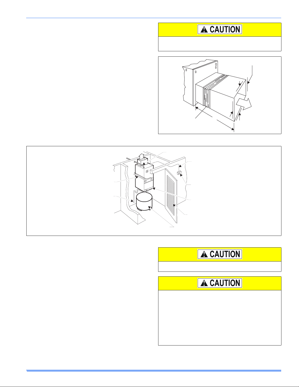
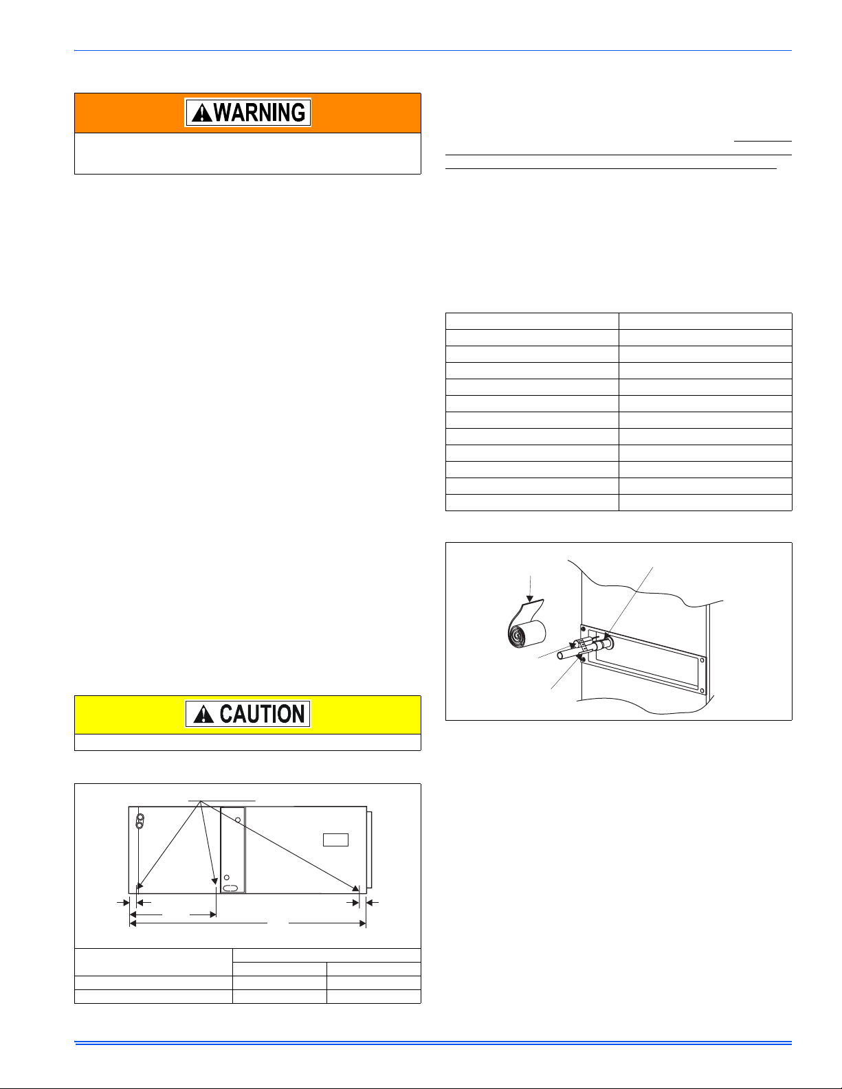
If electric heat is used, a minimum clearance of 1” must be maintained on all sides of the supply air duct and/or plenum continuously
for up to 3’ (See Figure 1).
MINIMUM CLEARANCE
OF 1” ALL SIDES
POWER WIRING
TO MAIN
POWER SOURCE
REFRIGERANT
LINES
TO
CONDENSATE
DRAIN
SUPPLY
AIR
ELECTRIC HOT WATER HEATER
(Must comply with water heater installation instructions)
FIGURE 2: Typical Installation
HORIZONTAL DRAIN PAN CONVERSION
These air handler units are supplied ready to be installed in a right hand
horizontal position. If unit requires left hand positioning, the unit must
have the pan installed in the correct position.
1. Remove blower access, coil access, and center access panels.
NOTE: Conversion must be made before brazing the refrigerant con-
nections to the coil.
2. See Figure 3, remove two screws from horizontal drain pan, to
remove pan from position “3A” if factory installed.
3. Position horizontal pan, as required in either “A” or “B” position,
locking it into the vertical drain pan as shown.
4. Horizontal drain pans have 4 plugged drains. Remove plugs from
connections being used.
NOTE: If this step is overlooked, it can lead to a water problem later.
5. Use removed plug to plug primary of upflow drain pan.
6. Attach horizontal pan with 2 screws removed in step no. 2 or supplied with the unit. Ensure that the drain pan is lying flat against the
insulation of the cabinet.
7. Horizontal drain cutout in the center access panel should be
removed by using a utility knife (if not previously cut out).
8. Re-position and replace access panels.
FLEXIBLE
DUCT COLLAR
3’
FIGURE 1: Plenum Clearances
POWER WIRING
CONTROL
WIRING
THERMOSTAT
FILTER
ACCESS
LOUVERED
DO NOT TRY TO KNOCK OUT PANEL OPENING FOR SECONDARY DRAIN PAN. SEE ITEM 7.
Models F*FP045,048,060 have a coil baffle and support bracket
factory installed for right hand horizontal application (refer to Figure
3C). For left hand applications the coil support bracket must be
moved to the right side of the coil, and the coil baffle must be
rotated to avoid water blow-off.
To rotate baffle, remove the coil assembly from the unit (remove
front two screws holding the coil support bracket and the two
screws holding the drain pan). Remove four screws in coil baffle
and remove the coil baffle and rotate ends.
Resecure the baffle and reinstall the coil assembly ensuring that
the rear of the drain pan is secured under the back flange of the
unit. Reinstall the coil support bracket on the right side of the coil.
Unitary Products Group 3
Page 4
292043-UIM-B-0707
BLOWER
COMPARTMENT
(ACCESS PANEL
REMOVED)
PRIMARY
DRAIN
SECONDARY
DRAIN
HORIZONTAL
DRAIN PAN
POSITION "B”
VERTICAL
DRAIN PAN
SECONDARY
DRAIN UPFLOW
3/4" THREADED
DUCT WORK MAY BE FASTENED
CAUTIOUSLY WITH SCREWS TO
THE SIDES AND REAR OF UNIT
4A - FRONT VIEW
BLOWER
HOUSING
FILTER
PRIMARY DRAIN UPFLOW
3/4” THREADED
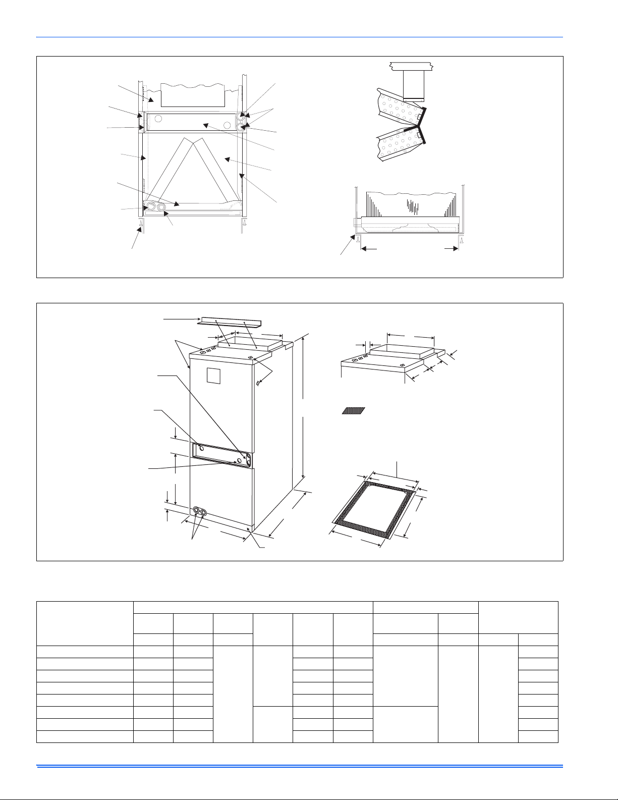
FIGURE 3: Filter Access & Drain Pan Conversion / Coil Baffle
SHIPPING BRACKET*
REMOVE PRIOR TO
INSTALLATION (2 SCREWS)
10-3/8
J
DRAIN CONNECTIONS
FOR HORIZONTAL
APPLICATIONS
PRIMARY
DRAIN
3/4" PVC SOCKETS
FOR HORIZONTAL
DRAIN APPLICATION
SECONDARY
DRAIN
CENTER ACCESS PANEL
COIL COMPARTMENT
(ACCESS PANEL REMOVED)
HORIZONTAL
DRAIN PAN
POSITION "A”
"S" BRACKET MUST BE USED TO
FASTEN DUCT WORK TO FRONT OF UNIT
ALL DIMENSIONS ARE IN INCHES. THEY ARE SUBJECT TO CHANGE
WITHOUT NOTICE. CERTIFIED DIMENSIONS WILL BE PROVIDED
F
K
UPON REQUEST.
SUPPORT
BRACKET
060 COIL BAFFLE
(SHOWN IN
RIGHT-HORIZONTAL
POSITION)
4C - FRONT VIEW
4B - SIDE VIEW
FILTER
RETURN AIR DUCT
3/4
TOP VIEW (ALL MODELS)
F
7-1/2
4-1/8
10-3/8
VAPOR
OPENING
LIQUID
OPENING
2
DRAIN CONNECTIONS
FOR UPFLOW APPLICATIONS
FIGURE 4: Dimensions & Duct Sizes
TABLE 1:
Dimensions
MODELS F*FP
ABC
Height Width Depth Power Control Liquid Vapor
024 40-3/4 18
030 40-3/4 18 14-7/8 16-1/2 3/4
036 40-3/4 21-1/2 18-3/8 20 3/4
040 40-3/4 21-1/2 18-3/8 20 7/8
042 40-3/4 21-1/2 18-3/8 20 7/8
045 50-3/4 24
048 50-3/4 24 20-7/8 22-1/2 7/8
060 50-3/4 24 20-7/8 22-1/2 7/8
A
4
D
C
B
FILTER
ACCESS
=DRAIN PAN FOOTPRINT
MAX. FILTER LENGTH
(21 INCHES)
MAX. FILTER WIDTH
(B MINUS 1-1/2 INCHES)
3/4
REAR
18-3/8
E
BOTTOM VIEW
3/4
Dimensions Wiring K.O.’s* Refrigerant
Connections
Line Size
5/8
7/8
22
DEF
14-7/8 16-1/2
12-1/8
20-7/8 22-1/2
17-3/8
JK
7/8 (1/2)
1-3/8 (1)
7/8 (1/2) 3/8
7/8 (1/2)
1-3/8 (1),
1-23/32 (1-1/4)
4 Unitary Products Group
Page 5
292043-UIM-B-0707
DUCT CONNECTIONS
Use 1/2" screws to connect ductwork to bottom of unit. Longer
screws will pierce the drain pan and cause leakage. If pilot holes
are drilled, drill only though field duct and unit bottom flange.
NOTE: The electric heat accessory should be installed before the supply air duct is attached to the supply air openings. Refer to the electric
heater kit instructions for proper installation.
Air supply and return may be handled in one of several ways best
suited to the installation. See Figure 4 for dimensions for duct inlet and
outlet connections.
The vast majority of problems encountered with combination heating
and cooling systems can be linked to improperly designed or installed
duct systems. It is therefore highly important to the success of an installation that the duct system be properly designed and installed.
Use flexible duct collars to minimize the transmission of vibration/noise
into the conditioned space. If electric heat is used, non-flammable
material must be used.
Where return air duct is short, or where sound may be a problem,
sound absorbing glass fiber should be used inside the duct. Insulation
of duct work is a must where it runs through an unheated space during
the heating season or through an uncooled space during the cooling
season. The use of a vapor barrier is recommended to prevent absorption of moisture from the surrounding air into the insulation.
The supply air duct should be properly sized by use of a transition to
match unit opening. All ducts should be suspended using flexible hangers and never fastened directly to the structure. This unit is not
designed for non-ducted (freeblow) applications. Size outlet plenum or
transition to discharge opening sizes shown in Figure 4.
Duct work should be fabricated and installed in accordance with local
and/or national codes. This includes the standards of the National Fire
Protection Association for Installation of Air-Conditioning and Ventilating Systems, NFPA No. 90B.
A suspension kit is available. Models 1BH0601 (unit sizes 018-060) is
designed specifically for the units contained in this instruction (upflow
application only). For installation of these accessory kits, see the
instructions packed with the kit.
For suspension of these units in horizontal applications, it is recommended to use angle steel support brackets with threaded rods, supporting the units from the bottom, at the locations shown in Figure 5.
COIL METERING DEVICES
The coil in this Air Handler unit will have a TXV metering device
installed at the factory.
The model number will have the following format:
F*FPxxxH06T2y - The coil will have a Thermal Expansion Valve (TXV)
installed. The y character specifies which TXV is installed at the factory.
Please refer to the TXV Metering Device section for installation notes.
.
TABLE 2:
TXV Metering Device
Installed TXV Sizes
Indoor Coil Model Metering Device
F4FP024H06T2A TXV 2A
F4FP024H06T2B TXV 2B
F4FP030H06T2A TXV 2A
F4FP036H06T2A TXV 2A
F4FP040H06T2A TXV 2A
F4FP040H06T2C TXV 2C
F4FP042H06T2A TXV 2A
F4FP042H06T2C TXV 2C
F4FP045H06T2C TXV 2C
F5FP048H06T2C TXV 2C
F5FP060H06T2C TXV 2C
EXPANSION
INSULATION
ROLL
BULB TUBING
AIR FILTERS
Air filters must be field supplied. A 1" filter access rack has been built
into the unit. See Figure 4. Remove filter access cover shown. Install
proper size filter. Standard 1" size permanent or throw away filter may
be used, or, permanent washable filters are available using model numbers: 1PF0601, 602, 603BK. See Table 3 for filter size.
Equipment should never be operated without filters.
SUSPENSION KITS
SUSPENSION SUPPORT LOCATIONS FOR HORIZONTAL APPLICATIONS*
2
WW
NOTE: USE SUPPORTS UNDER UNIT.
XX
Units
(Nominal Tons)
WW XX
018, 024, 030, 036, 040, 042 14” 40-3/4”
045, 048, 060 19-1/2” 50-3/4”
FIGURE 5: Typical Horizontal Installation
1-1/2
Dimension
EXPANSION
BULB
EXPANSION
BULB CLAMP
FIGURE 6: TXV Bulb Installation
Please refer to Table 2 to verify which TXV is installed in this Air Handler unit and that this AHU is a valid system match for the AC or HP unit
installed.
The TXV is bolted into the coil assembly of this Air Handler unit at the
factory. The temperature sensing bulb will need to be attached to the
coil suction header line after the line set is brazed to the coil.
• Make sure the TXV bulb is outside of the Air Handler cabinet.
Excess tubing should remain inside the cabinet.
• Take caution not to apply high temperatures to the TXV assembly
or equalizer line while brazing.
• Attach field line sets and braze to coil connections. Replace
access panels & secure.
• Secure the TXV bulb to the suction line with the clamp provided.
Choose a horizontal location as close to the cabinet as possible,
but not directly on the brazed connection joint. Refer to Figure 7.
• The bulb should be in direct contact with the coil suction line
along the length of the bulb.
Unitary Products Group 5
Page 6
292043-UIM-B-0707
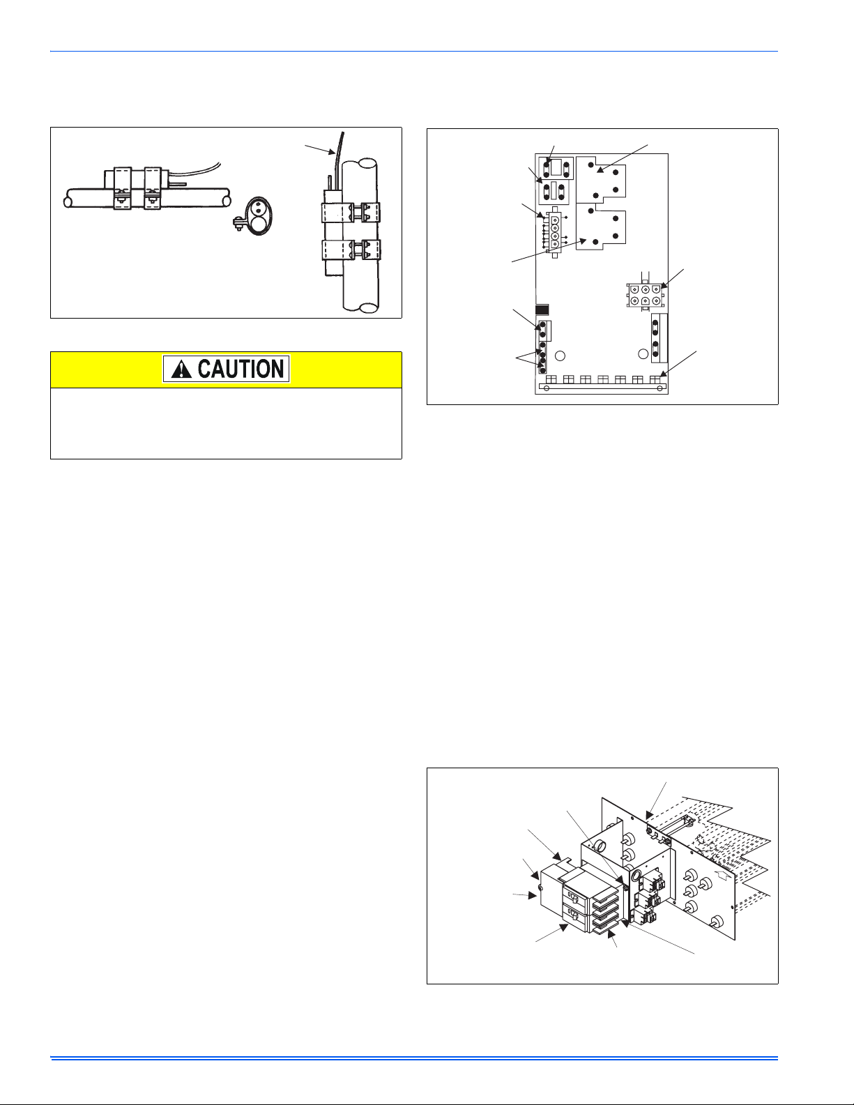
• If the suction line is 3/4" diameter - position the bulb near the top
of the copper tube as shown. If the tube is 7/8" diameter - position
the bulb near the bottom of the tube. Refer to Figure 7.
• Wrap the clamp, bulb & line securely with insulation provided.
TAIL
END
UP
*
ROTATE BULB TO KEEP
TAILAT BOTTOM
VERTICAL
RISER
FIGURE 7: Bulb Location
COIL UNDER PRESSURE.
Relieve pressure by removing plug from piping connection. Coil will
have factory installed TXV. See outdoor unit documentation for correct TXV to be used. Refer to unit nameplate for TXV identification
for this unit.
NOTE: The coil should be open to the air for no more than 2 minutes to
keep moisture and contaminates from entering the system. If the coil
cannot be brazed into the refrigeration system in that time, the ends
should be temporarily closed or plugged. For a short term delay, use
masking tape over the ends of the copper tubing to close the tube to the
air. For a longer term delay, use plugs or caps. There is no need to
purge the coil if this procedure is followed.
REFRIGERANT LINE CONNECTION
See the outdoor unit installation instructions for the procedure to install
field supplied tubing for systems with sweat fittings.
Stub adapters are available to adapt sweat connections to quick connections.
Connect lines as follows:
NOTE: Route the refrigerant lines to the coil in a manner that will not
obstruct service access to the coil, air handling system or filter.
1. Suction line connections are made outside the center access
panel. Center access panel is recessed to assure sufficient room
for brazing or it can be removed and slid over the suction line during brazing.
2. Plan for TXV bulb placement.
3. Remove rubber plugs from refrigerant lines.
4. Braze the suction line. Re-attach the center access panel, if it had
been removed.
5. Braze the liquid line.
6. Install supplied grommets on both the suction and liquid lines to
complete the air seal.
7. See previous section for TXV bulb.
Lines should be sound isolated by using the appropriate hangers or
strapping.
When field supplied lines are used be sure to insulate the suction line
only.
ELECTRIC HEATERS & OPERATING CONTROLS
The low voltage transformer and fan / heater control, are standard on all
models. See Figure 8. The air handlers are shipped pre-wired to operate as cooling only applications. To complete the installation for cooling
only, install the 6-pin jumper plug to the control board to bypass the
heater limit controls. This jumper plug is secured to the duct cover near
the 4-pin power plug harness. Failure to install the plug will cause the
blower to run continuously. (See Figure 8).
T9A
T9A
W2
FAN RELAY
LIM
&
FAN
HEAT
&
COM
LIM
PWR
HEAT2
DRV
HEAT3
DRV
O C
W1
6-PIN CONNECTOR
(LIMIT, 2ND, 3RD
& 4TH HEAT RELAY
DRIVER)
TEST
HEAT4
DRV
2 SPEED LTRIPECM
24 VOLT
COMMON
TRANSFORMER
CONNECTIONS
(HIGH VOLTAGE)
4-PIN POWER
CONNECTOR
1 STAGE
HEAT RELAY
24 VOLT R
5 AMP
CONTROL
VOLTAGE
FUSE
FAN CONNECTIONS
F
L
A
L
1
N
2
K2
L
L
2
1
1
L2
K1
2
H
3
L
L
4
BREAK TAB FOR
VARIABLE SPEED MOTOR
2
4
V
A
C
5
A
M
P
M
A
X
Y
R
G
FIGURE 8: Control Board
Mark the unit nameplate with the appropriate heater selection on the
space provided or NONE to indicate cooling only . To operate these unit s
with electric heat, it is necessary to field install an electric heater kit
(2HK). See Electric Heater Kit Accessory Installation instructions for
proper installation procedure. Prior to installing electric heat, it is necessary to perform the following procedure:
1. Remove the 4-pin power plug from the control board (See Figure
8).
NOTE: This pin must not be used when electric heaters are installed.
2. Remove the four (4) screws from the duct cover and remove the
duct cover from the air handler.
Right-hand Airflow Application Only - Models with Circuit
Breakers - See Figure 9
If unit is to be installed for right hand air flow, the circuit breakers in the
heat kit will need to be removed and rotated 180°, so the OFF position
will be down when the cabinet is positioned on the right side. This is an
NEC requirement. Do One Breaker At A Time - to make sure wires
are reconnected properly. Loosen terminal screws on the wires and
gently pull the wires back from the breaker. Remove screws securing
the breaker plate and rotate 180°, then secure the breaker plate and
reconnect the wires to the breaker. Proper torque for terminal screws is
35 in/lbs.
REMOVE 3 SCREWS TO
REMOVE THE CIRCUIT
BREAKER BRACKET
FROM HEAT KITASSEMBLY
JUMPER BAR
JUMPER BAR COVER
FIELD SUPPLY WIRING
WILL BE ATTACHED TO
THIS SIDE OF THE
CIRCUIT BREAKER(S)
CIRCUIT BREAKER(S) - THERE
MAY BE ONE, TWO OR THREE
HEAT KIT WIRING WILL BE
ATTACHED TO THIS SIDE OF
THE CIRCUIT BREAKER(S)
FIGURE 9: Electric Heaters in Horizontal Configuration - Right Hand
Air Flow
HEAT KITASSEMBLY
CIRCUIT
BREAKER
BRACKET
AIR FLOW
6 Unitary Products Group
Page 7

292043-UIM-B-0707
Unitary Products Group 7
Page 8

292043-UIM-B-0707
LOW V OLTAGE CONTROL CONNECTION
The 24 volt power supply is provided by an internally wired low voltage
transformer which is standard on all models. However, if the unit is connected to a 208 volt power supply the low voltage transformer must be
rewired to the 208 volt tap. See the unit wiring label.
Field supplied low voltage wiring can exit the unit on the top right hand
corner or the right hand side panel (see Fig. 5, item K).
Install a 7/8" plastic bushing in the selected hole and keep low voltage
wiring as short as possible inside the control box.
The field wiring is to be connected at the screw terminals of the control
board. Refer to Figure’s 12 and 13.
NOTE: All wiring must comply with local and national electrical code
requirements. Read and heed all unit caution labels.
TYPICAL WIRING WITHOUT ELECTRIC HEAT
GND. LUG
POWER
SUPPLY
1 PHASE ELECTRIC HEAT
WITH CIRCUIT BREAKER
& BREAKER BAR REMOVED
MULTI-SOURCE (15 - 25 KW) - 25 KW SHOWN
GND. LUG
POWER
SUPPLY 1
POWER
SUPPLY 2
POWER
SUPPLY 3
GND.
LUG
GND.
LUG
WITHOUT CIRCUIT BREAKER
GND. LUG
POWER
SUPPLY
WITHOUT CIRCUIT BREAKER
SINGLE SOURCE (2.5 - 10 KW)
GND. LUG
POWER
SUPPLY
NOTE: It is possible to vary the amount of electric heat turned on during
the defrost cycle of a heat pump. Standard wiring will only bring on 5
KW of electric heat during defrost see T able 6 and Figures 12 and 13 for
alternate staging.
LINE POWER CONNECTIONS
Power may be brought into the unit through the supply air end of the
unit (top when unit is vertical) or the left side panel. Use the hole appropriate to the unit's orientation in each installation to bring conduit from
the disconnect. The power lead conduit should be terminated at the
electrical control box. Refer to Tables 4, 8 & 10 for wire requirements.
Also see Figure 10.
ELECTRIC HEAT
3 PHASE (10 - 15 KW)
ELECTRIC HEAT
GND.
LUG
GND.
LUG
POWER
SUPPLY
1 PHASE ELECTRIC HEAT
WITH CIRCUIT BREAKER
AS SHIPPED FROM FACTORY
SINGLE SOURCE
(2.5 - 25 KW) - 25 KW SHOWN
GND. LUG
POWER WIRING (208/230-1-60)
NOTE: USE ONLY COPPER CONDUCTORS
GND.
LUG
FIGURE 10: Line Power Connections
BLOWER SPEED CONNECTIONS
Except for F4FP045, which has a 4-speed motor, and F5FP* which has
a 5-speed high efficiency X-13 motor, all air handlers contain three
speed blower motors which are pre-wired to the control board.
Adjust blower motor speed to provide airflow within the minimum and
maximum limits approved for evaporator coil, electric heat and outdoor
unit. Speed tap adjustments are made at the motor terminal block, See
Figure 11. Airflow data is shown in Tables 6 and 11.
TO
RELAY
BLU
YEL
208 / 230V
FAN MOTOR
4-5 TON HIGH EFFICIENCY MOTOR (X-13)
BLK
GRN
C
G
L
N
PUR
BLOWER
1
2
3
4
5
TO CONTROL
BOARD C
(Common)
GRN
YEL
TRANSFORMER
Higher efficiencies will be obtained if the indoor air volume is as high as
possible provided the CFM does not exceed limitations and the sound
level is not objectionable.
Connect motor wires to motor speed tap receptacle for speed desired.
See wiring label for motor wiring details. See Figure 11.
The unit control is designed for the addition of a two speed fan kit. See
accessory kit for details.
1-1/2 TON TO 4 TON STANDARD MOTOR
FACTORY WIRED TO
TRANSFORMER
TO
230V
YEL
FACTORY WIRED TO
FAN MOTOR RELAY
TERMINAL ON
CONTROL BOARD
230 VOLT
BLOWER MOTOR
CAP
BRN
HIGH
MED
LOW
GND.
PUR
PUR
FIGURE 11: Blower Speed Connections
8 Unitary Products Group
Page 9
292043-UIM-B-0707
TABLE 3:
Physical and Electrical Data
Models F*FP 024 030 036 040
Blower - Diameter x Width 10 x 6 10 x 8 10 x 8 10 x 8
Motor
HP 1/4 1/3 1/2 1/3
Nominal RPM 1075 1075 1075 1075
Voltage 208/230
Amps
Full Load (208/230) 1.6/1.4 (50 Hz:2.1) 2.5 / 2.2 3.3/2.9 (50 Hz:2.3) 2.5 / 2.2
Locked Rotor (208/230) 3.3 / 2.9 6.2 / 5.5 7.4 / 6.5 6.2 / 5.5
Type DISPOSABLE OR PERMANENT
Filter
1
Size 16 x 20 x 1 16 x 20 x 1 20 x 20 x 1 20 x 20 x 1
Permanent Type Kit 1PF0601BK 1PF0601BK 1PF0602BK 1PF0602BK
Shipping / Operating Weight (lbs.) 98 / 93 105 / 100 115 / 109 121 / 115
Models F*FP 042 045 048 060
Blower - Diameter x Width 10x8 10x10 11x10 11x10
Motor
HP 3/4 1/3 1.0 1.0
Nominal RPM 1130 925 1050 1050
Voltage 208/230 230
Amps
Full Load (208/230) 4.4/3.8 3.0/2.7 7.6 7.6
Locked Rotor (208/230) 11.9/10.3 4.8/4.1 – –
Type DISPOSABLE OR PERMANENT
Filter
1
Size 20 x 20 x 1 22 x 20 x 1 22 x 20 x 1 22 x 20 x 1
Permanent Type Kit 1PF0602BK 1PF0603BK 1PF0603BK 1PF0603BK
Shipping / Operating Weight (lbs.) 121/115 150/144 153/147 160/154
1. Field Supplied
TABLE 4:
Electrical Data - Cooling Only (50 & 60 Hz)
Total Motor Amps Minimum Circuit Ampacity
Models F*FP
60 Hertz 60 Hertz
208V 240V 208V 240V
Max. O.C.P.
Amps/Type
1
Minimum Wire
Size A.W.G.
024 1.6 1.5 2.0 1.8 15 14
030 2.5 2.3 3.2 2.8 15 14
036 3.3 3.0 4.2 3.7 15 14
040 2.5 2.3 3.2 2.8 15 14
042 4.4 4.0 5.5 4.8 15 14
045 3.1 2.6 3.9 3.4 15 14
048 7.6 7.6 9.5 9.5 15 14
060 7.6 7.6 9.5 9.5 15 14
1. OCP = Over Current Protection device, must be HACR type Circuit Breaker or Time Delay fuse.
TABLE 5:
Conversion Table
KW & MBH Conversions - for Total Power Input Requirement
FOR
208V
230V 240V .918
OPERATION MULTIPLY
240V
.751
TABULATED KW & MBH BY
220V 240V .840
Unitary Products Group 9
Page 10

292043-UIM-B-0707
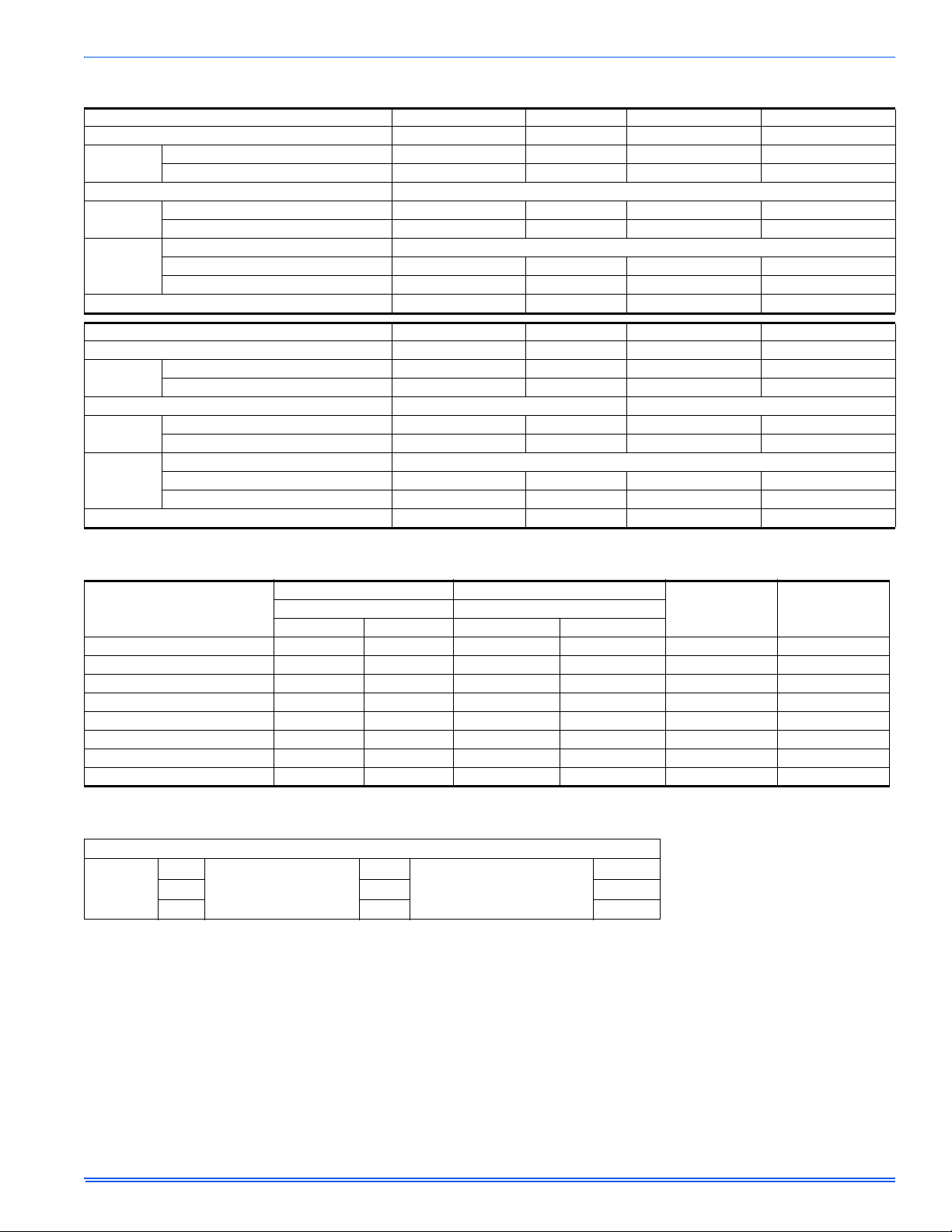
TABLE 6:
Models F*FP
Electrical Data - 1 Ø - 208/230-1-60
Heater*
Model
1
Max. Static
& Min. CFM
Static Tap 208V 240V 208V 240V 208V 240V 208V 240V 208V 240V
024
2HK*6500506B
2HK*6500806B Low 5.6 7.5 19.1 25.6 3.8 5.0 5.6 7.5 5.6 7.5
0.5
Low 3.8 5.0 13.0 17.1 3.8 5.0 3.8 5.0 3.8 5.0
2HK*6501006B Low 7.5 10.0 25.6 34.1 3.8 5.0 7.5 10.0 7.5 10.0
030
2HK*6500506B
2HK*6500806B Low 5.6 7.5 19.1 25.6 3.8 5.0 5.6 7.5 5.6 7.5
2HK*6501006B Low 7.5 10.0 25.6 34.1 3.8 5.0 7.5 10.0 7.5 10.0
0.5
Low 3.8 5.0 13.0 17.1 3.8 5.0 3.8 5.0 3.8 5.0
2HK16501506B HI 11.3 15.0 38.6 51.2 3.8 5.0 7.5 10.0 11.3 15.0
036
2HK*6500506B
2HK*6500806B Low 5.6 7.5 19.1 25.6 3.8 5.0 5.6 7.5 5.6 7.5
2HK*6501006B Low 7.5 10.0 25.6 34.1 3.8 5.0 7.5 10.0 7.5 10.0
0.5
Low 3.8 5.0 13.0 17.1 3.8 5.0 3.8 5.0 3.8 5.0
2HK16501506B Med 11.3 15.0 38.6 51.2 3.8 5.0 7.5 10.0 11.3 15.0
4
0.5 High 13.2 17.6 45.1 60.1 2.8 3.8 10.4 13.8 13.2 17.6
Low 3.8 5.0 13.0 17.1 3.8 5.0 3.8 5.0 3.8 5.0
0.5
040
2HK16501906B
2HK*6500506B
2HK*6500806B Low 5.6 7.5 19.1 25.6 3.8 5.0 5.6 7.5 5.6 7.5
2HK*6501006B Low 7.5 10.0 25.6 34.1 3.8 5.0 7.5 10.0 7.5 10.0
2HK16501506B High 11.3 15.0 38.6 51.2 3.8 5.0 7.5 10.0 11.3 15.0
042
2HK*6500506B
2HK*6500806B Low 5.6 7.5 19.1 25.6 3.8 5.0 5.6 7.5 5.6 7.5
2HK*6501006B Low 7.5 10.0 25.6 34.1 3.8 5.0 7.5 10.0 7.5 10.0
0.5
Low 3.8 5.0 13.0 17.1 3.8 5.0 3.8 5.0 3.8 5.0
2HK16501506B Low 11.3 15.0 38.6 51.2 3.8 5.0 7.5 10.0 11.3 15.0
045
2HK*6500506B
2HK*6500806B Low 5.6 7.5 19.1 25.6 3.8 5.0 5.6 7.5 5.6 7.5
2HK*6501006B Med 7.5 10.0 25.6 34.1 3.8 5.0 7.5 10.0 7.5 10.0
0.5
Low 3.8 5.0 13.0 17.1 3.8 5.0 3.8 5.0 3.8 5.0
2HK16501506B High 11.3 15.0 38.6 51.2 3.8 5.0 7.5 10.0 11.3 15.0
2HK*6500506B
Med Low
2HK*6500806B Med Low 5.6 7.5 19.1 25.6 3.8 5.0 5.6 7.5 5.6 7.5
048
2HK*6501006B Med Low 7.5 10.0 25.6 34.1 3.8 5.0 7.5 10.0 7.5 10.0
2HK16501506B Med Low 11.3 15.0 38.6 51.2 3.8 5.0 7.5 10.0 11.3 15.0
0.5
2HK16502006B Med Low 15.0 20.0 51.2 68.3 3.8 5.0 11.3 10.0 15.0 20.0
2HK16502506B Med Low 18.8 25.0 64.2 85.3 3.8 5.0 11.3 15.0 18.8 25.0
2HK*6500506B
Med
2HK*6500806B Med 5.6 7.5 19.1 25.6 3.8 5.0 5.6 7.5 5.6 7.5
060
2HK*6501006B Med 7.5 10.0 25.6 34.1 3.8 5.0 7.5 10.0 7.5 10.0
2HK16501506B Med 11.3 15.0 38.6 51.2 3.8 5.0 7.5 10.0 11.3 15.0
0.5
2HK16502006B Med 15.0 20.0 51.2 68.3 3.8 5.0 7.5 10.0 15.0 20.0
2HK16502506B Med 18.8 25.0 64.2 85.3 3.8 5.0 11.3 15.0 18.8 25.0
1. Heat amps shown at 240V represents maximum heater rating.
2. See conversion Table 5.
3. If first stage heat or 66 is connected to W1, otherwise refer to this table.
4. 2HK16501906B only applies to F4FP036 model.
* May be 0 (no breaker) or 1 (with breaker).
Total Heat
2
KW Staging
3
KW MBH W1 Only W2 Only W1 + W2
3.8 5.0 13.0 17.1 3.8 5.0 3.8 5.0 3.8 5.0
3.8 5.0 13.0 17.1 3.8 5.0 3.8 5.0 3.8 5.0
10 Unitary Products Group
Page 11

292043-UIM-B-0707
TABLE 7:
Electrical Data - (For
Models F*FP
Single Source
Heater*
Model
Power Supply) - Copper Wire 1 Ø - 208/230-1-60
Heater
Amps
240V
Min. Circuit Ampacity
208V 240V 208V 240V 208V 240V
2HK*6500506B 20.8 24.7 27.7 25 30 10 10
024
2HK*6500806B 31.3 35.5 40.7 40 45 8 8
2HK*6501006B 41.7 46.9 53.7 50 60 8 6
2HK*6500506B 20.8 25.8 28.7 30 30 10 10
030
2HK*6500806B 31.3 36.7 41.7 40 45 8 8
2HK*6501006B 41.7 48.1 54.7 50 60 8 6
2HK16501506B 62.5 70.9 80.8 80 90 4 3
2HK*6500506B 20.8 26.8 29.5 30 30 10 10
2HK*6500806B 31.3 37.7 42.6 40 45 8 8
036
2HK*6501006B 41.7 49.1 55.6 50 60 8 6
2HK16501506B 62.5 71.9 81.6 80 90 4 3
2HK16501906B
3
73.3 83.3 95.2 90 100 3 3
2HK*6500506B 20.8 25.8 28.7 30 30 10 10
040
2HK*6500806B 31.3 36.7 41.7 40 45 8 8
2HK*6501006B 41.7 48.1 54.7 50 60 8 6
2HK16501506B 62.5 70.9 80.8 80 90 4 3
2HK*6500506B 20.8 28.1 30.5 30 35 10 8
042
2HK*6500806B 31.3 38.9 43.6 40 45 8 8
2HK*6501006B 41.7 50.3 56.6 60 60 6 6
2HK16501506B 62.5 73.2 82.6 80 90 4 3
2HK*6500506B 20.8 26.6 29.3 30 30 10 10
045
2HK*6500806B 31.3 37.4 42.3 40 45 8 8
2HK*6501006B 41.7 48.8 55.3 50 60 8 6
2HK16501506B 62.5 71.7 81.4 80 90 4 3
2HK*6500506B
20.8 32.8 35.6 35 40 8 8
2HK16500806B 31.3 43.0 48.4 45 50 8 8
048
2HK16501006B 41.7 55.3 61.5 60 70 6 4
2HK16501506B 62.5 77.3 87.8 80 90 4 3
2HK16502006B 83.3 101.0 113.8 110 125 2 1
2HK16502506B 104.2 124.3 139.9 125 150 1 1/0
2HK*6500506B
20.8 32.8 35.6 35 40 8 8
2HK16500806B 31.3 42.9 48.3 45 50 8 8
060
2HK16501006B 41.7 55.3 61.6 60 70 6 4
2HK16501506B 62.5 78.5 87.8 80 90 4 3
2HK16502006B 83.3 101.0 113.8 110 125 2 1
2HK16502506B 104.2 122.2 139.5 125 150 1 1/0
1. Heat amps shown at 240V represents maximum heater rating.
2. O.C.P. = Over Current Protection device, must be HACR type Circuit Breaker or Time Delay fuse.
3. 2HK16501906B only applies to F4FP036 model.
* May be 0 (no breaker) or 1 (with breaker).
TABLE 8:
Electrical Data - (For
Models F*FP
Multi-Source
Heater
Model
Power Supply) - Copper Wire 1 Ø - 208/230-1-60
Min. Circuit Ampacity
Max. O.C.P.
Circuit Circuit Circuit
1st 2nd 3rd 1st 2nd 3rd 1st 2nd 3rd
208/240 208/240 208/240 208/240 208/240 208/240 208/240 208/240 208/240
030
036
2HK16501506B 25.8/28.7 45.1/52.1 — 30/30 50/60 — 10/10 8/6 —
2HK16501506B 26.8/29.5 45.1/52.1 — 30/30 50/60 — 10/10 8/6 —
2
2HK16501906B
38.3/42.6 45.7/52.6 — 40/45 50/60 — 8/8 8/6 —
040 2HK16501506B 25.8/28.7 45.1/52.1 — 30/30 50/60 — 10/10 8/6 —
042 2HK16501506B 28.1/30.5 45.1/52.1 — 30/35 50/60 — 10/8 8/6 —
045 2HK16501506B 26.6/29.3 45.1/52.1 — 30/30 50/60 — 10/10 8/6 —
2HK16501506B 32.8/35.6 45.1/52.1 — 35/40 50/60 — 8/8 8/6 —
048
2HK16502006B 55.3/61.6 45.1/52.1 — 60/70 50/60 — 6/4 8/6 —
2HK16502506B 32.8/35.6 45.1/52.1 45.1/52.1 35/40 50/60 50/60 8/8 8/6 8/6
2HK16501506B 32.8/35.6 45.1/52.1 — 35/40 50/60 — 8/8 8/6 —
060
2HK16502006B 55.3/61.6 45.1/52.1 — 60/70 50/60 — 6/4 8/6 —
2HK16502506B 33.8/35.6 45.1/52.1 45.1/52.1 35/40 50/60 50/60 8/8 8/6 8/6
1. O.C.P. = Over Current Protection device, must be HACR type Circuit Breaker or Time Delay fuse.
2. 2HK16501906B only applies to F4FP036 model.
1
Field Wiring
Max. O.C.P.
1
1
Amps/Type
2
Amps/Type
75°C Wire Size - AWG
75°C Wire Size - AWG
Unitary Products Group 11
Page 12
292043-UIM-B-0707
TABLE 9:
TABLE 10:
Electrical Data - 3 Ø - 208/230-3-60
Models F*FP
024
030
036
040
042
045
048
060
1. Heat amps shown at 240V represents maximum heater rating.
2. Heaters are 3 Phase.
3. If first stage heat or 66 is connected to W1, otherwise refer to this table.
Electrical Data - (For
Models F*FP
024
030
036
040
042
045
048
060
1. Heat amps shown at 240V represents maximum heater rating.
2. Heaters are 3 Phase.
3. O.C.P. = Over Current Protection device, must be HACR type Circuit Breaker or Time Delay fuse.
Heater
Model
2HK06501025B 0.5 Low 7.5 10.0 25.6 34.1 3.8 5.0 7.5 5.0 7.5 10.0
2HK06501025B 0.5 Low 7.5 10.0 25.6 34.1 3.8 5.0 7.5 5.0 7.5 10.0
2HK06501525B 0.5 High 11.3 15.0 38.6 51.2 3.8 5.0 7.5 10.0 11.3 15.0
2HK06501025B 0.5 Low 7.5 10.0 25.6 34.1 3.8 5.0 7.5 5.0 7.5 10.0
2HK06501525B 0.5 High 11.3 15.0 38.6 51.2 3.8 5.0 7.5 10.0 11.3 15.0
2HK06501025B 0.5 Low 7.5 10.0 25.6 34.1 3.8 5.0 7.5 5.0 7.5 10.0
2HK06501525B 0.5 High 11.3 15.0 38.6 51.2 3.8 5.0 7.5 10.0 11.3 15.0
2HK06501025B 0.5 Low 7.5 10.0 25.6 34.1 3.8 5.0 7.5 5.0 7.5 10.0
2HK06501525B 0.5 Low 11.3 15.0 38.6 51.2 3.8 5.0 7.5 10.0 11.3 15.0
2HK06501025B 0.5 Med 7.5 10.0 25.6 34.1 3.8 5.0 7.5 5.0 7.5 10.0
2HK06501525B 0.5 High 11.3 15.0 38.6 51.2 3.8 5.0 7.5 10.0 11.3 15.0
2HK06501025B 0.5 Med Low 7.5 10.0 25.6 34.1 3.8 5.0 7.5 5.0 7.5 10.0
2HK06501525B 0.5 Med Low 11.3 15.0 38.6 51.2 3.8 5.0 7.5 10.0 11.3 15.0
2HK06501025B 0.5 Med 7.5 10.0 25.6 34.1 3.8 5.0 7.5 5.0 7.5 10.0
2HK06501525B 0.5 Med 11.3 15.0 38.6 51.2 3.8 5.0 7.5 10.0 11.3 15.0
Single Source
Heater
Model
2HK06501025B 41.2 46.5 45 50 8 8
2HK06501025B 42.2 47.4 45 50 8 8
2HK06501525B 42.2 47.4 45 50 8 8
2HK06501025B 43.1 48.2 45 50 8 8
2HK06501525B 43.1 48.2 45 50 8 8
2HK06501025B 42.2 47.4 45 50 8 8
2HK06501525B 42.2 47.4 45 50 8 8
2HK06501025B 44.2 49.1 45 50 8 8
2HK06501525B 44.2 49.1 45 50 8 8
2HK06501025B 42.8 47.9 45 50 8 8
2HK06501525B 42.8 47.9 45 50 8 8
2HK06501025B 48.3 53.9 50 60 8 6
2HK06501525B 48.3 53.9 50 60 8 6
2HK06501025B 48.3 53.9 50 60 8 6
2HK06501525B 48.3 53.9 50 60 8 6
1
2
Max. Static
& Min. CFM
Total Heat
KW MBH W1 Only W2 Only W1 + W2
Static Tap 208 240 208 240 208 240 208 240 208 240
Power Supply) - Copper Wire 3 Ø - 208/230-3-60
2
Min. Circuit Ampacity
208V 240V 208V 240V 208V 240V
Field Wiring
Max. O.C.P.
1
3
Amps/Type
KW Staging
3
75°C Wire Size - AWG
12 Unitary Products Group
Page 13

292043-UIM-B-0707
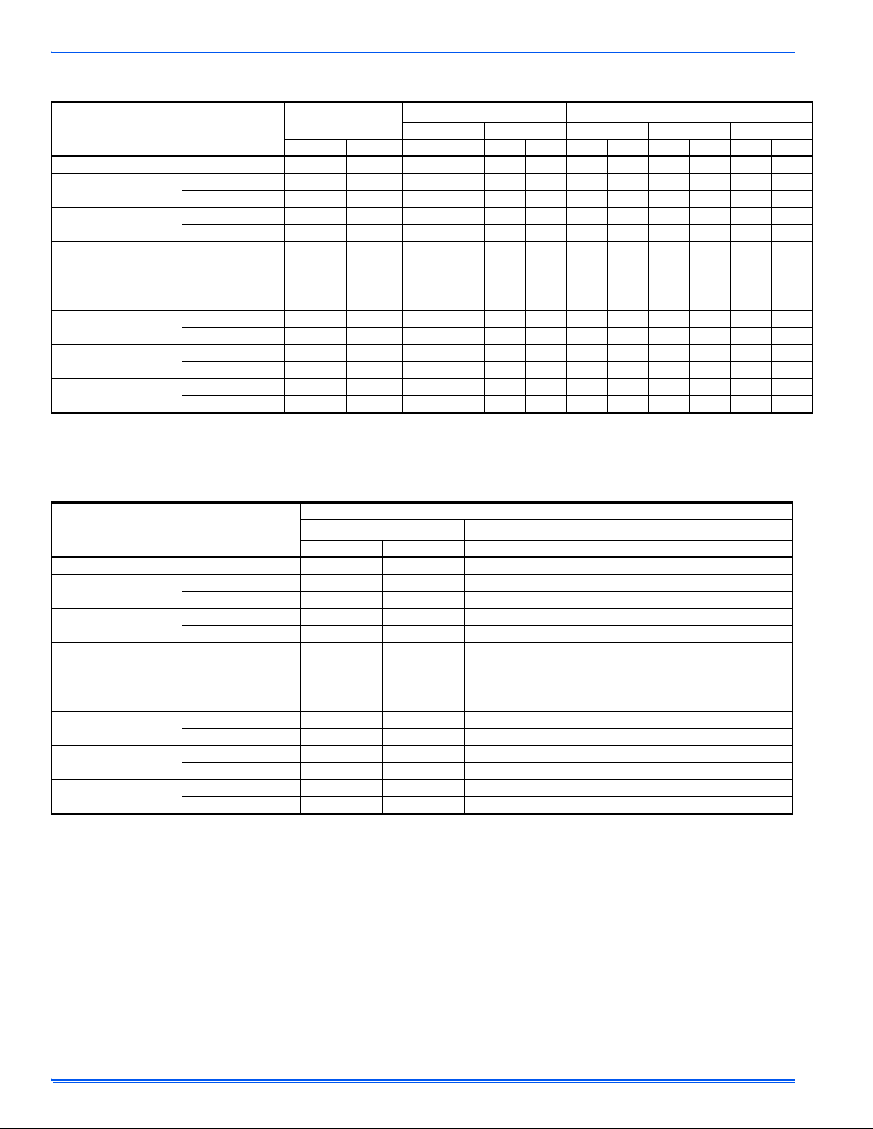
TABLE 11:
Airflow Data for 230 Volt - Heat Pump Models
Models
Blower Motor
Speed
0.10 0.20 0.30 0.40 0.50
High 950 910 865 835 775
F4FP024H06T2*
Med 845 815 785 745 705
Low 650 630 605 575 540
High 1,270 1,210 1,150 1,085 1,015
F4FP030H06T2*
Med 1,050 1,040 995 930 855
Low 855 820 780 735 680
High - 1,310 1,250 1,175 1,120
F4FP036H06T2*
Med 1,200 1,150 1,100 1,040 985
Low 1,060 1,015 970 925 860
High 1,270 1,210 1,150 1,085 1,015
F4FP040H06T2*
Med 1,050 1,040 995 930 855
Low 855 820 780 735 680
High - 1,575 1,500 1,420 1,350
F4FP042H06T2*
Med 1,460 1,395 1,330 1,260 1,190
Low 1,250 1,200 1,155 1,100 1,050
High 1,575 1,535 1,475 1,390 1,310
F4FP045H06T2*
Med High 1,375 1,315 1,255 1,185 1,110
Med Low 1,210 1,160 1,110 1,050 980
Low 1,035 990 940 890 825
High 2223 2158 2090 2029 1929
Med High 1948 1904 1801 1815 1777
F5FP048H06T2*
Med 1741 1690 1649 1606 1564
Med Low 1499 1454 1415 1370 1328
Low 1286 1233 1177 1142 1092
High 2195 2145 2070 2008 1920
Med High 1938 1899 1873 1824 1791
F5FP060H06T2*
Med 1726 1681 1641 1607 1560
Med Low 1525 1483 1441 1383 1356
Low 1306 1254 1204 1160 1114
High 2,285 2,195 2,105 2,015 1,950
F4FV060H06T2*
Med. 2,125 2,020 1,910 1,805 1,705
Low 1,655 1,605 1,550 1,500 1,450
NOTE: Air flow data shown above 0.50” W.C. external static pressure is for REFERENCE ONLY. Maximum allowab l e external static when electric heat is used is
limited to 0.50” W.C. Maximum allowable external static pressure may also be limited by minimum CFM requirements for proper Heat Pump operation.
1. Includes Return Air Filter and Largest Electric Heater.
All F*FP series air handler units are UL Listed up to 0.50" w.c. external static pressure, including air filter, wet coil, and largest KW size heater.
1
230 Volt
CFM @ External Static Pressure - IWC
0.60 0.70 0.80 0.90 1.00
730 662 590 502 400
654 594 524 439 344
508 450 383 285 158
946 862 769 645 502
804 714 624 494 364
624 550 447 333 190
1,053 983 894 779 645
933 879 795 711 587
809 740 661 572 453
946 802 769 645 502
804 714 624 494 364
624 550 447 333 190
1,273 1,192 1,102 996 871
1,125 1,052 960 842 695
1,001 931 851 751 631
1,245 1,147 1,030 897 735
1,040 944 848 732 606
921 844 737 640 533
770 698 616 524 432
1861 1788 1679 1594 1501
1741 1681 1618 1539 1453
1516 1476 1436 1387 1353
1269 1228 1191 1132 1093
1039 987 960 888 842
1852 1754 1663 1570 1462
1724 1679 1603 1521 1420
1517 1485 1433 1402 1349
1291 1253 1208 1169 1123
1061 1008 980 914 876
1,845 1,770 1,685 1,590 1,485
1,597 1,491 1,386 1,280 1,175
1,398 1,326 1,245 1,153 1,052
Unitary Products Group 13
Page 14

292043-UIM-B-0707
TABLE 12:
Airflow Data1 for 208 Volt - Heat Pump Models
208 Volt
Models
F4FP024H06T2*
F4FP030H06T2*
F4FP036H06T2*
F4FP040H06T2*
F4FP042H06T2*
F4FP045H06T2*
F5FP048H06T2*
F5FP060H06T2*
F4FV060H06T2*
NOTE: Air flow data shown above 0.50” W.C. external static pressure is for REFERENCE ONLY. Maximum allowable external static when electric heat is used is
limited to 0.50” W.C. Maximum allowable external static pressure may also be limited by minimum CFM requirements for proper Heat Pump operation.
1. Includes Return Air Filter and Largest Electric Heater.
All F*FP series air handler units are UL Listed up to 0.50" w.c. external static pressure, including air filter, wet coil, and largest KW size heater.
Blower Motor
Speed
CFM @ External Static Pressure - IWC
0.10 0.20 0.30 0.40 0.50
High 855 819 779 752 698
Med. 760 733 706 670 634
Low 585 567 545 518 486
High 1143 1089 1035 977 914
Med. 941 936 895 837 770
Low 770 738 702 662 612
High 1235 1179 1125 1058 1008
Med. 1080 1035 990 936 887
Low 954 914 873 833 774
High 1143 1089 1035 977 914
Med. 941 936 895 837 770
Low 770 738 702 662 612
High 1400 1418 1350 1278 1215
Med. 1314 1266 1197 1135 1071
Low 1125 1080 1040 990 945
High 1418 1382 1328 1251 1179
Med-high 1238 1184 1130 1067 999
Med-low 1089 1044 999 945 882
Low 932 891 846 801 743
High 2209 2140 2093 2000 1939
Med High 1945 1906 1871 1819 1784
Med 1739 1690 1640 1602 1559
Med Low 1506 1464 1415 1369 1325
Low 1301 1248 1197 1151 1095
High 2134 2124 2052 1979 1861
Med High 1916 1875 1838 1777 1744
Med 1716 1671 1613 1569 1523
Med Low 1494 1435 1390 1341 1284
Low 1276 1223 1168 1115 1068
High 2057 1976 1895 1814 1728
Med. 1913 1818 1719 1625 1535
Low 1490 1445 1395 1350 1305
0.60 0.70 0.80 0.90 1.00
657 596 531 452 360
589 535 472 395 310
457 405 344 257 142
851 776 692 581 451
724 643 562 445 328
561 495 402 300 171
947 885 804 701 580
840 791 716 640 528
728 666 595 515 408
851 776 692 581 451
724 643 562 445 328
561 495 402 300 171
1145 1073 991 897 784
1012 947 864 758 625
901 838 766 676 568
1120 1032 927 807 661
936 850 763 659 545
829 760 663 576 480
693 628 554 472 389
1864 1746 1724 1655 1587
1741 1667 1640 1595 1550
1516 1470 1431 1387 1343
1283 1238 1193 1139 1100
1054 1005 958 909 860
1756 1639 1597 1512 1427
1671 1594 1584 1537 1490
1475 1429 1384 1337 1290
1241 1194 1139 1087 1036
1009 965 902 847 792
1661 1593 1517 1431 1337
1437 1342 1247 1152 1057
1258 1194 1120 1038 946
14 Unitary Products Group
Page 15

FIGURE 12: Cooling Models with Electric Heat Wiring
THERMOSTAT
AIR HANDLER
BOARD
1-STAGE
AIR CONDITIONING
RR
W1
W2
C
W2
Y
C
HUMIDISTAT
Air Handler Control Wiring
Typical A/C - Cooling only Applications
Y
Y
G
G
W1
O
C
HUM
X
Y1
Y2
CFM selection
board only on
F4FV model
1
Air Handler Control Wiring
Typical A/C with Electric Heat Applications
THERMOSTAT
AIR HANDLER
BOARD
1-STAGE
AIR CONDITIONING
RR
W1
W2
C
W2
Y
C
HUMIDISTAT
Y
Y
G
G
W1
O
C
HUM
X
Y1
Y2
CFM selection
board only on
F4FV model
1
Field
Installed
Jumper If Required
NOTE:
Dehumidification
control connection
(”Humidistat” jumper on
CFM selection board
must be removed)
1
NOTE:
Dehumidification
control connection
(”Humidistat” jumper on
CFM selection board
must be removed)
1
F* SERIES F* SERIES
292043-UIM-B-0707
AIR HANDLER
THERMOSTAT
R
Y
G
E
W2
O
C
L
W1
CFM selection board
only on F4FV model
FIGURE 13: Single Stage Heat Pump Control Wiring
NOTES:
1. “Y” Terminal on Air Handler Control Board must be connected for full CFM and applications requiring 60 second Blower Off Delay for
SEER enhancement.
1
Optional Dehumidification Humidistat contacts open on rise.
2.
3. For F4FV model - Remove Humidistat Jumper on CFM Selection Board - if used.
4. For F4FV model - For Heat Pump Applications - Remove Heat Pump Jumper on CFM Selection Board.
5. To change quantity of heat during HP defrost cycle - Reverse connections at W1 and W2 on Air Handler Control Board.
BOARD
R
Y
G
W1
W2
O
C
HUM
X
Y1
Y2
HUMIDISTAT
1
NOTE:
Dehumidification control connection
(”Humidistat” jumper on CFM selection
board must be removed)
1
HEAT PUMP
R
Y
W1 Out
O
C
X/L
W
Unitary Products Group 15
Page 16

DRAIN CONNECTIONS
All drain lines should be trapped a minimum of three inches, should be
pitched away from unit drain pan and should be no smaller than the coil
drain connection.
Threaded drain connection should be hand-tightened, plus no
more than one turn.
Horizontal drain cutout in the center access panel should be
removed by using a utility knife. DO NOT TRY TO KNOCK OUT.
Route the drain line so that it does not interfere with accessibility to the
coil, air handling system or filter and will not be exposed to freezing
temperatures. See Figures 2, 3 and 4.
NOTE: When the coil is installed in an attic or above a finished ceiling,
an auxiliary drain pan should be provided under the coil as is specified
by most local building codes.
Coils should be installed level or pitched slightly toward the drain end.
Suggested pitch should not exceed 1/4 inch per foot of coil.
The coil is provided with a secondary drain that should be trapped and
piped to a location that will give the occupant a visual warning that the
primary drain is clogged. If the secondary drain is not used it must be
capped.
The drain pan connections are designed to ASTM Standard D 2466
Schedule 40. 3/4" PVC is preferred. Since the drains are not subject to
any pressure it is not necessary to use Schedule 40 pipe for drain lines.
It is recommended that all drain connections be sealed with teflon tape
or equivalent.
MAINTENANCE
Filters must be cleaned or replaced when they become dirty. Inspect at
least once per month. The frequency of cleaning depends upon the
hours of operation and the local atmospheric conditions. Clean filters
keep unit efficiency high.
COIL CLEANING
If the coil needs to be cleaned or replaced, it should be wash ed with
Calgon CalClean (mix one part CalClean to ten parts water). Allow solution to remain on coil for 30 minutes before rinsing with clean water.
Solution should not be permitted to come in contact with painted surfaces.
LUBRICATION
The bearings of the blower motor are permanently lubricated.
CONDENSATE DRAINS
During the cooling season check the condensate drain lines to be sure
that condensate is flowing from the primary drain but not from the secondary drain. If condensate ever flows from the secondary drain the unit
should be promptly shut off and the condensate pan and drains cleaned
to insure a free flowing primary drain.
TROUBLESHOOTING GUIDE
PROBLEM POSSIBLE CAUSE
1. No heat units do not have 6-pin connector installed.
2. Limit open or not connected.
Blower Runs all of the time
Blown Fuse 1. Low voltage short to C or ground from R, Y, G, W, or O.
No 24V
No 2nd stage heat
No Heat or Limited Heating
3. Variable speed break-out tab broken out.
4. Blower OFF delay (approx. 1 min).
5. Thermostat fan switch in “ON” position.
1. 4-pin connector loose.
2. Loose wire from control to transformer (24V and 230V).
3. Blown fuse on control board.
1. Check 6-pin connector and connections to panel mount relays.
2. Verify that both W
1. Check filter.
2. Closed registers.
3. Restricted airflow (supply registers or return registers)
4. Check blower motor operation.
5. If the safety limit opens 4 times, the control will not permit the heating element to operate for 1 hour.
1 & W2 are connected at the terminal strip.
Subject to change without notice. Printed in U.S.A. 292043-UIM-B-0707
Copyright © by York International Corp. 2007. All rights reserved. Supersedes: 292043-UIM-A-0507
Unitary 5005 Norman
Product York OK
Group Drive 73069
 Loading...