

Coleman PxXU-V series, PxXU-G9V-UP series, PxXD-G9V-DH series, PxXD-V series Installation Instructions Manual
Page 1
INSTALLATION
TWO-STAGE ULTRA
HIGH-EFFICIENCY GAS-FIRED
INSTRUCTIONS
TABLE OF CONTENTS
GENERAL INFORMATION . . . . . . . . . . . . . . . . . . . . . . . 2
SPECIFIC UNIT INFORMATION . . . . . . . . . . . . . . . . . . 3
DUCTWORK . . . . . . . . . . . . . . . . . . . . . . . . . . . . . . . . . . 7
GAS PIPING . . . . . . . . . . . . . . . . . . . . . . . . . . . . . . . . . 11
ELECTRICAL POWER CONNECTION . . . . . . . . . . . . 12
ELECTRICAL CONTROL CONNECTIONS . . . . . . . . . 13
COMBUSTION AIR AND VENT SYSTEM . . . . . . . . . . 14
CONDENSATE PIPING . . . . . . . . . . . . . . . . . . . . . . . . 22
SAFETY CONTROLS . . . . . . . . . . . . . . . . . . . . . . . . . . 24
START-UP AND ADJUSTMENTS . . . . . . . . . . . . . . . . 25
VARIABLE SPEED FURNACES
MODELS
UPFLOW - P*XU - “V” / G9V-UP
60 To 120 MBH Input
DOWNFLOW/HORIZONTAL - P*XD-V / G9V-DH
80 To 120 MBH Input
FURNACE ACCESSORIES . . . . . . . . . . . . . . . . . . . . . 29
AIRFLOW . . . . . . . . . . . . . . . . . . . . . . . . . . . . . . . . . . . 29
OPERATION AND MAINTENANCE . . . . . . . . . . . . . . . 32
TROUBLESHOOTING . . . . . . . . . . . . . . . . . . . . . . . . . 35
EFFICIENCY
RATING
CERTIFIED
CAUTION: READ ALL SAFETY GUIDES BEFORE YOU
START TO INSTALL YOUR FURNACE.
SAVE THIS MANUAL
035-17468-001 Rev. A (801)
Page 2

IMPROPER INSTALLATION MAY CREATE A CONDITION WHERE THE OPERATION OF THE
PRODUCT COULD CAUSE PERSONAL INJURY
OR PROPERTY DAMAGE.
IMPROPER INSTALLATION, ADJUSTMENT,
ALTERATION, SERVICE OR MAINTENANCE CAN
CAUSE INJURY OR PROPERTY DAMAGE.
REFER TO THIS MANUAL FOR ASSISTANCE OR
ADDITIONAL INFORMATION, CONSULT A QUALIFIED INSTALLER, SERVICE AGENCY OR THE
GAS SUPPLIER.
THIS PRODUCT MUST BE INSTALLED IN STRICT
COMPLIANCE WITH THE ENCLOSED INSTALLATION INSTRUCTIONS AND ANY APPLICABLE
LOCAL, STATE, AND NATIONAL CODES INCLUDING BUT NOT LIMITED TO, BUILDING, ELECTRICAL AND MECHANICAL CODES.
035-17468-001 Rev. A (801)
GENERAL INFORMATION
DESCRIPTION
This Category IV, dual certified direct vent and 1-pipe vent
furnace is designed for residential or commercial application.
It may be installed without modification to the condensate
system in a basement, garage, equipment room, alcove, attic
or any other indoor location provided the space temperature
is 32 °F or higher and where all required clearance to combustibles and other restrictions are met. If the furnace is
being installed where the space temperature is below 32°F,
refer to BELOW FREEZING LOCATIONS on Page 4.
This furnace is constructed at the factory for natural gas-fired
operation from 0 - 4,500 ft. above sea level, but may be converted to operate on propane (LP) gas and at altitudes up to
10,000 ft. For applications at altitudes between 2,000 - 4,500
ft., see COMBUSTION AIR/VENT PIPE SIZING on Page 14,
for required vent length reductions. For application at altitudes greater than 4,500 feet, see high altitude instructions
035-14460-000.
High altitude and propane (LP) changes or conversions
required in order for the appliance to satisfactory meet the
application must be made by an authorized distributor or
dealer. In Canada, a certified conversion station or other
qualified agency, using factory specified and/or approved
parts, must perform the conversion.
The blower in this furnace is programmed to supply a constant volume of airflow to compensate for duct system static.
The furnace area must not be used as a broom
closet or for any other storage purposes, as a fire
hazard may be created. Never store items such as
the following on, near or in contact with the
furnace.
1. Spray or aerosol cans, rags, brooms, dust mops,
vacuum cleaners or other cleaning tools.
2. Soap powders, bleaches, waxes or other clean-
ing compounds; plastic items or
containers; gasoline, kerosene, cigarette lighter
fluid, dry cleaning fluids or other volatile fluid.
3. Paint thinners and other painting compounds.
4. Paper bags, boxes or other paper products
Never operate the furnace with the blower door
removed. To do so could result in serious personal
injury and/or equipment damage.
INSPECTION
As soon as a unit is received, it should be inspected for possible damage during transit. If damage is evident, the extent of
the damage should be noted on the carrier's freight bill.
A separate request for inspection by the carrier's agent
should be made in writing. Also, before installation the unit
should be checked for screws or bolts which may have loosened in transit. There are no shipping or spacer brackets
which need to be removed.
NOTES, CAUTIONS & WARNINGS
The installer should pay particular attention to the words:
NOTE, CAUTION and WARNING. NOTES are intended to
clarify or make the installation easier. CAUTIONS are given
to prevent equipment damage. WARNINGS are given to alert
the installer that personal injury and/or equipment or property
damage may occur if installation procedures are not handled
properly.
The cooling coil must be installed in the supply air
duct. Cooled air may not be passed over the heat
exchanger.
2 Unitary Products Group
Page 3
035-17468-001 Rev. A (801)
VENT SAFETY CHECK PROCEDURE
This furnace may not be common vented with any
other appliance, since it requires separate, properlysized vent lines. The furnace shall not be connected
to any type of B, BW or L vent or vent connector,
and not connected to any portion of a factory-built or
masonry chimney.
If this furnace is replacing a common-vented furnace, it may be necessary to resize the existing vent
line and chimney to prevent oversizing problems for
the new combination of units. Refer to the National
Gas Code (ANSI Z223.1) or CAN/CGA B149.1 or.2
Installation Code (latest editions).
The following steps shall be followed with each appliance
connected to the venting system placed in operation, while
any other appliances connected to the venting system are not
in operation:
1. Seal any unused openings in the venting system.
2. Inspect the venting system for proper size and horizontal
pitch, as required in the National Fuel Gas Code, ANSI
Z223.1, or the CAN/CGA B149 Installation Codes and
these instructions. Determine that there is no blockage
or restriction, leakage, corrosion or other deficiencies
which could cause an unsafe condition.
3. Insofar as is practical, close all building doors and windows and all doors between the space in which the appliance(s) is located and other spaces of the building. Turn
on clothes dryers. Turn on any exhaust fans, such as
range hoods and bathroom exhausts, so they shall operate at maximum speed. Do not operate a summer
exhaust fan. Close fireplace dampers.
4. Follow the lighting instructions. Place the appliance
being inspected in operation. Adjust thermostat so the
appliance shall operate continuously.
5. Test for draft hood equipped appliance spillage at the
draft hood relief opening after 5 minutes of main burner
operation. Use the flame of a match or candle.
6. After it has been determined that each appliance connected to the venting system properly vents when tested
as outlined above, return doors, windows, exhaust fans,
fireplace dampers and any other gas burning appliance
to their previous conditions of use.
7. If improper venting is observed during any of the above
tests, the venting system must be corrected.
8. Any corrections to the common venting system must be
in accordance with the National Fuel Gas Code Z223.1
or CAN/CGA B149.1 or.2 Installation Code (latest editions). If the common vent system must be resized, it
should be resized to approach the minimum size as
determined using the appropriate tables in Appendix G
of the above codes.
SPECIFIC UNIT INFORMATION
LIMITATIONS & LOCATION
This furnace should be installed in accordance with all
national and local building/safety codes and requirements, or
in the absence of local codes, with the National Fuel Gas
Code ANSI Z223.1 or CAN/CGA B149.1 or .2 Installation
Code (latest editions), local plumbing or waste water codes,
and other applicable codes.
CLEARANCES FOR ACCESS
Ample clearances should be provided to permit easy access
to the unit. The following minimum clearances are recommended:
1. Twenty-four (24) inches between the front of the furnace
and an adjacent wall or another appliance, when access
is required for servicing and cleaning.
2. Eighteen (18) inches at the side where access is
required for passage to the front when servicing or for
inspection or replacement of flue/vent connections.
NOTE: In all cases, accessibility clearances shall take precedence over clearances for combustible materials where
accessibility clearances are greater.
Do not install the furnace in an unconditioned space
or garage that could experience ambient temperatures of 32° F (0° C) or lower. For application in
below freezing locations, See “BELOW FREEZING
LOCATIONS” on page 4.
The furnace is not to be used for temporary heating
of buildings or structures under construction.
This unit must be installed in a level (1/4”) position
side-to-side and front-to-back to provide proper condensate drainage.
Do not allow return air temperature to be below 55°F
for extended periods. To do so may cause condensation to occur in the maim fired heat exchanger.
Only use natural gas in furnaces designed for natural gas. Only use propane (LP) gas for furnaces that
have been properly converted to use propane (LP)
gas. Do not use this furnace with butane. Using
wrong gas could create a hazard, resulting in damage, injury or death.
Unitary Products Group 3
Page 4
Furnaces shall not be installed directly on carpeting,
tile or other combustible material other than wood
flooring. An accessory combustible floor base is
available to allow direct installation of downflow
models on combustible flooring.
Furnace shall be installed so the electrical components are protected from water.
The size of the unit should be based on an acceptable heat
loss calculation for the structure. ACCA, Manual J or other
approved methods may be used.
Refer to furnace rating plate for the type of gas approved for
this furnace - only use those approved gases.
Check the rating plate and power supply to be sure that the
electrical characteristics match. All models use nominal 115
VAC, 1 Phase, 60 Hertz power supply.
For installations above 2,000 feet, reduce input 4% for each
1,000 feet above sea level.
For installation between 2000 and 4500 feet, it is not required
that the pressure switch be changed, provided the maximum
vent/intake pipe lengths are adjusted as shown in the Note
from Tables 5 & 6 on Pages 15 & 19. For altitudes above
4,500 feet, refer to instructions 035-14460-000 for correct
pressure switch/orifice or other required conversion information.
The furnace shall not be connected to a chimney flue serving
a separate appliance designed to burn solid fuel.
A furnace installed in a residential garage shall be located so
that all burners and burner ignition devices are located not
less that 18" above the garage floor, and located or protected
to prevent damage by vehicles.
Allow clearances from combustible materials as listed under
Clearances to Combustibles, ensuring that service access is
allowed for both the burners and blower.
When the furnace is used in conjunction with a cooling coil,
the coil must be installed parallel with or in the supply air side
of the furnace to avoid condensation in the primary heat
exchanger.
When a parallel flow arrangement is used, the dampers or
other means used to control air flow shall be adequate to prevent chilled air from entering the furnace, and if manually
operated, must be equipped with means to prevent operation
of either unit unless the damper is in the full heat or cool position.
035-17468-001 Rev. A (801)
The furnace shall be located using these guidelines:
1. Where a minimum amount of air intake/vent piping and
elbows will be required.
2. As centralized with the air distribution system as possible.
3. Where adequate combustion air will be available
(particularly when installing as 1-pipe system).
4. In an area where ventilation facilities provide for safe limits of ambient temperature under normal operating conditions. Ambient temperatures must not fall below 32°F
(0°C) unless the condensate system is protected from
freezing (Refer to BELOW FREEZING LOCATIONS
below).
5. Where it will not interfere with proper air circulation in the
confined space.
6. Where the outdoor combustion air/vent terminal will not
be blocked or restricted.
CLEARANCES TO COMBUSTIBLES
Minimum clearances from combustible construction are
shown in Table 3, “UNIT CLEARANCES TO COMBUSTIBLES,” on Page 6. These minimum clearances must be
maintained in the installation.
BELOW FREEZING LOCATIONS
If this furnace is installed in any area where the ambient temperature may drop below 32° F, a UL listed self regulated
heat tape must be installed on any condensate drain lines. It
is recommended that self regulating heat tape rated at 3
watts per foot be used. This must be installed around the condensate drain lines in the unconditioned space. Always install
the heat tape per the manufacturer's instructions. Cover the
self-regulating heat tape with fiberglass or other heat resistant, insulating material.
If this unit is installed in an unconditioned space and
an extended power failure occurs, there could be
potential damage to the condensate trap, drain lines
and internal unit components. Following a power
failure situation, Do Not Operate the Unit Until
Inspection and Repair Are Performed.
4 Unitary Products Group
Page 5
035-17468-001 Rev. A (801)
20
6-3/8
1-1/4
B
3-1/8
20
D
INTAKE
CONNECTION
OPTIONAL SIDE RETURN
CUT-OUT (EITHER SIDE)
CONDENSATE
DRAIN
28-1/2
B
FRONT
TOP IMAGE
E
VENT CONNECTION
(vent size)
28-1/2
2-3/4
6-1/8
T’ STAT
WIRING
7/8” K.G.
9-7/8
6-7/8
23
BOTTOM IMAGE
A
C
WITH K.O.
REMOVED
FRONT
4-1/8
45
20-5/8
A
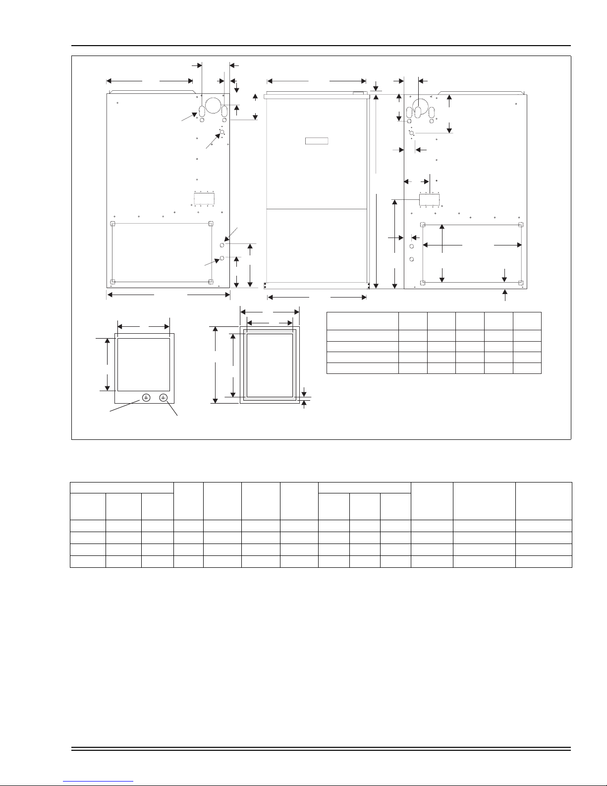
MODELS
P*XU -V & G9V-UH
60 / 55 / 1200 /”B”
80 / 75 / 1600 /”C”
100 / 95 / 2000 /”C”
120 / 112 / 2000 /”D”
1. Vent pipe must be increased to 3” on this unit.
3/4”
FLANGE
6
1-3/4
A
17-1/2
21
21
24-1/2
1-3/4
14-1/2
16-1/4
19-3/4
19-3/4
23-1/4
8-7/8
22-3/4
B
CDE
13-1/8
16-5/8
16-5/8
20-1/8
3/4
2
2
2
2
2
2
3
1
2
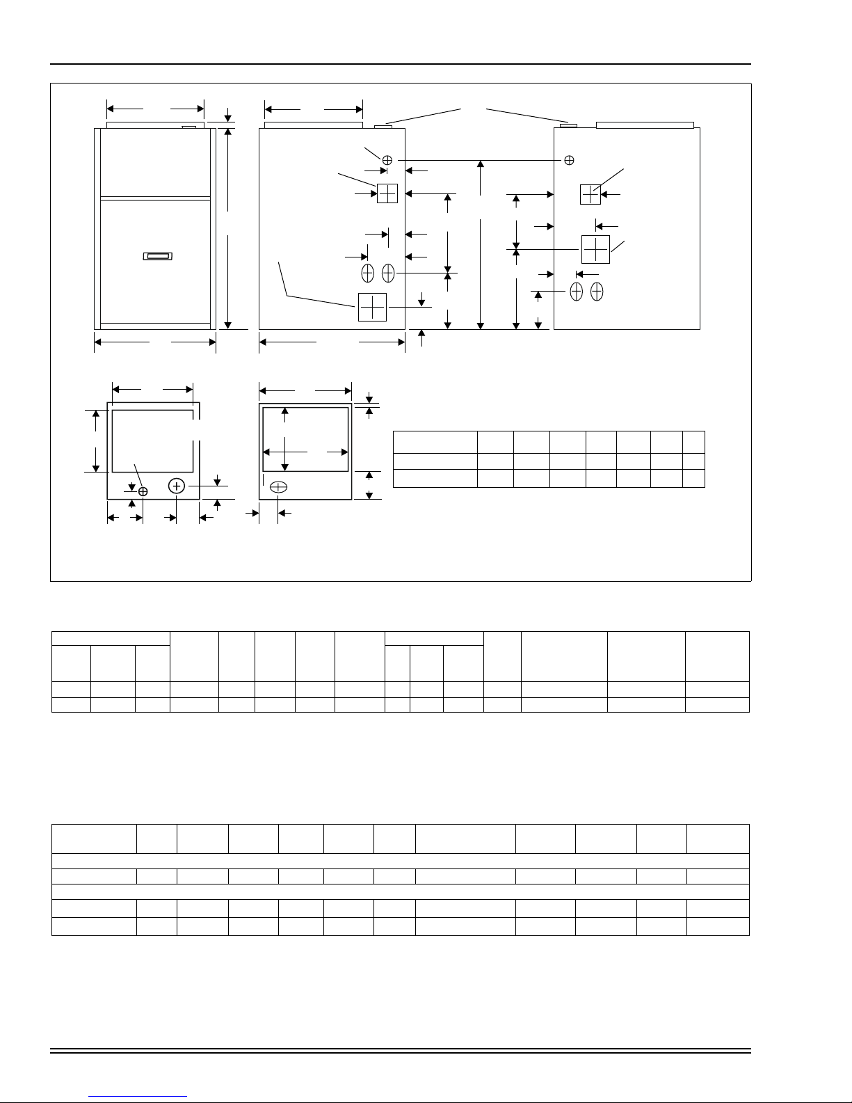
FIGURE 1 : Dimensions - Upflow models
Table 1 : RATINGS & PHYSICAL / ELECTRICAL DATA - UPFLOW MODELS
P*XU-V/G9V—UH
INPU
OUTPUT
MBH
H/L
MBH
H/L
NOM.
CFM
AFUE
1
LOW
FIRE
TEMP.
RISE °F
HIGH
FIRE
TEMP.
RISE °F
MAX.
OUTLET
AIR
TEMP. °F
60/39 55/36 1200 93.5 45 - 75 45 - 75 175 1/2 1.7 11x8 9.6 20 14
80/52 75/48 1600 93.5 30 - 60 30 - 60 165 3/4 3.6 11x8 12.0 20 14
100/65 95/60 2000 94.0 30 - 60 30 - 60 160 1 4.3 11x10 14.5 20 12
120/78 112/72 2000 94.0 45 - 75 45 - 75 175 1 4.4 11x10 14.5 20 12
1.
AFUE numbers are determined in accordance with DOE test procedures
2.
Wire size and overcurrent protection must comply with the National Electrical Code (NFPA-70-latest edition).
For altitudes above 2,000 ft., reduce capacity 4% for each 1,000 ft. above sea level. Refer to instructions 035-14460-000.
·
Wire size based on copper conductors, 60°C, 3% voltage drop.
·
Continuous return air temperature must not be below 55°F.
·
BLOWER
HP AMPS SIZE
TOTAL
UNIT
AMPS
MAX.
OVER-CURRENT
PROTECT
2
MIN WIRE SIZE
(AWG) @ 75 FT.
ONE WAY
2
Unitary Products Group 5
Page 6
035-17468-001 Rev. A (801)
20
1-7/8
B
20
3/4
T'STAT WIRING
7/8 K.O.
45
CONDENSATE
DRAIN ACCESS
3-1/4 x 3
AIR INTAKE
3-5/8 x 3-5/8
( CONN. SIZE/
G
PIPE SIZE)
GAS INLET
1-1/4 x 2-1/2
5-1/4
1-1/4
3-3/4
1-3/4
2-3/4
A
FRONT RIGHT SIDE
B
28-1/2
LEFT SIDE
A
D
VENT CONNECTION
35
18-1/2
16-3/4
7-1/2
6-1/4
4-1/8
3-3/4
1-1/4
ALT. GAS INLET
1-1/4 x 2-1/2
1-3/8
VENT CONNECTION
POWER
WIRING
7/8 K.O.
E F
TOP IMAGE
RETURN END
(VENT SIZE
5-3/8
19-1/4
C
H
FRONTFRONT
BOTTOM IMAGE
RETURN END
P*XD-V / G9V-DH
80/75/1200/B
120/112/2000/D
8
MODELS
ABCDEFG
17-1/2
16-1/4
24-1/2
23-1/4
14-3/4
21-3/4
2
2 (3)
1. VENT PIPE MUST BE INCREASED TO 3" ON THIS MODEL.
ALL DIMENSION ARE IN INCHES, AND ARE APPROXIMATE.
CONDENSATE
DRAIN ACCESS
3-1/4 x 3
AIR INTAKE
3-5/8 x 3-5/8
( CONN. SIZE/
G
PIPE SIZE)
6-5/8
1
10-1/8
2-1/4
2-1/423
FIGURE 2 : Dimensions - Downflow/Horizontal Models
Table 2 : RATINGS & PHYSICAL / ELECTRICAL DATA - DOWNFLOW/HORIZONTAL MODELS
P*XD-V/G9V-DH
INPU
OUTPUT
MBH
H/L
MBH
H/L
NOM.
CFM
CABINET
WIDTH
(INCHES)
AFUE
1
TEMP.
RISE °F
LOW
FIRE
HIGH
FIRE
TEMP.
RISE °F
MAX.
OUTLET
AIR
TEMP. °F
80/52 75/48 1200 17-1/2 92.0 35-65 35-65 165 1/2 1.7 11 x 8 12.0 20 14 128
120/78 112/72 2000 24-1/2 92.0 40-70 40-70 170 1 4.4 11 x 10 14.5 20 12 184
1.
AFUE numbers are determined in accordance with DOE test procedures
2.
Wire size and overcurrent protection must comply with the National Electrical Code (NFPA-70-latest edition).
•
For altitudes above 2,000 ft., reduce capacity 4% for each 1,000 ft. above sea level. Refer to Form 035-14460-000.
•
Wire size based on copper conductors, 60°C, 3% voltage drop.
•
Continuous return air temperature must not be below 55°F.
BLOWER
HP AMPS SIZE
TOTAL
UNIT
AMPS
MAX.
OVER-CURRENT
PROTECT
2
MIN WIRE SIZE
(AWG) @ 75 FT.
ONE WAY
2
OPERATING
WT. (LBS)
Table 3 : UNIT CLEARANCES TO COMBUSTIBLES
APPLICATION TOP FRONT REAR
LEFT
SIDE
RIGHT
SIDE
FLUE FLOOR/BOTTOM CLOSET ALCOVE ATTIC
UPFLOW MODELS (P*XU-V / G9V-UP)
UPFLOW 1 3 0 0 0 0 COMBUSTIBLE YES YES YES NO
DOWNFLOW / HORIZONTAL MODELS (P*XD-V / G9V-DH)
DOWNFLOW 1 3 0 0 0 0
HORIZONTAL 1 3 0 0
1.
Special floor base or air conditioning coil required for use on combustible floor.
2.
Minimum of 8” clearance required to install condensate removal system.
3.
Line contact only permitted between lines formed by the intersection of the rear panel and side panel (top in horizontal position) of
+
0
COMBUSTIBLE
0
COMBUSTIBLE
1
YES YES YES NO
2
NO YES YES
the furnace jacket and building joists, studs or framing.
LINE
CONTACT
YES
3
6 Unitary Products Group
Page 7
035-17468-001 Rev. A (801)
DUCTWORK
The duct system's design and installation must:
1. Handle an air volume appropriate for the served space
and within the operating parameters of the furnace
specifications.
2. Be installed in accordance with standards of NFPA
(National Fire Protection Association) as outlined in
NFPA pamphlets 90A and 90B (latest editions) or applicable national, provincial, local fire and safety codes.
3. Create a closed duct system. The supply duct system
must be connected to the furnace outlet and the return
duct system must be connected to the furnace inlet. Both
supply and return duct systems must terminate outside
the space containing the furnace.
4. Complete a path for heated or cooled air to circulate
through the air conditioning and heating equipment and
to and from the conditioned space.
The cooling coil must be installed in the supply air
duct. Cooled air must not be passed over the heat
exchanger.
When the furnace is used in conjunction with a cooling coil,
the coil must be installed parallel with, or in the supply air side
of the furnace to avoid condensation in the primary heat
exchanger.
When a parallel flow arrangement is used, the dampers or
other means used to control air flow must be adequate to prevent chilled air from entering the furnace, and if manually
operated, must be equipped with means to prevent operating
of either unit unless the damper is in the full heat or cool
position.
UPFLOW MODELS
SUPPLY PLENUM CONNECTION
Attach the supply plenum to the furnace outlet duct connection flanges.
This is typically through the use of S
cleat material when a metal plenum is
used. The use of an approved flexible
duct connector is recommended on all
installations. This connection should be
sealed to prevent air leakage.
If a matching cooling coil is used, it
may be placed directly on the furnace
outlet and sealed to prevent leakage.
Follow the coil instructions for installing
the supply plenum.
On all installations without a coil, a removable access panel
is recommended in the outlet duct such that smoke or
reflected light would be observable inside the casing to indicate the presence of leaks in the heat exchanger. This
access cover shall be attached in such a manner as to prevent leaks.
RETURN DUCT CONNECTION
Return air may enter the furnace through the side(s) or bottom depending on the type of application. Return air may
not be connected into the rear panel of the unit. Refer to
the "Filter Installation" section of this instruction for the type of
application desired for specific installation details.
NOTE: In order to achieve the airflow indicated in the table, it
is recommended those applications over 1800 CFM use
return air from two sides, one side and the bottom or bottom
only. For single return application, see data and notes on
blower performance data tables in this manual.
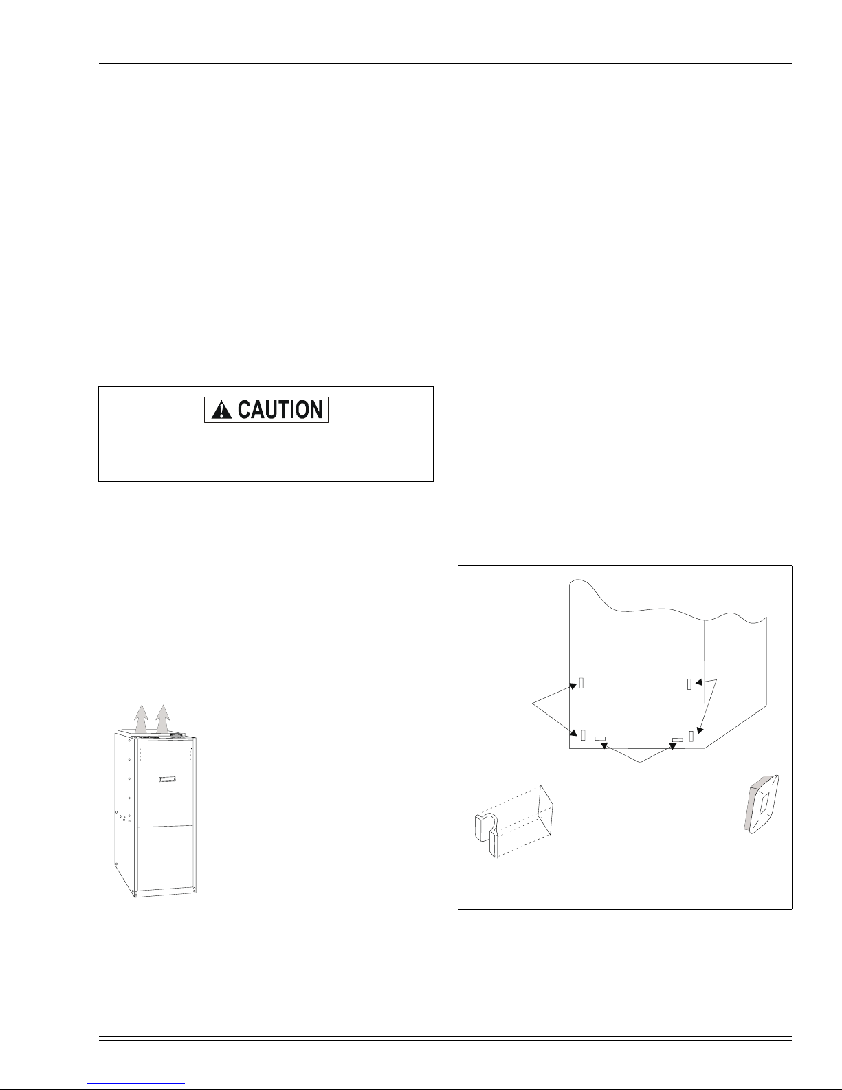
UPFLOW FILTER INSTALLATION
All applications require the use of a filter. A high velocity filter
and retainer are provided for field installation.
Internal Installation
1. Select desired filter position (left/right side, and/or bottom). Remove the corresponding cabinet cut-outs per
instructions provided.
2. Install snap-in retainer clips into the corresponding slots
from the outside rear of the cabinet (Refer to Figure 3.)
To prevent cabinet air leaks, install snap-in plugs (provided) into the unused slots at the outside rear of the
cabinet.
3. Install the wire retainer inside the cabinet. Insert the
open ends of the wire retainer into the clip loops at the
rear of the blower compartment. The retainer wire should
pivot freely like a hinge, on the clips at the rear of the
cabinet. See Figure 4.
FURNACE
(REAR CABINET)
RIGHT
SIDE
SLOTS
BOTTOM SLOTS
CABINET
SLOT
FILTER SUPPORT
CLIPS (PROVIDED)
LEFT
SIDE
SLOTS
PLUG UNUSED
CABINET SLOTS
WITH PLUGS
(PROVIDED)
FIGURE 3 : Furnace Filter Slot Locations
Unitary Products Group 7
Page 8
POSITION WIRE RETAINER
PROVIDED UNDER FLANGE
035-17468-001 Rev. A (801)
NOTE: Some accessories such as electronic air cleaners and
pleated media may require a larger side opening. Follow the
instructions supplied with the accessory for side opening
requirements.
FILTER
CLIPS
RIGHT SIDE
INSTALLATION
SHOWN
PROVIDED
FURNACE
FRONT
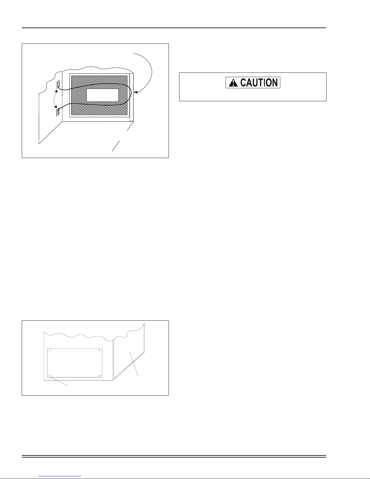
FIGURE 4 : Side Filter Retainer Placement
4. Install the filter(s) provided. Cut filter if necessary to
match air opening in cabinet. Filter should extend
beyond opening edge as much as possible to prevent air
from bypassing the filter. DO NOT remove stiffening rods
from inside the filter. Shorten the rods, if necessary, to
match final filter size.
5. Position the filter between the wire retainer and the cabinet wall (or floor) so it completely covers the cabinet air
opening and secure the filter in place at the front of the
cabinet by fastening the closed (looped) end of the
retainer wire under the flanged edge of the cabinet.
When properly installed the filter should fit flush with all
four sides of the cabinet wall.
NOTE: Air velocity through throw-away type filters may not
exceed 300 feet per minute. All velocities over this require the
use of high velocity filters.
Side Return - External Filter
Locate and knock out the square corner locators. These indicate the size of the cutout to be made in the furnace side
panel, See Figure 5.
FRONT OF
CORNER
MARKINGS
FURNACE
FIGURE 5 : Side Return Cutout Markings
Install the side filter rack following the instructions provided
with that accessory. If a filter(s) is provided at another location in the return air system, the ductwork may be directly
attached to the furnace side panel.
All installations must have a filter installed.
The return duct may be attached to the furnace by S-cleat,
bend tabs or other approved methods. Be sure to seal the
duct to the furnace to prevent air leakage.
Where the return duct system is not complete, the return connection must run full size to a location outside the utility room
or basement. For further details, consult Section 5.3 (Air for
Combustion and Ventilation) of the National Fuel Gas Code,
ANSI Z223.1, or CAN/CGA B149.1 or.2, Installation Code latest editions.
Bottom Return
Bottom return applications normally pull return air through a
base platform or return air plenum. Be sure the return platform structure is suitable to support the weight of the furnace.
Be sure to seal the furnace to plenum connection to prevent
air leakage.
The bottom panel is equipped with a perforated opening for
easy removal. Tabs must be cut with sheet metal snips to
allow removing knock-out. Scribe marks are included for
forming flanges for attachment of the return air ductwork.
NOTE: If an external mounted filter rack is being used, see
the instructions provided with that accessory for proper hole
cut size.
Upflow attic installations must meet all minimum clearances
to combustibles and have floor support with required service
accessibility.
DOWNFLOW/HORIZONTAL MODELS
COOLING COIL TRANSITION
These furnace models are equipped with perforations in the
supply air wrapper flanges that allow for easy application of
air conditioning coil to the furnace without the use of sheet
metal transition pieces, These perforations can be bent in
either direction depending on the type of application - either
downflow or horizontal left and right. Refer to either the
“Downflow Application” or “Horizontal Application” section
below for specific instructions on how to install the coil.
Downflow Installations
For installation of air conditioning coil in a downflow application, the perforations in the wrapper flanges must be bent in
towards the heat exchanger to allow for the coil duct flange to
recess into the furnace. Refer to the installation instructions
supplied with the air conditioning coil for additional information and completion of the coil installation.
NOTE: Duct pliers or other suitable tool can be used to bend
perforations. To help bend flanges in a straight line, scribe a
line between the perforations prior to bending.
8 Unitary Products Group
Page 9
035-17468-001 Rev. A (801)
Horizontal Installations
For installation of an air conditioning coil in a horizontal application, the perforations in the wrapper flanges must be bent
away from the heat exchanger to create duct flanges so the
air conditioning coil can be properly seated on the furnace.
Refer to the installation instructions supplied with the air conditioning coil for additional information and completion of the
coil installation.
NOTE: Duct pliers or other suitable tool can be used to bend
perforations. To help bend flanges in a straight line, scribe a
line between the perforations prior to bending.
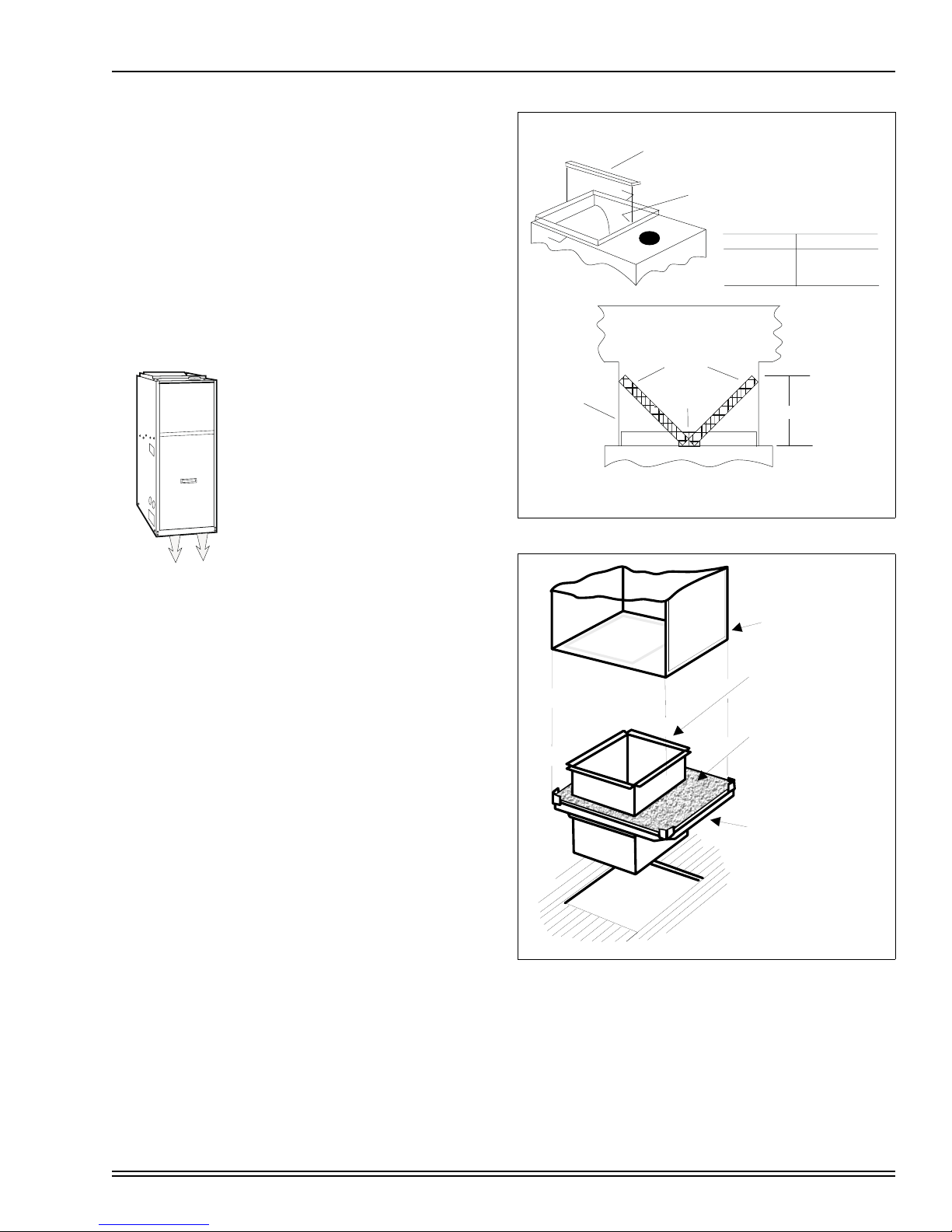
DOWNFLOW APPLICATION
DOWNFLOW FILTERS
A top return filter rack is supplied with
the furnace. Two 14" x 20" permanent
washable filters are supplied with each
unit.
Downflow furnaces typically are
installed with the filters located above
the furnace, extending into the return
air duct. See Figure 6.
Any branch duct must attach to the vertical ductwork above the filter height
(FH).
The filter rack (provided) should be secured to the center of
the front and rear flanges at the furnace top. Drill a hole
through the front and rear duct flange into the filter rack and
secure it with a sheet metal screw.
Refer to the unit rating plate for furnace model then see the
dimensions page of this instruction for return air plenum
dimensions. Install the plenum following instructions under
Ductwork in this instruction
SUPPLY AIR DUCTS
Installations on combustible material or floors must use a
combustible floor base (shown in Figure 7 - 1CB0317 or
1CB0324) as specified on the rating plate or a matching cooling coil. Follow the instructions supplied with the combustible
floor base accessory.
This base can be replaced with a matching cooling coil, properly sealed to prevent leaks. Follow the cooling coil instructions for installing the plenum.
All downflow application supply duct systems must be
designed and installed in accordance with the standards of
NFPA 90A and 90B, and/or all local codes.
FILTER RACK
(FACTORY SUPPLIED)
A
DUCTWORK
A
NOTE: FILTER ACCESS THRU DUCTWORK MUST BE PROVIDED FOR
REMOVALAND CLEANING
CROSS SECTION A-A
(WITH PLENUM AND FILTERS)
RACK AND FILTERS SECURED
INSIDE BLOWER SECTION
FOR SHIPMENT
CASING SIZE DIMENSION FH
16-1/4 12-3/4
22-1/4 11
26-1/4 8-1/4
FILTERS
FILTER
RACK
FIGURE 6 : DOWNFLOW FILTERS
COMBUSTIBLE FLOOR
BASE ACCE
BRANCH
DUCTS
FH
DOWNFLOW
FURNACE
ARM AIR PLENUM
W
ITH 1" FLANGES
W
FIBERGLASS
INSULATION
FIBERGLASS TAPE
UNDER FLANGE
SSORY
Unitary Products Group 9
FIGURE 7 : Combustible Floor Base Accessory
Page 10
DOWNFLOW / HORIZONTAL MODELS HORIZONTAL APPLICATION
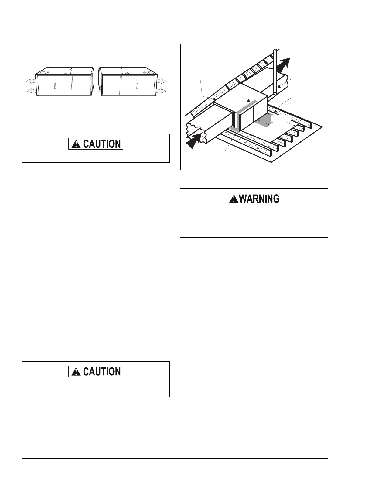
Downflow furnaces may be installed horizontally with the supply airflow toward the left or right by laying the unit on the left
or right side panel.
LINE CONTACT ONLY PERMISSIBLE
BETWEEN LINES FORMED BY THE
INTERSECTION OF FURNACE TOP
AND TWO SIDES AND BUILDING
JOISTS, STUDS OR FRAMING
GAS PIPING
035-17468-001 Rev. A (801)
SUPPLY AIR
VENT (Maintain
required clearances
to combustibles)
SHEET METAL
IN FRONT OF
FURNACE
COMBUSTION AIR
OPENINGS IS
RECOMMENDED
12”
30” MIN.
WORK AREA
Do not install the unit on the rear panel.
After determining the best orientation, lay the unit on top of
the shipping carton to protect the finish. The appropriate electrical knock-outs for power wiring, control wiring and gas piping should be removed at this time.
For horizontal application, return air may enter through the
bottom, left side or right side panel or any combination of
these openings. Return air may not be connected into the
rear panel of the unit.
HORIZONTAL FILTERS
All filters and mounting provision must be field supplied. Filter(s) may be located in the duct system external to the furnace or in a return filter grille(s). Refer to furnace accessories
on Page 30 for External Filter Kit options.
ATTIC INSTALLATION
This appliance is design certified for line contact for furnaces
installed horizontally. The intersection of the furnace top and
sides form a line. This line may be in contact with combustible
material. Refer to Figure 8.
Secure a platform constructed of plywood or other building
material to the floor joists. Sheet metal, 12" in front of the furnace combustion air openings is recommended. (Refer to
Figure 8).
NOTE: The unit must be elevated to allow clearance to the
condensate trap and drain pipe. A minimum of 8” clearance is
required for this purpose.
RETURN AIR
SEDIMENT
TRAP
FIGURE 8 : Typical Attic Installation
When a furnace is installed in an attic or other insulated space, keep all insulating materials at least 12"
away from furnace and burner combustion air openings.
NOTE: See crawl space installation for suspending the furnace in attic installations.
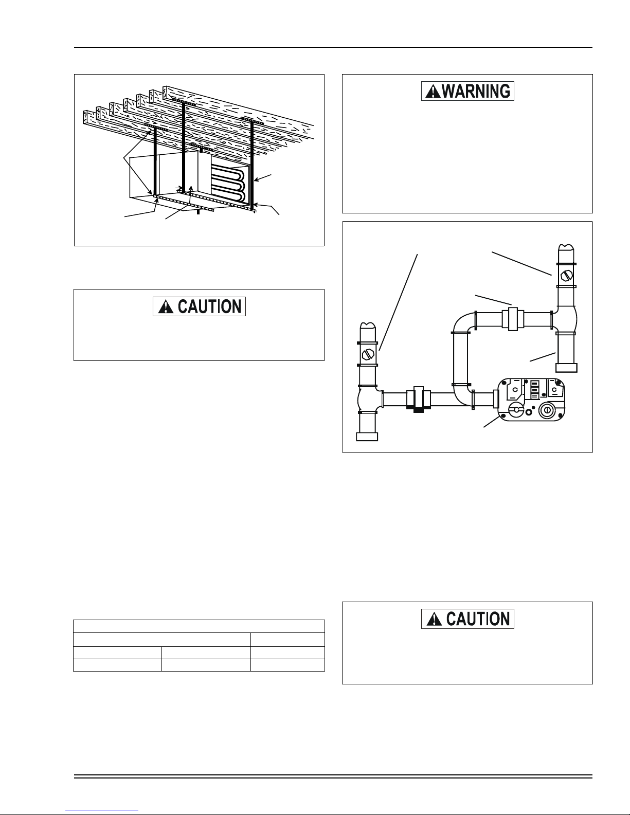
CRAWL SPACE INSTALLATION
The furnace can be hung from floor hoists or installed on suitable blocks or pad. Blocks or pad installations shall provide
adequate height to ensure the unit will not be subject to water
damage.
When suspending the furnace from rafters or floor joists using
rod, pipe or straps, refer to Physical Data and,Table 3, “UNIT
CLEARANCES TO COMBUSTIBLES,” on Page 6, for furnace weights to determine suitable means of suspension.
Angle supports should be placed at the supply air end and
near the blower deck. (Refer to Figure 9.) Do not support at
return air end of unit.
Units may also be suspended by using straps or other material at the same location. All four suspension points must be
level to ensure quiet furnace operation
If this furnace is installed over a finished space, a
condensate safety pan must be installed.
10 Unitary Products Group
Page 11
035-17468-001 Rev. A (801)
ANGLE IRON
BRACKET
1” MAX. BETWEEN
ROD & FURNACE
6” MIN BETWEEN
ROD & FURNACE
1” MAX. BETWEEN
ROD & FURNACE
FIGURE 9 : Typical Furnace Installation Using
Suspension Materials
In any application where temperatures below freezing are possible, See “BELOW FREEZING LOCATIONS” on page 4.
GAS PIPING
SUPPORT
ROD
An overpressure protection device, such as a pressure regulator, which conforms to the National Fuel
Gas Code, ANSI Z223.1 (U.S.) or CAN-B149.1 or .2
(Canada) and acts to limit the downstream pressure
to a value that does not exceed 0.5 PSI (14” w.c.),
must be installed in the gas piping system upstream
of the furnace. Failure to do so may result in a fire or
explosion or cause damage to the furnace or some
of its components.
EXTERNAL MANUAL
SHUTOFF VALVE
GROUND JOINT UNION
MAY BE INSTALLED
INSIDE OR OUTSIDE UNIT
TO GAS
SUPPLY
DROP LEG
TO GAS
SUPPLY
The gas supply should be a separate line and must be
installed in accordance with the National Fuel Gas Code,
ANSI Z223.1 (latest edition), or the CAN/CGA B149.1 or .2
Installation Codes (latest edition) and all applicable local and
utility requirements.
Some utility companies or local codes require pipe sizes
larger than the minimum sizes listed in these instructions and
in the codes. Properly sized wrought iron, approved flexible
or steel pipe must be used when making gas connections to
the unit. The installation of a drop leg and ground union is
required (Refer to Figure 10).
Gas piping may be connected from either side of the furnace
using any of the gas pipe entry knockouts on both sides of
the furnace (Refer to Figure 1 for locations and dimensions).
NOTE: Plan your combustion air piping before determining
the correct gas pipe entry. Use 90 degree service elbow(s), or
short nipples and conventional 90 degree elbow(s) to enter
through the cabinet access holes.
INLET GAS PRESSURE RANGE
NATURAL GAS PROPANE (LP)
Minimum 4.5 In. W.C. 11 In. W.C.
Maximum 13.8 In. W.C. 13.8 In. W.C.
NOTE: An accessible manual shutoff valve must be installed
upstream of the furnace gas controls and within 6 feet of the
furnace.
GAS VALVE
FIGURE 10 : Gas Piping
NOTE: A 1/8” NPT plug is included in the inlet side of the gas
valve for measuring incoming gas pressure.
The furnace must be isolated from the gas supply piping system by closing its individual external manual shutoff valve
during any pressure testing of the gas supply piping system
at pressures equal to or less than 1/2 psig (3.48 kpa).
The furnace and its individual shutoff valve must be disconnected from the gas supply piping system during any pressure testing of that system at test pressures in excess of 1/2
psig (3.48 kpa).
Never apply a pipe wrench to the body of the combination automatic gas valve. A wrench must be
placed on the projection or wrench boss of the valve
when installing piping to it.
Unitary Products Group 11
Page 12
Compounds used on threaded joints of gas piping
must be resistant to the action of liquefied petroleum
LP gases. After connections are made, leak-test all
pipe connections.
After all gas piping connections are completed, leak
test all joints, fittings and furnace connections with
rich soap and water solution, commercially available
bubble type leak detection fluid, or other approved
means.
Do not use an open flame or other source of
ignition for leak testing.
ELECTRICAL POWER CONNECTION
Field wiring to the unit must conform to and be grounded in
accordance with the provisions of the National Electrical
Code ANSI/NFPA No. 70-latest edition, Canadian Electric
Code C22.1 Part 1 - (latest edition) and/or local codes. Electric wires which are field installed shall conform with the temperature limitation for 63°F / 35°C rise wire when installed in
accordance with instructions. Specific electrical data is given
for the furnace on its rating plate and in Table 1 on Page 5 or
Table 2 on Page 6.
Provide a power supply separate from all other circuits. Install
overcurrent protection and disconnect switch per local/
national electrical codes. The switch should be close to the
unit for convenience in servicing. With the disconnect switch
in the OFF position, check all wiring against the unit wiring
label. Also, see the wiring diagrams in this instruction.
NOTE: The furnace’s control system depends on correct
polarity of the power supply and a proper ground connection.
Refer to FURNACE CONTROL DIAGNOSTICS on Page 37,
for symptoms of reversed power supply polarity.
Use copper conductors only.
Connect the power supply as shown on the unit wiring label
on the inside of the blower compartment door and Figure 11
or 12 on Page 12. The black furnace lead must be connected
to the L1 (hot) wire from the power supply. The white furnace
lead must be connected to neutral. Also, the green equipment ground wire must be connected to the power supply
ground.
Remove the screws retaining the wiring box cover. Route the
power wiring through the opening in the unit into the junction
box with a conduit connector or other proper connection.
Make wiring connections referring to Figure 11 or 12 and
replace the junction box cover and screws.
035-17468-001 Rev. A (801)
GND.
N
L1
(HOT)
WHT
GRN
BLK
JUNCTION BOX
DOOR SWITCH
CLASS 2 SYSTEM
CONTROL WIRING
TO THERMOSTAT
IGNITION MODULE
HUM (HOT)
EAC (HOT)
CFM/TIMER
BOARD
BLK/BLK
WHT/WHT
GRN/GRN
HUM
EAC
WIRING INSIDE
JUNCTION BOX
BURNER
COMPARTMENT
BLOWER
COMPARTMENT
FIGURE 11 : Electrical Wiring - Upflow Models
JUNCTION
BOX
BLOWER COMPARTMENT
IGNITION MODULE
TRANSFORMER
DOOR
SWITCH
BURNER COMPARTMENT
L1
(HOT)
BLK
N
WHT
HUM (HOT)
GND
GRN
EAC (HOT)
WIRING INSIDE
JUNCTION BOX
VENT PIPE
CLASS 2 SYSTEM
CONTROL WIRING
TO THERMOSTAT
BLK/BLK
WHT/WHT
GRN/GRN
FLUE
CHASE
FIGURE 12 : Electrical Wiring - Downflow / Horizontal
Models
An alternate wiring method is to use a field provided 2 x 4 box
and cover on the outside of the furnace. Route the furnace
leads into the box using a protective bushing where the wires
pass through the furnace panel.
12 Unitary Products Group
Page 13

035-17468-001 Rev. A (801)
NOTE: The power connection leads and wiring box on upflow
units may be relocated to the left side of the furnace. Remove
the screws and cut wire tie holding excess wiring. Reposition
on the left side of the furnace and fasten using holes provided.
BLK
WHT
GRN
BLK (HOT)
WHT (NEUTRAL)
GRD
NOMINAL
120 VOLT
ELECTRICAL CONTROL CONNECTIONS
Install the field-supplied thermostat. The thermostat instructions for wiring are packed with the thermostat. With the thermostat set in the OFF position and the main electrical source
disconnected, complete the low-voltage wiring from the thermostat to the terminal strip on the cfm timer board. Connect
Class 2 control wiring for single stage thermostat (refer to
(Refer to Figure 13 on Page 13)) or for two stage thermostat
(refer to (Refer to Figure 14 on Page 13).
Set the heat anticipator in the room thermostat as shown below.
Setting it lower will cause short cycles. Setting it higher will cause
NOTE: Some electronic thermostats do not have adjustable
heat anticipators. They may have other type cycle rate adjustments. Follow the thermostat manufacturer's
instructions.
FIGURE 13 : Field Wiring for Single Stage Thermostat
the room temperature to exceed the setpoint.
Two-Stage Thermostat
First Stage .4 Amps
Second Stage .1 Amps
Single Stage Thermostat .4 Amps
TYPICAL FIELD WIRING - SINGLE STAGE
HUMY2
SINGLE STAGE
THERMOSTAT
Y1
R
W1
G
C
HUM
Y1
Y
RW1W2G
C
OX/L
10
15
20
MINUTE SELECT
CFM/TIMER BOARD
HEATPUMP
COOL HEAT DELAY ADJ
HUMDISTAT
HUM
Y2
Y1
Y
R
W1W2
O
C
O
X/L
TIME OFF
10
15
20
MINUTE SELECT
LOW HEAT TIME
ADJUSTMENT
P9
P6
W1
W2
TYPICAL FIELD WIRING - TWO STAGE
TWO STAGE
THERMOSTAT
Y2
Y1
R
W1
W2
G
C
X/L
CFM/TIMER
BOARD
HUM
Y2
Y1
Y
RW1W2
G
COX/L
OUTDOOR
UNIT
Y2
Y1
Y2 OUT
R
C
X/L
JUMPER MUST BE IN
TIMER OFF POSITION
FIGURE 14 : Field Wiring for Two Stage Thermostat
The 24-volt, 40 VA transformer is sized for the furnace components only, and should not be connected to power auxiliary
devices such as humidifiers, air cleaners, etc. The transformer
may provide power for an air conditioning unit contactor.
NOTE: Apply strain relief to thermostat lines passing through
cabinet.
ACCESSORY CONNECTIONS
Do not exceed 1.0 amp loading.
The furnace control will allow power switching control of various accessories. Refer to Figure 15 for connection details.
ELECTRONIC AIR CLEANER CONNECTION
The junction box contains a clearly marked wire for connection to an electronic air cleaner. This wire provides 120 VAC
(1.0 amp maximum) during circulating blower operation.
HUMIDIFIER CONNECTION
The junction box contains a clearly marked wire for connection to a humidifier. This wire provides 120 VAC (1.0 amp
maximum) during heat speed operation of the circulating
blower
HUM. HOT
EAC HOT
BLK
WHT
BLK
WHT
EAC
HUM
EAC
HUM
SWITCHED
CIRCUITS
NEUTRALS
115 VOLT
HUMIDIFIER
115 VOLT
ELECTRONIC
AIR CLEANER
Unitary Products Group 13
FIGURE 15 : Accessory Connections
Page 14

COMBUSTION AIR AND VENT SYSTEM
T
035-17468-001 Rev. A (801)
This furnace is certified to be installed with one of
three possible intake/vent configurations.
1. Two-pipe with a sealed combustion intake/vent system
using outdoor combustion air.
2. Single pipe vent system using combustion air from the
area surrounding the furnace.
3. Two-pipe intake/vent system using combustion air from a
ventilated attic space and a vent pipe to the outside.
Be sure to follow the appropriate venting section details,
related information and limitations for your type of installation.
Furnace Intake / Vent Connection Size (All Models)
60 - 100 MBH 120 MBH
Intake 2” 3"
Vent 2”
1.
Vent must be increased to 3" on this model.
Note 1:Any vent pipe size change must be made outside
furnace casing in a vertical pipe section to allow proper
drainage of condensate.
Note 2: An offset using two 45 degree elbows will be required
for plenum clearance when the vent is increased to 3”.
1
2"
METHOD ONE: TWO PIPE SEALED
COMBUSTION AIR & VENT SYSTEM
COMBUSTION AIR INTAKE/VENT CONNECTIONS
This type installation requires outdoor combustion air. Two
separate, properly-sized pipes must be used. One bringing
air from the outdoors to the furnace combustion air intake collar on the burner box, and a second pipe from the furnace
vent connection (top right of unit) back to the outdoors. Refer
to Figure 16 or 17.
The intake/vent should be located either through the wall
(horizontal or side vent) or through the roof (vertical vent).
Care should be taken to locate side vented systems where
trees or shrubs will not block or restrict supply air from entering or combustion products from leaving the terminal.
Also, the terminal assembly should be located as far as possible from a swimming pool or a location where swimming
pool chemicals might be stored. Be sure the terminal assembly follows the outdoor clearances listed in Table 3 for U.S.
installations: In Canada, refer to CAN/CGA-B149.1 or .2
Installation Code (latest edition-Venting Systems and Air
Supply).
COMBUSTION AIR
PIPE PASSES
THROUGH TOP PANEL
CONNECTS TO
COLLAR ON TOP
OF BURNER BOX
VENT PIPE
CEMENTS
INTO SOCKE
JUST UNDER
TOP PANEL
FIGURE 16 : Air Intake and Vent Locations - Upflow
VENT PIPE PASSES
THROUGH TOP PANEL
OPTIONAL
LEFT SIDE
COMBUSTION
AIR PIPE
ROUTING
COMBUSTION
AIR PIPE
CONNECTS TO
COLLAR ON
BOTTOM OF
BURNER BOX
FIGURE 17 : Air Intake and Vent Locations -
Downflow/Horizontal
COMBUSTION AIR/VENT PIPE SIZING
To select the proper size piping for combustion air intake and
venting refer to Table 6 on Page 19. The size will be determined by a combination of furnace model, total length of run,
and the number of elbows required. The following rules must
also be observed.
14 Unitary Products Group
Page 15

035-17468-001 Rev. A (801)
Table 4 : INTAKE/VENT PIPING - 2 PIPE SYSTEM
Upflow
Models
60 / 55 / 1200 / B
100 / 95 / 2000 / C
60 / 55 / 1200 / B
100 / 95 / 2000 / C
120 / 112 / 2000 / D 3” Only 6 5 4 N/A
1.
Elbow count does not include the elbows required for
the termination. See Step 4 under Combustion Air/Vent
Pipe Sizing
Pipe
Size
Max. Elbows vs. One Way Vent
Length (Ft.)
5 - 40 45 50 75
2”654N/A80 / 75 / 1600 / C
3”876580 / 75 / 1600 / C
1
Tabl e 5 : INTAKE/VENT PIPING - 2 PIPE SYSTEM
Downflow/Horizontal
Models
80 / 75 / 1200 / B 2” 6 5 4 N/A
80 / 75 / 1200 / B 3” 8765
120 / 112 / 2000 / D 3” Only 6 5 4 N/A
1.
Elbow count does not include the elbows required for
the termination. See Step 4 under Combustion Air/Vent
Pipe Sizing
Pipe
Size
Max. Elbows vs. One Way Vent
Length (Ft.)
5 - 30 35 40 60
1
NOTE: If installing furnace at altitudes between 2000 - 4500
ft., the maximum allowable intake and vent pipe length must
be reduced by 10 ft. If the installation requires the maximum
allowable intake and vent pipe length, the furnace must be
converted for high altitude operation. Refer to the proper high
altitude application instruction for details.
1. Long radius elbows are required for all units.
2. Elbows are assumed to be 90 degrees. Two 45 degree
elbows count as one 90 degree elbow.
3. Elbow count refers to combustion air piping and vent piping separately. For example, if the table allows for 5
elbows, this will allow a maximum of 5 elbows in the
combustion air piping and a maximum of 5 elbows in the
vent piping.
Three vent terminal elbows (two for vent pipe and one for
4.
air intake pipe) are already accounted for and should not
be counted in the allowable total indicated in the table.
See section on vent terminal. These parts are shown
shaded.
5. Combustion air and vent piping must be of the same
diameter.
6. All combustion air/vent pipe and fittings must conform to
American National Standards Institute (ANSI) standards
and American Society for Testing and Materials (ASTM)
standards D1785 (Schedule 40 PVC), D2665 (PVCDWV), F891 (PVC-DWV Cellular Core). D2241 (SDR-21
and SDR-26 PVC), D2261 (ABS-DWV), or F628 (Schedule 40 ABS. Pipe cement and primer must conform to
ASTM Standards D2564 (PVC) or D2235 (ABS).
7. The use of flexible connectors or no hub connectors in
the vent system is not allowed. This type connection is
allowed in the combustion air pipe near the furnace for
air conditioning coil accessibility.
VENT TERMINATION (2-PIPE)
Side wall horizontal vent terminals and roof mounted vertical
terminals may be field fabricated. Standard PVC/SRD fittings
may be used. Terminal configuration must comply as detailed
in this section.
NOTE: Combustion air and vent pipes must terminate
together in the same atmospheric zone, either through a roof
or sidewall.
NOTE: Accessory concentric intake/vent terminations,
models 1CT0302 and 1CT0303 are available and
approved for use with these furnaces. Refer to instructions
035-14287-000 for installation details.
When selecting the location for combustion air/vent termination the following should be considered:
1. Comply with all clearance requirements as listed below.
2. Termination should be positioned where vent vapors will
not damage plants or shrubs or air conditioning equipment.
3. Termination should be located where it will not be
affected by wind gusts, light snow, airborne leaves or
allow recirculation of flue gases.
4. Termination should be located where it will not be damaged or exposed to flying stones, balls, etc.
5. Termination should be positioned where vent vapors are
not objectionable.
VENT CLEARANCES (2-PIPE) U.S. ONLY
Dryer Vent. . . . . . . . . . . . . . . . . . . . . . . . . . . . . . . . . . . 3 ft.
Plumbing Vent Stack. . . . . . . . . . . . . . . . . . . . . . . . . . . 3 ft.
Gas Appliance Vent Terminal . . . . . . . . . . . . . . . . . . . .3 ft.*
From any mechanical fresh air intake. . . . . . . . . . . . . . 1 ft.
From any door, window or non-mechanical fresh air or
combustion air intake . . . . . . . . . . . . . . . . . . . . . . . . . . 1 ft.
Above grade and anticipated snow depth . . . . . . . . . . 1 ft.
Above grade when adjacent to public walkway . . . . . . 7 ft.
From electric, gas meters, regulators and relief equipment -
min. horizontal distance . . . . . . . . . . . . . . . . . . . . . . . . 4 ft.
* Does not apply to multiple installations of this furnace
model. Refer to multi-unit vent terminations.
In Canada, refer to CAN/CGA-B149.1 or .2 Installation
Code (latest edition - Venting Systems and Air Supply)
NOTE: Consideration must be given for degradation of building materials by flue gases.
Unitary Products Group 15
Page 16

035-17468-001 Rev. A (801)
NOTE: Shaded components of the combustion air/vent system shown in the following figures are considered to be part
of the vent terminal. These components should not be
counted when determining piping limitations. Refer to Figure
18 thru Figure 20. Sidewall termination may require sealing or
shielding of building surfaces with a corrosive resistance
material to protect against combustion product corrosion.
OVERHANG
12” MINIMUM
VENT
90°
COMBUSTION AIR
12 SEPARATION BETWEEN
BOTTOM OF COMBUSTION AIR
AND BOTTOM OF VENT
MAINTAIN 12” CLEARANCE ABOVE
HIGHEST ANTICIPATED SNOW LEVEL
OR GRADE WHICHEVER IS GREATER
FIGURE 18 : Horizontal Termination Configuration with 12”
Minimum Clearance
OVERHANG
OVERHANG
12” MINIMUM
VENT
90°
18” MAX.
COMBUSTION AIR
12 SEPARATION BETWEEN
BOTTOM OF COMBUSTION AIR
AND BOTTOM OF VENT
MAINTAIN 12” CLEARANCE ABOVE
HIGHEST ANTICIPATED SNOW LEVEL
OR GRADE WHICHEVER IS GREATER
FIGURE 20 : Horizontal Termination Configuration with
Horizontal Extension
VENTING MULTIPLE UNITS
Each unit must have its own intake/vent piping and termination. Do not use common pipes for combustion air or venting.
The vent terminals must be located as shown in refer to Figure 22 thru Figure 23.
VENT
12” MINIMUM
VENT
90°
COMBUSTION AIR
12 SEPARATION BETWEEN
BOTTOM OF COMBUSTION AIR
AND BOTTOM OF VENT
MAINTAIN 12” CLEARANCE ABOVE
HIGHEST ANTICIPATED SNOW LEVEL
OR GRADE WHICHEVER IS GREATER
FIGURE 19 : Horizontal Termination Raised
Configuration for Additional Clearance
12” VERTICAL SEPARATION
BETWEEN COMBUSTION
AIR AND VENT
VENT
COMBUSTION AIR
MAINTAIN 12” MINIMUM
CLEARANCEABOVE HIGHEST
ANTICIPATED SNOWLEVEL.
MAXIMUM OF 24” ABOVE ROOF.
COMBUSTION AIR
2”
FIGURE 22 : Double Sidewall Termination
6”
FIGURE 23 : Double Rooftop Termination
FIGURE 21 : Vertical Termination
16 Unitary Products Group
Page 17

035-17468-001 Rev. A (801)
PIPING ASSEMBLY
The final assembly procedure for the vent/combustion air piping is as follows:
1. Cut piping to the proper length, beginning at the furnace.
2. Deburr the piping inside and outside.
3. Chamfer the outer edges of the piping.
4. Dry-fit the entire vent/combustion air piping assembly.
5. Disassemble the piping and apply cement primer and
cement per the cement manufacturer's instructions.
Primer and cement must conform to ASTM D2564 for
PVC, or ASTM D2235 for ABS piping.
Solvent cements are flammable and must be used in
well-ventilated areas only. Keep them away from
heat, sparks and open flames (including pilots). Do
not breathe vapors and avoid contact with skin and
eyes.
6. All joints must be made to provide a permanent, air-tight,
water-tight seal.
7. Support the combustion air and vent piping such that it is
angled 1/4” per linear foot so that condensate will flow
back toward the furnace. Piping should be supported
with pipe hangers to prevent sagging. Maximum spacing
between hangers is five (5) feet, except SDR-PVC piping, where maximum spacing is three (3) feet.
8. Seal around the openings where the combustion air and
vent piping pass through the roof of side wall.
For upflow models combustion air is brought into the furnace
through the unit top panel opening. Do not install a pipe into
the intake collar on top of the burner box. Refer to Figure 24.
COMBUSTION AIR
VENT PIPE CEMENTS
INTO SOCKET JUST
UNDER TOP PANEL
FIGURE 24 : Vent Pipe Connection - Upflow
For downflow/horizontal models combustion air is brought
into the furnace through the unit side panel openings.
VENT PIPE PASSES
THROUGH TOP PANEL
Vent piping must be insulated with 1/2” Armaflex
insulation if it will be subjected to freezing
GAS PIPING
KNOCKOUTS
temperatures such as routing through unheated
areas or through an unused chimney.
When combustion air pipe is installed above a
suspended ceiling, the pipe must be insulated with
1/2” Armaflex type insulation. The combustion air
pipe should also be insulated when it passes
through a warm, humid space.
NOTE: Vent pipe must be sloped 1/4” per foot to allow condensate to flow back to the furnace.
FIGURE 25 : Vent Pipe Connection -
COMBUSTION AIR
Downflow/Horizontal
METHOD TWO: ONE PIPE SYSTEM
This type installation will use combustion air from within the
space surrounding the furnace. This may be from within the
space in a non-confined location or it may be brought into the
furnace area from outdoors. It is not directly ducted into the
furnace. A single, properly sized pipe from the furnace vent
connector to the outdoors must be provided.
Unitary Products Group 17
For downflow/horizontal models, remove a minimum of two
gas piping knockouts for combustion air access. Do not
install a pipe into the intake collar on bottom of the burner
box. For details, refer to Figure 25.
Page 18

035-17468-001 Rev. A (801)
COMBUSTION AIR
All installations must comply with Section 5.3, Air for Combustion and Ventilation of the National Fuel Gas Code, ANSI
Z223.1 or Sections 7.2, 7.3 or 7.4 of CAN/CGA B149.1 or .2
Installation Code - latest editions.
An unconfined space is not less than 50 cubic feet per 1000
Btu/hr input rating for all appliances installed in that area.
Rooms communicating directly with the space containing the
appliances are considered part of the unconfined space, if
openings are not furnished with doors.
A confined space is an area with less than 50 cubic feet per
1000 Btu/hr input rating for all appliances installed in that
area.
The following must be considered to obtain proper air for
combustion and ventilation in confined spaces.
Air Source from Inside the Building
Two permanent openings, one within 12 inches of the top of
the confined space and one within 12 inches of the bottom,
shall each have a free area of not less than one square inch
per 1,000 Btuh of total input rating of all appliances located in
the space. The openings shall communicate freely with interior areas having adequate infiltration from the outside.
NOTE: At least 100 square inches free area shall be used for
each opening.
Air Source from Outdoors
1. Two permanent openings, one within 12 inches of the
top of the confined space and one within 12 inches of the
bottom, shall communicate directly, or by means of
ducts, with the outdoors or to such crawl or attic spaces
that freely communicate with the outdoors.
a. Vertical Ducts - Each opening must have a free
area of not less than one square inch per 4,000 Btuh
of total input of all appliances located in the space.
EXAMPLE:
Total Input of All Appliances
4000
= Square Inches Free Area
b. Horizontal Ducts - Each opening must have a free
area of not less than one square inch per 2,000 Btuh
of total input of all appliances located in the space.
NOTE: Ducts must have the same cross-sectional area as
the free area in the opening to which they are connected. The
minimum dimension of rectangular ducts shall be three
inches.
2. One permanent opening, commencing within 12 inches
of the top of the enclosure shall be permitted where the
equipment has clearances of at least 1 inch from the
sides and back and 6 inches from the front of the appliance. The opening shall communicate through a vertical
or horizontal duct to the outdoors, or spaces (crawl or
attic) that freely communicate with the outdoors and shall
have a minimum free area of:
a. 1 sq. in. per 3000 Btu per hr of the total input rating
of all equipment located in the enclosure.
b. Not less than the sum of the areas of all vent con-
nectors in the confined space.
3. Louvers, Grilles and Screens
a. In calculating free area, consideration must be given
to the blocking effects of louvers, grilles and
screens.
b. If the free area of a specific louver or grille is not
known, refer to the Table below, to estimate free
area.
Wood or Metal
Louvers or Grilles
2
Screens
1.
Do not use less than 1/4 in. mesh
2.
Free area or louvers an grilles varies widely; installer
should follow louver or grille manufacturer’s instructions.
Wood 20-25%
Metal 60-70%
1/4 in. mesh or larger 100%
1
1
NOTE: If mechanically operated louvers are used, a means
to prevent main burner ignition and operation must be provided should louvers close during startup or operation.
Special Combustion and Ventilation Considerations
Operation of a mechanical exhaust, such as an exhaust fan,
kitchen ventilation system, clothes dryer or fireplace may create conditions requiring special attention to avoid unsatisfactory operation of gas appliances.
Specially Engineered Installations
The above requirements shall be permitted to be waived
where special engineering, approved by the authority having
jurisdiction, provides an adequate supply of air for combustion, ventilation and dilution of flue gases.
Combustion Air Quality
The recommended source of combustion air is to use the outdoor air supply. Excessive exposure to contaminated combustion air will result in safety and performance related
problems. However, the use of indoor air in most applications
is acceptable, except as described below.
1. If the furnace is installed in a confined space it is recommended that the necessary combustion air come from
the outdoors by way of attic, crawl space, air duct or
direct opening.
2. If indoor combustion air is used, there must be no exposure to the installations or substances listed below.
18 Unitary Products Group
Page 19

035-17468-001 Rev. A (801)
3. The following types of installations may require OUTDOOR AIR for combustion, due to chemical exposure.
a. Commercial buildings
b. Buildings with indoor pools
c. Furnaces installed in laundry rooms
d. Furnaces installed in hobby or craft rooms
e. Furnaces installed near chemical storage areas
f. Permanent wave solutions
g. Chlorinated waxes and cleaners
h. Chlorine based swimming pool chemicals
i. Water softening chemicals
j. De-icing salts or chemicals
k. Carbon tetrachloride
l. Halogen type refrigerants
m. Cleaning solvents (such as perchloroethylene)
n. Printing inks, paint removers, varnishes, etc.
o. Hydrochloric acids
p. Cements and glues
q. Antistatic fabric softeners for clothes dryers
r. Masonry acid washing chemicals
VENT PIPE SIZING (1-PIPE SYSTEM)
Refer to Table 6 to select the proper size piping for venting.
The size will be determined by a combination of furnace
model, total length of run, and the number of elbows required.
The following rules must also be observed.
NOTE: Furnace vent pipe connections are sized for 2-in.
pipe. Any pipe size change must be made outside the furnace casing in a vertical pipe section to allow proper drainage
of vent connections.
NOTE: An offset using two 45 degree elbows may be
required for plenum clearance when the vent is increased to
3".
1. Long radius elbows are required for all units.
2. Elbows are assumed to be 90 degrees. Two 45 degree
elbows count as one 90 degree elbow.
3. One Vent terminal elbow is already accounted for and
should not be counted in the allowable total indicated in
the table. Refer to the section of this manual on vent terminal. This part is shown shaded.
4. All vent pipe and fittings must conform to American
National Standards Institute (ANSI) standards and American Society for Testing and Materials (ASTM) standards
D1785 (Schedule 40 PVC), D2665 (PVC-DWV), F891
(PVC-DWV Cellular Core), D2241 (SDR-21 and SDR-26
PVC), D2261 (ABS-DWV), or F628 (Schedule 40 ABS.
Pipe cement and primer must conform to ASTM Standards D2564 (PVC) or D2235 (ABS).
5. The use of flexible connectors or no hub connectors in
the vent system is not allowed.
Table 6 : VENT PIPING / 1-PIPE SYSTEM - ALL MODELS
Max. Elbows vs. One Way Vent
Model Pipe Size
5-40 45 50 75
All Models Except:
120 / 112 / 2000 / D
All Models Except:
120 / 112 / 2000 / D
120 / 112 / 2000 / D 3” Only 6 5 4 N/A
2” 6 5 4 N/A
3” 8 7 6 5
Length (Ft.)
NOTE: If installing furnace at altitudes between 2000 - 4500
ft., intake and vent pipe length must be reduced by 10 ft. If the
installation requires the maximum allowable intake and vent
pipe length, the furnace must be converted for high altitude
operation. Refer to the proper high altitude application
instruction for details.
VENT TERMINATION (1-PIPE SYSTEM)
Side wall horizontal vent terminals and roof mounted vertical
terminals may be field fabricated. Standard PVC/SRD fittings
may be used. Terminal configuration must comply as detailed
in this section.
When selecting the locations for vent termination, the following should be considered:
1. Comply with all clearance requirements. Refer to Figure
26.
2. Termination should be positioned where vent vapors will
not damage plants or shrubs or air conditioning equipment.
3. Termination should be located where it will not be
affected by wind gusts, light snow, airborne leaves or
allow recirculation of flue gases.
4. Termination should be located where it will not be damaged or exposed to flying stones, balls, etc.
5. Termination should be positioned where vent vapors are
not objectionable.
In Canada, refer to CAN/CGA-B149.1 or.2 Installation
Code (latest edition - Venting Systems and Air Supply)
VENT TERMINAL LOCATION CLEARANCES
The vent must be installed with the following minimum clearances, (Figure 26), and complying with local codes or utility
requirements or other authority having jurisdiction.
1. 1 foot above grade and above normal snow levels.
2. Not above any walkway.
3. 4 feet below, 4 feet horizontally from, or 1 foot above any
door/window or gravity air inlet to the building, or from
gas or electric meters.
4. 6 feet from any inside corner formed by two exterior
walls. 10 feet is recommended where possible.
5. At least 4 feet horizontally from any soffit or undereave
vent.
Unitary Products Group 19
Page 20

6. 10 feet from any forced air inlet to the building. Any fresh
air or make up inlet as for a dryer or furnace area is considered to be a forced air inlet.
7. Avoid areas where condensate drippage may cause
problems such as above planters, patios, or adjacent to
windows where steam may cause fogging.
NOTE: Consideration must be given for degradation of building materials by flue gases.
SOFFIT
VENTS
4”
4”
035-17468-001 Rev. A (801)
6”
(10” RECOMMENDED)
INSIDE
CORNER
ELECTRIC
METER
FURNACE VENT
4”
4”
4”
4”
3”
1’ PLUS
SNOW CLEARANCE
10”
FORCED
AIR
INTAKE
FIGURE 26 : Minimum Vent Terminal Clearances
(1-Pipe System) - U.S. Only
NOTE: Shaded components of the vent system shown in Figures 27 & 28 are considered to be terminations. These components should not be counted when determining piping
limitations. Sidewall termination may require sealing or
shielding of building surfaces with a corrosive resistant material due to vent system corrosive combustion products.
FIGURE 28 : Horizontal Termination Raised Configuration
for Additional Clearance
FIGURE 29 : \Rooftop Termination
PIPING ASSEMBLY
The final assembly procedure for the vent piping is as follows:
1. Cut piping to the proper length, beginning at the furnace.
2. Deburr the piping inside and outside.
3. Chamfer the outer edges of the piping.
4. Dry-fit the entire vent piping system.
5. Disassemble the piping and apply cement primer and
cement per the cement manufacturer's instructions.
Primer and cement must conform to ASTM D2564 for
PVC, or ASTM D2235 for ABS piping.
FIGURE 27 : Horizontal Termination Configuration with 12”
Minimum Clearance
20 Unitary Products Group
Solvent cements are flammable and must be used in
well-ventilated areas only. Keep them away from
heat, sparks and open flames (including pilots). Do
not breathe vapors and avoid contact with skin and
eyes.
Page 21

035-17468-001 Rev. A (801)
6. All joints must be made to provide a permanent, air tight.
water tight seal.
7. Support the vent piping such that it is angled 1/4” per linear foot so that condensate will flow back towards the
furnace. Piping should be supported with pipe hangers to
prevent sagging. Maximum spacing between hangers is
5 feet, except SDR-PVC piping, where maximum spacing is 3 feet.
8. Seal around the openings where the vent piping passes
through the roof or side wall.
Vent piping must be insulated with 1/2” Armaflex
insulation if it will be subjected to freezing temperatures such as routing through unheated areas or
through an unused chimney.
When combustion air pipe is installed above a suspended ceiling, the pipe must be insulated with 1/2”
Armaflex type insulation. The combustion air pipe
should also be insulated when it passes through a
warm, humid space.
NOTE: Vent pipe must be sloped 1/4” per foot to allow condensate to flow back to the furnace.
METHOD THREE: TWO PIPE SYSTEM USING COMBUSTION AIR FROM A VENTILATED ATTIC SPACE
This type installation requires two properly sized pipes. One
brings combustion air from a properly ventilated attic space
and a second pipe from the furnace vent connection (top right
of unit) exits to the outdoors.
In Canada, refer to CAN/CGA-B149.1 or.2 Installation
Code (latest edition - Venting Systems and Air Supply)
COMBUSTION AIR INTAKE
Refer to Tables 4 or 5 on Page 14 or 15, for intake pipe sizing, allowable length and elbow usage. Follow all notes, procedures and required materials in the Two-Pipe Sealed
Combustion section (Method 1) when installing the combustion air pipe within the unit and into the ventilated attic space.
COMBUSTION AIR TERMINATION
Refer to Figure 30, for required termination method and configuration for the intake pipe. For attic termination, use two 90
elbows with the open end in a downward position. Be sure to
maintain 12" clearance above any insulation, flooring or other
Be sure to instruct the owner not to block this intake
pipe.
FIGURE 30 : Attic Combustion Air Termination
COMBUSTION AIR REQUIREMENTS
The ventilated attic space from which the combustion air is
taken must comply with the requirements shown on page 13
in this instruction or in Section 5.3, Air for Combustion and
Ventilation of the National Fuel Gas Code, ANSI Z223.1 (current edition).
VENT PIPE
For vent pipe sizing, allowable length and elbow usage, see
Tables 4 or 5 on Page 14 or 15. Follow all notes, installation
procedures and required materials in the METHOD TWO:
ONE PIPE SYSTEM on Page 17 to install the vent pipe from
the unit to the outdoors.
VENT TERMINATION
The vent pipe termination must be installed within the allowable locations, (Refer to Figure 26 on Page 20) and Section
7.8 in the National Fuel Gas Code, ANSI Z223.1 (current edition). Follow all local agency and utility requirements if more
restrictive than those shown. For vent termination, refer to
Figure 27 thru Figure 29.
Unitary Products Group 21
Page 22

035-17468-001 Rev. A (801)
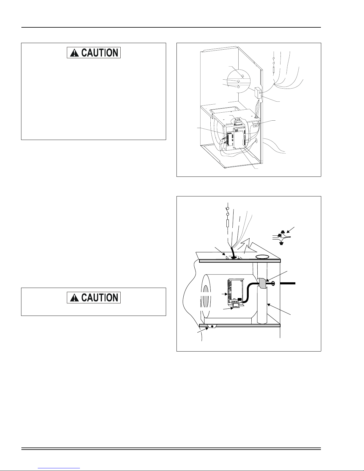
HORIZONTAL VENT APPLICATIONS
If installing a horizontal venting system, it is recommended
that a vent drain be added to the vent pipe to prevent the
accumulation of excess condensate in the inducer motor during operational cycles. Refer to Figure 31.
3.00” MINIMUM
LOOP DIA.
ATTACH THIS END
TO CONDENSATE
DRAIN SYSTEM
FIGURE 31 : Horizontal Vent Drain - Upflow Models
To install the vent drain, complete the following steps:
1. Place a tee of the proper diameter for the vent system
being installed (2" or 3") in the horizontal run closest to
the furnace.
2. Place a reducer bushing of proper diameter in the stem
portion of the tee. The recommended size for the
reducer is 5/8”.
3. Place a piece of 5/8” diameter or other selected size pipe
a minimum of 3" long into the reducer to serve as a
nipple.
NOTE: Tee, reducer and nipple must be properly cemented
together using the appropriate method and materials specified in the Combustion Air Intake/Vent Connections section of
these instructions.
4. Connect a piece of flexible drain tubing such as EPDM
rubber, Vinyl or PVC to the nipple.
5. Loop the drain tubing to provide a trap.
6. Connect the discharge end of the drain tube to the condensate disposal system externally to the furnace.
CONDENSATE PIPING
The condensate drain connection is packed in the furnace for
field installation. It consists of a formed hose with a 1/2” NPT
male connection. A 1/2” FM x 3/4” PVC slip coupling is
provided.
This drain hose may be installed to allow left or right side condensate drain connection. Refer to Figure 33. Cut the hose
to allow for proper fit for left or right exit.
LH DRAIN
3.00 MINIMUM
LOOP DIA.
RH DRAIN
ATTACH THIS END
TO CONDENSATE
DRAIN SYSTEM
FIGURE 33 : Condensate Piping - Upflow Models
.
To install the drain hose assembly, remove the 7/8” knockout
in the side panel. Remove the conduit nut from the 1/2” male
fitting. Push the male fitting through the hole and reinstall the
nut. The use of the 3/4” PVC coupling is optional.
FIGURE 32 : Horizontal Vent Drain -
Downflow/Horizontal Models
22 Unitary Products Group
Page 23

035-17468-001 Rev. A (801)
CONDENSATE
TRAP TUBING
FIGURE 34 : Downflow/Horizontal Models
CONVERSION FOR HORIZONTAL APPLICATIONS
Remove the condensate trap and its mounting bracket from
the unit side panel. Remove all drain hoses.
Reinstall the trap/bracket on the side panel which will be on
the bottom when the unit is located horizontally. Use the original mounting screws.
Refer to Figure 35 for hose locations and Table 7 on Page 23
for hose cut lengths. All hoses are identified as shown in Figure 35.
For horizontal left airflow (inducer and vent low) or horizontal
right airflow (inducer and vent high), install condensate drain
hoses as follows:
RIGHT AIRFLOW (Inducer High) - Three hoses are required.
Hoses are supplied with furnace. Refer to Figure 35 and
Table 7 on Page 23 for application.
LEFT AIRFLOW (Inducer Low) - Two hoses are required.
Inducer outlet to trap is supplied. Condensate pan to trap
must be field supplied using 5/8” I.D. hose material. Refer to
Figure 35 and Table 7 on Page 23, for hose placement and
sizing.
Table 7 : HORIZONTAL CONDENSATE DRAIN HOSE
SIZES - MODELS P*DH / FG9-DH / G9T-DH
CABINET SIZE (IN.)
DIM.
A 4-1/2 4-3/4 3-1/2 5-1/4
B 7-1/2 10-1/2 14 17-1/2
C 13-1/2 16-1/2 20 23-1/2
D 3-3/8 3-1/4 3-1/4 3-1/4
RIGHT AIRFLOW (INDUCER HIGH)
14-1/2 17-1/2 21 24-1/2
LEFT AIRFLOW (INDUCER LOW)
Plug all unused condensate trap, condensate pan
and inducer drain connection points using plugs
provided.
Drain Connection: The following steps apply to all models.
1. It is recommended that either 1/2” or 3/4” PVC or equivalent pipe be field installed as drain pipe. The condensate
piping may be tied together with the air conditioning condensate drain if the air conditioning condensate drain
line is trapped upstream of the tie-in and the combined
drains are constructed of the same material.
2. All pipe joints must be cleaned, de-burred and cemented
using PVC primer and cement.
3. The furnace contains an internal trap. Therefore, no
external trap should be used.
4. If a condensate pump is used, it must be suitable for use
with acidic water.
5. Where required, a field-supplied neutralizer can be
installed in the drain line, external to the furnace.
NOTE: The condensate drain from the furnace may be connected in common with the drain from an air conditioning coil
if allowed by local code. Follow the instructions with the coil
for trapping the drain.
Unitary Products Group 23
Page 24

RIGHT AIRFLOW
(INDUCER HIGH)
035-17468-001 Rev. A (801)
HOSE IDENTIFIER NUMBERS:
C
B
A
1
3
2
1. CONDENSATE PAN TO TRAP “A” DIMENSIONS.
2. INDUCER BOTTOM TO TRAP “B” DIMENSIONS.
3. INDUCER OUTLET TO TRAP “C” DIMENSIONS.
LEFT AIRFLOW
(INDUCER HIGH)
D
4
5
FIGURE 35 : Horizontal Application Condensate Drain Connection
SAFETY CONTROLS
Rollout Switch Controls:
burner box assembly. If the temperature in the burner com-
Control Circuit Fuse: A 3 amp. fuse is provided to protect
the 24 volt transformer from overload caused by control circuit wiring errors. This is an ATO 3, automotive type fuse and
is located in the unit wiring harness between the control
transformer and the furnace control.
Blower Door Safety Switch:
This unit is equipped with an
Electrical Interlock Switch mounted in the blower compartment. This switch interrupts all power at the unit when the
panel covering the blower compartment is removed.
partment exceeds its set point, the igniter control and the gas
valve are de-energized. The operation of this control indicates a malfunction in the combustion air blower, heat
exchanger or a blocked vent pipe connection. Corrective
action is required. This is a manual reset control and must be
reset before operation can continue.
Pressure Switches:
switches which monitor the flow through the combustion air/
vent piping system. These switches de-energize the ignition
control module and the gas valve if any of the following conditions are present.
1. Blockage of combustion air piping or terminal:
Blower and burner must never be operated without
the blower panel in place.
Electrical supply to this unit is dependent upon the panel that
2. Blockage of vent piping or terminal:
covers the blower compartment being in place and properly
positioned.
3. Failure of combustion air blower motor:
Main power to the unit must still be interrupted at the
main power disconnect switch before any service or
4. Blockage of condensate drain piping:
repair work is to be done to the unit. Do not rely
upon the interlock switch as a main power
disconnect.
5. Blockage of condensate drain piping (horizontal right
HOSE IDENTIFIER NUMBERS:
1. INDUCER OUTLET TO TRAP USE AS PROVIDED.
5. CONDENSATE PAN TO TRAP “D” DIMENSIONS.
This control is mounted on the
This furnace is supplied with pressure
• Low fire (1LP)
• High fire (2 LP)
• Low fire (1LP)
• High fire (2 LP)
• Low fire (1LP)
• High fire (2 LP)
• Low fire (1LP)
• High fire (2 LP)
installations only).
• Low fire (3 LP)
• High fire (3 LP)
24 Unitary Products Group
Page 25

035-17468-001 Rev. A (801)
R
E
P
L
A
C
E
S
C
R
E
W
LIMIT CONTROL
There are high temperature limit control(s) located on the furnace vestibule panel near the gas valve. These are automatic
reset controls and provide over temperature protection due to
reduced airflow, such as a dirty filter.
START-UP AND ADJUSTMENTS
The initial start-up of the furnace requires the following additional procedures:
1. When the gas supply is initially connected to the furnace,
the gas piping may be full of air. In order to purge this air,
it is recommended that the ground union be loosened
until the odor of gas is detected. When gas is detected,
immediately retighten the union and check for leaks.
Allow five minutes for any gas to dissipate before continuing with the start-up procedure.
Be sure proper ventilation is available to dilute and
carry away any vented gas.
b. The ignition module will energize (open) the main
gas valve on low fire for seven seconds.
c. After flame is established, the supply air blower will
start in about 30 seconds.
NOTE: Burner ignition may not be satisfactory on first startup due to residual air in the gas line or until gas manifold
pressure is adjusted. The ignition control will make 3 attempts
to light before locking out.
4. With furnace in operation, paint the pipe joints and valve
gasket lines with a rich soap and water solution. Bubbles
indicate a gas leak. Take appropriate steps to stop the
leak. If the leak persists, replace the component.
DO NOT omit this test! Never use a flame to check
for gas leaks.
GAS VALVE OPERATION
The electronic switch is a two-position (ON-OFF) type. To
turn the valve ON, flip the switch to line up the word ON on
the switch housing, Refer to Figure 36.
Perform the following procedures only after the condensate trap has been properly piped to a drain connection using the procedure in this instruction.
2. The condensate trap must be filled with water before putting the furnace into operation. The recommended procedure is as follows:
a. Disconnect the condensate drain hose from the
induced draft blower discharge.
b. Elevate this hose and fill with water using a funnel.
c. Replace the condensate drain hose and clamps.
NOTE: If this procedure is not followed, the unit may not
properly drain on initial start up.
3. All electrical connections made in the field and in the
factory should be checked for proper tightness.
IGNITION SYSTEM SEQUENCE
1. Turn the gas supply ON at external valve and main gas
valve.
2. Set the thermostat above room temperature to call for
heat.
3. System start-up will occur as follows:
a. The induced draft blower motor will start at high
speed and wait for low pressure switch contacts to
close, then switch to low speed and the hot surface
ignitor will glow for approximately 17 seconds.
PM
C
O
HI
INLET
F
F
ON
S
C
R
E
E
C
W
A
L
P
E
R
OUTLET
WRENCH
BOSS
ON / OFF SWITCH
LOW FIRE
REGULATOR
ADJUSTMENT
SEAL SCREW
HIGH FIRE
REGULATOR
LO ADJUST
HI ADJUST
ADJUSTMENT
SEAL SCREW
FIGURE 36 : Gas Valve (Top) Manual Control Knob
(Bottom) Regulator Adjustments
Unitary Products Group 25
Page 26

035-17468-001 Rev. A (801)
CHECKING GAS INPUT (NATURAL GAS)
NOTE: Front door of burner box must be secured when
checking gas input.
1. Turn off all other gas appliances connected to gas meter.
2. With the furnace turned on, measure the time needed for
one revolution of the hand on the smallest dial on the
meter. A typical domestic gas meter usually has a 1/2 or
1 cubic foot test dial.
3. Using the number of seconds for each revolution and the
size of the test dial increment, find the cubic feet of gas
consumed per hour from Table 4 on page 15.
NOTE: To find the Btuh input, multiply the number of cubic
feet of gas consumed per hour by the BTU content of the gas
in your particular locality. Contract your gas company for this
information, as it varies widely from city to city.
EXAMPLE:
It is found by measurement that it takes 26 seconds for the hand to turn on the 1 cubic foot dial to make a
revolution with only a 120,000 Btuh furnace running. Using
this information, locate 26 seconds in the first column of.
Read across to the column headed 1 Cubic Foot where you
will see that 138 cubic feet of gas per hour are consumed by
the furnace at that rate. Multiply 138 by 850 (the BTU rating
of the gas obtained from the local gas company). The result is
117,300 Btuh, which is close to the 120,000 Btuh rating of the
furnace.
If the actual input is not within +
2% of the furnace rating, with
allowance being made for the permissible range of the regulator setting (0.3 inches W.C.), replace the orifice spuds with
spuds of the proper size.
Be sure to relight any gas appliances that were
turned off at the start of this input check.
SECONDS FOR
ONE REVOLUTION
10 180 360
12 150 300
14 129 257
16 113 225
18 100 200
20 90 180
22 82 164
24 75 150
26 69 138
28 64 129
30 60 120
32 56 113
34 53 106
36 50 100
38 47 95
40 45 90
42 43 86
44 41 82
46 39 78
48 37 75
50 36 72
52 35 69
54 34 67
56 32 64
58 31 62
60 30 60
SIZE OF TEST DIAL
1/2 CUBIC
FOOT
1 CUBIC FOOT
26 Unitary Products Group
Page 27

035-17468-001 Rev. A (801)
ADJUSTMENT OF MANIFOLD GAS PRESSURE
Manifold gas pressure may be measured by two different procedures. It may be measured with the burner box cover in
place or it may be measured with the burner box cover
removed. Follow the appropriate section, 1a or 1b in the
instructions below.
1. Read the inlet gas pressure using either of the two
methods below.
a. Reading the gas pressure with the burner box
cover in place - Disconnect the pressure reference
hose from the right side of the burner box. Using a
tee fitting and a short piece of hose, connect the
negative side of the manometer to the burner box
pressure reference port. Connect the positive side
of the manometer to the adapter previously installed
in the gas valve, See Figure 37 or 38.
b. Reading the gas pressure with the burner box
cover removed - Remove the screws securing the
burner box front cover plate. Remove the cover. It is
gasketed and may stick in place. Connect the positive side of the manometer to the adapter previously
installed in the gas valve as shown in Figure 37 or
38. There will be no second connection to the
manometer as it will reference atmospheric pressure.
The regulated outlet pressures, both low and high, have been
calibrated at the factory. Additional pressure adjustment
should not be necessary. If adjustment is necessary, set to
the following specifications. After adjustment, check for gas
leakage.
Natural Gas
Low Fire 1.6 IWG
High Fire 3.5 IWG
WITH BURNER BOX COVER IN PLACE WITH BURNER BOX COVER REMOVED
High Outlet Pressure Adjustment
1. Turn off all electrical power to the system at main fuse or
circuit breaker.
2. Attach a manometer to the outlet pressure tap of the
valve.
3. Turn on power and energize main and redundant (P.M.)
solenoids as well as the HI terminal.
4. Remove high adjustment seal screw to expose the 3/32”
set screw (Refer to Figure 36).
5. To increase outlet pressure, turn the 3/32” set screw
clockwise. To decrease outlet pressure, turn the set
screw counterclockwise. Adjust regulator until pressure
shown on manometer matches the pressure specified on
the appliance rating plate.
6. Replace low adjustment seal screw and tighten securely.
Cycle the valve several times to verify regulator setting.
7. Remove manometer and replace the outlet pressure tap
plug.
Low Outlet Pressure Adjustment
1. Turn off all electrical power to the system at main fuse or
circuit breaker.
2. Attach a manometer to the outlet pressure tap of the
valve.
3. Turn on power and energize main and redundant (P.M.)
solenoids. Do not energize HI terminal.
4. Remove low adjustment seal screw, See Figure 36.
5. To increase outlet pressure, turn the 3/32” set screw
below the low adjustment seal screw clockwise. To
decrease outlet pressure, turn the set screw counterclockwise. Adjust regulator until pressure shown on
manometer matches the pressure specified on the appliance rating plate.
6. Replace high adjustment seal screw and tighten
securely. Cycle the valve two or three times to verify regulator setting.
7. Remove manometer and replace the outlet pressure tap
plug.
.
OUTLET
PRESSURE TAP
BURNER BOX PRESSURE
REFERENCE HOSE
BURNER BOX
WITH COVER
6
U-TUBE
MANOMETER
5
4
3
2
1
0
1
2
3
4
5
6
FIGURE 37 : Reading Gas Pressure - Upflow Models
Unitary Products Group 27
GAS VALVE
TEE
FITTING
3.5 IN
WATER COLUMN
GAS PRESSURE
SHOWN
OUTLET
PRESSURE TAP
BURNER BOX
WITH COVER
REMOVED
U-TUBE
MANOMETER
GAS VALVE
BURNER BOX
PRESSURE
REFERENCE HOSE
(NOT USED)
6
5
4
3
3.5 IN
2
1
WATER COLUMN
0
1
GAS PRESSURE
2
3
SHOWN
4
5
6
Page 28

035-17468-001 Rev. A (801)
WITH BURNER BOX COVER IN PLACE WITH BURNER BOX COVER REMOVED
BURNER BOX
BURNER BOX
PRESSURE
REFERENCE HOSE
TEE
FITTING
WITH COVER
GAS VALVE
U-TUBE
MANOMETER
OUTLET
PRESSURE
TAP
6
5
4
3
2
1
0
1
2
3
4
5
6
3.5 IN
WATER COLUMN
GAS PRESSURE
SHOWN
BURNER BOX
PRESSURE
REFERENCE
HOSE
FIGURE 38 : Reading Gas Pressure - Downflow/Horizontal Models
After about 20 minutes of operation, determine the furnace
temperature rise. Take readings of both the return air and the
heated air in the ducts, about six feet from the furnace where
The manifold pressure must be checked with the
screw-off cap for the gas valve pressure regulator in
place. If not, the nominal manifold pressure setting
will result in an over-fire condition.
If manifold pressure is too high, an over-fire condition exists which could cause heat exchanger failure. If the manifold pressure is too low, sooting and
eventual clogging of the heat exchanger could
occur.
Be sure that gas valve regulator cap is replaced and
burner box to gas valve pressure reference hose is
reconnected.
Once the correct gas pressure to the burners has been
they will not be affected by radiant heat.
Increase the blower speed to decrease the temperature rise;
decrease the blower speed to increase the rise.
All direct-drive blowers have multi-speed motors. The blower
motor speed taps are located in the control box in the blower
compartment.
You may select a heating speed and a cooling speed. They
may be the same speed or a different speed.
To use the same speed tap for heating and cooling, the heat
terminal and cool terminal must be connected using a jumper
wire and connected to the desired motor lead. Place all
unused motor leads on Park terminals. Two Park terminals
are provided.
established, turn the gas valve switch to OFF and turn the
electrical supply switch to OFF; then remove the pressure tap
at the gas valve and re-install the plug, using a compound (on
the threads) resistant to the action of LP gases. Replace the
burner box front cover or the pressure reference hose.
Turn the electrical and gas supplies back on, and with the
burners in operation, check for gas leakage around the plug
with a soap and water solution.
ADJUSTMENT OF TEMPERATURE RISE
DIRECT DRIVE MOTORS (ONLY APPLIES TO PSC
REPLACEMENT)
VARIABLE SPEED MOTORS
The temperature rise, or temperature difference between the
return air and the heated air from the furnace, must be within
the range shown on the furnace rating plate and within the
application limitations shown in Table 1 on Page 5 or Table 2
on Page 6.
The temperature rise, or temperature difference between the
return air and the heated air from the furnace, must be within
the range shown on the furnace rating plate. Application limitations are shown in Table 1 or 2. After the temperature rise
has been determined, the cfm can be calculated.
BURNER BOX WITH
COVER REMOVED
OUTLET
PRESSURE
TAP
6
5
4
GAS VALVE
U-TUBE
MANOMETER
3
2
1
0
1
2
3
4
5
6
3.5 IN
WATER COLUMN
GAS PRESSURE
SHOWN
Do not energize more than one motor speed at a
time or damage to the motor will result.
28 Unitary Products Group
Page 29

035-17468-001 Rev. A (801)
FURNACE ACCESSORIES
E
LECTRICAL
*ET03700324 Thermostat, One-stage Heat/One-stage Cool, non-programmable
*ET03700124 Thermostat, One-stage Heat/One-stage Cool, Deluxe programmable
*ET03770010124 Thermostat, Two-stage Heat/Two-stage Cool, non-programmable
*ET03700024 Programmable Thermostat, Two-stage Heat/Two-stage Cool, Deluxe programmable
NON-
ELECTRICAL
1NP0480 Propane Conversion Kit
1SR0302BK External Side Filter Rack (6-Pack)
1BR0317 External Bottom or Horizontal Filter Rack - Cabinet “B”
1BR0321 External Bottom Filter Rack - Cabinet “C”
1BR0324 External Bottom or Horizontal Filter Rack - Cabinet “D”
1NK0301 Condensate Neutralizer Kit
1PS0315 High Altitude Pressure Switch Kit - 60 / 55 / 1200 “B”
1PS0316 High Altitude Pressure Switch Kit - 80 / 75 / 1600 “C”
1PS0317 High Altitude Pressure Switch Kit - 100 / 95 / 2000 “C”
1PS0318 High Altitude Pressure Switch Kit - 120 / 112 / 2000 “D”
1CT0302 Concentric Vent Kit - 2”
1CT0303 Concentric Vent Kit - 3”
1CT0317 Combustible Floor Base - Cabinet “B”
1CT0324 Combustible Floor Base - Cabinet “D”
* Substitute 2 for York brands and 6 for non York brands.
AIRFLOW
D
C
B
A
COOL HEAT ADJ DELAY
HEAT PUMP HUMIDISTAT
FIGURE 39 : CFM Timer Board
CFM SELECTION BOARD
TAP SELECTION
D
C
B
A
REMOVE FOR
Unitary Products Group 29
Page 30

035-17468-001 Rev. A (801)
HEATING AIRFLOW
The heating airflow has been preset at the factory to provide
maximum CFM. If a lesser CFM is required for a specific
HVAC system the “JUMPER” on the HEAT selection pins on
the CFM-Timer Board may be moved to tap “B”, “C”, or “D”.
Pin “A” will provide the highest CFM and “D” the lowest CFM
(Refer to Tables 9 or 10).
NOTE: When changing jumper positions, make sure that the
jumper is pushed all the way on the pins. If the jumper is not
making good contact or is left off completely, the blower will
operate as if the jumper were in the “A” position.
NOTE: Power to the blower must be removed for at least 4
seconds after a heat or cool tap selection change, in order for
the motor to recognize an adjustment.
The fixed blower on delay and adjustable blower-off delay will
function as described in the “OPERATION AND
MAINTENANCE" Section on Page 32 of this instruction.
COOLING AIRFLOW
The cooling airflow is preset at the factory to provide approximately 90 percent of the maximum CFM and must be field
adjusted to match the HVAC system at installation. Refer to
the outdoor unit installation instruction for the recommended
airflow for the cooling system.
The "DELAY" Tap should be set in the "B" position for a twostage condenser. This results in a 45 second off delay at 82%
of the programmed cooling airflow with a 15-second coast to
stop. It should be set in the "C" position for a system with a
TXV or solenoid valve. This results in a 45 second off delay at
75% of the programmed cooling airflow with a 15-second
coast to stop. It should be set in the "D" position for a system
without a TXV or solenoid valve. This results in a 60 second
off delay at 82% of the programmed cooling airflow with a 15second coast to stop. The "A" position is the factory setting
and is used for test purposes. With the delay set in the “A”
position, the blower will operate at 100% of the programed
cooling air flow for 60 seconds, with a 15 second coast to
stop.
ADJUSTMENT OF FAN-OFF CONTROL SETTINGS
This furnace is equipped with a time-on/time-off heating fan
control. The fan-on is fixed at 30 seconds. The fan-off delay is
factory set to 60 seconds (refer to Table 8 and Figure 40),
however, it is field-adjustable to 90, 120 or 180 seconds. The
fan-off setting must be long enough to adequately cool the
furnace, but not so long that cold air is blown into the heated
space.
The continuous fan speed dip switch (switch 3) on the ignition
control has no affect on setting and should be left in the off
position, as continuous fan speed is determined by the vari-
Tab le 8: FAN CONTROL SETTINGS
IGNITION CONTROL
To Delay Fan-Off By:
60 Sec. On-On
90 Sec. Off-On
120 Sec. On-Off
180 Sec. Off-Off
OFF
SWITCH 3 SHOULD
BE LEFT IN “OFF”
POSITION
ON
COOL
HEAT LO
HEAT HI
LINE
WI
W2
Set Switch
1-2
FAN OFF
ADJUSTMENT
SWITCHES
Y
R
G
B
FIGURE 40 : Typical Heat/Cool Speed Tap
Connections (PSC Motor)
CONTINUOUS BLOWER
There are two modes of continuous blower operation. In one
mode the blower is controlled directly through the blower
motor. In the second mode the blower is controlled through
the ignition control. In the first mode, when the thermostat
fan-switch is set to the ON position a circuit is completed
between terminals “R” and “G” of the thermostat. The continuous fan speed will be 63% of the high cool speed. If more air
is desirable the green wire labeled (G Cool Speed) may be
connected to the “G” terminal of the ignition control to achieve
HIGH COOL speed (DIP switch number 3 on the ignition control must be in the OFF position). The air cleaner and the
blower motor are energized through the ignition control or
directly through the motor.
INTERMITTENT BLOWER COOLING
On cooling/heating thermostats with fan switch, when the fan
switch is set in the auto position and the thermostat calls for
cooling, a circuit is completed between the R, Y and G terminals. The motor is energized through the Y1 cool terminal
and runs on the speed selected on the CFM Timer board.
The fan off setting is fixed at 60 seconds for SEER enhancement.
30 Unitary Products Group
Page 31

035-17468-001 Rev. A (801)
Table 9 : AIRFLOW DATA - UPFLOW MODELS
HIGH/LOW SPEED COOLING AND HEAT PUMP CFM
P1XUB12V05501
G9V06012UPB11
High Low High Low High Low High Low COOL TAP ADJ TAP
1315 720 1655 930 2030 1090 2180 1210 A B
1095 610 1555 855 1780 945 1760 970 B B
1200 655 1510 830 1890 1000 2000 1100 A A
1010 545 1440 790 1630 850 1600 910 B A
1065 595 1375 755 1685 895 1780 990 A C
870 500 1350 745 1555 830 1540 860 C B
885 505 1280 700 1430 785 1410 820 B C
655 450 1150 620 1310 740 1300 770 D B
870 460 1230 670 1400 770 1400 800 C A
610 445 1030 555 1220 665 1220 710 D A
715 450 1120 600 1245 700 1230 740 C C
545 450 915 495 1075 605 1060 660 D C
P1XUC16V07501
G9V08016UPC11
P1XUC20V09501
G9V10020UPC11
P1XUD20V11201
G9V12020UPD11
JUMPER SETTINGS
HIGH/LOW HEAT CFM
P1XUB12V05501
G9V06012UPB11
High Low High Low High Low High Low HEAT TAP ADJ TAP
1020 665 1635 1065 1940 1225 1870 1205 A Any
925 610 1540 990 1745 1105 1715 1105 B Any
850 555 1400 890 1595 1010 1590 1020 C Any
785 515 1265 805 1475 930 1480 950 D Any
P1XUC16V07501
G9V08016UPC11
P1XUC20V09501
G9V10020UPC11
P1XUD20V11201
G9V12020UPD11
JUMPER SETTINGS
Table 1 0: AIRFLOW DATA - DOWNFLOW/HORIZONTAL MODELS
HIGH/LOW SPEED COOLING AND HEAT PUMP CFM
P1XDB12V07501
G9V08012DHB11
High Low High Low COOL TAP ADJ TAP
1345 740 2230 1290 A B
1120 620 1810 1025 B B
1225 675 2100 1150 A A
1020 560 1680 950 B A
1100 605 1850 1045 A C
880 490 1600 900 C B
920 505 1500 840 B C
660 450 1410 770 D B
800 450 1510 825 C A
600 420 1265 700 D A
720 440 1320 740 C C
545 420 1120 625 D C
P1XDD20V11201
G9V12020DHD11
JUMPER SETTINGS
HEATING AIRFLOW
P1XDB12V07501
G9V08012DHB11
High Low High Low COOL TAP ADJ TAP
1380 900 1925 1260 A Any
1260 820 1750 1165 B Any
1150 750 1600 1055 C Any
1075 700 1475 985 D Any
P1XDD20V11201
G9V12020DHD11
JUMPER SETTINGS
All CFM’s are shown at 0.5” w.c. external static pressure.
These units have variable speed motors that automatically
adjust to provide constant CFM from 0.0” to 0.6” w.c. static
pressure. From 0.6” to 1.0” static pressure, CFM is reduced
by 2% per 0.1” increase in static. Operation on duct systems
with greater than 1.0” w.c. external static pressure is not recommended.
Unitary Products Group 31
NOTE: At some settings, LOW COOL and/or LOW HEAT air
flow may be lower that what is required to operate an airflow
switch on certain models of electronic air cleaners. Consult
the instructions for the electronic air cleaner for further
details.
Page 32

035-17468-001 Rev. A (801)
OPERATION AND MAINTENANCE
SEQUENCE OF OPERATION
The following describes the sequence of operation of the furnace as it relates to a furnace equipped with a variable speed
blower. Refer to the schematic wiring diagram for component
location on Page 39 or 40.
HEATING OPERATIONAL SEQUENCE
TWO STAGE THERMOSTAT
The ignition control in this furnace is unique to this product.
The control allows for a 24 volt or a 115 volt circulator input/
output. This allows for the replacement of the variable speed
motor with a multi-speed PSC motor in the event a variable
speed motor is not available at the time of servicing.
In a typical system, a call for first stage heat is initiated by
closing the W1 thermostat contacts. The inducer blower is
energized at high speed and the control waits for the low
pressure switch contacts to close. The inducer blower is
energized at low speed and the 120 VAC silicon carbide
ignitor is powered.
At the end of the ignitor warm-up time, the first stage of the
two stage gas valve is energized (low fire). Flame must be
detected within 7 seconds. If flame is detected, the delay-tofan-on period begins. After the delay-to-fan-on period ends,
the circulator fan is energized at low heat speed and the air
cleaner and humidifier are energized.
A call for second stage heat (W1 and W2) after a call for first
stage heat will energize the inducer at high speed and energize the circulator at high heat speed. The circulator will energize at high heat speed after 30 seconds with a call for
second stage heat. If the furnace has been operating in first
stage heat for more than 30 seconds and the control receives
a call for second stage heat, the blower will immediately
switch to high speed. The second stage pressure switch contacts will close and energize the second stage gas valve (high
fire).
If a call for second stage heat occurs at the same time as a
call for first stage heat, the second stage heat is energized
immediately after flame rectification is sensed on first stage.
When the second stage of the thermostat is satisfied, the
inducer motor is reduced to low speed and the 2nd stage gas
valve is de-energized to 1st stage. The circulator remains on
high heat speed for 30 seconds then de-energizes to low
heat speed.
When the first stage of the thermostat is satisfied, the gas
valve is de-energized and the heat delay to fan off begins timing. The inducer will postpurge for an additional 15 seconds,
then the inducer and humidifier will de-energize. Upon completion of the heat delay-to-fan-off, the circulator and air
cleaner are de-energized. Control timing, refer to (Refer to
Figure 41 on Page 33).
If flame is not detected during the trial for ignition period, the
gas valve is de-energized, the ignitor is turned off and the
ignition control goes into the “re-try” sequence.
The ”re-try” sequence provides a 60 second wait with inducer
interpurge following an unsuccessful ignition attempt (flame
not detected). After this wait, the ignition sequence is
restarted with an additional 10 seconds of ignitor warm-up
time. Two retries will be attempted before the control goes
into system lockout. If flame is established for more than 10
seconds after ignition, the ignition controller will clear the ignition attempt (or retry) counter.
If flame is detected, then lost, the ignition control will repeat
the initial ignition sequence. After 5 attempts to sustain flame,
the control will go into system lockout.
During burner operation, a momentary loss of power of 50
milliseconds or longer will de-energize the main gas valve.
When power is restored, the gas valve will remain
de-energized and a restart of the ignition sequence will begin
immediately.
A momentary loss of gas supply, flame blowout, or a shorted
or open condition in the flame probe circuit will be sensed
within 0.8 seconds. The gas valve will de-energize and the
control will restart the ignition sequence.
Recycles will begin and the burner will operate normally if the
gas supply returns, or the fault condition is corrected, before
the last ignition attempt. Otherwise, the control will go into
system lockout.
If the control has gone into system lockout, it may be possible
to reset the control by a momentary power interruption of one
second or longer. Refer to the FURNACE CONTROL DIAGNOSTICS on Page 37 of this instruction for reset information.
32 Unitary Products Group
Page 33

035-17468-001 Rev. A (801)
W2 SIGNAL
HIGH INDUCER
HIGH STAGE PRESSURE
SWITCH AND 2ND STAGE
MAIN VALVE
CIRCULATOR HIGH
HEAT SPEED
2ND STAGE
HIGH LIMIT
W1 SIGNAL
LOW
INDUCER
ON
OFF
ON
OFF
ON
OFF
ON
OFF
CLOSED
OPEN
ON
OFF
ON
OFF
CALL HIGH HEAT AFTER LOW
HEAT IS ESTABLISHED
HIGH
HEAT
OFF
DELAY
30 SEC.
CLOSED
OPEN
ON
OFF
ON
OFF
PRESENT
ABSENT
ON
OFF
LOW PRESSURE
SWITCH CLOSE
RECOGNITION
HSI
WARM
UP
17 SEC.
IGNITION
ACTIVATION
PERIOD
4 SEC.
TRIAL FOR
IGNITION
7 SEC.
LOW CIRCULATOR
HEAT SPEED
NOTE:
LOW STAGE
PRESSURE
SWITCH
HSI
1ST STAGE
MAIN VALVE
FLAME
SENSE
1ST STAGE
1. THIS DIAGRAM SHOWS TWO IGNITION ATTEMPTS
2. TIMING LENGTHS ARE NOT TO SCALE
FIGURE 41 : Sequence Timing for Ignition Control
INTERPURGE
60 SEC.
IGNITION
DEACTIVATION
PERIOD
3 SEC.
HSI
WARM
UP
27 SEC.
HEAT FAN
DELAY ON
30 SEC.
BURN
TIME
POST
PURGE
15 SEC.
HEAT FAN DELAY OFF
SELECTABLE
60,90,120,180 SEC.
Unitary Products Group 33
Page 34

035-17468-001 Rev. A (801)
SINGLE STAGE THERMOSTAT
If a single stage thermostat is used the unit will be controlled
through the CFM Timer board timer adjustment pins (Refer to
Figure 13 on Page 13.). For the furnace to operate on High
Fire the timer jumper must be placed on the 10, 15 or 20
minute adjustment terminals. On a call for heat the unit will
operate on low fire as detailed above. If the heating requirements cause the cycle to exceed the jumper settings, the
high fire timer will energize the second stage heat. The second stage operation will function as detailed above. The heating cycle will be completed in high fire operation. If the timer
jumper is in the “TIME OFF” position with a single-stage thermostat, the unit will stay in low fire operation.
HOT SURFACE IGNITION SYSTEM
Do not attempt to light this furnace by hand (with a
match or any other means). There may be a potential shock hazard from the components of the hot
surface ignition system. The furnace can only be lit
automatically by its hot surface ignition system.
MAINTENANCE
AIR FILTERS
The filters should be checked periodically for dirt accumulation. Dirty filters greatly restrict the flow of air and overburden
the system.
Clean the filters at least every three months. On new construction, check the filters every week for the first four weeks.
Inspect the filters every three weeks after that, especially if
the system is running constantly.
All filters used with the furnace are the high velocity, cleanable type. Clean these filters by washing in warm water.
Make sure to shake all the water out of the filter and have it
reasonably dry before installing it in the furnace. When
replacing filters, be sure to use the same size and type as
originally supplied.
UPFLOW FILTER REMOVAL AND REPLACEMENT
1. Turn off electrical power supply to the furnace at disconnect switch. Remove access doors.
2. In the blower compartment disengage the looped end of
the filter retainer wire from the front edge of the cabinet.
The wire will now pivot on the hinged ends at the rear of
the cabinet. (Refer to Figure 4 on Page 8)
3. Remove the filter and follow the cleaning instructions
above. DO NOT remove the filter stiffener rods, if provided.
4. When reinstalling the filter, be sure the filter completely
covers the cabinet opening and is secured in place by
the wire retainer.
LUBRICATION
Blower and ventor motors in these furnaces are permanently
lubricated and do not require periodic oiling.
BLOWER CARE
Label all wires prior to disconnecting when servicing
controls. Wiring errors can cause improper and dangerous operation. Verify proper operation after servicing.
Even with good filters properly in place, blower wheels and
motors will become dust laden after long months of operation.
The entire blower assembly should be inspected annually. If
the motor and wheel are heavily coated with dust, they can
be brushed and cleaned with a vacuum cleaner.
The procedure for removing the direct drive blower assembly
for cleaning is as follows:
1. Disconnect the electrical supply to the furnace and
remove the access doors.
2. Remove blower assembly mounting screws and slide the
blower assembly out of the slots in the deck. If the two
shipping screws were not previously removed, also
remove and discard these two screws located on each
front corner of the blower assembly.
3. To reassemble, reverse the procedure, restore power to
the furnace and verify operation.
BURNER AND FLAME SENSOR REMOVAL/CLEANING
The main burners and flame sensor should be checked periodically for dirt accumulation or oxidation.
If cleaning is required, follow this procedure:
1. Turn off the electrical power to the unit.
2. Turn off the gas supply at the external manual shutoff
valve and loosen the ground union joint.
3. Remove the upper access panel and remove the burner
box cover.
4. Remove the screws that hold the burner box assembly to
the vest panel and remove the assembly.
5. Remove burners from the burner assembly.
6. Burners may be cleaned by rinsing in hot water.
7. Reassemble the burners in the reverse order.
8. Remove the retaining screw to the flame sensor and
remove the sensor from the burner box. Clean the flame
sense rod with steel wool and replace.
34 Unitary Products Group
Page 35

035-17468-001 Rev. A (801)
CLEANING THE HEAT EXCHANGER
1. Turn off the main manual gas valve external to the
furnace.
2. Turn off electrical power to the furnace.
3. Remove the upper access panel and remove the burner
box cover.
4. Disconnect wires from flame sensor, rollout switch and
HSI igniter. Remove igniter carefully, as it is easily
broken.
Label all wires prior to disconnection when servicing
controls. Wiring errors can cause improper and dangerous operation. Verify proper operation after servicing.
5. Remove the screws that hold the burner box assembly to
the vestibule panel and remove the assembly. The lower
portion of the heat exchanger will now be exposed.
6. Remove the upper cover plate at the top of the furnace.
Remove the internal baffle.
7. The upper portion of the heat exchanger is now
exposed.
8. With a long flexible wire brush, clean inside each tube at
both the top and bottom. The brush must pass around
the rear heat exchanger tubes. Vacuum loose scale and
dirt from each tube.
9. Clean - vacuum all burners.
10. Replace all components in reverse order. Reconnect all
wiring.
11. Restore electrical power and gas supply to the furnace.
12. Check furnace operation.
CLEANING THE SECONDARY HEAT EXCHANGER
1. Follow steps 1 thru 10 under Cleaning the Primary Heat
Exchanger.
2. Remove the vent piping from the venter housing. Disconnect the drain lines from the venter and from the condensate drain pan. Remove the venter blower and the
condensate pan. The turbulators can then be gently
removed from the secondary heat exchanger.
3. With a stiff wire brush, brush out loose scale or soot.
4. Vacuum the secondary heat exchanger.
5. Finish the cleaning procedure by following steps 10 thru
12 under Cleaning the Primary Heat Exchanger.
VENT/AIR INTAKE
Should it be necessary to service the vent/air intake system,
the manufacturer recommends this service be conducted by
a qualified service agency.
The operation of this appliance requires the reassembly and
resealing of the vent/air intake system.
TROUBLESHOOTING
The following visual checks should be made before troubleshooting:
1. Check to see that the power to the furnace and the ignition control module is ON.
2. The manual shutoff valves in the gas line to the furnace
must be open.
3. Make sure all wiring connections are secure.
4. Review the sequence of operation.
Start the system by setting the thermostat above the room
temperature. Observe the system's response. Then use the
troubleshooting section in this manual to check the system's
operation.
TROUBLESHOOTING THE BLOWER ASSEMBLY
Check to see that there is power to the furnace and the ignition circuit module by turning the furnace power OFF for 5
seconds then ON. The red ignition control LED should light
for an instant then go out.
NO AIRFLOW OR MOTOR DOESN’T RUN
• Verify that the blower wheel is properly tightened on the
motor shaft.
• Verify 115 Volts AC at the power connector at the motor.
• Be sure the connectors at the motor, ignition control and
CFM Selection Board are properly connected and fully
seated.
• Switch the thermostat to CONTINUOUS FAN mode. If
the motor does not run, verify 24 VAC on the R to C
lines. If there is no voltage correct the cable/wiring, transformer fault. If there is voltage at the connector, the
motor has failed.
• Check High Heat, Low Heat or Cool output terminals for
24 volts.
• Check motor for tight shaft.
• Perform Moisture Check. Be sure motor connectors are
facing down. Arrange the wire harness to create a drip
loop under the motor. Check for plugged condensate
drain. Check for low airflow. Check and plug leaks in
return ducts.
MOTOR ROCKS BUT WON’T START
• Check for loose or compliant motor mount.
• Perform motor/control replacement check.
MOTOR OPERATION IS INTERMITTENT
• Verify that all connectors are firmly seated. Gently pull
the motor connector wires at both ends of the cables
individually to be sure they are properly crimped into the
housings.
MOTOR RUNS WHEN IS SUPPOSED TO BE OFF
• Allow a few minutes for the motor to shut off. Motor-off
delays are controlled by the ignition control.
Unitary Products Group 35
Page 36

035-17468-001 Rev. A (801)
MOTOR STARTS BUT: RUNS ERRATICALLY
• Check the line voltage for variation.
• Check low voltage connections at motor, unseated pins
in motor harness connectors.
• Check “Bk” for erratic CFM command.
MOTOR HUNTS OR “PUFFS”
• Excessive restriction in duct system or filter. Reduce
maximum air flow.
STAYS AT LOW CFM DESPITE SYSTEM CALL FOR COOL
OR HEAT CFM
• Check low voltage wires and connections.
• Verify fan is not in delay mode - wait until delay is complete.
• “R” missing /not connected at motor or terminal strip.
• Perform motor/control replacement check.
STAYS AT HIGH CFM
• “R” missing/not connected at motor or terminal strip.
• Is fan in delay mode? Wait until delay is complete.
• Perform motor/control replacement check.
BLOWER WON’T SHUT OFF
• Current leakage from controls into G, Y, or W? Check for
Triac switched thermostat or solid state relay.
EXCESSIVE NOISE
• Determine if it’s air noise, cabinet, duct, or motor noise.
AIR NOISE
• Check for loose blower housing, panels, etc.
• High static creating high blower speed.
REPLACEMENT OF FAILED MOTOR CONTROL MODULE
NOTE: The motor control module may be removed and
replaced without voiding the GE warranty.
You must have the correct replacement control module for the furnace being serviced. The controls are
factory programmed for specific operating modes.
Consult the parts list supplied with this furnace to
obtain the correct part number before ordering the
part.
Using the wrong control module voids all product
warranties and may produce unexpected results.
BLOWER REMOVAL FOR CONTROLLER REPLACEMENT
• Refer to BLOWER CARE on Page 34 of this manual for
blower removal instructions.
• Rest the blower on its side so the end of the motor is
accessible and facing up.
• Wait at least 5 minutes after disconnecting AC power
from the furnace before opening the motor.]
• Remove the 2-1/4” Hex head bolts from the motor while
holding the control module.
When the hex bolts are removed from the control
module, the module is free from the motor but still
connected by a plug and cable. Carefully rotate the
control so as to gain access the plug on the end of
cable. Squeeze the release latch and gently pull the
plug out of the control module. Do not pull on the
wires.
• Verify with an ohmmeter that the resistance of each
motor lead is greater than 100K ohms by connecting one
meter lead to the motor lead and the other to an
unpainted portion of the motor housing. If any one of the
leads fails this test THE MOTOR IS DEFECTIVE AND
MUST BE REPLACED.
• Verify that the replacement control module is the correct
one and carefully orient the control module close to the
motor so the cable can be plugged into the module. BE
SURE THE PLUG LATCHES WITH A CLICK.
• Carefully align the locating pin of the control module with
the matching motor hole. Replace the 2-1/4” hex head
bolts and tighten snugly. DO NOT OVERTIGHTEN.
REPLACEMENT OF THE VARIABLE SPEED MOTOR
WITH A PSC DIRECT DRIVE MOTOR
NOTE: A failed variable speed motor should always be
replaced with a variable speed motor suitable for the furnace
model being serviced. However, if one is not available, a 3
speed direct drive motor may be used in the interim.
REMOVAL OF THE VARIABLE SPEED BLOWER ASSEMBLY AND MOTOR
Follow the Blower Removal Instructions in the Maintenance
section of this instruction under, BLOWER CARE on Page
34.
1. Loosen the blower wheel set screw and the motor mount
bolt, and slide the variable speed motor out of the blower
housing.
36 Unitary Products Group
Page 37

035-17468-001 Rev. A (801)
INSTALLATION OF PSC MOTOR
1. Install the PSC direct drive motor into motor mount.
2. Slide motor in motor mount insuring there is no interference between moving and stationary parts. Position wire
leads downward. Tighten motor mount band screw to 30
8. Connect white main harness lead to Line neutral.
9. Connect motor leads to cool, heat lo and heat high per
electrical wire diagram table in the Installation manual.
10. Connect brown capacitor leads from motor to capacitor
and cover terminals with boot supplied.
in. lbs.
3. Center the blower wheel in the blower housing and align
the shaft flat with the blower wheel set screw. Tighten set
screw to 30 in. lbs.
4. Replace blower assembly and fasten with 5 screws
5. Strap motor capacitor to electric panel. Refer to Table 11
on page 37, for proper capacitor selection.
6. Fasten electric panel to blower housing.
7. Remove red wire from Circ. input terminal. Plug jumper
wire (attach to motor power harness) on 120 volt line ter-
POWER SUPPLY POLARITY - Ignition Control
If the power supply polarity is reversed, the following unit
operation will occur. On a call for heat, the inducer will run,
the HSI will glow and the gas valve will energize and the
burners will ignite. The burners will immediately extinguish
and the unit will recycle. This will occur 3 times and then
the unit will lockout. A “7” flash code will be displayed. This
code means the flame could not be established. This
occurs because the control cannot sense flame with the
power supply polarity reversed.
minal on ignition control and jumper to Circ. Input. Connect brown door switch wire to jumper.
Table 11: PSC MOTOR SELECTION
UPFLOW MODELS
Model Number Motor Part Number Motor Horsepower Capacitor Part Number Capacitor Rating MF
60 / 55 / 1200 / B 024-23271-000 1/2 024-20045-000 7.5
80 / 75 / 1600 / C 024-26002-000 3/4 024-20046-000 10.0
100 / 95 / 2000 / C 024-23288-001 1 024-20446-000 15.0
120 / 112 / 2000 / D 024-23238-001 1 024-20446-000 15.0
DOWNFLOW/HORIZONTAL MODELS
Model Number Motor Part Number Motor Horsepower Capacitor Part Number Capacitor Rating MF
80 / 75 / 1200 / B 024-23271-000 1/2 024-20045-000 7.5
120 / 112 / 2000 / D 024-23238-001 1 024-20446-000 15.0
FURNACE CONTROL DIAGNOSTICS
The furnace has built-in, self diagnostic capability. If a system
problem occurs, a fault code is shown by a blinking LED. It is
located behind a clear view port in the blower compartment
door. DO NOT remove the furnace blower compartment
panel OR turn off furnace power as either action will clear the
control's memory of the fault.
The control continuously monitors its own operation and the
operation of the system. If a failure occurs, the LED will indicate the failure code. If the failure is internal to the control, the
light will stay on continuously. In this case, the entire control
should be replaced as the control is not field repairable.
If the sensed failure is in the system (external to the control),
the LED will flash in the following flash-pause sequences to
indicate failure status.
Flash sequence codes 1 thru 4 are as follows. LED will turn
on for 1/4 second and off for 1/4 second. This pattern will be
repeated the number of times equal to the code. For example, two on flashes equals a number 2" fault code.
All flash code sequences are broken by a 2 second off period.
IGNITION CONTROL (P/N 031-01909-000)
Normal flame sense current is approximately
µ
2.4 microamps DC (
a)
Low flame signal control lockout point is
µ
0.15 microamps (DC (
CONTINUOUS FLASH (1 sec on - 1 sec off):
a)
This indicates that flame was sensed when there was not a call for
heat. With this fault code the control will also turn on both the
inducer motor and supply air blower. This fault would typically
be caused by a gas valve that leaks through or is slow closing.
2 FLASH:
This indicates that the normally open pressure
switch contacts are stuck in the closed position. The control
confirms these contacts are open at the beginning of each
heat cycle. This would indicate a faulty pressure switch or
mis-wiring.
Unitary Products Group 37
Page 38

035-17468-001 Rev. A (801)
3 FLASH: This indicates the normally open pressure switch
contact did not close at the beginning of the heat cycle. This
could be caused by a number of problems; faulty inducer,
blocked vent pipe, high winds at vent terminal, broken pressure switch hose or faulty pressure switch.
4 FLASH:
This indicates that a primary limit, or auxiliary limit,
or rollout limit switch has opened its normally closed contacts.
With this fault code the control will operate the supply air
blower and the ventor. This condition may be caused by: dirty
filter, improperly sized duct system, incorrect blower speed
setting, incorrect firing rate or faulty blower motor. The rollout
control is manually reset. If it has opened, check for proper
combustion air, proper inducer operation, primary heat
exchanger failure or burner problem. Be sure to reset the
switch after correcting the failure condition.
6 FLASH:
This indicates that after the unit was operating, the
pressure switch opened 5 times during the call for heat. This
could be caused by a number of problems; blocked vent or
chimney, faulty inducer, cracked pressure switch hose. The
ignition control will lock-out after the pressure switch opens 5
times.
7 FLASH:
This fault code indicates that flame could not be
established. This no-light condition occurred 3 times during
the call for heat before locking out. This may be caused by
low gas pressure, faulty gas valve, faulty hot surface igniter,
reversed line polarity, or burner problem.
8 FLASH:
This fault is indicated if the flame is lost 5 times
during the heating cycle.This could be caused by low gas
pressure or faulty gas valve. The ignition control will lock-out
if the flame is lost 5 times.
LED ON CONSTANTLY: This indicates an internal fault in the
furnace control discovered during its self-check procedure.
Replace the control.
60 MINUTE AUTOMATIC RESET FROM LOCKOUT:
This
control includes a watchdog type circuit that will reset from a
lockout condition after 60 minutes. This provides protection to
an unoccupied structure if a temporary conditions exists
causing a unit malfunction. An example would be a low
incoming gas supply pressure condition preventing unit operation. When the gas pressure was restored, at some point the
watchdog would restart the unit and provide heat for the
house.
NOTE: The control will blink one time when initially powered.
This is normal and not an indication of any malfunction.
RESET FROM LOCKOUT:
To reset the control from any
lockout condition break the line voltage supply or 24 volt signal from the thermostat for 30 seconds.
Do not try to repair controls. Replace defective controls with Source 1 Parts.
Never adjust pressure switch to allow furnace operation.
Never jump pressure switch or rewire in an attempt
to allow furnace operation. To do so will allow furnace to operate under potentially hazardous conditions.
38 Unitary Products Group
Page 39

035-17468-001 Rev. A (801)
ELEMENTARY DIAGRAM
--CAUTION
CONNECTION DIAGRAM
WIRING DIAGRAM - UPFLOW MODELS
NOTE: The furnace’s control system requires correct polarity of the power supply.
CONNECTION DIAGRAM
GND
GRN
BLK
P8/S8
ICM
H
COOL
YEL/BLK
WHT
BRN
MOTOR
BLOWER
S7
RED
M
P1/S1
120
2STAGE
GAS VALVE
MAIN
C
HI
P
5
/
S
5
BLK
WHT
YEL
GRN
AA
RV
T
LC
HUM
EAC
VAC
B
G
R
Y
BLU/WHT
W2
W1
BLU
ELEMENTARY DIAGRAM
GND
GRN
SEE NOTE 1
POWER SUPPLY120-1-60
DS
LS1
FLAME
C
1LP
NO
WHT
BLU
1
2
0
O
T
V
A
C
3A
XFMR
EAC
HEAT LO
CIRC IN
LINE
HEAT HI
HUM
WHT
BRN
BRN
BLK
BLK
BRN
RED
BRN
BLK
RED
BRN
RED
120V
NO
DOOR
N.O. SW
PRI
C
24V SEC
COM
BLK
BLU
120
VAC
GRN
BLK
BLK
GND
P4/S4
120VAC
LINE
SENSOR
ROS1
C
PUR
ORG
2LP
NO
BLK
3
1
2
WHT
5
4
6
BLK
7
9
8
BLU
11
10
12
BLU
RED
N1
E2
P2/S2
3
2
1
WHT
BLK
BRN
RED
WHT
BRN
RED
1
1
3
2
2
WHT
BLK
REDRED
VENTOR
MOTOR
GRN
GND
UO
LINE
XFMR
5
4
BLK
WHT
WHT
2
1
P3/S3
WHT
WHT
IGNITER
HOT SURFACE
9
1
MOTOR
BLOWER
ORG
BLK
BLK
WHT
GRN
--CAUTION
BRN
BLK
EAC
EAC
GRN
RED
RED
RED
EAC
OPEN ALL DISCONNECTS BEFORE
1
4
3
6
P6
BRN
YEL
YEL
WHT
SERVICE THIS UNIT
BLU
BLU/WHT
YEL/BLK
YEL/BLK
GRN
BLK
PUR
HUM
HUMIDIFIER
HUM
LEGEND
FUSE
16
P7
8
HIGH
1LP PRESSURE SW, FIRST STAGE
YEL/BLK
GRN
YEL
RED
BRN
BLK
ORG
9
VENTOR
2LP PRESSURE SW, SECOND STAGE
16
P9
MOTOR
LOW
24V CONNECTION ROOM THERMOSTAT
1T TRANSFORMER 40VA
W1
W2
S6
S9
8
BLK
PUR
YEL
WHT
RED
BLK
BLK
1
IGN
FACTORY WIRING AND DEVICES
FIELD WIRING AND DEVICES
FIELD CONNECTION
MINUTE SELECT
TIMEROFF
ADJ
DELAYHEATCOOL
CFM TIMERBOARD
1T (40VA)
COM
PRI
120V
3A
CONTROL BOARD
RELAY CONTACTS ON IGNITION
X/L
O
CG
W2
W1
R
Y
Y1
Y2
HUM
HUMIDISTAT
HEATPUMP
24V SEC
R
R
SEE NOTES
NOTES:
B/C
G
G
GV GAS vALVE
DS DISCONNECT SWITCH
(B) CANADIAN ELECTRICAL CODE (CEC) AND/OR
ALL FIELD WIRING PER: (A) NATIONAL ELECTRICAL CODE (NEC) AND/OR
1.
GRN
Y
Y
IGN HOT SURFACE IGNITOR
P1/S1 - 12 PIN PLUG & SOCKET ON IGN. CONTROL BOARD
(C) LOCAL OR CITY CODES.
IF ANY OF THE ORIGINAL WIRE AS SUPPLIED WITH THE FURNACE
2.
P2/S2 - 5 PIN PLUG & SOCKET ON IGN. CONTROL BOARD
P3/S3 - 2 PIN PLUG & SOCKET AT HOT SURFACE IGNITOR
HAVING ATEMPERATURE RATING OF AT LEAST 22.1°F (105 HAVING A
MUST BE REPLACED, IT MUST BE REPLACED WITH WIRINGMATERIAL
P4/S4 - 3 PIN PLUG & SOCKET AT INDUCER MOTOR
TEMPERATURE RATING OF ATLEAST 221°C).
LS1
ROS1
1LP
P5/S5 3 PIN PLUG & SOCKET ON VALVE
GV
C
NO
W1
W
P7/S7 - 16 PIN PLUG & SOCKET FOR MOTOR
P6/S6 - 6 PIN PLUG & SOCKET ON CFM TIMER BOARD
ALL REPLACEMENT COMPONENTS MUST BE PROPERLY GROUNDED.
CONNECTIONS SUITABLE FOR COPPER CONDUCTORS ONLY.
4.
3.
1ST STAGE
W2
Ls1 - PRIMARY LIMIT SWITCH
P8/S8 5 PIN PLUG & SOCKET ON ICM BLOWER MOTOR
P9/S9 - 16 PIN PLUG & SOCKET ON CFM TIMER BOARD
MOTORS ARE INHERENTLY PEOTECTED.
PROVIDE DISCONNECTS FOR ALL POWER SUPPLIES.
5.
6.
2LP
ROS1 - ROLL OUT SWITCH, LEFT SIDE
TIMER JUMPER MUST BE IN OFF POSITION WHEN USING A TWO STAGE THERMOSTAT.
7.
90% UPFLOW TWO-STAGE FURNACE - VARIABLE SPEED
C
NO
2ND STAGE
FIGURE 42 : Upflow Models
Unitary Products Group 39
N.O. SW
C
NO
DOOR SWITCH
RELAY
IGNITER
ON
AUTO
COOL
HEAT
OFF
HEAT/COOLTHERMOSTAT
Page 40

WIRING DIAGRAM - DOWNFLOW/HORIZONTAL MODELS
ELEMENTARY DIAGRAM
NOTES:
LEGEND
--CAUTION
CONNECTION DIAGRAM
NOTE: The furnace’s control system requires correct polarity of the power supply.
CONNECTION DIAGRAM
GND
GRN
BLK
P8/S8
ICM
BLOWER
S7
H
COOL
YEL/BLK
WHT
BRN
MOTOR
RED
LS1
ROS1
WHT
NO
1LP
BLU
1
2
0
O
T
V
A
XFMR
EAC
HEAT LO
CIRC IN
LINE
HEAT HI
HUM
WHT
BRN
BRN
BLK
BRN
RED
BRN
BLK
RED
120V
PRI
COM
BLU
GRN
BLK
GND
120VAC
LINE
RED
C
RED
C
3A
BLK
RED
BRN
NO
DOOR
C
24V SEC
BLK
120
VAC
BLK
P4/S4
WHT
FLAME
SENSOR
ROS 2
RED
LS2
RED
P2/S2
3
4
2
1
WHT
BLK
BRN
RED
N.O. SW
WHT
BRN
RED
1
1
3
2
2
WHT
BLK
RED
VENTOR
MOTOR
GRN
GND
C
PUR
ORG
2LP
NO
BLK
3
1
2
WHT
5
4
6
BLK
7
9
8
BLU
11
10
12
BLU
RED
N1
E2
UO
XFMR
LINE
5
BLK
WHT
WHT
2
1
120
P3/S3
WHT
WHT
IGNITER
HOT SURFACE
M
P1/S1
T
VAC
MAIN
2STAGE
--CAUTION
GAS VALVE
C
HI
P
5
/
S
5
BLK
WHT
YEL
GRN
GND
GRN
B
G
R
Y
BLU/WHT
AA
RV
LC
W2
W1
HUM
EAC
BLU
SEE NOTE 1
POWER SUPPLY120-1-60
ELEMENTARY DIAGRAM
DS
ORG
9
1
BLK
MOTOR
BLOWER
GND.
SERVICE THIS UNIT
OPEN ALL DISCONNECTS BEFORE
GRN
RED
BLK
BRN
BLK
WHT
RED
EAC
EAC
LEGEND
24V CONNECTION ROOM THERMOSTAT
1LP PRESSURE SW, FIRST STAGE
2LP PRESSURE SW, SECOND STAGE
YEL/BLK
GRN
YEL
RED
BRN
BLK
ORG
3LP PRESSURE SW, CONDENSATE
16
9
1T TRANSFORMER 40VA
S6
S9
8
1
P9
FIELD CONNECTION
W1
W2
BLK
PUR
YEL
WHT
RED
BLK
BLK
FUSE
BLU
BLU/WHT
1
4
6
3
P6
YEL/BLK
RED
BRN
YEL
GRN
YEL/BLK
16
P7
8
BLK
YEL
WHT
PUR
FACTORY WIRING AND DEVICES
ADJ
DELAYHEATCOOL
RELAY CONTACTS ON IGNITION
FIELD WIRING AND DEVICES
MINUTE SELECT
TIMEROFF
CFM TIMERBOARD
CONTROL BOARD
X/L
O
CG
W2
W1
R
Y
Y1
Y2
HUM
HUMIDISTAT
HEATPUMP
SEE NOTES
NOTES:
(B) CANADIAN ELECTRICAL CODE (CEC) AND/OR
ALL FIELD WIRING PER: (A) NATIONAL ELECTRICAL CODE (NEC) AND/OR
1.
GND.
DS DISCONNECT SWITCH
(C) LOCAL OR CITY CODES.
HUM
IGN
1T (40VA)
COM
PRI
120V
EAC
HUM
HUMIDIFIER
HIGH
MOTOR
VENTOR
LOW
3A
LS2
ROS2
24V SEC
R
R
C
3LP
NO
Y
G
B/C
G
Y
GV GAS vALVE
IGN HOT SURFACE IGNITOR
MUST BE REPLACED, IT MUST BE REPLACED WITH WIRING MATERIAL
IF ANY OF THE ORIGINAL WIRE AS SUPPLIED WITH THE FURNACE
2.
P2/S2 - 5 PIN PLUG& SOCKETON IGN. CONTROL BOARD
P1/S1 - 12 PIN PLUG& SOCKETON IGN. CONTROL BOARD
TEMPERATURE RATING OF ATLEAST 221°C).
HAVING ATEMPERATURE RATING OF AT LEAST 22.1°F (105 HAVINGA
GV
ROS1
LS1
C
1LP
NO
W1
W
AT INDUCER MOTOR
AT HOT SURFACE IGNITOR
PLUG & SOCKET
PLUG & SOCKET
P4/S4-3PIN
P3/S3-2PIN
CONNECTIONS SUITABLE FOR COPPER CONDUCTORS ONLY.
3.
1ST STAGE
W2
P8/S8 5 PIN PLUG &SOCKET ON ICM BLOWER MOTOR
P7/S7 - 16 PIN PLUG& SOCKETFOR MOTOR
P6/S6 - 6 PIN PLUG& SOCKETON CFM TIMER BOARD
P5/S5 3 PIN PLUG &SOCKET ON VALVE
ALL REPLACEMENT COMPONENTS MUST BE PROPERLY GROUNDED.
MOTORS ARE INHERENTLY PEOTECTED.
PROVIDE DISCONNECTS FOR ALL POWER SUPPLIES.
4.
5.
6.
C
2LP
NO
LS1 - PRIMARY LIMIT SWITCH
P9/S9 - 16 PIN PLUG& SOCKETON CFM TIMER BOARD
TIMER JUMPER MUST BE IN OFF POSITION WHEN USING ATWOSTAGE THERMOSTAT.
7.
2ND STAGE
LS2 - AUXILIARY LIMIT SWITCH ON BLOWER
ROS2 - ROLL OUT SWITCH, RIGHTSIDE
ROS1 - ROLL OUT SWITCH, LEFTSIDE
90% DOWNFLOW/HORIZONTAL TWO-STAGE FURNACE - VARIABLE SPEED
FIGURE 43 : Downflow/Horizontal Models
Subject to change without notice. Printed in U.S.A. 035-17468-001 Rev. A (801)
©
Copyright
by York International Corp. 2001. All rights reserved. Supersedes: 035-17468-000 Rev. A (1000)
Unitary 5005 Norman
Products York OK
Group Drive 73069
N.O. SW
C
NO
DOOR SWITCH
RELAY
IGNITER
ON
AUTO
COOL
HEAT
HEAT/COOLTHERMOSTAT
OFF
 Loading...