

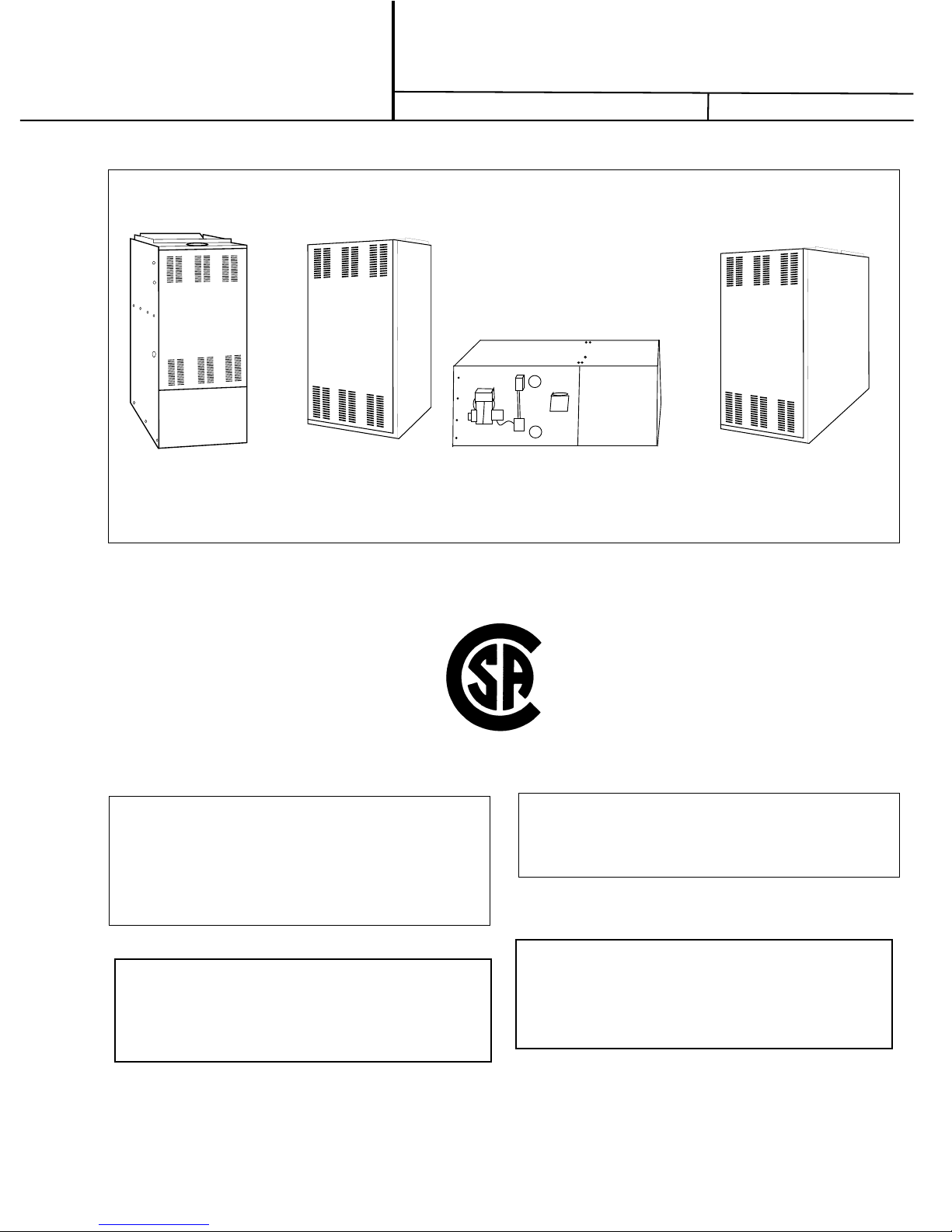
Coleman P*HBX12F08001, P*HBX16F10001, P*LBX12F08001, P*LBX16F12001, P*LBX16F14501 Installation Instructions Manual
...Page 1
INSTALLATION
INSTRUCTION
OIL-FIRED
WARM AIR FURNACES
Supersedes: 035-14289-000-A-300
035-14289-000-A-1101
P*HB (UPFLOW)
P*DH (DOWNFLOW
HORIZONTAL)
NRTL/C
CAUTION
THIS PRODUCT MUST BE INSTALLED IN STRICT COM
PLIANCE WITH THE ENCLOSED INSTALLATION IN
STRUCTIONS AND ANY APPLICABLE LOCAL, STATE,
AND NATIONAL CODES INCLUDING BUT NOT LIM
ITED TO, BUILDING, ELECTRICAL AND ME
CHANICAL CODES.
P*LB LOWBOY
WARNING
-
-
-
-
IMPROPERINSTALLATIONMAYCREATEACONDITION
WHERE THE OPERATION OF THE PRODUCT COULD
CAUSE PERSONAL INJURY OR PROPERTY DAMAGE.
FOR YOUR SAFETY
Do not store or use gasoline or other flammable
vapors and liquids in the vicinity of this or any
other appliance
.
WARNING: Improper installation, adjustment, al
teration, service or maintenance can cause injury
or property damage. Refer to this manual. For as
sistance or additional information,consult a quali
fied installer , service agency or the oil supplier.
-
-
-
Page 2
035-14289-000 Rev. A(0701)
TABLE OF CONTENTS
Introduction
Heat Loss
Unit Location/Clearances
Air Conditioning Applications
Combustion Air
................................................................
..................................................................
..........................................
................................
..........................................................
Downflow/Horizonal Applications
Chimney Venting
.......................................................
Unit Dimensions & Physical Data
Barometric Damper
Fan / Limit Control
Electrical Connections
Fuel Oil Piping
Oil Filter
.....................................................................
Oil Burner Nozzles
Oil Burner Adjustment
Oil Burner Electrodes
Oil Burner Primary Control
Air Blower
..................................................................
Maintenance/Service
Operating Instructions
Oil Burner Air Adjustment
Start Up
...................................................................
Sequence of Operation
Check Out
...............................................................
...................................................
.....................................................
...............................................
...........................................................
....................................................
...............................................
................................................
........................................
............................................
...............................................
..........................................
...........................................
..............................
.........................
2
2
2
2-3
3
3
3
4 - 5
6
6
7
7
8
8
8
8
8
8
9 - 9
9
9
10
10
10
IMPORTANT: SAVE THESE INSTRUCTIONS
FOR FUTURE REFERENCE
INTRODUCTION
Pleaseread these instructions completely and carefully before
installingand operating thefurnace. Please referto the dataon
pages 4 & 5 for performance and dimensional data.
In the United States the installation of the furnace and related
equipmentshall be installedin accordancewith the regulations
ofANSINFPANo. 31 (latestedition), Installation
Equipment, as well as in accordance with local codes.
In Canada, the installation of the furnace and related equipment shall be installed in accordance with the regulations of
CAN/CSA -- B139--M91 (latest edition), Installation
Oil Burning Equipment, as well as in accordance with local
codes.
Regulations prescribed in the National Codes and Local regu
lations takeprecedence over the general instructions provided
onthis installation manual. When in doubt,please consult your
local authorities.
All models are shipped assembled and pre--wired except model
P*LBX20F19001 where the blower section is separate. The
blower section is shipped together with the burner section, but
must be assembled together during installation. The furnace
shouldbecarefully inspectedfordamage whenbeingunpacked.
ofOilBurning
Code For
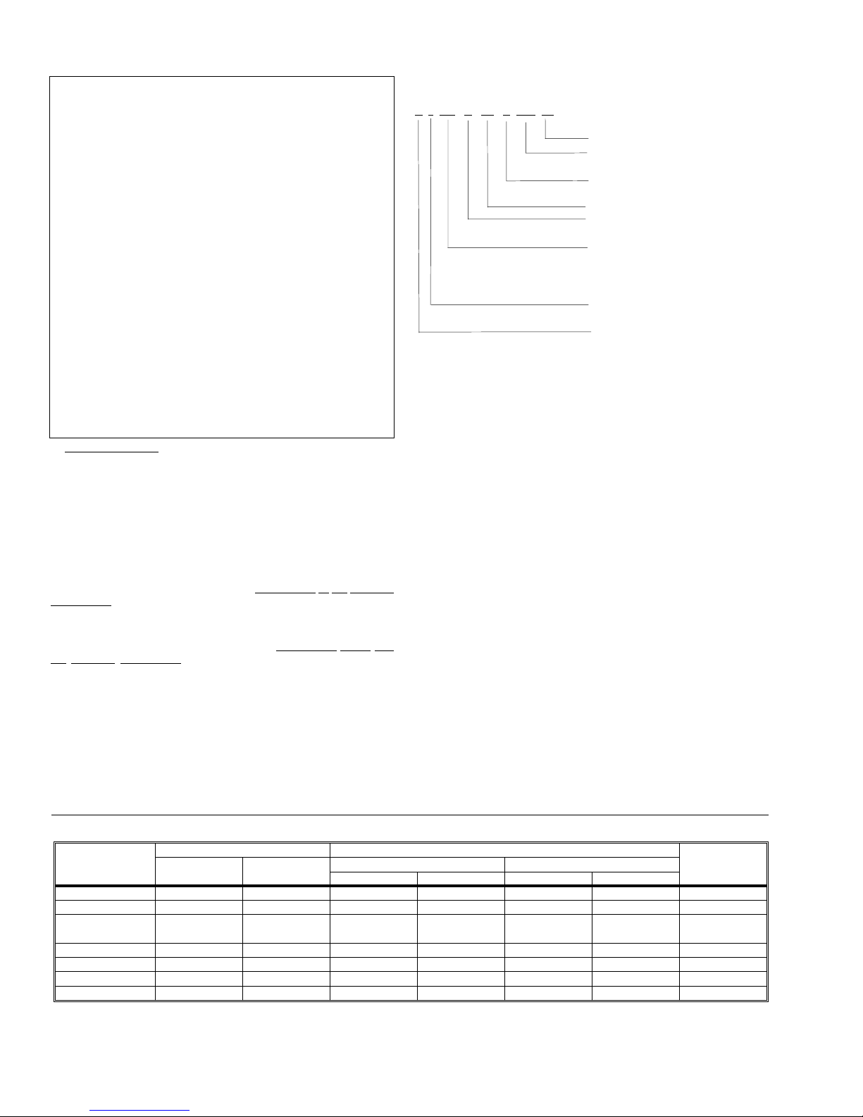
NOMENCLATURE
P * HB X 12 F 080 01
Voltage Code = 120 - 1 - 60
Nominal capacity
(MBH Output)
Heating Fuel
F = Fuel Oil
CFM (x100)
Cabinet
X = Non-Standard
Product Identifier
HB = Upflow,
DH = Downflow / Horizontal
LB = Lowboy
Product Generation
May be 1, 2, or 3
Product Category
P = Furnace
HEAT LOSS
The maximum hourly heat loss for each heated space shall be
calculated in accordance with the procedures described in the
following manuals.
In the United States ACCA Manual “J”. titled, “Load Calcula
tion”published by theAir Conditioning Contractors ofAmerica,
describes a suitable procedure for calculating the maximum
hourly heat loss.
InCanada, usethe Heating,Refrigeration andAir Conditioning
Institute of Canada (HRAI), or by any other method which is
suitable for local conditions, provided the results obtained are
insubstantial agreement with andnot less than thoseobtained
using the procedure described in the manual.
LOCATION OF UNIT
The furnace shouldbe located such that the flue connection to
the chimney is short, direct and consists of as few elbows as
possible.Whenpossible, theunit shouldbe centralizedwith re
spect to the supply and return air duct work. A central location
minimizes the trunk duct sizing. .
The minimum installation clearances are listed in Table 1.
-
-
-
TABLE 1 - CLEARANCES TO COMBUSTIBLES (INCHES)
CLEARANCE
FROM
TOP 1
FRONT 24
UPFLOW DOWNFLOW / HORIZONTAL
80 MBH 120 MBH
1
24
SIDES 111111
REAR 1
BOTTOM 0
1
0
S. A. PLENUM 1111131
FLUE PIPE 18* 18* 18* 18* 18* 18* 18*
NOTE: Adquate clearance should be provided over and above these clearances, as required for service access.
* May be 9 inches in Canada
** Elevated on 2-1/2 inch bricks
*** Front clearance required for servicing
2 Unitary Products Group
**** With floor base accessory
80 MBH 120 MBH
LOWBOY
DOWNFLOW HORZ. DOWNFLOW HORZ.
06033
6*** 24 16*** 24 24
Side 1 = 6
Side 2 = 18
111124
0**** 1 0**** 1 0**
Page 3
035-14289-000 Rev. A(0701)
AIR CONDITIONING APPLICATIONS
If the furnace is used in conjunction with air conditioning, the
furnace shall be installed in parallel with or upstream from the
evaporator coil to avoid condensation in the heat exchanger.
In a parallel installation, the dampers or air controlling means
must prevent chilled air from entering the furnace. If the damp
ersare manually operated, theremust be a meansof control to
prevent the operation of either system unless the dampers are
in the full heat or full cool position.
The air heated by the furnace shall not pass through a refrig
eration unit unless the unit is specifically approved for such
service.
The blower speed must be checked and adjusted to compen
satefor the pressure drop causedby the evaporator coil. Refer
toPage 12 for recommended wiring andelectrical connections
of the air conditioning controls.
COMBUSTION AIR
Ifthefurnaceisinstalled ina closetorutility room,two openings
must be provided connecting to a well ventilated space (full
basement,living room or other room opening thereto,but not a
bedroom or bathroom).
One openingshall be located above the level of the upper vent
opening and one opening below the combustion airinletopen
ing in the front of the furnace. Each opening shall have a mini
mum free area of 1
1
square inches per 1,000 Btu/h of total
2
input rating of all appliances installed in the room.
For furnaces located in buildings of unusually tight construc-
tion, such as those with high quality weather stripping, caulking, windows and doors, or storm sashed windows, or where
basement windows are well sealed, a permanent opening
communicating with a well ventilated attic or with the outdoors
shall be provided, using a duct if necessary.
1
The duct opening shall have a free area of 1
square inches
2
per 1,000 Btu/h of total input rating of all appliances to be installed. When a furnace is installed in a full basement, infiltra
tion is normally adequate to provide air for combustion and
draftoperation.Furnace roomsunder 700sq. ft.(65m
3
automatically be treated as confined space.
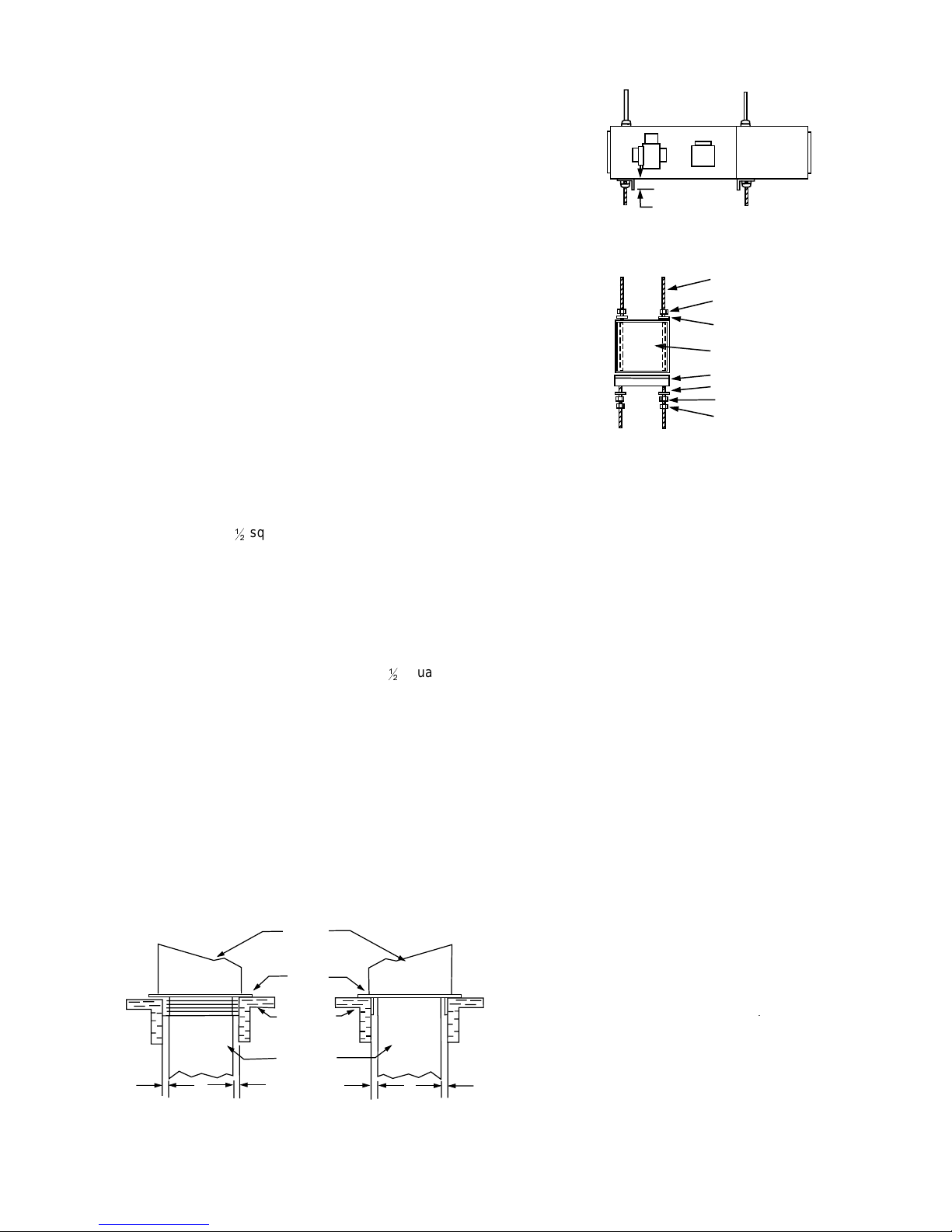
DOWNFLOW/HORIZONTAL FURNACES
Downflow/horizontal models (P*DHX12F08001 & P*
DHX16F12001) are factory shipped for downflow installation.
Downflow
Ifthe furnaceisto beinstalled ina downflowapplication,a com
bustible floor base must be used (either 1CB0312, or
1CB0316). Refer to Figure 1.
DOWNFLOW
FURNACE
SUB BASE
ASSEMBLY
COMBUSTIBLE
FLOOR
DUCT
CONNECTION
20-½ X 20-½
1 IN. 1 IN.
FRONT VIEW
FIGURE 1 - DOWNFLOW APPLICATION
COMBUSTIBLE FLOOR BASE
Unitary Products Group 3
1 IN.
SIDE VIEW
) should
1 IN.
-
2" MIN.
SIDE VIEW
-
THREADED ROD 3/8'
NUT
-
END VIEW
WASHER
FURNACE
SLOTTED ANGLE
WASHER
NUT
JAM NUT.
FIGURE 2 - HORIZONTAL SUSPENDED APPLICATION
-
HANGER ARRANGEMENT
-
Horizontal
For applying the furnace in a horizontal left or horizontal right
application follow these steps.
1. Rotate the furnace 90 degrees to the desired position.
2. Remove three nuts and washers fastening the oil burner
assemblyto thefurnace. Rotatethe oilburner assemblyto
an upright position (ignition transformer and/or protector
relay control should be on top).
3. Realign the oil burner assembly to the combustion cham-
-
ber(firepot) andthensecure withthreenuts andwashers.
4. Remove the cover from the flue collar.
5. Remove the screws securing the flue collar to the furnace
and then rotate the flue collar 90 degrees, such that the
venting attaches to the top.
6. Secure the flue collar to the furnace, then reinstall the flue
collar cover.
7. Horizontal-right applications using model P*DHX12F080
-
alsorequirerelocating thelimit controlto thealternative lo
cation near the top of the unit (refer to Figure 2).
For non-suspended horizontal applications, maintain clear
ances as shown on Table 1. Installation on a combustible floor
requires a clearance of 1". This can be done by using non-combustibles such as 1" channel iron or similar material. The
furnacemust be supported in such a wayto prevent twisting or
sagging of the cabinet.
For suspended horizontal applications maintain clearance as
shown in Table 3. Remove the four circular knockouts on the
top panel and the four knockouts on the bottom panel.
The removedknockoutsallow 3/8" threaded rod to be inserted
through the interior of the furnace. Refer to Figure 2.
Use care when inserting rods since the foil backed insulation
can be easily ripped and torn. Secure the furnace with 2" mini
mum slotted angle or equilavent. The furnace must be sup
ported in such a way to prevent sagging or twisting of the
cabinet.
-
-
-
-
Page 4
035-14289-000 Rev. A(0701)
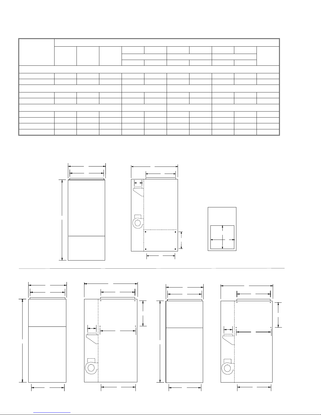
TABLE 2 - UNIT DIMENSIONS
MODEL
A
HEIGHTBWIDTH
C
DEPTH
WIDTH DEPTH WIDTH DEPTH HEIGHT DEPTH
DIMENSIONS - INCHES
DEFG
J
SUPPLYAIR BOTTOM RETURN SIDE RETURN
KH
FLUE
CONNECT .
UPFLOW
P*HBX12F08001 49-5/8 22 31 20-1/2 20 14 22 14 22 5
P*HBX16F10001 58-1/4 22 30-3/4 20-1/2 20 14 22 14 22 6
DOWNFLOW / HORIZONTAL SUPPLY AIR RETURN AIR
P*DHX12F08001 51 22 31-1/4 19 19 18 18 — — 5
P*DHX16F12001 62 22-1/4 22-1/4 20-1/2 20-1/2 18 18 — — 6
LOWBOY SUPPLYAIR RETURN AIR
P*LBX12F08001 31 22 43 20-1/2 18-5/8 20-1/2 18-5/8 — — 5 (REAR)
P*LBX16F12001 41 22 52-1/2 20-1/2 18-5/8 20-1/2 18-5/8 — — 6 (REAR)
P*LBX16F14501 41 22 52-1/2 20-1/2 18-5/8 20-1/2 18-5/8 — — 6 (REAR)
P*LBX20F19001 56 26 49 24 22 24 22 — — 7 (REAR)
UPFLOW - MODELS P*HB
*
,
C
E
H
)
DOWNFLOW/HORIZONTAL - MODEL P*DH16F12001
(Exposed burner)
*
,
0
)
+
-
,
G
J
K
BOTTOM VIEW
F
DOWNFLOW/HORIZONTAL- MODEL P*DH12F08001
*
,
-
0
)
+
-
-
,
/
4 Unitary Products Group
.
/
.
Page 5
035-14289-000 Rev. A(0701)
PHYSICAL & ELECTRICAL DATA
PUT
1
OIL
RATE
GPH
-
AFUE
%
2
CFM @
.5 IWG
E.S.P.
3
UNIT
AMPS
MAX.
OVERCURRENT
PROTECT.
WIRE
SIZE
AWG
BLOWER
SIZE HP TONS NOM.
FILTERS
QTY. &
SIZE
MODEL
HEATINGMBH
INPUT * OUT
UPFLOW
P*HBX12F08001 91 80 .65 82.0 1291 12.0 15 14 10 x 10 1/2 (1) 16 x 25 2, 2P*HBX16F10001 119 100 .85 82.7 1445 12.0 15 14 10 x 10 1/2 (1) 16 x 25 3, 3-
DOWNFLOW / HORIZONTAL
P*DHX12F08001 91 80 .65 82.0 1291 12.0 15 14 11x 10 1/2 (1) 120x 20 2, 2P*DHX16F12001 140 120 1.0 80.1 1593 12.0 15 14 11 x 10 1/2 (1) 20 x 20 3, 3-
LOWBOY
P*LBX12F08001 91 80 .65 85.1 1717 12.0 15 14 12 x 9 1/2 (1) 20 x 20 2, 2P*LBX16F12001 140 120 1.0 83.4 1585 12.0 15 14 12 x12 1/2 (1) 20 x 25 3, 3P*LBX16F14501 168 145 1.20 83.5 1585 12.0 15 14 12 x 12 1/2 (1) 20 x 25 3, 3P*LBX20F19001
* Standard input as shipped. See Table 3, Page 8 for alternate firing rates.
1
For Altitudes above 2000 feet, reduce ratings 4% for each 1000 feet above sea level.
2
AFUE (Annual Fuel Utilization Efficiency) determined using DOE test procedure, isolated combustion.
3
Available external static pressure is at furnace outlet and ahead of cooling unit.
231 190 1.65 78.0 2135 12.0 15 14 12 x 12 3/4 (2) 20 x 25
LOWBOY - MODELS P*LBX16F12001, P*LBX16F14501, P*LBX16F19001
ADD-ON
COOLING
1
, 3 1200
2
1
, 4 1600
2
1
, 3 1200
2
1
, 4 1600
2
1
,3, 3-
2
1
, 4 1600
2
1
, 4 1600
2
1
3-
, 4, 5
2
1
,4 1200
2
CFM
2000
*
,
)
LOWBOY - MODEL P*LBX12F08001 (Exposed Burner)
B
D
E
2-½
F
H
A
Unitary Products Group 5
8-1/2
C
Page 6

035-14289-000 Rev. A(0701)
W
FAN & LIMIT LOCATION
LEFT HORIZONTAL APPLICATION
FAN & LIMIT LOCATION
AIR FLO
BAROMETRIC DAMPER CONTROL
Thisdevice mustbe usedwith allchimney andTypeLvent sys
tems.This control(or draftregulator) automaticallymaintains a
constant negative pressure in the furnace to obtain maximum
efficiency.Itensuresthatproper pressuresarenot exceeded.
If the chimney does not develop sufficient draft, the draft control
cannot function properly. The draft regulator, when installed
should be in the same room or enclosure as the furnace and
should not interfere with the combustion air supplied to the
burner.
The control should also be located near the furnace flue outlet
and installed according to the instructions supplied with the
regulator.The flue outletpressure (measured between the fur
nace and draft regulator) should be set to --0.02 in. w.c.
-
-
AIR FLOW
FAN AND LIMIT CONTROL
Upflow & Lowboy Models
The L6064A temperature sensitive fan switch is actuated by a
helical bi--metal sensing element enclosed in a metal guard,
and controls the circulating air blower. This provides a delay
betweenthe burnerignition andblowerstartupto eliminateex
FIGURE 3 - HORIZONTAL APPLICATION
RIGHT HORIZONTAL APPLICATION
FAN/LIMITLOCATION
CAUTION: Fan/limit control location is critical in the
P*DHX12F08001 horizontal positions. Tooperate effectively as a high limit control, the fan / limit control
mustbeinstalled intheupper position.SeeFigure 3.
CHIMNEY VENTING
The flue pipe should be as short as possible with horizontal
pipessloping upward towardthe chimney ata rate of onequarter inchtothe foot. The flue pipe should not be smaller in cross
sectional area than the flue collar on the furnace.
The flue pipe should connect to the chimney such that the flue
pipe extends into, and terminates flush with the inside surface
ofthe chimney liner.Sealthe joint betweenthe pipe andthe lin
ing.
The chimney outlet should be at least two feet above the high
estpointofapeaked roof.All unusedchimney openingsshould
be closed.
Chimneysmust conformtolocal, provincialor statecodes, orin
the absence of local regulations, to the requirements of NFPA
2.11(latest edition) Chimney,Fireplaces, Ventsand Solid Fuel
Burning Appliances (in Canada CSA B139)..
NOTE: All furnace models are approved for use with
Type Lvent or equivalent.
CAUTION: The furnace must be connected to a flue
having sufficient draft at all times to ensure safe and
proper operation of the appliance.
NOTE: The recommended flue draft pressure is --
0.02in. W.C. (asmeasured upstream of the baromet
ric draft regulator).
The flue pipe must not pass through any floor or ceiling, but
may pass through a wall where suitable fire protection provi
sions have been installed. Refer to the latest edition of ANSI
NFPA31(in theUnited States,or CAN/CSAB--139 in Canada)
for regulations governing the installation of oil burning equip
ment.
See Table 4 for burner set-up.
cessive flow of cold air when the blower comes on. Blower
shutdownis also delayed toremove any residual heatfrom the
heat exchanger and improve the annual efficiency of the fur
nace. Fan settings of 120° Fto130°F (50° Cto55° C) and fan
settingsof 90° F to 100°F (32° Cto37°C) will usually be satis-
factory.
Downflow /Horizontal Models
The L4064W temperature sensitive fan switch contains a
heater--wrapped bi--metal to actuate the fan switch independentof the temperature atthe helical sensing element.The time
fromignition, tothe bloweron functionis approximately30 seconds. If after 1 minute, the blower has not come on, replacementof the control may be necessary.The blowershutdown is
the same as noted for the L6064A control.
Thelimit switchperforms asafety functionandbreaks powerto
the oil burner primary control, which shuts off the burner if the
furnaceover--heats.The limitcontrol isthermally operatedand
automatically resets. The limit control is factory installed, pre--
-
set and is not adjustable.
The limit control and fan control are incorporated in the same
housing and are operated by the same thermal element.
The downflow furnace utilizes an additional auxiliary limit con
trol which is an automatic reset type.
ELECTRICAL CONNECTIONS
The furnace is listed by the Canadian Standards Association
under the NRTL (North American) Standard. It is factory wired
and requires minimal field wiring. All field wiring should con
form to the following standards or by local codes, where they
prevail and by In the United States, refer to the National Fire
Protection Association NFPA--70, National Electrical Code
-
(latestedition), or in Canada, CAN/CSAC22.1Canadian Elec
trical Code, Part 1, and with local codes and regulations.
The furnace should be wired to a separate and dedicated cir
cuit in the main electrical panel; however, accessory equip
ment such as electronic air cleaners and humidifiers may be
included on the furnace circuit. Although a suitably located cir
cuit breaker can be used as a service switch, a separate serv
ice switch is advisable. The service switch is necessary if
reachingthe circuit breakerinvolves becoming closeto the fur
nace, or if the furnace is located between the circuit breaker
and the means of entry to the furnace room.
6 Unitary Products Group
-
-
-
-
-
-
-
-
-
-
Page 7

035-14289-000 Rev. A(0701)
The furnace switch (service switch) should be clearly marked,
installed in an easily accessible area between the furnace and
TABLE 3 - OIL PIPING LENGTHS (FEET)
furnaceroom entry,and be located in sucha manner to reduce
thelikelihood that it wouldbe mistaken asa light switch orsimi
lar device.
Accessories requiring 120 VAC power sources such as elec
tronic air cleaners and humidifier transformers may be pow
ered from the furnace circuit, but should have their own
controls
Do not use the direct drive motor connections as a power
source, since there is a high risk of damaging the accessories
by exposure to high voltage from the auto--generating wind
ings of the direct drive motor.
Thermostat wiring connections and air conditioning contactor
low voltage connections are shown in the wiring diagrams on
Page 12. Some micro--electronic thermostats require addi
tional controls and wiring. Refer to the thermostat manufac
turer's instructions.
CAUTION: A room thermostat with independent
heat/cool circuit is required.
The thermostat should be located approximately 5 feet above
thefloor, onan inside wall where there isgood natural air circu
lation,and where thethermostat will beexposed to averageroom
temperatures. Avoid locations where the thermostat will be ex
posed to cold drafts,heat from nearby lamps and appliances, ex
posure to sunlight, heat from inside wall stacks, etc.
NOTE: Some electronic thermostats do not have adjustable heat anticipators. They may have other type
cycle rate adjustments. Follow the thermostat manufacturer's instructions.
-
-
-
LIFT
1 53 100 68 100
SINGLE STAGE 2-STAGE
3/8" O.D.
TUBING
1/2" O.D.
TUBING
3/8" O.D.
TUBING
2 49 100 65 100
3 45 100 63 100
4 41 100 60 100
5 37 100 58 100
-
6 33 100 55 100
7 29 100 53 100
8 259950100
9 218348100
-
-
10 17 68 45 100
12 13 52 42 100
12 — — 37 100
14 — — 32 100
16
18
— — 27 100
— — 22 88
component in the line. In general, keep single line systems
-
short as possible. If the furnace is to be installed in a sus
-
pendedposition,a twopipesystem maybea betteralternative.
Two--stage oil pumps may be used with both single line and
two line systems. Two--stage pumps are available from your
HVACwholesaler.Table 3lists allowable line lengths (horizontal plus vertical) for single and two stage oil pumps.
1/2" O.D.
TUBING
In retrofit applications where an existing oil line system is in
Set the heat anticipator in the room thermostat to .4
amps. for models P*HBX12F080, P*DHX12F080 &
P*DHX16F120; for other models set heat anticipator at
.2 amps. Setting it lower will cause short cycles. Setting
it higher will cause the room temperature to exceed the
setpoint.
place, a vacuum check will help determine if a two--stage oil
pump is necessary. The vacuum in a system using a single
stageoil pump should not exceed 6" Hg. The vacuum in a systemusing a two--stageoil pumpshould not exceed15" Hg. For
additionalinformation,refertothe instructioninformation sheet
affixed to the oil burner.
Installthe oilfilter asclose tothe burneras possible.For further
HUMIDIFIER
A humidifier is an optional accessory available through most
heating supplies outlets. Installation should be carried out in
accordance with the humidifier manufacturer's installation in
structions. Water or water droplets from the humidifier should
not be allowed to come into contact with the furnace heat ex
changer.Donotuse direct drivemotor connectionsas asource
ofpowerfor 120VAChumidifiersandhumidifier transformers.
details of the oil supply tank and piping requirements, please
referto the instructions and illustrationsin the oil burnerand oil
pump instructions shipped with the furnace.
-
OIL FILTER
All fuel systems should include an oil filter between the fuel oil
storage tank and the oil burner.When using an oil burner noz
zle smaller than 0.65 U.S. Gallons Per Hour, install an addi
tional7to 10micronfilter ascloseas possibleto theoilburner.
PIPING INSTALLATION
The entire fuel system should be installed in accordance with
the requirements of ANSI NFPANo. 31 in the United States or
CAN/CSA B--139 in Canada, and local regulations. Use only
an approved fuel oil tanks piping, fittings and oil filter.
Ensure that all fittings used in a copper oil line system are high
quality flare fittings. Do
not use compression fittings.
Pressurized or gravity feed installations must not exceed 10
PSIG ontheinlet line or the return line at the pump. Apressure
greater then 10 PSIG may cause damage to the shaft seal.
The furnace may be installed with a one pipe system or gravity
feedorlift. Themaximumallowable liftona singlelinesystem is
8ft. Liftshouldbe measuredfromthe bottom(outlet) ofthe tank
to the inlet of the burner.
Sizing a single line system is complex because of the difficulty
estimating the pressure drop through each fitting, bend and
Unitary Products Group 7
OIL BURNER NOZZLES
These furnaces are certified for multiple firing rates, ranging
from60,000to 181,000Btu/h dependingon model.Bymanipu
lating the oil burner nozzle, flame retention head, static plate
and temperature rise, the furnace may be fired at an ideal rate
fora widerange of structures.Refer toTable4,and thefurnace
rating plate to determine the proper combinations.
CAUTION: Before operating the furnace check
burner alignment with the combustion chamber. The
end cone of the air tube must be centered to the ac
commodating ring provided in the design of the com
bustion chamber. Adjust as necessary.
-
-
-
-
-
-
Page 8

035-14289-000 Rev. A(0701)
TABLE 4 - BECKETT AF OIL BURNER SET-UP
MODEL
P*HBX12F08001
P*HBX16F10001
P*LBX12F08001
P*LBX16F12001
P*LBX16F14501
P*LBX20F19001
P*DHX12F0801
OUTPUT
(BTU/H)
BURNER
MODEL
NOZZLE
PUMP
PRESSURE
FLOW RATE HEAD
STATIC
PLATE
UPFLOW
60,000 AF76BO
78,000 AF76BO
90,000 AF76XN
0.50 / 60° A
0.65 / 60° A
0.75 / 60° A
100 PSIG 0.50 GPH F0 3-3/8"
100 PSIG 0.65 GPH F0 3-3/8"
100 PSIG 0.75 GPH F3 2-3/4"
100,000 AF76XN 0.85 / 60° A 100 PSIG 0.85 GPH F3 2-3/4"
79,000 AF65XN
90,000 AF65XN
101,000 AF65XN
119,000 AF65XN
0.65 / 80° A
0.75 / 80° A
0.85 / 80° A
1.00 / 80° A
100 PSIG 0.65 GPH F3 2-3/4"
100 PSIG 0.75 GPH F3 2-3/4"
100 PSIG 0.85 GPH F3 2-3/4"
100 PSIG 1.00 GPH F3 2-3/4"
LOWBOY
60,000 AF63B0PWHS
78,000- AF63B0PWHS
90,000
AF63XNPWH
S
79,000 AF76XN
90,000 AF76XN
101,000 AF76XN
117,000 AF76XN
130,000 AF76YB
143,000 AF76YB
168,000 AF65XO
181,000 AF65XO
0.50 / 60° A
0.50 / 60° A
0.75 / 60° A
0.65 / 80° A
0.75 / 80° A
0.85 / 80° A
1.00 / 80° A
1.10 / 70° A
1.20 / 60° A
1.50 / 70° B
1.65 / 70° B
100 PSIG 0.50 GPH F0 3-3/8"
100 PSIG 0.65 GPH F0 3-3/8"
100 PSIG 0.75 GPH F3 2-3/4"
100 PSIG 0.65 GPH F3 2-3/4"
100 PSIG 0.75 GPH F3 2-3/4"
100 PSIG 0.85 GPH F3 2-3/4"
100 PSIG 1.00 GPH F3 2-3/4"
100 PSIG 1.10 GPH F6 2-3/4"
100 PSIG 1.20 GPH F6 2-3/4"
100 PSIG 1.50 GPH F12 2-3/4"
100 PSIG 1.65 GPH F12 2-3/4"
DOWNFLOW/HORIZONTAL
60,000 AF76BO
78,000 AF76BO
90,000 AF76XN
0.50 / 60° A
0.65 / 60° A
0.75 / 60° A
100 PSIG 0.50 GPH F0 3-3/8"
100 PSIG 0.65 GPH F0 3-3/8"
100 PSIG 0.75 GPH F3 2-3/4"
BURNER PRIMARY (SAFETY) CONTROL
The furnace is equipped with a primary combustion control,
sometimes referred to as the burner relay or burner protector
relay,whichuses alight sensing device(cad cell) locatedin the
burner housing, to monitor and control combustion.
Over time, dust or combustion residuals can build up on the
lens of the cad cell impairing its response to the flame. The
cad cell should be checked for cleanliness and proper align
ment if the primary control frequently shuts down combus
tion.
CIRCULATING AIR BLOWER
These furnaces (with the exception of model P*LBX20F190
which is belt drive) are equipped with direct drive blower sys
tems. Direct drive blower speed adjustments are not normally
requiredin properly sized extended plenumduct systems. The
motor RPM and air CFM delivery will vary automatically to ac
commodateconditions within the usual rangeof external static
pressures typical of residential duct systems.
-
-
Under-sized duct systems may require a higher blower speed
to obtain a reasonable system temperature rise. Some older
duct systems were not designed to provide static pressure.
COMBUSTION CHAMBER
This furnace is equipped with a high quality cerafelt combus
tion chamber. It is held in place by a retaining bracket.
CHECK THE ALIGNMENT OF THE COMBUSTION CHAM
BER AND OIL BURNER BEFORE FIRING. IT IS POSSIBLE
FOR THE COMBUSTION CHAMBER TO SHIFT IF SUB
JECTED TO ROUGH HANDLING DURING TRANSIT.
The combustion chamber should be inspected for damage or
carbon build up whenever the oil burner is removed for repairs
or routine maintenance.
WARNING:Do not start the burner unless the blower
access door is secured in place.
They typically feature special reducing fittings at each branch
run and lack block ends on the trunk ducts.
These systems may require modification to provide some re
sistance to the airflow to prevent over-- amping of the direct
-
drive blower motor. Selecting a lower blower speed may cor
rect this problem.
Direct drive blower speeds are adjusted by changing the “hot”
wires to the motor winding connections. Please refer to wiring
diagram on Page 12, or the wiring diagram label affixed to the
furnace. THE NEUTRAL WIRE (normally the white wire) IS
NEVER MOVED TO ADJUST THE BLOWER SPEED.
It is possible and acceptable to use a single blower speed for
both heating and cooling modes. The simplest method to con
nect the wiring from both modes is to use a “piggy--back con
nector” accommodating both wires on a single motor tap.
8 Unitary Products Group
-
-
-
-
-
-
Page 9

035-14289-000 Rev. A(0701)
Itis alsoacceptable toconnect the selectedmotor speedwith a
pig tail joined to both heating and cooling speed wires with a
wire nut. As a safety precaution against accidental disconnec
tion of the wires by vibration, it is advisable to secure the wire
nut and wires with a few wraps of electricians tape.
CAUTION:Do not connectpower leads between mo
tor speeds. The neutral wire must always be con
nected to the motor's designated neutral terminal.
WARNING: Disconnect the power supply to the fur
nace before opening the blower access door to serv
ice the air filter,fan or motor. Failure to shut off power
could allow the blower to start unexpectedly,creating
a risk of death or personal injury.
If the joining of the blower speed wiring is done in the furnace
junction box, tape off both ends of the unused wire.
Do not use the blower speed wires as a source of power to
accessories as electronic air cleaners and humidifier
transformersunless
will be used. The unused motor taps auto--generate suffi
ciently high voltages to damage accessory equipment.
itis certainthatonly one motor speed
MAINTENANCE AND SERVICE
Routine Maintenance By Home Owner
Otherthan rememberingto arrangefor theannual professional
servicingof thefurnace bythe serviceor installationcontractor,
the most important routine service performed by the home
owneris tomaintain theair filteror filters.Adirty filtercan cause
the furnace to over--heat, fail to maintain indoor temperature
during cold weather, increase fuel consumption and cause
component failure.
The furnace filter(s) should be inspected, cleaned or replaced
monthly. The furnace is factory equipped with a semi-permanenttype filter.Ifthe filteris damaged,replace withfilters
of the same size and type. (See Page 5 for listing).
During the routine service, inspect the general condition of the
furnace watching for signs of oil leaks in the vicinity of the oil
burner, soot forming on any external part of the furnace, soot
forming around the joints in the vent pipe, etc. If any of these
conditions are present, please advice your service or installa
tion contractor.
Annual Service By Contractor
CAUTION: The combustion chamber (firepot)is frag
ile.Usecare wheninspectingand cleaningthisarea.
The heat exchanger should be inspected periodically and
cleaned if necessary. if cleaning is necessary, SHUT OFF
POWER TO THE FURNACE and remove the burner. Using a
stiff brush with a wire handle, brush off scale and soot from in
side the drum and flue pipe. Toclean the radiator, remove the
round covers on the inner front panel to gain access to the
cleaning ports.
When this procedure is done for the first time, carefully cut
away the insulation covering the opening with a sharp knife.
Loosen the nuts on the radiator clean--outs. DO NOT RE
MOVE THE NUTS. Remove the covers carefully to avoid tear
ing the gaskets. A wire brush can be used to loosen dirt and
debris on the inside surfaces of the radiator.
Cleanout all accumulated dirt, sootanddebris with a wire han
dled brush and an industrial vacuum cleaner.Before replacing
the clean--out covers, inspect the gaskets. If the gaskets are
broken, remove the remnants and replace with new gaskets.
Snug the cleanout covers. DO NOT OVER--TORQUE THE
Unitary Products Group 9
CLEAN--OUT NUTS. Replace the inner front panel clean--out
covers.
-
NOTE: A radiator clean--out assembly inadvertently
droppedinto the interior of thefurnace can usually be
-
-
Thedirect driveblower motoris factoryoiled. Undernormal op
-
erating conditions it does not require oiling for the first two
-
years. Oil sparingly (a few drops) in each oil port with SAE 20
non--detergent oil. Oiling is most easily done with a “tele-spout” oilier. This oiler has a long flexible plastic spout. DO
NOT OVER--LUBRICATE.Excess oil causes premature elec
tric motor failure.
Inspect the blower fan. Clean if necessary.
Oil Burner Maintenance: Follow the instructions of the oil
burner manufacturer. (See oil burner manufacturer's instruc
-
tions supplied with furnace). It is advisable to change the oil
burner nozzle and oil filter on an annual basis.
Theventing systemshould becleaned and inspectedfor signs
of deterioration. Replace pitted or perforated vent pipe and fit
tings. The barometric damper should open and close freely.
All electrical connections should be checked to ensure tight
connections. Safety controls such as the high limit controls
should be tested for functionality. The fan control should be
checked to ensure that the “fan off” function continues to stop
the blower fan at temperatures between 90° F to 100° F.
easily retrieved with a magnet on a wire handle or
stout string.
OPERATING INSTRUCTIONS
Before Lighting
1. Open all supply and return air registers and grilles.
2. Open all valves in oil pipes.
3. Turn on electric power supply
To Light Unit
1. Set the thermostat above room temperature to call for
-
-
-
-
-
-
heat.The burner should start.NOTE: It maybe necessary
to press the RESET button on the primary combustion
control relay.
2. After ashort period of time, as thefurnace becomes warm
enoughthe act uponthe fan control(L6064A), or preheats
the bi--metallic element (L4064W), the blower should
start.
3. Set the thermostat below room temperature. The oil
burner should stop.
4. Theair circulationblowerwill continueto runaslong asthe
temperature in the furnace is higher than the “FAN OFF”
setting on the fan control. Typical “fan on” values range
from120° Fto 130° F.Typical“fan off”temperatures range
between 90° F and 100° F. The fan control adjustments
may be altered if the air at the room registers is uncom
fortably high upon blower start up or shutdown, the fan
control settings can be lowered.
5. The adjustments to the fan control settings should be
made by measuring the temperature of the air in the sup
ply air take--off, or within the first few inches of the supply
air trunk. The side mid point of the transition is usually
ideal, providing that the thermometer probe is beyond the
“line of sight” wherein false readings from radiant heat
could be observed. The system temperature rise, the dif
ference in temperature between the supply air and return
air, will typically range between 65° F and 70° F.
-
-
-
-
-
-
-
Page 10

035-14289-000 Rev. A(0701)
Tocheck the operation of the limit switch, shut off power to the
furnace. Temporarily remove the neutral wire from the direct
drive blower motor.Restore the electrical power to the furnace
and set the thermostatabove room temperature. After three or
four minutes of burner operation, the limit control should turn
the burner off.
The progress towards a high limit shut down can be monitored
by watching the dial on the fan / limit control. When the limit
function test is complete, shut off electrical power to the fur
nace, replace the neutral wire to the blower fan motor,then re
storepower. Theblower fan will start upimmediately.Once the
temperature has dropped, the oil burner will resume and con
tinue until the thermostat is satisfied. Restore the thermostat
setting to a comfortable temperature.
To Shut Down Unit
1. Set the thermostat to the lowest possible setting.
2. Set the manual switch (if installed) in the Electrical Power
Supply Line to “OFF”.
NOTE: If the furnace is to be shut down for an ex
tendedperiod of time, close theoil supply valve to the
burner.
OIL BURNER AIR ADJUSTMENT
For complete details, consult the oil burner instruction manual
provided in the furnace documents envelope.
Beckett AF Burner
Adjustthe airshutter by looseningthe lockingscrews and mov-
ing the air shutter, and if necessary, the bulk air band.
Procedure
Startthe burner and allow it to run at least ten minutes. Set the
air shutter to give a good flame visually. The air supply to the
burner is controlled by the air shutter on the left side of the
burner,and the bulk air band. To adjust, loosen the bolt on the
movableshutter. Move theshutter gradually until a good flame
(visually) has been achieved. Re--snug the bolt.
Check the initial draft setting as the furnace warms up. The
draftmaybe measuredat thetest port.In mostcases, thepres
-
sure dropbetween the test port and the oil burner is negligible.
-
The test port draft reading may be interpreted as the “over fire
draft” reading. The draft should be set to -- 0.02 inches w.c.
Check the oil pump pressure. All furnaces are designed to be
operated at 100 psig.
After reaching steady state,take a smoke test. If not indicating
a trace, set the combustion air controls to provide a trace. In
-
-
BURNER ELECTRODES
Adjustment of the electrode tipswith respect to each other, the
nozzle,andto the rest of the burner is very importantto ensure
smooth start ups and to permit efficient combustion.
Beckett AF Burner Settings
•
Electrode gap: 5/32 inch.
•
Distance above horizontal centerline: 7/16 inch.
•
Distance ahead of nozzle: 1/16 inch.
Thedistancefrom thefront ofthe endcone (head)to theface of
the nozzle should be 1--1/8 inches. If a ceramic head is used,
the distance from the end cone to the nozzle face is increased
to 1--3/8 inches.
OIL BURNER SET UP
Theburner air supply is adjustedto maintain the fuelto air ratio
toobtainideal combustionconditions. Alackofair causes“soft”
and “sooty” flames, resulting in soot build--up throughout the
heat exchanger passages. Excess combustion air causes a
brightroaring fire andhigh stacktemperatures resulting inpoor
fuel efficiency.
Preparations
Drill a 1/4" test port in the venting, ideally at least 2 diameters
(12") away from the furnace breaching. If venting horizontally
fromthe furnace,or fromthe flue pipeelbow ifventing vertically
before reaching the furnace (refer to Figure 4).
Before startingthe burner, checkthe burner alignment with the
combustion chamber (firepot), check that the correct nozzle is
tightened into place, and that the burner electrodes are prop
erly positioned.
10 Unitary Products Group
FIGURE 4 - TEST LOCATIONS FOR SMOKE TEST
(TOP - HORIZONTALINSTALLATION)
(BOTTOM - VERTICAL INSTALLATION)
NOTEA:Locateholeatleast6inchesonthe furnace side of the draftcontrol.
-
NOTE B: Ideally, hole should be at least 12 inches from breeching or elbow.
The test port will allow flue gas samples to be taken and stack temperature
to be measured.
Page 11

most cases, adjustment of the end air shutter will be all that is
necessary.
035-14289-000 Rev. A(0701)
ducts. Typical temperature rise values range between 65° F
and 90° F.
When the trace smoke has been established, measure the
orO2inthe flue gas. Typically,the CO2readingwill be ap
CO
2
proximately 13% or the O
reading approximately 3.3%.
2
Open the end air shutter (or open the bulk air band if neces
sary)until the CO
measuring O
readingdrops 1or 2 percentagepoints, or,if
2
content, until the O2reading increases 2 or 3
2
percentage points.
Take another smoke test; it should now be zero smoke. If the
smoke test reads zero, tighten up the end air shutter, and the
bulk air band.
Re--test the draft and the CO
or O2to be certain that the set
2
tings have not shifted.
NOTE: If oily or yellow smoke sports arefound on the
smoketest filter paper,it is usuallya sign of unburned
fuel. This indicates poor combustion. This type of
problem may be caused by excess draft, excess air,
or contaminated fuel. Do not ignore this indicator.
Stack Temperature
Stacktemperaturewill vary depending onfuel input, circulating
air blower speed and burner set up, etc. In general, stack tem
perature should range between 350° Fto450° F,but could be
as high as 550° F, assuming that the combustion air approxi
mately room temperature (65° F--70° F). In general, lower
stack temperature indicates greater efficiency; however, excessive low stack temperature can lead to condensation forming in the chimney and/or venting. Sulfur and similar
contaminants in the fuel oil will mix with condensation to form
acids. Acids andresultant chemical salts will cause rapid deterioration of the chimney and venting components, and may attack the furnace.
If the flue gases are below the range, it may be necessary to
slowdownthe blowerfan. Iftheflue gasesareabove therange,
the blower may require speeding up. Stacktemperature varies
directly with the system temperature rise. System temperature
rise is the difference between the furnace outlet temperature
andthe furnace inlettemperature as measuredin the vicinityof
the connection between the plenum take--offs and the trunk
If the venting from the furnace to the chimney is long or ex
-
posed to cold ambient temperatures, it is advisable to insulate
theventing with aremovable, non--combustible, wrap--around
type insulation to reduce stack temperature loss. The vent
should be inspected annually to ensure that it is intact.
FINAL CHECK OUT
Before the final test cycle, carefully examine the complete
heatingsystem forleaks. The hotvent canbe checkedwith a lit
taper for signs of air movement around joints or seams.
Ensure that all safety devices and electrical components have
been set for normal operation. Ensure that all electrical con
nections are tight and that the wiring is secure.
IMPORTANT:
Please review the following items with the homeowner:
where the circuit breaker or fuse is located in the main
•
electrical panel.
-
-
where the furnace switch is located, and the switch “on”
•
and “off” positions if not obvious.
where the oil shut--off valve from the oil storage tank is
•
located.
• how to operate the thermostat, and other related accessories.
• how to operate the manual reset button on the primary
control,andespecially whennotto pushthereset button.
• how and where to visuallyinspect the venting system for
leaks or other problems.
• how to inspect, clean and replace the air filter, and other
homeowner maintenance procedures.
•
who to call for emergency service and routine annual
service.
•
the terms and conditions of the manufacturer's warranty
and the contractor's warranty.
-
-
Unitary Products Group 11
Page 12

035-14289-000 Rev. A(0701)
BLOWER PERFORMANCE
MODEL SPEED
P*HBX12F08001
P*DHX12F08001
P*HBX16F10001
P*DHX16F12001
P*LBX12F08001
P*LBX16F12001
P*LBX16F14501
P*LBX20F19001
TAP
HIGH 1505 1444 1359 1291 1195
MED HIGH 1423 1381 1291 1220 1144
MED LOW 1170 1144 1118 1063 1005
LOW 813 813 797 763 690
HIGH 1645 1575 1510 1445 1337
MED HIGH 1540 1500 1420 1350 1266
MED LOW 1145 1135 1115 1095 1035
LOW 745 745 725 715 646
HIGH 1752 1691 1659 1593 1525
MED HIGH 1454 1454 1417 1379 1300
MED LOW 975 944 912 879 844
LOW 631 593 552 515 486
HIGH 1917 1885 1820 1717 1608
MED HIGH 1590 1608 1590 1532 1430
MED LOW 1096 1096 1096 1068 1039
LOW 696 647 692 647 598
HIGH 1810 1740 1675 1585 1480
MED HIGH 1570 1540 1495 1445 1348
MED LOW 1090 1080 1070 1065 1036
LOW 710 700 690 665 614
TURNS OPEN
0 2707 2503 2303 2135 1898
1 2372 2233 2085 1870 1594
2 2257 2085 1841 1594 1216
3 2161 1926 1627 1259 795
0.20 0.30 0.40 0.50 0.60
NOTES:
Airlfow is expressed in standard cubic feet per minute.
Motor voltage at 115V
EXTERNAL STATIC PRESSURE, INCHES W.C.
12 Unitary Products Group
Page 13

WIRING DIAGRAM - ALL MODELS
035-14289-000 Rev. A(0701)
Unitary Products Group 13
Page 14

035-14289-000 Rev. A(0701)
SYSTEM TROUBLESHOOTING
PROBLEM POSSIBLE CAUSE REMEDY
Furnace will not start
Furnace will not start
without first pushing
protector relay reset
button
(Happens on a
frequent basis)
Furnace starts, but
cuts out requiring
manually resetting the
oil protector reset but
ton
Thermostat
not calling for heat
No power to furnace
Thermostat faulty
Protector relay faulty
Photo cell wiring
shorted or room light
leaking into photo cell
compartment
Open safety switch
No fuel oil
Clogged nozzle
Clogged oil pump filter Replace oil tank filter or in-line filter if used.
low oil pump pressure
Air getting into fuel oil
lines, or fuel oil line
dirty, clogged or in
some manner defective
Defective burner motor
Photo Cell (Cad Cell)
defective
No fuel oil
Clogged nozzle
Clogged oil filter Replace oil tank filter or in-line filter if used.
Low oil pump pressure
Air getting into fuel oil
lines, or fuel oil line
dirty, clogged, or in
some manner defective
Defective burner motor
Water or contaminants
in oil.
Frozen oil line
Check thermostat and adjust. Also, check thermostat for accuracy; if it is a
mercury switch type, it might be off level.
Check furnace switch, main electrical panel furnace fuse or circuit breaker.
Also look for any other hand operated switch, such as an old poorly located
furnace switch which was not removed during furnace replacement.
Check reset button on protector relay. Remove thermostat wires from pro
tector relay terminals TT. Place a jumper across TT. If furnace starts, replace
thermostat, thermostat sub-base (if equipped), or both.
Check reset button on protector relay. Remove thermostat wires from pro
tector relay terminals TT. Check for 24v across T.T. If no voltage is present,
check for 115v to protector relay. If 115v is present, replace protector relay.
Check photo cell (cad cell) wiring for short circuits. Also check for room light
leaking in to cad cell compartment. Repair light leak if necessary.
Check for open limit or auxiliary limit, open door switch (if equipped). Also,
check internal wiring connections, loose connectors, etc.
Check fuel oil supply. Check that all hand operated fuel oil valves are in the
open position. Fill oil storage tank if necessary.
Replace nozzle with high quality replacement. Use rating plate or table in
this manual as a guide.
Connect pressure gauge to oil pump. Adjust pump pressure, or replace oil
pump if necessary. Ensure that erratic pressure readings are not caused by
defective fuel oil lines.
Check oil lines, Replace any compression fittings found with high quality
flared fittings. Check for any signs of oil leaks. An oil leak is a potential
source of air or contaminants.
Check burner motor. If burner motor is cutting out on over-load, determine
why. Replace, if necessary
If cad cell is dirty, clean it. (Determine why cad cell is getting dirty). If cad cell
is poorly aimed, realign it. NOTE: The photo cell should have a resistance of
100 K ohms in absence of light; a maximum of 1500 ohms in the presence
of light. Ensure that room light is not leaking into the cad cell compartment.
Check fuel oil supply. Check that all hand operated fuel oil valves are in the
open position. Fill oil storage tank if necessary.
Replace nozzle with high quality replacement. Use rating plate or table in
this manual as a guide.
Connect pressure gauge to oil pump. Adjust pump pressure, or replace oil
pump if necessary. Ensure that erratic pressure readings are not caused by
defective fuel oil line.
Check fuel lines. Replace any compression fittings found with high quality
flared fittings. Check for any signs of oil leaks. any oil leak is a potential
source of air or contaminants.
Check burner motor. If burner motor is cutting out on over-load, determine
whey. Replace if necessary.
Drain fuel oil storage tank, replace fuel oil. (Consult with fuel oil supplier).
Gently warm oil line. Insulate oil line. (Outdoor piping size may require in
creased diameter.
-
-
-
14 Unitary Products Group
Page 15

PROBLEM POSSIBLE CAUSE REMEDY
Oil burner sputtering at
nozzle
Excessive fuel oil con
-
sumption
Too much smoke
Furnace will not warm
home to desired tempera
ture
Home does not heat
evenly
Supply air temperature too
hot
Supply air temperature too
cool
035-14289-000 Rev. A(0701)
SYSTEM TROUBLESHOOTING - CONT'D
Electrodes out of adjustment
or defective
Poor transformer high voltage
connections or defective
transformer
Fuel oil filter clogged Replace fuel oil storage tank filter and/or fuel oil in-line filter
Defective oil pump
Fuel oil line partially clogged
or contains air
System temperature rise too
high
Blower fan control out of ad
justment, (fan stops too soon)
Fuel oil leak Check fuel oil line for leaks. Repair or replace if necessary.
Stack temperature too high.
Thermostat improperly adjusted or in poor location.
Insufficient combustion air
adjustment at oil burner, or
improper draft pressure
Heat exchanger partially
clogged
Air flow blocked by dirty air
filter
Thermostat adjustments or
location
Insufficient air flow
Defective high limit control
Under-sized nozzle.
Blower fan motor stopping in
termittently on overload
Burner motor stopping inter
mittently on overload
Improper distribution of heat This is not likely to be furnace problem. Balance duct system.
Air flow blocked or dirty air fil
ter
Insufficient air flow
Fan control “fan on” setting
too low
Excessive duct losses
Check electrode settings. Check electrodes for dirt build-up or
cracks in porcelain.
Check contacts between transformer and electrodes. If OK, replace
transformer.
Check burner motor/fuel oil pump coupling. Check oil pump pres
sure. Replace fuel oil pump if necessary.
Bleed air from oil line. If problem persists, replace oil line.
System temperature rise should not exceed 85° F. Check for
clogged air filters. Check blower fan for excess dirt build-up or de
bris. Speed up blower fan if necessary.
Check fan control settings. The fan control is adjusted with a duct
thermometer in the supply air plenum take-off or first few inches of
-
the supply air trunk duct. The “fan off” setting should be 90° - 100° F.
Once set, the “fan on” setting is normally adjusted 25° -30° F higher
than the “fan off” setting.
Check stack temperature. Stack temperature will normally range
from 350° to 450° F. Check draft regulator. Draft should be set to
0.02" WC.
Check thermostat heat anticipator setting against measured amper
age draw. Increase heat anticipator setting if necessary. If the thermostat is being influenced by drafts, sunlight, duct work, etc,
relocate to a more suitable location.
Adjust the oil burner combustion air band and draft regulator to gain
the highest CO
possible with a Bacharach No.1 smoke.
2
Check for soot build-up in heat exchanger flue passages, especially
in the outer radiator.
Clean or replace air filter
Check thermostat heat anticipator setting against measured amper-
age draw. Increase heat anticipator setting if necessary. If the ther
mostat is being influenced by drafts, sunlight, duck work, etc,
relocate to more suitable location.
Check all dampers. Open closed dampers including registers in un
used rooms. Check system temperature rise. If temperature rise is
too high, speed up blower fan.
Test high limit function of all limit switches. Use a duct thermometer
to assess accuracy of limit control. Check for obstructions to air flow
around limit switch bi-metal elements. Replace control if necessary.
Check nozzle. If problem is not caused by air flow problems, use
larger nozzle, if permitted by rating plate.
-
Check blower fan motor amperage draw. Check motor ventilation
ports, clean if necessary. Replace motor if necessary.
-
Check burner motor. Replace if necessary.
-
Clean or replace air filter.
Check all dampers. Open closed dampers including registers in un
used rooms. Check system temperature rise. If temperature rise is
too high, speed up blower fan.
Check system temperature rise. Slow down blower fan if necessary.
Check supply air duct work. Seal leaky joints and seams. Insulate
ductwork if necessary.
-
-
-
-
-
-
Unitary Products Group 15
Page 16

Subject to change without notice. Printed in U.S.A.
Copyright by Unitary Products Group 1999. All rights reserved.
Unitary
Products
Group
5005 York
Drive
Norman
OK
73069
Code: EBY, L, FSupersedes: 035-14289-A-000-300
035-14289-000-A-1101
 Loading...